EP2055176A1 - Top cover for an axial rotary combine having a coned transition - Google Patents
Top cover for an axial rotary combine having a coned transition Download PDFInfo
- Publication number
- EP2055176A1 EP2055176A1 EP08162875A EP08162875A EP2055176A1 EP 2055176 A1 EP2055176 A1 EP 2055176A1 EP 08162875 A EP08162875 A EP 08162875A EP 08162875 A EP08162875 A EP 08162875A EP 2055176 A1 EP2055176 A1 EP 2055176A1
- Authority
- EP
- European Patent Office
- Prior art keywords
- rotor
- threshing
- housing
- section
- separating
- Prior art date
- Legal status (The legal status is an assumption and is not a legal conclusion. Google has not performed a legal analysis and makes no representation as to the accuracy of the status listed.)
- Granted
Links
- 230000007704 transition Effects 0.000 title claims abstract description 40
- 239000000463 material Substances 0.000 claims abstract description 21
- 238000003306 harvesting Methods 0.000 claims description 6
- 238000004140 cleaning Methods 0.000 description 3
- 239000010902 straw Substances 0.000 description 3
- 230000007423 decrease Effects 0.000 description 2
- 230000000712 assembly Effects 0.000 description 1
- 238000000429 assembly Methods 0.000 description 1
- 230000003247 decreasing effect Effects 0.000 description 1
- 230000001419 dependent effect Effects 0.000 description 1
- 238000005265 energy consumption Methods 0.000 description 1
- 238000004513 sizing Methods 0.000 description 1
Images


Classifications
-
- A—HUMAN NECESSITIES
- A01—AGRICULTURE; FORESTRY; ANIMAL HUSBANDRY; HUNTING; TRAPPING; FISHING
- A01F—PROCESSING OF HARVESTED PRODUCE; HAY OR STRAW PRESSES; DEVICES FOR STORING AGRICULTURAL OR HORTICULTURAL PRODUCE
- A01F7/00—Threshing apparatus
- A01F7/02—Threshing apparatus with rotating tools
- A01F7/06—Threshing apparatus with rotating tools with axles in line with the feeding direction ; Axial threshing machines
Definitions
- the invention relates to rotors and housings for axial rotary agricultural combines.
- Agricultural combines are large machines that harvest, thresh, separate and clean an agricultural crop.
- the resulting clean grain is stored in a grain tank located on the combine.
- the clean grain can then be transported from the grain tank to a truck, grain cart or other receiving bin by an unloading auger.
- Rotary combines have one or two large rotors for threshing and separating the harvested crop material.
- the rotor or rotors are arranged along the longitudinal axis of the machine. These rotors are provided with an infeed section for receiving harvested crop material, a threshing section for threshing the harvested crop material received from the infeed section and a separating section for freeing grain trapped in the threshed crop material received from the threshing section.
- Rotors have been provided for combines in a variety of configurations to optimize harvesting efficiency for a wide variety of crops and crop conditions.
- US 7 070 498 B describes a combine rotor having both infeed and threshing sections on a common frusto-conical portion of the rotor drum.
- the rotor in the infeed section is provided with helical infeed elements located on the fore-region of the frusto-conical portion of the drum.
- the threshing section is provided with a number of threshing elements. A portion of the threshing elements are attached to the aft-region of the frusto-conical portion of the drum, with the remaining portion being attached to the rearward cylindrical portion.
- the rotor housing expands in steps as the material moves rearward.
- the first step is over the threshing area.
- the other expansion point is over the separator portion of the rotor.
- the annular gap defined between the top cover and the rotor tapers to a minimum at the midpoint of the threshing section.
- the annular gap defined between the rotor and the cover step expands again at the start of the separating section. This abrupt expansion causes excess or wasted power consumption, excess wear and straw damage without increasing threshing capacity.
- the present inventors have recognized that a need exists for providing a rotor housing for an axial rotary agricultural combine that provides for efficient energy consumption, an increased wear life, and decreased threshing damage to the grain harvested.
- the invention provides a threshing and separating mechanism for a combine.
- the mechanism includes an elongated rotor mounted for rotation about a rotor axis on the combine within a rotor housing.
- the rotor has a threshing portion and a separating portion.
- the housing has a threshing section and a separating section corresponding to the threshing portion and the separating portion.
- the housing surrounds the rotor and is spaced from the rotor to form an annular space between the rotor and the housing for crop material to flow through in an axial crop flow direction from an inlet end of the housing to an outlet end of the housing.
- the housing has a top that is raised above the rotor to define a first distance between the top of the threshing section of the housing and the rotor axis, and a second distance between the top separating section of the housing and the rotor axis.
- the housing includes a transition section between the threshing section and the separating section of the housing.
- the transition section is arranged over an outlet portion of the threshing portion of the rotor and an inlet portion of the separating portion of the rotor.
- the top of the housing is raised above the rotor at an inlet end of the transition section to define a third distance between the rotor axis and the top of the transition section.
- the top of the housing is raised above the rotor at an outlet end of the transition section to define a fourth distance between the rotor axis and the top of the transition section, the third distance substantially equal to the first distance and the fourth distance substantially equal to the second distance.
- This configuration provides a smooth, energy-efficient, wear resistant, and crop protecting transition of crop material flow between the threshing section and the separating section of the rotor housing.
- the housing has a top that is raised above the rotor to define a first gap between the top of the threshing section of the housing and the rotor, and a second gap between the top separating section of the housing and the rotor.
- the housing includes a transition section between the threshing section and the separating section of the housing. The transition section is arranged over an outlet portion of the threshing portion of the rotor and an inlet portion of the separating portion of the rotor.
- the top of the housing is raised above the rotor at an inlet end of the transition section to define a third gap between the rotor and the top of the transition section.
- the top of the housing is raised above the rotor at an outlet end of the transition section to define a fourth gap between the rotor and the top of the transition section, the third gap substantially equal to the first gap and the fourth gap substantially equal to the second gap.
- This configuration also provides a smooth, energy-efficient, wear resistant, and crop protecting transition of crop material flow between the threshing section and the separating section of the rotor housing.
- the transition section of the housing when viewed in a vertical section along the housing axis, is frusto-conical and the gap between the rotor and the top of the housing continuously increases in the crop flow direction within the threshing section and within the separating section.
- the rotor comprises a tube, that when viewed in a vertical section along the housing axis, is frusto-conical within the threshing section.
- the invention also provides an axial flow combine for harvesting, threshing and separating crop material that includes a supporting structure, wheels, tracks or the like extending from the supporting structure for transporting the supporting structure around a field, and a threshing and separating mechanism supported on the supporting structure.
- the threshing and separating mechanism includes a rotor housing located inside the supporting structure.
- the rotor housing is provided with a threshing section in which crop material is threshed and a separating section in which threshed grain is separated from threshed crop material.
- a rotor is located in the rotor housing having a rotor axis, wherein the rotor is provided with crop engaging assemblies for engaging crop material passing through the rotor housing.
- the threshing section of the rotor housing is arranged so that the threshing axis has a first eccentricity with respect to the rotor axis and the separating section of the rotor housing is arranged so that the separating axis has a second eccentricity with respect to the rotor axis, the first eccentricityl being less than the second eccentricity.
- a substantially frusto-conical transition section connects the threshing section of the rotor housing to the separating section of the rotor housing.
- the rotor housing is arranged so that the separating axis is located parallel to and above the rotor axis.
- the housing separating section includes a separating grate.
- the transition section of the housing lowers power consumption and increases throughput of the rotor.
- the coned transition top cover is at an angle similar to the rotor taper in the threshing section for increased flow with a gradual expansion to the separating section. This gradual expansion also decreases wear on the rotor and rotor housing and decreases crop damage.
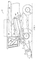
- FIG. 1 shows an agricultural combine 10 comprising a supporting structure 12 having ground engaging wheels 14 extending from the supporting structure.
- the operation of the combine is controlled from operator's cab 15.
- a harvesting platform 16 is used for harvesting a crop and directing it to a feederhouse 18.
- the harvested crop is directed by the feederhouse 18 to a beater 20.
- the beater directs the crop upwardly through an inlet transition section 22 to an axial crop processing unit 24 which serves as a threshing and separating mechanism.
- the crop processing unit 24 threshes and separates the harvested crop material. Grain and chaff fall through grates on the bottom of the unit 24 to the cleaning system 26.
- the cleaning system 26 removes the chaff and directs the clean grain to a clean grain elevator (not shown).
- the clean grain elevator deposits the clean grain in grain tank 28.
- the clean grain in the tank 28 can be unloaded into a grain cart or truck by unloading auger 30.
- Threshed and separated straw is discharged from the axial crop processing unit 24 through outlet 32 to discharge beater 34.
- the discharge beater 34 in turn propels the straw out the rear of the combine.
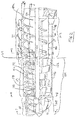
- the axial crop processing unit 24 comprises a rotor housing 36 and a rotor 37 located inside the housing 36.
- the front part of the rotor 37 and the rotor housing 36 define the infeed section 38 of the crop processing unit.
- Longitudinally downstream from the infeed section 38 are threshing section 39 and separating section 40.
- the rotor 37 comprises a drum 100 to which crop processing elements for the infeed section, threshing section, and separating section are affixed.
- the drum 100 comprises a rearward cylindrical portion 102 and a forwardly extending frusto-conical portion 104.
- the rotor 37 shown in FIG. 2 is similar to the rotor explained in more detail in U.S. patent No. 7,070,498 , herein incorporated by reference. However, in contrast to the rotor shown in U.S. patent No. 7,070,498 , the rotor 37 within the threshing section 39 includes a long tapered profile throughout the threshing section 39 without the cylindrical portion within the threshing section as described in US 7 070 498 B . Alternatively, the rotor could be a rotor having the shape such as shown US 5 688 170 B . The invention is useful with and encompasses all of these rotors.
- the rotor 37 in the infeed section 38 is provided with helical infeed elements 42 located on the frusto-conical portion of the drum 100.
- the helical infeed elements 42 engage harvested crop material received from the beater 20 and inlet transition section 22.
- the rotor 37 is provided with a number of threshing elements 122 for threshing the harvested crop material received from the infeed section 38.
- the separating section 40 of the rotor includes outwardly projecting tines 126 similar to the tines disclosed in FIGS. 11 and 12 of US 5 112 279 A , herein incorporated by reference.
- the threshing section 39 of the rotor housing is provided with a concave 146 and the separating section 40 is provided with a grate 148. Grain and chaff released from the crop mat falls through the concave 146 and the grate 148. The concave and grate prevent the passage of crop material larger than grain or chaff from entering the cleaning system 26.
- the rotor is axially arranged in the combine and defines a central rotor axis RA.
- the rotor axis RA is a straight line passing through the infeed, threshing and separating portions of the rotor.
- the infeed section 38 of the rotor housing 36 is provided with a closed cover 162 and a closed bottom 164.
- the cover 162 is provided with helical indexing vanes 165.
- the cover and bottom are bolted to axial rails 166 and 168.
- the forward portion of the closed bottom 164 is provided with an inlet transition section which is similar to one of those disclosed in US 7 070 498 B or US 5 344 367 A , herein incorporated by reference.
- the closed cover 162 of the infeed section 38 defines an infeed axis IA.
- the infeed axis IA is parallel to and substantially collinear with the rotor axis RA defined by the rotor.
- the infeed portion of the rotor is substantially concentrically arranged in the infeed section 38 of the rotor housing as defined by the cover 162.
- the threshing section 39 is provided with a closed threshing cover 172 having helical vanes 174.
- the cover is bolted to axial rails 166 and 168.
- the concave 146 is pivotally mounted to the frame of the combine below rail 168 at 175.
- An adjustment assembly 176 for adjusting concave clearance is mounted to the frame of the combine below rail 166.
- the concave 146 is provided with a closed extension 178.
- the threshing cover 172 defines a threshing axis TA that is parallel to the rotor axis RA.
- the threshing axis is located above the rotor axis RA.
- the threshing axis is slightly offset to the side of the rotor axis in a downstream direction. As such, the cover of the threshing section is eccentrically arranged relative to the threshing portion of the rotor.
- the separating section 40 is provided with a separating cover 180 having helical vanes 182.
- the cover is bolted to axial rails 166 and 168.
- Grate 148 is also bolted to rails 166 and 168.
- Grate 148 is similar to the grate disclosed in US 4 875 891 A .
- the separating cover 180 defines a separating axis SA that is parallel to the rotor axis RA.
- the separating axis is located above the rotor axis RA.
- the separating axis is offset to the side of the rotor axis in a downstream direction.
- the cover of the separating section is eccentrically arranged relative to the separating portion of the rotor.
- a frusto-conical transition section 200 is provided between the threshing section 39 and the separating section 40, overlapping each section.
- the transition section 200 includes a cover 210 having a substantially frusto-conical curvature.
- the cover 210 includes vanes 214a, 214b.
- the vane 214a has a relatively wide width similar to the vanes 174 of the threshing section 39.
- the vane 214a is substantially continuous with the last vane 182a of the separating section 40.
- the vane 214b has a relatively wide width section 214c similar to the width of the vane 174 of the threshing section 39, and a relatively thinner width section 214d similar to the width of the vane 182 of the separating section 40.
- the cover 210 has a taper angle "G" that is substantially equal to a taper angle "H” of the rotor drum 100 within the threshing section 39 for the rotor shown in Figure 2 .
- Some rotors provided a further, reverse taper portion 220 of the rotor drum 100 at an outlet end of the processing unit 24 having an angle of taper "J.”
- a deflecting plate 180a in the separator cover 180 can be arranged over the reverse taper portion 220 to provide for a smooth, energy-efficient flow of crop material.
- the deflecting plate taper angle "K" is preferably substantially equal to the rotor angle "J.”
- the rotor 37a shown in FIG. 2A is substantially the same rotor in US 7 070 498 B .
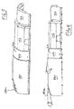
- the rotor 37b shown in FIG. 2B is such as shown US 5 688 170 A .
- the transition section 200 of the housing 36 allows for a smooth flow transition and a gradually increasing radial distance "D" between the top of the housing cover 210 and the rotor axis from the inlet of the transition section 200 to the outlet of the transition section 200.
Landscapes
- Life Sciences & Earth Sciences (AREA)
- Environmental Sciences (AREA)
- Threshing Machine Elements (AREA)
- Harvester Elements (AREA)
Abstract
Description
- The invention relates to rotors and housings for axial rotary agricultural combines.
- Agricultural combines are large machines that harvest, thresh, separate and clean an agricultural crop. The resulting clean grain is stored in a grain tank located on the combine. The clean grain can then be transported from the grain tank to a truck, grain cart or other receiving bin by an unloading auger.
- Rotary combines have one or two large rotors for threshing and separating the harvested crop material. In most rotary combines the rotor or rotors are arranged along the longitudinal axis of the machine. These rotors are provided with an infeed section for receiving harvested crop material, a threshing section for threshing the harvested crop material received from the infeed section and a separating section for freeing grain trapped in the threshed crop material received from the threshing section.
- Rotors have been provided for combines in a variety of configurations to optimize harvesting efficiency for a wide variety of crops and crop conditions.
- Examples are shown in
US 5 445 563 A andUS 5 688 170 A . These two patents both disclose rotary crop processing units having two or more sections. The relationship between the rotor axis and the housing axis varies from one section to the other. The rotor axis becomes increasingly offset from the housing axis in the crop flow direction from the housing inlet to the housing outlet. This is accomplished by abrupt transitions in the housing structure between sections where the housing shape changes. As the housing shape changes, the housing axis steps upward relative to the rotor axis and the gap between the rotor and the top of the housing increases at each step in the housing. -
US 7 070 498 B describes a combine rotor having both infeed and threshing sections on a common frusto-conical portion of the rotor drum. The rotor in the infeed section is provided with helical infeed elements located on the fore-region of the frusto-conical portion of the drum. Immediately downstream from the infeed section, the threshing section is provided with a number of threshing elements. A portion of the threshing elements are attached to the aft-region of the frusto-conical portion of the drum, with the remaining portion being attached to the rearward cylindrical portion. - In such rotary combines, due to the shape and sizing of the housing covers, the rotor housing expands in steps as the material moves rearward. The first step is over the threshing area. The other expansion point is over the separator portion of the rotor. For a rotor design such as disclosed in
US 7 070 498 B , the annular gap defined between the top cover and the rotor tapers to a minimum at the midpoint of the threshing section. The annular gap defined between the rotor and the cover step expands again at the start of the separating section. This abrupt expansion causes excess or wasted power consumption, excess wear and straw damage without increasing threshing capacity. - The present inventors have recognized that a need exists for providing a rotor housing for an axial rotary agricultural combine that provides for efficient energy consumption, an increased wear life, and decreased threshing damage to the grain harvested.
- This object is achieved with the subject matter of claim 1. The dependent claims recite advantageous embodiments.
- The invention provides a threshing and separating mechanism for a combine. The mechanism includes an elongated rotor mounted for rotation about a rotor axis on the combine within a rotor housing. The rotor has a threshing portion and a separating portion. The housing has a threshing section and a separating section corresponding to the threshing portion and the separating portion. The housing surrounds the rotor and is spaced from the rotor to form an annular space between the rotor and the housing for crop material to flow through in an axial crop flow direction from an inlet end of the housing to an outlet end of the housing.
- The housing has a top that is raised above the rotor to define a first distance between the top of the threshing section of the housing and the rotor axis, and a second distance between the top separating section of the housing and the rotor axis.
- The housing includes a transition section between the threshing section and the separating section of the housing. The transition section is arranged over an outlet portion of the threshing portion of the rotor and an inlet portion of the separating portion of the rotor. The top of the housing is raised above the rotor at an inlet end of the transition section to define a third distance between the rotor axis and the top of the transition section. The top of the housing is raised above the rotor at an outlet end of the transition section to define a fourth distance between the rotor axis and the top of the transition section, the third distance substantially equal to the first distance and the fourth distance substantially equal to the second distance.
- This configuration provides a smooth, energy-efficient, wear resistant, and crop protecting transition of crop material flow between the threshing section and the separating section of the rotor housing.
- According to one embodiment, the housing has a top that is raised above the rotor to define a first gap between the top of the threshing section of the housing and the rotor, and a second gap between the top separating section of the housing and the rotor. According to this embodiment the housing includes a transition section between the threshing section and the separating section of the housing. The transition section is arranged over an outlet portion of the threshing portion of the rotor and an inlet portion of the separating portion of the rotor. The top of the housing is raised above the rotor at an inlet end of the transition section to define a third gap between the rotor and the top of the transition section. The top of the housing is raised above the rotor at an outlet end of the transition section to define a fourth gap between the rotor and the top of the transition section, the third gap substantially equal to the first gap and the fourth gap substantially equal to the second gap.
- This configuration also provides a smooth, energy-efficient, wear resistant, and crop protecting transition of crop material flow between the threshing section and the separating section of the rotor housing.
- According to another embodiment, the transition section of the housing, when viewed in a vertical section along the housing axis, is frusto-conical and the gap between the rotor and the top of the housing continuously increases in the crop flow direction within the threshing section and within the separating section.
- Preferably, the rotor comprises a tube, that when viewed in a vertical section along the housing axis, is frusto-conical within the threshing section.
- The invention also provides an axial flow combine for harvesting, threshing and separating crop material that includes a supporting structure, wheels, tracks or the like extending from the supporting structure for transporting the supporting structure around a field, and a threshing and separating mechanism supported on the supporting structure.
- The threshing and separating mechanism includes a rotor housing located inside the supporting structure. The rotor housing is provided with a threshing section in which crop material is threshed and a separating section in which threshed grain is separated from threshed crop material. A rotor is located in the rotor housing having a rotor axis, wherein the rotor is provided with crop engaging assemblies for engaging crop material passing through the rotor housing. The threshing section of the rotor housing is arranged so that the threshing axis has a first eccentricity with respect to the rotor axis and the separating section of the rotor housing is arranged so that the separating axis has a second eccentricity with respect to the rotor axis, the first eccentricityl being less than the second eccentricity. A substantially frusto-conical transition section connects the threshing section of the rotor housing to the separating section of the rotor housing.
- Preferably, the rotor housing is arranged so that the separating axis is located parallel to and above the rotor axis.
- Preferably, the housing separating section includes a separating grate.
- The transition section of the housing lowers power consumption and increases throughput of the rotor. The coned transition top cover is at an angle similar to the rotor taper in the threshing section for increased flow with a gradual expansion to the separating section. This gradual expansion also decreases wear on the rotor and rotor housing and decreases crop damage.
- Numerous other advantages and features of the present invention will be become readily apparent from the following detailed description of the invention and the embodiments thereof, and from the accompanying drawings, in which:
-
Figure 1 is a diagrammatic side view of an agricultural combine the present invention; -
Figure 2 is a diagrammatic side view of a crop processing unit taken from the combine shown inFigure 1 ; -
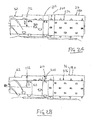
Figure 2A is a diagrammatic side view of a crop processing unit taken from the combine shown inFigure 1 with an alternate rotor; -
Figure 2B is a diagrammatic side view of a crop processing unit taken from the combine shown inFigure 1 with a further alternate rotor; -
Figure 3 is a perspective view of a cover for a crop processing unit ofFigure 2 ; -
Figure 4 is a side view of the cover shown inFigure 3 ; -
Figure 5 is a bottom view of the cover shown inFigure 3 ; -
Figure 6 is a perspective bottom view of the cover shown inFigure 3 ; -
Figure 7 is a sectional view taken generally along line 7-7 ofFigure 2 ; -
Figure 8 is a sectional view taken generally along line 8-8 ofFigure 2 ; and -
Figure 9 is a sectional view taken generally along line 9-9 ofFigure 2 . -
FIG. 1 shows an agricultural combine 10 comprising a supportingstructure 12 havingground engaging wheels 14 extending from the supporting structure. The operation of the combine is controlled from operator'scab 15. A harvesting platform 16 is used for harvesting a crop and directing it to afeederhouse 18. The harvested crop is directed by thefeederhouse 18 to abeater 20. The beater directs the crop upwardly through an inlet transition section 22 to an axialcrop processing unit 24 which serves as a threshing and separating mechanism. - The
crop processing unit 24 threshes and separates the harvested crop material. Grain and chaff fall through grates on the bottom of theunit 24 to the cleaning system 26. The cleaning system 26 removes the chaff and directs the clean grain to a clean grain elevator (not shown). The clean grain elevator deposits the clean grain ingrain tank 28. The clean grain in thetank 28 can be unloaded into a grain cart or truck by unloadingauger 30. Threshed and separated straw is discharged from the axialcrop processing unit 24 through outlet 32 to discharge beater 34. The discharge beater 34 in turn propels the straw out the rear of the combine. - As illustrated in
FIG. 2 , the axialcrop processing unit 24 comprises arotor housing 36 and arotor 37 located inside thehousing 36. The front part of therotor 37 and therotor housing 36 define theinfeed section 38 of the crop processing unit. Longitudinally downstream from theinfeed section 38 are threshingsection 39 and separating section 40. Therotor 37 comprises adrum 100 to which crop processing elements for the infeed section, threshing section, and separating section are affixed. Thedrum 100 comprises a rearward cylindrical portion 102 and a forwardly extending frusto-conical portion 104. - The
rotor 37 shown inFIG. 2 is similar to the rotor explained in more detail inU.S. patent No. 7,070,498 , herein incorporated by reference. However, in contrast to the rotor shown inU.S. patent No. 7,070,498 , therotor 37 within the threshingsection 39 includes a long tapered profile throughout the threshingsection 39 without the cylindrical portion within the threshing section as described inUS 7 070 498 BUS 5 688 170 B . The invention is useful with and encompasses all of these rotors. - The
rotor 37 in theinfeed section 38 is provided withhelical infeed elements 42 located on the frusto-conical portion of thedrum 100. Thehelical infeed elements 42 engage harvested crop material received from thebeater 20 and inlet transition section 22. - In the threshing
section 39 therotor 37 is provided with a number of threshingelements 122 for threshing the harvested crop material received from theinfeed section 38. - The separating section 40 of the rotor includes outwardly projecting
tines 126 similar to the tines disclosed in FIGS. 11 and 12 ofUS 5 112 279 A , herein incorporated by reference. - The threshing
section 39 of the rotor housing is provided with a concave 146 and the separating section 40 is provided with a grate 148. Grain and chaff released from the crop mat falls through the concave 146 and the grate 148. The concave and grate prevent the passage of crop material larger than grain or chaff from entering the cleaning system 26. - The rotor is axially arranged in the combine and defines a central rotor axis RA. The rotor axis RA is a straight line passing through the infeed, threshing and separating portions of the rotor.
- As seen in
FIG. 7 , theinfeed section 38 of therotor housing 36 is provided with aclosed cover 162 and aclosed bottom 164. Thecover 162 is provided withhelical indexing vanes 165. The cover and bottom are bolted toaxial rails closed bottom 164 is provided with an inlet transition section which is similar to one of those disclosed inUS 7 070 498 BUS 5 344 367 A , herein incorporated by reference. - The
closed cover 162 of theinfeed section 38 defines an infeed axis IA. The infeed axis IA is parallel to and substantially collinear with the rotor axis RA defined by the rotor. As such, the infeed portion of the rotor is substantially concentrically arranged in theinfeed section 38 of the rotor housing as defined by thecover 162. - As seen in
FIG. 8 , the threshingsection 39 is provided with aclosed threshing cover 172 havinghelical vanes 174. The cover is bolted toaxial rails rail 168 at 175. Anadjustment assembly 176 for adjusting concave clearance is mounted to the frame of the combine belowrail 166. The concave 146 is provided with a closed extension 178. - The threshing
cover 172 defines a threshing axis TA that is parallel to the rotor axis RA. The threshing axis is located above the rotor axis RA. In addition, the threshing axis is slightly offset to the side of the rotor axis in a downstream direction. As such, the cover of the threshing section is eccentrically arranged relative to the threshing portion of the rotor. - The separating section 40 is provided with a separating
cover 180 havinghelical vanes 182. The cover is bolted toaxial rails rails US 4 875 891 A . - The separating
cover 180 defines a separating axis SA that is parallel to the rotor axis RA. The separating axis is located above the rotor axis RA. In addition, the separating axis is offset to the side of the rotor axis in a downstream direction. As such, the cover of the separating section is eccentrically arranged relative to the separating portion of the rotor. - According to the preferred embodiment of the present invention, a frusto-
conical transition section 200 is provided between the threshingsection 39 and the separating section 40, overlapping each section. - The
transition section 200 includes acover 210 having a substantially frusto-conical curvature. Thecover 210 includes vanes 214a, 214b. The vane 214a has a relatively wide width similar to thevanes 174 of the threshingsection 39. The vane 214a is substantially continuous with the last vane 182a of the separating section 40. The vane 214b has a relativelywide width section 214c similar to the width of thevane 174 of the threshingsection 39, and a relatively thinner width section 214d similar to the width of thevane 182 of the separating section 40. - Preferably, for smooth, energy-efficient flow, the
cover 210 has a taper angle "G" that is substantially equal to a taper angle "H" of therotor drum 100 within the threshingsection 39 for the rotor shown inFigure 2 . - Some rotors provided a further,
reverse taper portion 220 of therotor drum 100 at an outlet end of theprocessing unit 24 having an angle of taper "J." A deflecting plate 180a in theseparator cover 180 can be arranged over thereverse taper portion 220 to provide for a smooth, energy-efficient flow of crop material. Preferably the deflecting plate taper angle "K" is preferably substantially equal to the rotor angle "J." - The rotor 37a shown in
FIG. 2A is substantially the same rotor inUS 7 070 498 BFIG. 2B is such as shownUS 5 688 170 A . As can be seen in these diagrammatic side views ofFIGS. 2 ,2A and 2B , thetransition section 200 of thehousing 36 allows for a smooth flow transition and a gradually increasing radial distance "D" between the top of thehousing cover 210 and the rotor axis from the inlet of thetransition section 200 to the outlet of thetransition section 200. Also, forFIG. 2A and 2B there is a gap "P", taken between the rotor and the top of thehousing cover 210 from the inlet to the outlet of thetransition section 200 that gradually increases within the threshing section and within the separating section.
Claims (12)
- A threshing and separating mechanism for a combine (10) having a supporting structure (12), the mechanism comprising:an elongated rotor (37) mounted in the supporting structure (12) for rotation about a rotor axis (RA), the rotor (37) having a threshing portion and a separating portion; an elongated housing (36) mounted in the supporting structure (12), the housing having a threshing section (39) and a separating section (40), the housing (36) surrounding the rotor (37) and being spaced from the rotor (36) to form an annular space between the rotor (37) and the housing (36) for crop material to flow through in a crop flow direction from an inlet end of the housing (36) to an outlet end of the housing (36), the threshing portion of the rotor (37) corresponding to the threshing section (39) of the housing and the separating portion of the rotor (37) corresponding to the separating section (40) of the housing (36);the housing (36) having a top that is raised above the rotor (37) to define a first distance between the top of the threshing section of the housing (36) and the rotor axis (RA), and a second distance between the top of the separating section of the housing (36) and the rotor axis;characterized in that the housing (36) having a transition section (200) between the threshing section (39) and the separating section (40) of the housing (30), and arranged over an outlet portion of the threshing portion of the rotor (37) and an inlet portion of the separating portion of the rotor (37), the top of the housing (36) being raised above the rotor (37) at an inlet end of the transition section (200) to define a third distance between the top of the transition section (200) and the rotor axis (RA), said top of the housing being raised above the rotor (37) at an outlet end of said transition section (200) to define a fourth distance between the top of the transition section (200) and the rotor axis (RA), the third distance is substantially equal to said first distance and said fourth distance is substantially equal to said second distance.
- The threshing and separating mechanism of claim 1, wherein the housing (36) is generally circular in a radial section.
- The threshing and separating mechanism of claim 2, wherein the rotor (37) is generally cylindrical, the threshing portion of the rotor (37) having a threshing diameter and the separating portion of the rotor (37) having a separating diameter, the threshing and separating diameters being unequal.
- The threshing and separating mechanism of claim 3, wherein the separating diameter is larger than the threshing diameter.
- The threshing and separating mechanism of claim 4, wherein the transition section of the housing (36), when viewed in a vertical section along the housing axis, is frusto-conical and the distance between rotor axis (RA) and the top of the housing continuously increases in the crop flow direction from the threshing section to the separating section.
- The threshing and separating mechanism of claim 5, wherein the housing (36) has in inlet section which is generally cylindrical and located in front of the threshing section (39) in the crop flow direction.
- The threshing and separating mechanism of claim 1, wherein the rotor (37) comprises a tube, that when viewed in a vertical section along the housing axis, is frusto-conical within the threshing section.
- The threshing and separating mechanism of claim 7, wherein the housing (36) has an inlet section which is generally cylindrical and located in front of the threshing section (39) in the crop flow direction.
- An axial flow combine (10) for harvesting, threshing and separating crop material comprising:a supporting structure (12);ground engaging means (14) extending from the supporting structure (12) for transporting the supporting structure (12) around a field; anda threshing and separating mechanism according to one of the preceding claims.
- A combine (10) according to claim 9, wherein the threshing section of the rotor (37) defines a threshing axis and the separating section defines a separating axis and the threshing section (39) of the housing (36) is arranged so that the threshing axis has a first eccentricity with respect to the rotor axis (RA) and the separating section (40) of the housing (36) is arranged so that the separating axis has a second eccentricity with respect to the rotor axis (RA), said first eccentricity less than said second eccentricity, and wherein the transition section (200) is substantially frusto-conical.
- The combine of claim 10, wherein the housing (36) is arranged so that the separating axis is located parallel to and above the rotor axis (RA).
- The combine of one of claims 9 to 11, including a plurality of generally helical vanes (214) mounted on the transition section (200) of the housing (36) and extending into the space between the rotor (37) and the transition section (200) to engage crop material therein and direct it in a rearward spiral.
Applications Claiming Priority (1)
| Application Number | Priority Date | Filing Date | Title |
|---|---|---|---|
| US11/982,418 US8021219B2 (en) | 2007-10-31 | 2007-10-31 | Top cover for axial rotary combine having coned transition |
Publications (2)
| Publication Number | Publication Date |
|---|---|
| EP2055176A1 true EP2055176A1 (en) | 2009-05-06 |
| EP2055176B1 EP2055176B1 (en) | 2010-12-22 |
Family
ID=40316889
Family Applications (1)
| Application Number | Title | Priority Date | Filing Date |
|---|---|---|---|
| EP08162875A Active EP2055176B1 (en) | 2007-10-31 | 2008-08-25 | Top cover for an axial rotary combine having a coned transition |
Country Status (7)
| Country | Link |
|---|---|
| US (1) | US8021219B2 (en) |
| EP (1) | EP2055176B1 (en) |
| AR (1) | AR069118A1 (en) |
| BR (1) | BRPI0804366B1 (en) |
| DE (1) | DE602008004054D1 (en) |
| RU (1) | RU2494602C2 (en) |
| UA (1) | UA99814C2 (en) |
Cited By (5)
| Publication number | Priority date | Publication date | Assignee | Title |
|---|---|---|---|---|
| CN101953257A (en) * | 2009-07-17 | 2011-01-26 | 迪尔公司 | Threshing separation cylinder, threshing separation device and combine harvester |
| CN102656993A (en) * | 2012-04-24 | 2012-09-12 | 广西开元机器制造有限责任公司 | Combing and threshing tooth for miniature semi-feed combine harvester |
| DE102011017618A1 (en) | 2011-04-27 | 2012-10-31 | Deere & Company | Threshing- and separating device for use in self-propelled combine harvester to harvest plants from e.g. grain for separating crops from chaff in agricultural field, has rotor drivable with electromotor with adjustable rotation speed |
| CN103947386A (en) * | 2014-05-09 | 2014-07-30 | 黑河市方圆农机技术开发有限责任公司 | Bottom-feeding vertical type axial flow threshing device |
| DE102013214984A1 (en) | 2013-07-31 | 2015-02-05 | Deere & Company | Arrangement for loss measurement in a combine harvester |
Families Citing this family (5)
| Publication number | Priority date | Publication date | Assignee | Title |
|---|---|---|---|---|
| US8221202B2 (en) * | 2007-11-29 | 2012-07-17 | Deere & Company | Fully tapered rotor nose and threshing section |
| DE102010037416A1 (en) * | 2010-09-09 | 2012-03-15 | Claas Selbstfahrende Erntemaschinen Gmbh | Separator unit for a combine harvester |
| CN105123094B (en) * | 2015-09-22 | 2017-12-12 | 雷沃重工股份有限公司 | Longitudinal axial flow united reaper |
| CN112586197A (en) * | 2020-11-09 | 2021-04-02 | 李春雪 | High-efficient separator of oil sunflower seed |
| EP4388859A1 (en) | 2022-12-19 | 2024-06-26 | CNH Industrial Belgium N.V. | A crop processing assembly for a combine harvester |
Citations (8)
| Publication number | Priority date | Publication date | Assignee | Title |
|---|---|---|---|---|
| US4159023A (en) * | 1977-08-02 | 1979-06-26 | Sperry Rand Corporation | Infeed means for axial flow combine |
| US4505279A (en) * | 1983-08-08 | 1985-03-19 | Sperry Corporation | Staggered spiral rasp bar segments for axial flow combines |
| US4875891A (en) | 1987-03-02 | 1989-10-24 | Deere & Company | Separating grate for a grain harvester |
| US5112279A (en) | 1991-05-10 | 1992-05-12 | Deere & Company | Discharge structure for an axial separator |
| US5344367A (en) | 1993-03-31 | 1994-09-06 | Deere & Company | Infeed plate for an axial agricultural combine |
| US5445563A (en) | 1993-07-01 | 1995-08-29 | Deere & Company | Axial flow combine having a concentric threshing section and an eccentric separating section |
| US5688170A (en) | 1993-07-01 | 1997-11-18 | Deere & Company | Rotary combine having a concentric infeed section and eccentric threshing and separating sections |
| US7070498B2 (en) | 2003-07-29 | 2006-07-04 | Deere & Company | Frusto-conical drum infeed and threshing region for a combine rotor |
Family Cites Families (11)
| Publication number | Priority date | Publication date | Assignee | Title |
|---|---|---|---|---|
| CA931850A (en) * | 1968-04-17 | 1973-08-14 | H. Mcneil Donald | Combine harvester |
| DE2830384C3 (en) * | 1978-07-11 | 1981-10-29 | Adlerwerke Vorm. Heinrich Kleyer Ag, 6000 Frankfurt | Tab rail for typewriters |
| CA1107168A (en) * | 1979-01-12 | 1981-08-18 | White Motor Corporation Of Canada Limited | Rotor for an axial flow combine |
| US4274426A (en) * | 1980-03-31 | 1981-06-23 | Williams Dennis W | Threshing apparatus |
| US4353376A (en) | 1981-03-12 | 1982-10-12 | Schuler Murry W | Combine having separating and cleaning apparatus |
| SU1595386A1 (en) * | 1983-12-27 | 1990-09-30 | Головное Специализированное Конструкторское Бюро По Машинам Для Уборки Зерновых Культур И Самоходным Шасси | Threshing device of axial grain harvester |
| SU1333262A1 (en) * | 1986-03-14 | 1987-08-30 | Московский институт инженеров сельскохозяйственного производства им.В.П.Горячкина | Thrashing and separating device for grain combine harvester |
| US5498206A (en) | 1994-08-08 | 1996-03-12 | Deere & Company | Rethreshing rotor for grain combine |
| US5497605A (en) | 1994-11-15 | 1996-03-12 | Deere & Company | Header and feeder for a grain combine |
| US5803807A (en) * | 1996-11-27 | 1998-09-08 | Caterpillar Inc. | Supporting system for a rotating concave grain threshing mechanism |
| US6468152B2 (en) | 2001-03-02 | 2002-10-22 | Deere & Company | Rotary combine having a frusto-conical rotor housing |
-
2007
- 2007-10-31 US US11/982,418 patent/US8021219B2/en active Active
-
2008
- 2008-08-25 EP EP08162875A patent/EP2055176B1/en active Active
- 2008-08-25 DE DE602008004054T patent/DE602008004054D1/en active Active
- 2008-10-15 UA UAA200812181A patent/UA99814C2/en unknown
- 2008-10-17 BR BRPI0804366-3A patent/BRPI0804366B1/en active IP Right Grant
- 2008-10-30 RU RU2008143124/13A patent/RU2494602C2/en not_active IP Right Cessation
- 2008-10-30 AR ARP080104751A patent/AR069118A1/en active IP Right Grant
Patent Citations (8)
| Publication number | Priority date | Publication date | Assignee | Title |
|---|---|---|---|---|
| US4159023A (en) * | 1977-08-02 | 1979-06-26 | Sperry Rand Corporation | Infeed means for axial flow combine |
| US4505279A (en) * | 1983-08-08 | 1985-03-19 | Sperry Corporation | Staggered spiral rasp bar segments for axial flow combines |
| US4875891A (en) | 1987-03-02 | 1989-10-24 | Deere & Company | Separating grate for a grain harvester |
| US5112279A (en) | 1991-05-10 | 1992-05-12 | Deere & Company | Discharge structure for an axial separator |
| US5344367A (en) | 1993-03-31 | 1994-09-06 | Deere & Company | Infeed plate for an axial agricultural combine |
| US5445563A (en) | 1993-07-01 | 1995-08-29 | Deere & Company | Axial flow combine having a concentric threshing section and an eccentric separating section |
| US5688170A (en) | 1993-07-01 | 1997-11-18 | Deere & Company | Rotary combine having a concentric infeed section and eccentric threshing and separating sections |
| US7070498B2 (en) | 2003-07-29 | 2006-07-04 | Deere & Company | Frusto-conical drum infeed and threshing region for a combine rotor |
Cited By (8)
| Publication number | Priority date | Publication date | Assignee | Title |
|---|---|---|---|---|
| CN101953257A (en) * | 2009-07-17 | 2011-01-26 | 迪尔公司 | Threshing separation cylinder, threshing separation device and combine harvester |
| DE102011017618A1 (en) | 2011-04-27 | 2012-10-31 | Deere & Company | Threshing- and separating device for use in self-propelled combine harvester to harvest plants from e.g. grain for separating crops from chaff in agricultural field, has rotor drivable with electromotor with adjustable rotation speed |
| DE102011017618B4 (en) | 2011-04-27 | 2024-11-14 | Deere & Company | Axial threshing and separating device for a combine harvester |
| CN102656993A (en) * | 2012-04-24 | 2012-09-12 | 广西开元机器制造有限责任公司 | Combing and threshing tooth for miniature semi-feed combine harvester |
| CN102656993B (en) * | 2012-04-24 | 2014-04-09 | 广西开元机器制造有限责任公司 | Combing and threshing tooth for miniature semi-feed combine harvester |
| DE102013214984A1 (en) | 2013-07-31 | 2015-02-05 | Deere & Company | Arrangement for loss measurement in a combine harvester |
| EP2845461A1 (en) | 2013-07-31 | 2015-03-11 | Deere & Company | Assembly for measuring loss in a combine harvester |
| CN103947386A (en) * | 2014-05-09 | 2014-07-30 | 黑河市方圆农机技术开发有限责任公司 | Bottom-feeding vertical type axial flow threshing device |
Also Published As
| Publication number | Publication date |
|---|---|
| DE602008004054D1 (en) | 2011-02-03 |
| US20090111546A1 (en) | 2009-04-30 |
| EP2055176B1 (en) | 2010-12-22 |
| US8021219B2 (en) | 2011-09-20 |
| BRPI0804366B1 (en) | 2019-02-26 |
| RU2008143124A (en) | 2010-05-10 |
| BRPI0804366A2 (en) | 2010-01-19 |
| RU2494602C2 (en) | 2013-10-10 |
| AR069118A1 (en) | 2009-12-30 |
| UA99814C2 (en) | 2012-10-10 |
Similar Documents
| Publication | Publication Date | Title |
|---|---|---|
| EP2055176B1 (en) | Top cover for an axial rotary combine having a coned transition | |
| US8221202B2 (en) | Fully tapered rotor nose and threshing section | |
| EP2064939B1 (en) | Adjustable Rear Rotor Discharge Flights | |
| US7462101B2 (en) | Frusto-conical drum infeed and threshing region for a combine rotor | |
| EP2055177B1 (en) | Adjustable vane system for an axial flow rotor housing of an agricultural combine | |
| EP0847234B1 (en) | Rotary agricultural combine | |
| EP1964464B1 (en) | Guide vane adjustment for combine harvesters | |
| US5445563A (en) | Axial flow combine having a concentric threshing section and an eccentric separating section | |
| CA2354497C (en) | Rotary combine having a frusto-conical rotor housing | |
| US6083102A (en) | Variable sweep helical infeed element | |
| EP2064938B1 (en) | Rear rotor cone | |
| US6257977B1 (en) | Rotary combine having a rotor axis divergent from a rotor housing axis | |
| US7059960B2 (en) | Composite threshing element for a combine rotor | |
| CA2425847C (en) | Axial separator with guide vane | |
| US5364306A (en) | Notched helical vanes in the feeding section of an axial agricultural combine | |
| RU2512320C2 (en) | Threshing devices for harvester (variants), harvester (variants) and method of movement of agricultural crop through threshing device (variants) | |
| RU2493687C2 (en) | Conical nose part of drum and threshing section |
Legal Events
| Date | Code | Title | Description |
|---|---|---|---|
| PUAI | Public reference made under article 153(3) epc to a published international application that has entered the european phase |
Free format text: ORIGINAL CODE: 0009012 |
|
| AK | Designated contracting states |
Kind code of ref document: A1 Designated state(s): AT BE BG CH CY CZ DE DK EE ES FI FR GB GR HR HU IE IS IT LI LT LU LV MC MT NL NO PL PT RO SE SI SK TR |
|
| AX | Request for extension of the european patent |
Extension state: AL BA MK RS |
|
| 17P | Request for examination filed |
Effective date: 20091106 |
|
| 17Q | First examination report despatched |
Effective date: 20091201 |
|
| AKX | Designation fees paid |
Designated state(s): BE DE DK IT PL SE |
|
| GRAP | Despatch of communication of intention to grant a patent |
Free format text: ORIGINAL CODE: EPIDOSNIGR1 |
|
| GRAS | Grant fee paid |
Free format text: ORIGINAL CODE: EPIDOSNIGR3 |
|
| GRAA | (expected) grant |
Free format text: ORIGINAL CODE: 0009210 |
|
| AK | Designated contracting states |
Kind code of ref document: B1 Designated state(s): BE DE DK IT PL SE |
|
| REF | Corresponds to: |
Ref document number: 602008004054 Country of ref document: DE Date of ref document: 20110203 Kind code of ref document: P |
|
| REG | Reference to a national code |
Ref country code: DE Ref legal event code: R096 Ref document number: 602008004054 Country of ref document: DE Effective date: 20110203 |
|
| PG25 | Lapsed in a contracting state [announced via postgrant information from national office to epo] |
Ref country code: SE Free format text: LAPSE BECAUSE OF FAILURE TO SUBMIT A TRANSLATION OF THE DESCRIPTION OR TO PAY THE FEE WITHIN THE PRESCRIBED TIME-LIMIT Effective date: 20101222 |
|
| PG25 | Lapsed in a contracting state [announced via postgrant information from national office to epo] |
Ref country code: PL Free format text: LAPSE BECAUSE OF FAILURE TO SUBMIT A TRANSLATION OF THE DESCRIPTION OR TO PAY THE FEE WITHIN THE PRESCRIBED TIME-LIMIT Effective date: 20101222 |
|
| PLBE | No opposition filed within time limit |
Free format text: ORIGINAL CODE: 0009261 |
|
| STAA | Information on the status of an ep patent application or granted ep patent |
Free format text: STATUS: NO OPPOSITION FILED WITHIN TIME LIMIT |
|
| PG25 | Lapsed in a contracting state [announced via postgrant information from national office to epo] |
Ref country code: DK Free format text: LAPSE BECAUSE OF FAILURE TO SUBMIT A TRANSLATION OF THE DESCRIPTION OR TO PAY THE FEE WITHIN THE PRESCRIBED TIME-LIMIT Effective date: 20101222 |
|
| 26N | No opposition filed |
Effective date: 20110923 |
|
| REG | Reference to a national code |
Ref country code: DE Ref legal event code: R097 Ref document number: 602008004054 Country of ref document: DE Effective date: 20110923 |
|
| PGFP | Annual fee paid to national office [announced via postgrant information from national office to epo] |
Ref country code: IT Payment date: 20130822 Year of fee payment: 6 |
|
| PG25 | Lapsed in a contracting state [announced via postgrant information from national office to epo] |
Ref country code: IT Free format text: LAPSE BECAUSE OF NON-PAYMENT OF DUE FEES Effective date: 20140825 |
|
| PGFP | Annual fee paid to national office [announced via postgrant information from national office to epo] |
Ref country code: DE Payment date: 20240719 Year of fee payment: 17 |
|
| PGFP | Annual fee paid to national office [announced via postgrant information from national office to epo] |
Ref country code: BE Payment date: 20240827 Year of fee payment: 17 |