EP2054936B1 - Solar charged mobile working stations - Google Patents
Solar charged mobile working stations Download PDFInfo
- Publication number
- EP2054936B1 EP2054936B1 EP07814264.3A EP07814264A EP2054936B1 EP 2054936 B1 EP2054936 B1 EP 2054936B1 EP 07814264 A EP07814264 A EP 07814264A EP 2054936 B1 EP2054936 B1 EP 2054936B1
- Authority
- EP
- European Patent Office
- Prior art keywords
- computer
- recited
- power
- cassette drawer
- cassette
- Prior art date
- Legal status (The legal status is an assumption and is not a legal conclusion. Google has not performed a legal analysis and makes no representation as to the accuracy of the status listed.)
- Active
Links
Images






Classifications
-
- A—HUMAN NECESSITIES
- A61—MEDICAL OR VETERINARY SCIENCE; HYGIENE
- A61B—DIAGNOSIS; SURGERY; IDENTIFICATION
- A61B5/00—Measuring for diagnostic purposes; Identification of persons
- A61B5/0002—Remote monitoring of patients using telemetry, e.g. transmission of vital signals via a communication network
-
- A—HUMAN NECESSITIES
- A61—MEDICAL OR VETERINARY SCIENCE; HYGIENE
- A61G—TRANSPORT, PERSONAL CONVEYANCES OR ACCOMMODATION SPECIALLY ADAPTED FOR PATIENTS OR DISABLED PERSONS; OPERATING TABLES OR CHAIRS; CHAIRS FOR DENTISTRY; FUNERAL DEVICES
- A61G12/00—Accommodation for nursing, e.g. in hospitals, not covered by groups A61G1/00 - A61G11/00, e.g. trolleys for transport of medicaments or food; Prescription lists
- A61G12/001—Trolleys for transport of medicaments, food, linen, nursing supplies
-
- G—PHYSICS
- G06—COMPUTING OR CALCULATING; COUNTING
- G06F—ELECTRIC DIGITAL DATA PROCESSING
- G06F1/00—Details not covered by groups G06F3/00 - G06F13/00 and G06F21/00
- G06F1/26—Power supply means, e.g. regulation thereof
- G06F1/263—Arrangements for using multiple switchable power supplies, e.g. battery and AC
-
- G—PHYSICS
- G16—INFORMATION AND COMMUNICATION TECHNOLOGY [ICT] SPECIALLY ADAPTED FOR SPECIFIC APPLICATION FIELDS
- G16H—HEALTHCARE INFORMATICS, i.e. INFORMATION AND COMMUNICATION TECHNOLOGY [ICT] SPECIALLY ADAPTED FOR THE HANDLING OR PROCESSING OF MEDICAL OR HEALTHCARE DATA
- G16H20/00—ICT specially adapted for therapies or health-improving plans, e.g. for handling prescriptions, for steering therapy or for monitoring patient compliance
- G16H20/10—ICT specially adapted for therapies or health-improving plans, e.g. for handling prescriptions, for steering therapy or for monitoring patient compliance relating to drugs or medications, e.g. for ensuring correct administration to patients
- G16H20/13—ICT specially adapted for therapies or health-improving plans, e.g. for handling prescriptions, for steering therapy or for monitoring patient compliance relating to drugs or medications, e.g. for ensuring correct administration to patients delivered from dispensers
-
- G—PHYSICS
- G16—INFORMATION AND COMMUNICATION TECHNOLOGY [ICT] SPECIALLY ADAPTED FOR SPECIFIC APPLICATION FIELDS
- G16H—HEALTHCARE INFORMATICS, i.e. INFORMATION AND COMMUNICATION TECHNOLOGY [ICT] SPECIALLY ADAPTED FOR THE HANDLING OR PROCESSING OF MEDICAL OR HEALTHCARE DATA
- G16H40/00—ICT specially adapted for the management or administration of healthcare resources or facilities; ICT specially adapted for the management or operation of medical equipment or devices
- G16H40/60—ICT specially adapted for the management or administration of healthcare resources or facilities; ICT specially adapted for the management or operation of medical equipment or devices for the operation of medical equipment or devices
- G16H40/67—ICT specially adapted for the management or administration of healthcare resources or facilities; ICT specially adapted for the management or operation of medical equipment or devices for the operation of medical equipment or devices for remote operation
-
- H—ELECTRICITY
- H02—GENERATION; CONVERSION OR DISTRIBUTION OF ELECTRIC POWER
- H02S—GENERATION OF ELECTRIC POWER BY CONVERSION OF INFRARED RADIATION, VISIBLE LIGHT OR ULTRAVIOLET LIGHT, e.g. USING PHOTOVOLTAIC [PV] MODULES
- H02S99/00—Subject matter not provided for in other groups of this subclass
-
- A—HUMAN NECESSITIES
- A61—MEDICAL OR VETERINARY SCIENCE; HYGIENE
- A61B—DIAGNOSIS; SURGERY; IDENTIFICATION
- A61B2560/00—Constructional details of operational features of apparatus; Accessories for medical measuring apparatus
- A61B2560/02—Operational features
- A61B2560/0204—Operational features of power management
- A61B2560/0214—Operational features of power management of power generation or supply
-
- A—HUMAN NECESSITIES
- A61—MEDICAL OR VETERINARY SCIENCE; HYGIENE
- A61B—DIAGNOSIS; SURGERY; IDENTIFICATION
- A61B2560/00—Constructional details of operational features of apparatus; Accessories for medical measuring apparatus
- A61B2560/04—Constructional details of apparatus
- A61B2560/0437—Trolley or cart-type apparatus
-
- A—HUMAN NECESSITIES
- A61—MEDICAL OR VETERINARY SCIENCE; HYGIENE
- A61B—DIAGNOSIS; SURGERY; IDENTIFICATION
- A61B2560/00—Constructional details of operational features of apparatus; Accessories for medical measuring apparatus
- A61B2560/04—Constructional details of apparatus
- A61B2560/0443—Modular apparatus
-
- A—HUMAN NECESSITIES
- A61—MEDICAL OR VETERINARY SCIENCE; HYGIENE
- A61G—TRANSPORT, PERSONAL CONVEYANCES OR ACCOMMODATION SPECIALLY ADAPTED FOR PATIENTS OR DISABLED PERSONS; OPERATING TABLES OR CHAIRS; CHAIRS FOR DENTISTRY; FUNERAL DEVICES
- A61G2203/00—General characteristics of devices
- A61G2203/30—General characteristics of devices characterised by sensor means
- A61G2203/44—General characteristics of devices characterised by sensor means for weight
-
- G—PHYSICS
- G16—INFORMATION AND COMMUNICATION TECHNOLOGY [ICT] SPECIALLY ADAPTED FOR SPECIFIC APPLICATION FIELDS
- G16H—HEALTHCARE INFORMATICS, i.e. INFORMATION AND COMMUNICATION TECHNOLOGY [ICT] SPECIALLY ADAPTED FOR THE HANDLING OR PROCESSING OF MEDICAL OR HEALTHCARE DATA
- G16H40/00—ICT specially adapted for the management or administration of healthcare resources or facilities; ICT specially adapted for the management or operation of medical equipment or devices
- G16H40/40—ICT specially adapted for the management or administration of healthcare resources or facilities; ICT specially adapted for the management or operation of medical equipment or devices for the management of medical equipment or devices, e.g. scheduling maintenance or upgrades
-
- Y—GENERAL TAGGING OF NEW TECHNOLOGICAL DEVELOPMENTS; GENERAL TAGGING OF CROSS-SECTIONAL TECHNOLOGIES SPANNING OVER SEVERAL SECTIONS OF THE IPC; TECHNICAL SUBJECTS COVERED BY FORMER USPC CROSS-REFERENCE ART COLLECTIONS [XRACs] AND DIGESTS
- Y02—TECHNOLOGIES OR APPLICATIONS FOR MITIGATION OR ADAPTATION AGAINST CLIMATE CHANGE
- Y02E—REDUCTION OF GREENHOUSE GAS [GHG] EMISSIONS, RELATED TO ENERGY GENERATION, TRANSMISSION OR DISTRIBUTION
- Y02E10/00—Energy generation through renewable energy sources
- Y02E10/50—Photovoltaic [PV] energy
Definitions
- the present invention relates to a system comprising a medical workstation including a cart having a computer a battery and a solar charging system.
- wireless computers therefore, has had a tremendous impact on the effectiveness and efficiency of medicine. The more mobile a healthcare professional or employee can be the better chance that a patient can receive prompt and accurate care. Accordingly, there exist wireless work stations having computers that provide such information as medication charts and patient records, and that have e-mail capabilities so that the information can be shared. These work stations can further include features that enable the proper administration of medication.
- a mobile clinical work station exhibiting a vertically mounted docking station for a device, such as a computer terminal.
- the mobile work station also carries a power unit including an extended-life battery and a battery charger that connects to an AC power supply to charge the battery pack of the computer terminal.
- WO 2006/020862 A2 discloses a mobile medical workstation having at least one medical diagnostic instrument disposed thereupon.
- a power supply such as a rechargeable battery, is attached to its lower base.
- a battery pack that comprises a solar panel, a battery and a charge/discharge circuit.
- the solar panel converts light energy into electric energy.
- the battery is charged with the electric energy from the solar panel.
- US 5 260 885 A discloses a solar power operated computer comprising an upper casing and a base pivoted together.
- the upper casing and the base each have a solar cell assembly hinged thereto, respectively, to collect the radiant energy of sunlight and convert it into electric power for charging respective storage batteries.
- the object of the present invention is to increase the autonomy of a mobile medical work station as expressed in time between charges and allowing safety options at the same time.
- the present invention is a medical work station having a solar charging system.
- the medical work station includes a cart that carries a computer for providing access to and keeping track of medical information.
- the solar charging system is operatively connected to the computer to provide a solar power input. This solar input provides a constant replenishing of power to the computer as long as there is a source of UV light, such as through artificial and natural light.
- the computer includes wireless network access and a monitor.
- the monitor includes an LCD screen that draws less power than standard LCD screens currently available.
- the LCD screen draws less than about 2 Amps of power.
- An important feature of the present invention is the use of a solar charging system in combination with a medical work station.
- the use of a solar charging system provides enhanced mobility to the work station, which no longer needs to be plugged into a power source. Additionally, the solar charging system extends the life of the work station as its power is constantly replenished by solar input.
- Another important feature to the present invention includes the use of medical work station having a computer with an LCD screen that draws a certain amount of power so as to provide an overall power reduction to the computer.
- the LCD screen draws less than about 2 Amps of power, so that the computer requires less power input to operate.
- Yet another feature of the present invention includes the use of a medical work station having a computer with an LCD screen and a solar charging system that work in combination to enhance the efficiency and extend the life of the medical work station.
- the computer's solar charging system functions all the more efficiently, as it will require less overall solar input to charge the computer
- Another feature of the present invention is based on the recognition that the environment of use is a medical facility where there is ample lighting particularly, when a cart is in use.
- the recognition of this fact of that environment in combination with the use of a solar panel to charge the cart's battery and that can take advantage of the bright lights in that environment allows the cart to be operated without having to recharge the batteries by other means.
- the present invention is a medical work station having a solar charging system.
- the medical work station includes a cart that carries a computer for providing access to and keeping track of medical information.
- the cart as generally indicated in FIG. 1 by reference number 10, includes a variety of features and embodiments. Accordingly, the cart shown in FIG. 1 is merely exemplary and provided to place the present invention into context.
- cart 10 includes a computer/monitor 12, preferably with both a computer and a monitor in one unit with the computer behind the monitor and in the same housing.
- Computer/monitor 12 is equipped with a wireless network connection so that the user of that cart 10 can communicate with a central administrator. Computer/monitor 12 also communicates with administrator without the active assistance of the user.
- Cart 10 also has a work surface 16 with a slide out keyboard 18. Additionally, surface 16 is mounted on top of a mast 24 carried in turn by a rolling base 26.
- the solar charging system of the present invention is operatively connected to the computer/monitor 12 to provide a solar power input.
- This solar input provides a constant replenishing of power to the computer as long as there is a source of UV light, such as through inside lighting or through sunlight.
- the solar charging system includes a plurality of solar panels 30 that are connected to the computer/monitor 12.
- This solar input provides a constant replenishing of power to the computer as long as there is a source of UV light, such as through inside lighting or through sunlight.
- the solar panels 30 are located near the top of computer/monitor 12 and facing away from the user of the computer/monitor 12.
- the solar panels 30 are rotatably connected to the computer/monitor 12 so that they can be ideally positioned for receiving a source of UV light. Additionally, the solar panels 30 can be releasably connected to the computer/monitor 12 so that they can be both rotated and moved to optimum locations.
- This configuration can be altered based on the conditions of a medical center and the length of the duty cycle. For example, a cart used in an emergency room where lighting is brighter around the clock as opposed to, say, a maternity ward, there may be sufficient lighting for a longer duty cycle and a smaller solar panel. A long term care facility may have even lower levels of lighting and shorter duty cycles. A reasonable amount of experimentation by those skilled at matching solar panel design with environment and duty cycle is required to optimize the panel design for the particular environment.
- the solar charging system of the present invention generates about 1 Amp of power indoors without input from natural light, and about 2 to about 3 Amps of power with the input of natural light.
- the computer/monitor 12 of the workstation should not need recharging if it is operated at less than about 50% duty time.
- an important feature of the present invention is the use of a solar charging system in combination with a medical work station.
- the use of a solar charging system provides enhanced mobility to the work station, which no longer needs to be plugged into a power source. Additionally, the solar charging system extends the life of the work station as its power is constantly replenished by solar input.
- Computer/monitor 12 of the present invention further includes an LCD screen 40 that draws less power than prior art monitors by such means as, for example, keeping the monitor at a modest size, reducing brightness but compensating by increasing contrast.
- Another important feature to the present invention includes the use of medical work station having a computer with an LCD screen 40 that draws a certain amount of power so as to provide an overall power reduction to the computer.
- the LCD screen 40 draws less than about 2 Amps of power, so that the computer requires less power input to operate.
- the LCD screen 40 and solar charging system works in combination to enhance the efficiency and extend the life of the medical work station. With less overall power required to operate the computer, the computer's solar charging system functions all the more efficiently, as it will require less overall solar input to charge the computer.
- the present invention can be employed with any number of types of medical.
- An example of a medical cart that can be used in combination with the solar power system is now described.
- FIG. 6 An exemplary cart is shown generally in Fig. 6 by reference number 10.
- the cart includes a computer/monitor 12, preferably with both a computer and a monitor in one unit with the computer behind the monitor and in the same housing 14.
- Cart 10 also has a work surface 16 with a slide out keyboard 18. There is no security keypad; the keyboard's keypad serves for entry of codes to permit access.
- Work surface 16 is mounted on top of a mast 24 carried in turn by a rolling base 26.
- Work surface 16 can optionally include holders for storing items, such as antibacterial lotions and drinks, which the user may need when making rounds with the cart 10.
- FIG. 7 there is illustrated a rear view of the present cart 10 showing computer/monitor 12, work surface 16, mast 24, and a power system 28, which is carried by rolling base 26.
- Work surface 16 can further include hidden USB port 80 for use if additional electronic devices, such as scanners, need to be employed.
- Computer/monitor 12 is attached to mast 24 or underneath the work surface through a mount 35 so that the entire top area of the work surface 16 is available to the user.
- Computer/monitor 12 is mounted using a tiltable bracket 34 so that the angle of viewing computer/monitor 12 can be adjusted to suit the particular user.
- a clear hard covering is applied over the monitor portion of computer/monitor 12 in order to make computer/monitor less susceptible to scratches and impact.
- the covering is about a 1/8th inch thick and made of acrylic polymeric plastic or other suitable plastic polymer.
- Mast 24 is vertically adjustable so that the user can work seated or standing and users of different heights can work comfortably.
- mast 24 is electronically adjustable by pressing a button 29 rather than by turning a hand crank or other mechanical elevating mechanism.
- the mast 24 is telescoped, with an outer mast member 25 dimensioned to receive an inner mast member 23.
- the raising and lowering of the mast 24 can be controlled by an electrical switch 29 that is connected to the power system 28 and mechanical means (not shown), such as a screw/nut drive system that utilizes a number of small balls (ball screw).
- a user would press the button 29 in one direction, such as forward, to activate the electrical switch 29 to lower the mast 24, and in another direction, such as backward, to activate the electrical switch 29 to raise the mast 24.
- the electrical switch 29 provides input to the power system 28, which controls the raising and lowering of the mast 24 through an actuator connected to the mechanical means.
- the power system can also include a weight sensor connected to the actuator that can be used to override the raising and lowering of mast 24 based on the weight of the work surface 16 and computer/monitor 12. For example, if the combined weight of the work surface 16 and computer/monitor 12 exceeds a preset, desired weight, the actuator will be tripped, and the mast 24 will no longer be moveable through the use of the button 29.
- power system 28 is illustrated in further detail in Figs. 8-9 . If solar input is insufficient to power the medical cart, the power system 28 can provide an alternative source of power as needed to ensure the constant operation of the medical cart.
- work surface 16 further includes a power cord 31 plug rest 33 (shown in Fig. 7 ) for conveniently storing the power cord 31 when the cart 10 is being moved or is not in the vicinity of a power source.
- Battery 27 can be fixed to battery bracket 50 with a variety of mechanical fasteners.
- battery 27 is fixed to battery bracket by two screws 52. By removing screws 52, battery 27 and its associated electronics can be removed from bracket 50 to expose the wiring connections. Once the wiring connections are disconnected, battery 27 can be lifted free using its handle 56. Battery 24 is still in a cover 58 and may remain in cover 58 during recharging.
- battery 27 can be charged in combination with the cart 10 or independently of the cart 10, through a power cord 31.
- work surface 16 further includes a power cord 31 plug rest 33 for conveniently storing the power cord 31 when the cart 10 is being moved or is not in the vicinity of a power source.
- power system 28 can be equipped with an LED indicator to show when the batter 27 is charging and/or fully charged.
- Battery 27 is designed to last through at least one shift of eight hours before requiring recharging, preferably about 10 hours.
- each battery is connected to the balance of cart 10 using a "Y" electrical connector 61 that permits a second, fully charged battery 27 to be connected (for "hot swapping") to the unused part of the Y connector, and then the first battery 28 can be removed from the battery bracket and disconnected from the Y connector without loss of power, or data, to computer/monitor 12, and the second battery can then be installed into the battery bracket.
- the connections that hold battery 28 in its bracket are designed for quick release so battery change out takes but a few minutes at most.
- cart 10 includes a cassette drawer system 41. As illustrated, at least one cassette drawer system 41 is carried below work surface 16. An exploded, detailed view of the cassette drawer system 41 is shown in Fig. 11 .
- Cassette drawer system 41 is preferably modularized, and includes a cassette drawer manager 70, which houses a cassette drawer controller and interface 72 for monitoring the status and activities of cassette drawers and receiving input for computer/monitor 12.
- the cassette drawer system 41 is generally connected to work surface 16 and wired to computer/monitor 12. More particularly, the top of cassette drawer manager 70 is bolted to work surface 16. Accordingly, cassette drawer manager 70 includes bolt fasteners 74 along its top surface.
- cassette drawer manager 70 includes a first key override lock 71 and a second key override lock 73.
- a first key from authorized users will override the cassette drawer manager controller 72 to open the drawers containing certain medication. If narcotic medication needs to be accessed, a user must insert both a first key and a second key to open the narcotics-containing drawers.
- Beneath cassette drawer manager 70 at least one cassette drawer 76 is latched. Depending on the dimensions of the cassette drawer manager 70 and the cassette drawers, up to four drawers 76 can be added. An added drawer 76 cannot be released without opening the drawer. As soon as a drawer 76 is added, it is sensed by controller of computer/monitor 12 and cannot be opened except by a user with an authorizing pass code.
- the latching mechanism between the cassette drawer manager 70 and a cassette drawer 76 will be the same as between a first cassette drawer and a second cassette drawer.
- This latching mechanism is shown in the expanded detailed drawings in Fig. 11 .
- As between the cassette drawer manger 70 and a first cassette drawer on the underside of cassette drawer manager 70 are a plurality of dovetail-shaped cutout portions 80 that are dimensioned to receive dovetail-shaped projections 84.
- dovetail-shaped cutout portions 80 that are dimensioned to receive dovetail-shaped projections 84 on every lower cassette drawer 78. In operation, dovetail projections 84 simply slide into dovetail cutouts 80.
- cassette drawer 76 is seated fully into cassette drawer manager 70, spring tabs 90 having pins 91, which have been cut out from the bottom surface of cassette drawer manager 70, are cammed upward as drawer 76 is slid into place, and snap downward into corresponding recesses 92 in the top surface of drawer 76. Pins 91 on spring tabs 90 will hold drawer 76 in place until drawer 76 is opened by an authorized person who can then pull tabs 90 down to release drawer 76 from manager 70.
- the cassette drawer manager 70 and the cassette drawers are also electronically connected.
- cassette drawer manager 70 and cassette drawer 76 are generally U-shaped to facilitate engagement with the mast 24.
- Each cassette drawer 76 typically has at least two compartments 94 that are independently lockable through electronic locks 100 and that have corresponding sensors 110. Sensors 110 determine if a drawer is open or closed, including of course when a drawer is left open or not fully closed. A drawer that is opened without authorization causes an alarm to sound and initiates an email to the system administrator.
- All locks 100 are software controlled rather than by using keys.
- a lock 100 could include a solenoid actuator connected to a lever and controlled by software. Keys can be lost or stolen or fall into the wrong hands. Furthermore, it is easier to change access pass codes using software than to re-key locks.
- Computer/monitor 12 can be programmed to lock every drawer unless unlocked by a person with the correct level of authorization who enters the correct pass code via keyboard 18. Access to a compartment 94 containing narcotics requires two pass codes; otherwise one pass code unlocks a compartment 94. Each user has his or her own pass code or codes so the user who accesses each drawer is known by the pass code used, as well as the time and date of the access by that user.
- Cart 10 is optionally provided with a plug in scanner for reading medication containers and automatically and accurately loading drawers and the computer database with the correct information about the medications being loaded into each drawer.
- the system administrator can have a real time inventory of medications in all carts in its system, knowing exactly what type and how much medication is in each drawer of each cart
- Cassette drawer system 41 also has an optional utility cassette 78, which can be used to store such items as rubber gloves, paper cups, tissues, and so forth. Because a utility cassette 78 need not be secured, cassette drawer manager 70 automatically deactivates sensors 110 and locks 100 of utility cassette drawers 78 that become part of the cassette drawer system 30.
- FIG. 12 A block diagram of the operating system for the cart 10 is shown in Fig. 12 .
- computer/monitor 12 includes a computer controller and interface logic 200 that receives computer controller input and generates computer controller output.
- computer controller 200 process user input, such as the identity of user, the biometric information of user, pass codes entered by user.
- computer controller provides output to cassette drawer system 41 relating to the designation of cassette drawers included in the cassette drawer system 41.
- computer/monitor 12 can, in real time, inventory medication as it is loaded and as it used, as well as which user is dispensing the medication.
- computer/monitor 12 is equipped with a wireless network connection, preferably through SMTP (simple mail transfer protocol) so that the user of that cart 10 can communicate with a central administrator 400.
- Computer/monitor 12 also communicates with administrator 400 without the active assistance of the user. Accordingly, the status and whereabouts of the cart 10 can be constantly and effectively monitored through wireless communication.
- SMTP simple mail transfer protocol
- the cassette drawer system 41 also includes cassette drawer controller and interface logic 500.
- This cassette drawer controller receives input from the computer controller about the cassette drawers and their designations. Cassette drawer controller, therefore, can lock and unlock drawers based on this input. Furthermore, the cassette drawer controller logs what the drawers do, including when they are opened and by whom. Accordingly, the cassette drawer system 41 has the ability to monitor itself.
- the power system 28 also includes controller and interface logic 600, which monitors the condition of battery 27, and controls the raising and lowering of the mast 24. For example, the condition of the battery 27 when low or when the unit is turning off due to low battery power, power system controller communicates these conditions to computer controller, which in turn reports by email to the administrator. Computer/monitor 12 will also automatically report by email an attempt to break into cart 10, a log of the charging system, a log of the times and the identities of users who have accessed each cassette drawer. Other information can also be reported
- Fig. 13 includes of flow chart.
- a decision is made by medication cart 10 whether the battery 27 is suitable. If the battery 27 is not in a good condition and if communication is required at 701 as to the status of the battery 27, an electronic communication is sent to central administrator at 702. If maintenance is needed, the battery 27 will be charged or replaced at 703. If the battery 27 is in good condition and communication is required at 704, an electronic communication is sent to central administrator at 705.
Landscapes
- Engineering & Computer Science (AREA)
- Health & Medical Sciences (AREA)
- Public Health (AREA)
- General Health & Medical Sciences (AREA)
- Biomedical Technology (AREA)
- Life Sciences & Earth Sciences (AREA)
- Medical Informatics (AREA)
- Veterinary Medicine (AREA)
- Animal Behavior & Ethology (AREA)
- Epidemiology (AREA)
- Primary Health Care (AREA)
- Theoretical Computer Science (AREA)
- Physics & Mathematics (AREA)
- Pathology (AREA)
- General Business, Economics & Management (AREA)
- Computer Networks & Wireless Communication (AREA)
- Heart & Thoracic Surgery (AREA)
- Molecular Biology (AREA)
- Surgery (AREA)
- Medicinal Chemistry (AREA)
- Bioinformatics & Cheminformatics (AREA)
- Business, Economics & Management (AREA)
- Biophysics (AREA)
- Nursing (AREA)
- Power Engineering (AREA)
- General Engineering & Computer Science (AREA)
- General Physics & Mathematics (AREA)
- Chemical & Material Sciences (AREA)
- Accommodation For Nursing Or Treatment Tables (AREA)
- Charge And Discharge Circuits For Batteries Or The Like (AREA)
Description
- The present invention relates to a system comprising a medical workstation including a cart having a computer a battery and a solar charging system.
- As with many other industries, the health care industry strives to provide quick and convenient access to as much useful information as possible to those in need of it. Timely and consistent access to accurate information is especially significant, however, when considering that the health and lives of others are at stake.
- The use of wireless computers, therefore, has had a tremendous impact on the effectiveness and efficiency of medicine. The more mobile a healthcare professional or employee can be the better chance that a patient can receive prompt and accurate care. Accordingly, there exist wireless work stations having computers that provide such information as medication charts and patient records, and that have e-mail capabilities so that the information can be shared. These work stations can further include features that enable the proper administration of medication.
- Although these types of work stations are advantageous in their convenience and capabilities, they can prove to be expensive. Thus, extending the life of the work stations is desirable. Furthermore, the work stations require a significant amount of power that frequently needs recharging.
- Accordingly, there exists a need for a durable work station that can be operated without constant or frequent replenishing of power.
- From
US 6 493 220 B1 a mobile clinical work station is known, exhibiting a vertically mounted docking station for a device, such as a computer terminal. The mobile work station also carries a power unit including an extended-life battery and a battery charger that connects to an AC power supply to charge the battery pack of the computer terminal. -
WO 2006/020862 A2 discloses a mobile medical workstation having at least one medical diagnostic instrument disposed thereupon. A power supply, such as a rechargeable battery, is attached to its lower base. - From
US 2001 0004198 A1 a battery pack is known that comprises a solar panel, a battery and a charge/discharge circuit. The solar panel converts light energy into electric energy. The battery is charged with the electric energy from the solar panel. -
US 5 260 885 A discloses a solar power operated computer comprising an upper casing and a base pivoted together. The upper casing and the base each have a solar cell assembly hinged thereto, respectively, to collect the radiant energy of sunlight and convert it into electric power for charging respective storage batteries. - The object of the present invention is to increase the autonomy of a mobile medical work station as expressed in time between charges and allowing safety options at the same time.
- This object is solved by the features of claim 1.
- The following presents a simplified summary of the invention in order to provide a basic understanding of some aspects of the invention. This summary is not an extensive overview of the invention. It is not intended to identify key or critical elements of the invention or to delineate the scope of the invention. Its sole purpose is to present some concepts of the invention in a simplified form as a prelude to the more detailed description that is presented later.
- According to its major aspects and briefly recited, the present invention is a medical work station having a solar charging system. The medical work station includes a cart that carries a computer for providing access to and keeping track of medical information. The solar charging system is operatively connected to the computer to provide a solar power input. This solar input provides a constant replenishing of power to the computer as long as there is a source of UV light, such as through artificial and natural light.
- In particular, the computer includes wireless network access and a monitor. Preferably, the monitor includes an LCD screen that draws less power than standard LCD screens currently available. For example, the LCD screen draws less than about 2 Amps of power.
- An important feature of the present invention is the use of a solar charging system in combination with a medical work station. The use of a solar charging system provides enhanced mobility to the work station, which no longer needs to be plugged into a power source. Additionally, the solar charging system extends the life of the work station as its power is constantly replenished by solar input.
- Another important feature to the present invention includes the use of medical work station having a computer with an LCD screen that draws a certain amount of power so as to provide an overall power reduction to the computer. In particular, the LCD screen draws less than about 2 Amps of power, so that the computer requires less power input to operate.
- Yet another feature of the present invention includes the use of a medical work station having a computer with an LCD screen and a solar charging system that work in combination to enhance the efficiency and extend the life of the medical work station. With less overall power required to operate the computer, the computer's solar charging system functions all the more efficiently, as it will require less overall solar input to charge the computer
- Another feature of the present invention is based on the recognition that the environment of use is a medical facility where there is ample lighting particularly, when a cart is in use. The recognition of this fact of that environment in combination with the use of a solar panel to charge the cart's battery and that can take advantage of the bright lights in that environment allows the cart to be operated without having to recharge the batteries by other means.
- These and other features and their advantages will be apparent to those skilled in the art of dispensing medications to patients from a careful reading of the Detailed Description of Preferred Embodiments accompanied by the following drawings. The present invention relates to dispensing medication to patients in hospitals and nursing homes
- In the drawings,
-
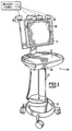
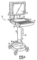
Fig. 1 is a perspective illustration of a medical work station; -
Fig. 2 is a front, perspective view of a medical work station; -
Fig. 3 is a rear, perspective view of a medical work station; -
Fig. 4 is a side, perspective view of a medical work station; and -
Fig. 5 is a side, perspective view of a medical work station; -
Fig. 6 is a perspective illustration of a medication dispensing cart; -
Fig. 7 illustrates a rear, perspective view of a medication dispensing -
Fig. 8 is a detailed, exploded, perspective view of the base of a medication dispensing cart, showing the battery in its cover being separated from the battery bracket on the base, according to an alternative embodiment of the present invention; -
Fig. 9 is a detailed, exploded, perspective view of the battery cover showing the battery inside, according to an alterantive embodiment of the present invention; -
Fig. 10 is a perspective, partially exploded view of the medication cart ofFig. 1 showing the cassette drawer system in relation to the cart itself, according to an embodiment of the present invention; -
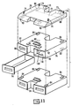
Fig. 11 is a perspective, detailed exploded view with two expanded detailed drawings of the cassette drawer arrangement, according to an embodiment of the present invention; -
Fig. 12 is a block diagram of various components of the medication cart system, according to an embodiment of the present invention; and -
Fig. 13 is a logic flow chart of various components of the medication cart system, according to an embodiment of the present invention.. - The present invention is a medical work station having a solar charging system. As shown in
FIGS. 1-5 , the medical work station includes a cart that carries a computer for providing access to and keeping track of medical information. The cart, as generally indicated inFIG. 1 byreference number 10, includes a variety of features and embodiments. Accordingly, the cart shown inFIG. 1 is merely exemplary and provided to place the present invention into context. Generally,cart 10 includes a computer/monitor 12, preferably with both a computer and a monitor in one unit with the computer behind the monitor and in the same housing. Computer/monitor 12 is equipped with a wireless network connection so that the user of thatcart 10 can communicate with a central administrator. Computer/monitor 12 also communicates with administrator without the active assistance of the user.Cart 10 also has awork surface 16 with a slide outkeyboard 18. Additionally,surface 16 is mounted on top of amast 24 carried in turn by a rollingbase 26. - The solar charging system of the present invention is operatively connected to the computer/
monitor 12 to provide a solar power input. This solar input provides a constant replenishing of power to the computer as long as there is a source of UV light, such as through inside lighting or through sunlight. For example and as illustrated, the solar charging system includes a plurality ofsolar panels 30 that are connected to the computer/monitor 12. This solar input provides a constant replenishing of power to the computer as long as there is a source of UV light, such as through inside lighting or through sunlight. As illustrated, thesolar panels 30 are located near the top of computer/monitor 12 and facing away from the user of the computer/monitor 12. - Optionally, the
solar panels 30 are rotatably connected to the computer/monitor 12 so that they can be ideally positioned for receiving a source of UV light. Additionally, thesolar panels 30 can be releasably connected to the computer/monitor 12 so that they can be both rotated and moved to optimum locations. - This configuration can be altered based on the conditions of a medical center and the length of the duty cycle. For example, a cart used in an emergency room where lighting is brighter around the clock as opposed to, say, a maternity ward, there may be sufficient lighting for a longer duty cycle and a smaller solar panel. A long term care facility may have even lower levels of lighting and shorter duty cycles. A reasonable amount of experimentation by those skilled at matching solar panel design with environment and duty cycle is required to optimize the panel design for the particular environment.
- Although amounts of power generated may vary according to the amount of a size of the
solar panels 30, the solar charging system of the present invention generates about 1 Amp of power indoors without input from natural light, and about 2 to about 3 Amps of power with the input of natural light. Preferably, the computer/monitor 12 of the workstation should not need recharging if it is operated at less than about 50% duty time. - As discussed, an important feature of the present invention is the use of a solar charging system in combination with a medical work station. The use of a solar charging system provides enhanced mobility to the work station, which no longer needs to be plugged into a power source. Additionally, the solar charging system extends the life of the work station as its power is constantly replenished by solar input.
- Computer/
monitor 12 of the present invention further includes anLCD screen 40 that draws less power than prior art monitors by such means as, for example, keeping the monitor at a modest size, reducing brightness but compensating by increasing contrast. Another important feature to the present invention includes the use of medical work station having a computer with anLCD screen 40 that draws a certain amount of power so as to provide an overall power reduction to the computer. In particular, theLCD screen 40 draws less than about 2 Amps of power, so that the computer requires less power input to operate. Moreover, theLCD screen 40 and solar charging system works in combination to enhance the efficiency and extend the life of the medical work station. With less overall power required to operate the computer, the computer's solar charging system functions all the more efficiently, as it will require less overall solar input to charge the computer. - As discussed, the present invention can be employed with any number of types of medical. An example of a medical cart that can be used in combination with the solar power system is now described.
- An exemplary cart is shown generally in
Fig. 6 byreference number 10. The cart includes a computer/monitor 12, preferably with both a computer and a monitor in one unit with the computer behind the monitor and in thesame housing 14.Cart 10 also has awork surface 16 with a slide outkeyboard 18. There is no security keypad; the keyboard's keypad serves for entry of codes to permit access.Work surface 16 is mounted on top of amast 24 carried in turn by a rollingbase 26.Work surface 16 can optionally include holders for storing items, such as antibacterial lotions and drinks, which the user may need when making rounds with thecart 10. - Referring to
Fig. 7 , there is illustrated a rear view of thepresent cart 10 showing computer/monitor 12,work surface 16,mast 24, and apower system 28, which is carried by rollingbase 26.Work surface 16 can further include hiddenUSB port 80 for use if additional electronic devices, such as scanners, need to be employed. Computer/monitor 12 is attached tomast 24 or underneath the work surface through amount 35 so that the entire top area of thework surface 16 is available to the user. Computer/monitor 12 is mounted using atiltable bracket 34 so that the angle of viewing computer/monitor 12 can be adjusted to suit the particular user. A clear hard covering is applied over the monitor portion of computer/monitor 12 in order to make computer/monitor less susceptible to scratches and impact. Preferably the covering is about a 1/8th inch thick and made of acrylic polymeric plastic or other suitable plastic polymer. -
Mast 24 is vertically adjustable so that the user can work seated or standing and users of different heights can work comfortably. Preferably,mast 24 is electronically adjustable by pressing abutton 29 rather than by turning a hand crank or other mechanical elevating mechanism. As shown inFig. 6 , themast 24 is telescoped, with anouter mast member 25 dimensioned to receive aninner mast member 23. This arrangement enables the raising and lowering of the computer/monitor 12 andwork surface 16. The raising and lowering of themast 24 can be controlled by anelectrical switch 29 that is connected to thepower system 28 and mechanical means (not shown), such as a screw/nut drive system that utilizes a number of small balls (ball screw). In operation, a user would press thebutton 29 in one direction, such as forward, to activate theelectrical switch 29 to lower themast 24, and in another direction, such as backward, to activate theelectrical switch 29 to raise themast 24. Theelectrical switch 29 provides input to thepower system 28, which controls the raising and lowering of themast 24 through an actuator connected to the mechanical means. Alternatively, the power system can also include a weight sensor connected to the actuator that can be used to override the raising and lowering ofmast 24 based on the weight of thework surface 16 and computer/monitor 12. For example, if the combined weight of thework surface 16 and computer/monitor 12 exceeds a preset, desired weight, the actuator will be tripped, and themast 24 will no longer be moveable through the use of thebutton 29. - An
alternative power system 28 is illustrated in further detail inFigs. 8-9 . If solar input is insufficient to power the medical cart, thepower system 28 can provide an alternative source of power as needed to ensure the constant operation of the medical cart. As shown,power system 28, which is connected throughmast 24 to computer/monitor 12, includes a power system controller (not shown) and abattery 27 that is carried in abattery bracket 50 held in rollingbase 26. As discussed, thebattery 27 can be charged in combination with thecart 10 or independently of thecart 10, through apower cord 31. Thus,work surface 16 further includes apower cord 31 plug rest 33 (shown inFig. 7 ) for conveniently storing thepower cord 31 when thecart 10 is being moved or is not in the vicinity of a power source.Battery 27 can be fixed tobattery bracket 50 with a variety of mechanical fasteners. In a preferred embodiment,battery 27 is fixed to battery bracket by twoscrews 52. By removingscrews 52,battery 27 and its associated electronics can be removed frombracket 50 to expose the wiring connections. Once the wiring connections are disconnected,battery 27 can be lifted free using itshandle 56.Battery 24 is still in acover 58 and may remain incover 58 during recharging. - In the
event battery 27 needs to be replaced altogether, thescrews 60 holdingbattery 27 in itscover 58 are removed, then the battery hold downscrews 62 are removed and finally,battery 27 can be disconnected and replaced. It will be clear that having both abattery cover 58 that stays withbattery 27 whilebattery 27 is either in service or being recharged, and whichbattery 27 and cover 58 can be quickly removed fromcart 10, makes it faster and easier to keep fully charged batteries oncarts 10. - As discussed,
battery 27 can be charged in combination with thecart 10 or independently of thecart 10, through apower cord 31. Thus,work surface 16 further includes apower cord 31plug rest 33 for conveniently storing thepower cord 31 when thecart 10 is being moved or is not in the vicinity of a power source. Additionally,power system 28 can be equipped with an LED indicator to show when thebatter 27 is charging and/or fully charged. -
Battery 27 is designed to last through at least one shift of eight hours before requiring recharging, preferably about 10 hours. In addition, each battery is connected to the balance ofcart 10 using a "Y"electrical connector 61 that permits a second, fully chargedbattery 27 to be connected (for "hot swapping") to the unused part of the Y connector, and then thefirst battery 28 can be removed from the battery bracket and disconnected from the Y connector without loss of power, or data, to computer/monitor 12, and the second battery can then be installed into the battery bracket. The connections that holdbattery 28 in its bracket are designed for quick release so battery change out takes but a few minutes at most. - Referring now to
Fig. 10 ,cart 10 according to the present invention includes acassette drawer system 41. As illustrated, at least onecassette drawer system 41 is carried belowwork surface 16. An exploded, detailed view of thecassette drawer system 41 is shown inFig. 11 .Cassette drawer system 41 is preferably modularized, and includes acassette drawer manager 70, which houses a cassette drawer controller andinterface 72 for monitoring the status and activities of cassette drawers and receiving input for computer/monitor 12. Thecassette drawer system 41 is generally connected towork surface 16 and wired to computer/monitor 12. More particularly, the top ofcassette drawer manager 70 is bolted towork surface 16. Accordingly,cassette drawer manager 70 includesbolt fasteners 74 along its top surface. Optionally,cassette drawer manager 70 includes a firstkey override lock 71 and a secondkey override lock 73. In the event drawers need to be opened, and thecassette drawer system 41 or the computer/monitor 12 system is malfunctioning, a first key from authorized users will override the cassettedrawer manager controller 72 to open the drawers containing certain medication. If narcotic medication needs to be accessed, a user must insert both a first key and a second key to open the narcotics-containing drawers. - Beneath
cassette drawer manager 70, at least onecassette drawer 76 is latched. Depending on the dimensions of thecassette drawer manager 70 and the cassette drawers, up to fourdrawers 76 can be added. An addeddrawer 76 cannot be released without opening the drawer. As soon as adrawer 76 is added, it is sensed by controller of computer/monitor 12 and cannot be opened except by a user with an authorizing pass code. - The latching mechanism between the
cassette drawer manager 70 and acassette drawer 76 will be the same as between a first cassette drawer and a second cassette drawer. This latching mechanism is shown in the expanded detailed drawings inFig. 11 . As between thecassette drawer manger 70 and a first cassette drawer, on the underside ofcassette drawer manager 70 are a plurality of dovetail-shapedcutout portions 80 that are dimensioned to receive dovetail-shapedprojections 84. Similarly, on the underside of eachcassette drawer 76 are a plurality of dovetail-shapedcutout portions 80 that are dimensioned to receive dovetail-shapedprojections 84 on every lower cassette drawer 78. In operation, dovetailprojections 84 simply slide intodovetail cutouts 80. - Once
cassette drawer 76 is seated fully intocassette drawer manager 70,spring tabs 90 having pins 91, which have been cut out from the bottom surface ofcassette drawer manager 70, are cammed upward asdrawer 76 is slid into place, and snap downward intocorresponding recesses 92 in the top surface ofdrawer 76. Pins 91 onspring tabs 90 will holddrawer 76 in place untildrawer 76 is opened by an authorized person who can then pulltabs 90 down torelease drawer 76 frommanager 70. Preferably, oncecassette drawer manager 70 and any and all additional cassettes are in place, thecassette drawer manager 70 and the cassette drawers are also electronically connected. - As illustrated,
cassette drawer manager 70 andcassette drawer 76 are generally U-shaped to facilitate engagement with themast 24. Eachcassette drawer 76 typically has at least twocompartments 94 that are independently lockable throughelectronic locks 100 and that have correspondingsensors 110.Sensors 110 determine if a drawer is open or closed, including of course when a drawer is left open or not fully closed. A drawer that is opened without authorization causes an alarm to sound and initiates an email to the system administrator. Alllocks 100 are software controlled rather than by using keys. For example, alock 100 could include a solenoid actuator connected to a lever and controlled by software. Keys can be lost or stolen or fall into the wrong hands. Furthermore, it is easier to change access pass codes using software than to re-key locks. Computer/monitor 12 can be programmed to lock every drawer unless unlocked by a person with the correct level of authorization who enters the correct pass code viakeyboard 18. Access to acompartment 94 containing narcotics requires two pass codes; otherwise one pass code unlocks acompartment 94. Each user has his or her own pass code or codes so the user who accesses each drawer is known by the pass code used, as well as the time and date of the access by that user. -
Cart 10 is optionally provided with a plug in scanner for reading medication containers and automatically and accurately loading drawers and the computer database with the correct information about the medications being loaded into each drawer. In this way, the system administrator can have a real time inventory of medications in all carts in its system, knowing exactly what type and how much medication is in each drawer of each cart -
Cassette drawer system 41 also has an optional utility cassette 78, which can be used to store such items as rubber gloves, paper cups, tissues, and so forth. Because a utility cassette 78 need not be secured,cassette drawer manager 70 automatically deactivatessensors 110 andlocks 100 of utility cassette drawers 78 that become part of thecassette drawer system 30. - A block diagram of the operating system for the
cart 10 is shown inFig. 12 . As illustrated, computer/monitor 12 includes a computer controller andinterface logic 200 that receives computer controller input and generates computer controller output. For example,computer controller 200 process user input, such as the identity of user, the biometric information of user, pass codes entered by user. Furthermore, computer controller provides output tocassette drawer system 41 relating to the designation of cassette drawers included in thecassette drawer system 41. Significantly, computer/monitor 12 can, in real time, inventory medication as it is loaded and as it used, as well as which user is dispensing the medication. Additionally, computer/monitor 12 is equipped with a wireless network connection, preferably through SMTP (simple mail transfer protocol) so that the user of thatcart 10 can communicate with acentral administrator 400. Computer/monitor 12 also communicates withadministrator 400 without the active assistance of the user. Accordingly, the status and whereabouts of thecart 10 can be constantly and effectively monitored through wireless communication. - As previously described, the
cassette drawer system 41 also includes cassette drawer controller andinterface logic 500. This cassette drawer controller receives input from the computer controller about the cassette drawers and their designations. Cassette drawer controller, therefore, can lock and unlock drawers based on this input. Furthermore, the cassette drawer controller logs what the drawers do, including when they are opened and by whom. Accordingly, thecassette drawer system 41 has the ability to monitor itself. Similarly, thepower system 28 also includes controller andinterface logic 600, which monitors the condition ofbattery 27, and controls the raising and lowering of themast 24. For example, the condition of thebattery 27 when low or when the unit is turning off due to low battery power, power system controller communicates these conditions to computer controller, which in turn reports by email to the administrator. Computer/monitor 12 will also automatically report by email an attempt to break intocart 10, a log of the charging system, a log of the times and the identities of users who have accessed each cassette drawer. Other information can also be reported - To summarize an embodiment of the logic for the medication cart system,
Fig. 13 includes of flow chart. As shown, at 700, a decision is made bymedication cart 10 whether thebattery 27 is suitable. If thebattery 27 is not in a good condition and if communication is required at 701 as to the status of thebattery 27, an electronic communication is sent to central administrator at 702. If maintenance is needed, thebattery 27 will be charged or replaced at 703. If thebattery 27 is in good condition and communication is required at 704, an electronic communication is sent to central administrator at 705. - At 706, a decision is made as to whether medication must be dispensed or refilled. If narcotic medication must be dispensed or refilled at 707, the narcotics drawer is unlocked with two pass codes at 709. If communication as to the status of the narcotics drawer is required at 710, an electronic communication is sent to central administrator at 711. If non-narcotic medication must be dispensing or refilling at 712, the medication drawer is unlocked with on pass code at 713. If communication as to the status of the medication drawer is required at 714, an electronic communication is sent to central administrator at 715. If a utility drawer needs to be accessed at 716, the utility drawer is unlocked with no need for a pass code at 717. If communication as to the status of the utility drawer is required at 718, an electronic communication is sent to central administrator at 719.
- If user adds or subtracts a cassette drawer from the
cassette drawer system 41 at 720 and communication is required as to the status of thecassette drawer system 41 at 721, an electronic communication is sent to central administrator at 722. If, on the other hand, an unauthorized access to thecassette drawer system 41 is attempted or accomplished at 730, and communication is required as to the status of thecassette drawer system 41 at 731, an electronic communication is sent to central administrator at 732.
Claims (16)
- A system comprising a medical work station including a cart (10) having a computer (12) and a battery (27), wherein said computer (12) includes a monitor, and the cart (10) further comprises a rolling base (26), a mast (24) extending generally vertically up from the rolling base (26), a work surface (16) operably coupled to the mast (24) wherein the battery (27) is included within the rolling base (26), characterized in that a solar charging system is operatively connected to said medical work station, wherein said solar charging system has a solar power input that provides a constant replenishing of power to said computer (12) as long as there is a source of UV light, and at least one cassette drawer system (41) is wired to the computer (12) and carried below the work surface (16), wherein the cassette drawer system (41) is modularized and contains a cassette drawer manager (70) and at least one cassette drawer (76), the cassette drawer manager (70) and the at least one cassette drawer (76) being generally U-shaped for an engagement with the mast (24).
- The system as recited in claim 1, characterized in that a central administrator is operatively connected to said computer (12).
- The system as recited in claim 2, characterized in that said computer (12) has wireless network connection for communicating with said central administrator.
- The system as recited in claim 3, characterized in that said computer (12) communicates with said central administrator without the active assistance of the user.
- The system as recited in claim 1, characterized in that said solar charging system includes a plurality of solar panels (30) that are connected to said computer (12).
- The system as recited in claim 5, characterized in that each of said plurality of solar panels (30) is rotatably connected to said computer (12).
- The system as recited in claim 5, characterized in that each of said plurality of solar panels (30) is releasably connected to said computer (12).
- The system as recited in claim 1, characterized in that said solar charging system generates about 1 Amp of power indoors without input from natural light.
- The system as recited in claim 1, characterized in that said solar charging system generates about 2 to about 3 Amps of power with the input of natural light.
- The system as recited in claim 1, characterized in that said solar charging system generates sufficient power to avoid recharging said computer (12) if it is operated at less than about 50 % duty time.
- The system as recited in claim 1, characterized in that said monitor includes an LCD screen (40), that draws less than about 2 Amps of power.
- The system as recited in any of the preceding claims, characterized in that the battery (27) is removable by means of a handle (56).
- The system as recited in any of the preceding claims, characterized in that the height of the mast (24) is electronically adjustable by pressing a button (29) or mechanically adjustable by turning a hand crank or another mechanical elevating mechanism.
- The system as recited in any of the preceding claims, characterized in that each cassette drawer (76) has at least two compartments (94) that are independently lockable through electronic locks (100) and that have corresponding sensors (110).
- The system as recited in any of the preceding claims, characterized in that said computer (12) is programmed to lock every cassette drawer (76) unless unlocked by a person with a correct level of authorization.
- The system as recited in any of the preceding claims, characterized in that said cassette drawer manager (70) houses a cassette drawer controller and interface (72) for monitoring the status and activities of cassette drawers (70).
Applications Claiming Priority (2)
| Application Number | Priority Date | Filing Date | Title |
|---|---|---|---|
| US83910406P | 2006-08-21 | 2006-08-21 | |
| PCT/US2007/076336 WO2008024722A2 (en) | 2006-08-21 | 2007-08-20 | Solar charged mobile working stations |
Publications (3)
| Publication Number | Publication Date |
|---|---|
| EP2054936A2 EP2054936A2 (en) | 2009-05-06 |
| EP2054936A4 EP2054936A4 (en) | 2012-11-21 |
| EP2054936B1 true EP2054936B1 (en) | 2016-07-20 |
Family
ID=39107570
Family Applications (1)
| Application Number | Title | Priority Date | Filing Date |
|---|---|---|---|
| EP07814264.3A Active EP2054936B1 (en) | 2006-08-21 | 2007-08-20 | Solar charged mobile working stations |
Country Status (5)
| Country | Link |
|---|---|
| US (1) | US8378620B2 (en) |
| EP (1) | EP2054936B1 (en) |
| CA (1) | CA2661516C (en) |
| ES (1) | ES2599211T3 (en) |
| WO (1) | WO2008024722A2 (en) |
Families Citing this family (30)
| Publication number | Priority date | Publication date | Assignee | Title |
|---|---|---|---|---|
| US20060125356A1 (en) * | 2004-12-03 | 2006-06-15 | Mckesson Automation Inc. | Mobile point of care system and associated method and computer program product |
| TW201010244A (en) * | 2008-08-27 | 2010-03-01 | Pegatron Corp | Solar charging device and method |
| DE102008048263B3 (en) * | 2008-09-22 | 2010-05-20 | Fresenius Medical Care Deutschland Gmbh | A bracket for releasably receiving a device on a medical device, and corresponding medical device |
| KR101521934B1 (en) * | 2009-03-19 | 2015-05-28 | 엘지전자 주식회사 | A mobile terminal and its display control method |
| USD669992S1 (en) | 2010-05-20 | 2012-10-30 | Sound Surgical Technologies, Llc | Ultrasonic amplifier |
| USD669993S1 (en) | 2010-09-29 | 2012-10-30 | Sound Surgical Technologies, Llc | Console for use in power assisted lipoplasty |
| WO2012078611A1 (en) * | 2010-12-06 | 2012-06-14 | Omnicell, Inc. | Computer controlled and monitored medical storage system |
| US9042607B2 (en) | 2011-05-02 | 2015-05-26 | Omnicell, Inc. | System and method for user access of dispensing unit |
| CA2873262A1 (en) * | 2012-05-11 | 2013-11-14 | Ameriwood Industries, Inc. | Television mounting device |
| USD727842S1 (en) * | 2012-08-03 | 2015-04-28 | Soitec Solar Gmbh | Moveable carrier for photovoltaic modules |
| WO2014033588A1 (en) * | 2012-09-03 | 2014-03-06 | Norometrika Medikal Tip Teknolojileri Saglik Yazilim Donanim Ve Danismanlik Sanayi Ve Ticaret Limited Sirketi | Stimulation and response monitoring in functional magnetic resonance imaging |
| BR112015011514B1 (en) | 2012-11-19 | 2022-01-25 | Omnicell, Inc | Cabinet system and method for monitoring items having an RFID tag |
| SG11201506863VA (en) | 2013-03-01 | 2015-09-29 | Intermetro Corp | Mobile computer workstation |
| US9471953B1 (en) * | 2013-07-27 | 2016-10-18 | Gregory Leon Crowe | Digital sports table |
| US9711765B1 (en) | 2014-01-17 | 2017-07-18 | Ultralife Corporation | Rapid replacement battery system |
| GB2557464A (en) * | 2015-03-17 | 2018-06-20 | Zioxi Ltd | Rechargeable furniture leg |
| CN106309063A (en) * | 2015-07-02 | 2017-01-11 | 周宝龙 | Medical nursing trolley |
| JP2017012622A (en) * | 2015-07-03 | 2017-01-19 | 株式会社岡村製作所 | Cart equipment |
| US10515722B2 (en) | 2015-10-15 | 2019-12-24 | Omnicell, Inc. | Medical equipment with diversion mechanism |
| ES2904497T3 (en) * | 2015-11-13 | 2022-04-05 | Humanscale Corp | A station of medical technology and method of use |
| US10239613B2 (en) * | 2017-01-23 | 2019-03-26 | Ameristar Solar, LLC | Solar power tethered drone |
| AT16581U1 (en) * | 2018-03-08 | 2020-01-15 | Dagmar Koeberl | Multifunctional device |
| EP3820424A4 (en) * | 2018-07-09 | 2022-04-06 | Green Cubes Technology Corporation | BATTERY POWERED MOBILE MEDICAL CART |
| IL272830B2 (en) * | 2020-02-20 | 2024-08-01 | Momentis Surgical Ltd | A cart for positioning a surgical robot |
| USD1003294S1 (en) | 2020-03-05 | 2023-10-31 | Accutronics, Ltd. | Docking cradle |
| USD977416S1 (en) | 2020-03-05 | 2023-02-07 | Accutronics, Ltd | Battery |
| USD1122185S1 (en) | 2020-03-05 | 2026-04-14 | Accutronics, Ltd | Battery contacts |
| USD978073S1 (en) | 2020-03-05 | 2023-02-14 | Accutronics, Ltd | Combined battery and docking cradle |
| US11460147B2 (en) * | 2020-08-25 | 2022-10-04 | Ningbo Tuotuo River Design Company | Multifunction display stands |
| WO2023100091A1 (en) * | 2021-12-01 | 2023-06-08 | Kamble Aanand Prakash | A system for a portable workstation-and-recreational unit and a method to operate the same |
Citations (2)
| Publication number | Priority date | Publication date | Assignee | Title |
|---|---|---|---|---|
| US5806943A (en) * | 1996-09-12 | 1998-09-15 | Sculptor Developmental Technologies, Inc. | Mobile workstation |
| WO2006020862A2 (en) * | 2004-08-13 | 2006-02-23 | Welch Allyn, Inc. | Mobile medical workstation |
Family Cites Families (102)
| Publication number | Priority date | Publication date | Assignee | Title |
|---|---|---|---|---|
| US4336964A (en) * | 1978-11-24 | 1982-06-29 | American Microcar Incorporated | Lightweight canopy for three-wheeled vehicle with low center of gravity |
| SE417549B (en) * | 1979-08-29 | 1981-03-23 | Hasselblad Ab Victor | DIAPROJECTOR WITH FIXED IMAGE MAGAZINE AND AUTOMATIC IMAGE CHANGE DEVICE |
| US4372515A (en) * | 1980-09-08 | 1983-02-08 | Xerox Corporation | CRT Housing support and rocking tilt apparatus |
| DE8114991U1 (en) | 1981-05-20 | 1981-10-08 | Robert Krause KG Zweigniederlassung Weilheim/Teck, 7315 Weilheim | WORK TABLE |
| US4368867A (en) * | 1981-06-29 | 1983-01-18 | Honeywell Information Systems Inc. | Tilt base for a CRT display terminal |
| US4697928A (en) * | 1981-08-31 | 1987-10-06 | Northern Lights Trust Of February 14, 1978 | Modular mixing apparatus including interchangeable fluid processing means |
| USD279007S (en) * | 1982-06-01 | 1985-05-28 | Fortune Systems Corporation | Adjustable computer display and base |
| US4616218A (en) * | 1983-01-03 | 1986-10-07 | International Business Machines Corporation | Adjustable CRT display |
| US4471931A (en) * | 1983-03-18 | 1984-09-18 | Teletype Corporation | CRT Monitor tilt mechanism |
| US4575033A (en) * | 1983-04-04 | 1986-03-11 | Honeywell Information Systems Inc. | Tilt-swivel base for a CRT display terminal |
| EP0145410A3 (en) | 1983-12-05 | 1987-05-13 | Hauserman Inc. | Adjustable work station and accessories therefor |
| US4589621A (en) * | 1984-01-03 | 1986-05-20 | International Business Machines Corporation | Ergonomic monitor stand |
| US4556189A (en) * | 1984-02-06 | 1985-12-03 | At&T Teletype Corporation | CRT Monitor tilt mechanism |
| USD289873S (en) * | 1984-04-20 | 1987-05-19 | Apple Computer, Inc. | Flat panel display for personal computer |
| US4561620A (en) * | 1984-05-03 | 1985-12-31 | International Business Machines Corp. | Tiltable cathode ray tube display device structure |
| US4640199A (en) * | 1985-03-15 | 1987-02-03 | Zigman Donald J | Mobile terminal mounting stand |
| US4645153A (en) * | 1985-05-23 | 1987-02-24 | Ncr Corporation | Tilt and swivel support |
| USD295415S (en) * | 1985-11-15 | 1988-04-26 | American Telephone And Telegraph Company, At&T Bell Laboratories | Adjustable support for plasma display panel |
| USD293382S (en) * | 1985-11-19 | 1987-12-22 | Modern Royal Co., Ltd. | Lighter or the like |
| US4726633A (en) * | 1986-03-18 | 1988-02-23 | Symbolics Inc. | Tiltable monitor |
| GB2189210B (en) * | 1986-04-19 | 1990-03-21 | Ibm | Counterbalanced support |
| US4769634A (en) * | 1986-05-12 | 1988-09-06 | Digital Equipment Corporation | Tilt apparatus for cathode ray tube display |
| US4717112A (en) * | 1986-11-04 | 1988-01-05 | Pirkle Fred L | Computer workstation |
| US4852500A (en) * | 1987-03-18 | 1989-08-01 | Herman Miller, Inc. | Integrated computer implement work area |
| US4836486A (en) * | 1987-04-16 | 1989-06-06 | Anthro Corporation | Adjustable support |
| US4834329A (en) * | 1987-05-29 | 1989-05-30 | Michael Delapp | Monitor support for a terminal |
| US4836478A (en) * | 1987-10-15 | 1989-06-06 | Ergotron, Inc. | Suspension system for personal computers and monitors |
| EP0321137A3 (en) | 1987-12-18 | 1989-12-20 | HILL-ROM COMPANY, INC. (an Indiana corporation) | Computer cart |
| US4967928A (en) * | 1988-06-09 | 1990-11-06 | Carter Cheryl L | Inventory control including individual patient listing and medical chart record for medication cart |
| USD312630S (en) * | 1988-06-30 | 1990-12-04 | Next, Inc. | Computer monitor and stand |
| USD310358S (en) * | 1988-09-07 | 1990-09-04 | Bell & Howell Publication Systems Company | Combined monitor and process or for computer work station or similar article |
| USD317912S (en) * | 1988-11-29 | 1991-07-02 | Oki Electric Industry Co., Ltd. | Video display |
| JPH0283640U (en) * | 1988-12-09 | 1990-06-28 | ||
| US4918841A (en) * | 1989-01-30 | 1990-04-24 | Turner Jerome P | Athletic shoe with improved midsole |
| US4919387A (en) * | 1989-03-06 | 1990-04-24 | Bell & Howell Publication Systems Company | Tilt and swivel support apparatus |
| USD319405S (en) * | 1989-03-16 | 1991-08-27 | Homestar International, Inc. | Tape measure with a digital display |
| USD319435S (en) * | 1989-04-20 | 1991-08-27 | Northern Telecom Limited | Data display |
| US5174223A (en) * | 1989-09-20 | 1992-12-29 | Nagy Marta K | Ergonomically designed computer workstation adjustable to various sitting and standing positions |
| US5041770A (en) * | 1989-11-16 | 1991-08-20 | Seiler Michael A | Apparatus for adjusting a computer work station to individual needs |
| US4989291A (en) * | 1990-03-08 | 1991-02-05 | Alternative Resources Corporation | Computer servicing cart |
| USD326847S (en) * | 1990-05-15 | 1992-06-09 | International Business Machines Corporation | Flat panel display with a tilt swivel base |
| USD344933S (en) * | 1991-03-26 | 1994-03-08 | International Business Machines Corporation | Display |
| USD339796S (en) * | 1991-04-30 | 1993-09-28 | International Business Machines Corporation | Combined flat panel display and folding stand with user interface control and stylus therefor |
| US5321579A (en) * | 1991-07-19 | 1994-06-14 | Teknion Furniture Systems | Office panelling system with a monitor screen mounted on a cantilevered adjustable arm |
| USD337104S (en) * | 1991-08-15 | 1993-07-06 | Ncr Corporation | Flat screen display terminal |
| CN2100660U (en) * | 1991-08-31 | 1992-04-01 | 马希光 | Rechargeable Solar Computer |
| USD348449S (en) * | 1991-09-20 | 1994-07-05 | International Business Machines Incorporated | Flat panel display |
| US5772637A (en) * | 1995-06-07 | 1998-06-30 | Deka Products Limited Partnership | Intravenous-line flow-control system |
| JPH05161510A (en) | 1991-12-16 | 1993-06-29 | Sekisui Chem Co Ltd | Bed side table |
| US5212628A (en) * | 1992-01-17 | 1993-05-18 | The I.D.E.A. Corporation | Modular portable work station having a movable support tray |
| US5287815A (en) * | 1992-05-07 | 1994-02-22 | Milton Gross | Computer workstation |
| USD349449S (en) * | 1992-05-25 | 1994-08-09 | Norden Pac Development Ab | Tube |
| US5362025A (en) * | 1992-06-15 | 1994-11-08 | Michael Trom | Portable computer support device and means of support |
| US5277392A (en) * | 1992-10-19 | 1994-01-11 | Curtis Manufacturing Company, Inc. | Adjustable computer monitor arm and method |
| USD354952S (en) * | 1992-11-20 | 1995-01-31 | International Business Machines Corp. | Flat panel display with a palm rest |
| USD354052S (en) * | 1992-12-25 | 1995-01-03 | International Business Machines Corp. | Video display |
| USD349489S (en) * | 1993-03-09 | 1994-08-09 | Wang Jing Y | LCD monitor |
| USD357468S (en) * | 1993-04-17 | 1995-04-18 | International Business Machines Corporation | Flat panel computer monitor |
| US5437235A (en) * | 1993-06-10 | 1995-08-01 | Symbiote, Inc. | Computer work station |
| US5522323A (en) * | 1993-08-24 | 1996-06-04 | Richard; Paul E. | Ergonimic computer workstation and method of using |
| US5473997A (en) * | 1993-09-09 | 1995-12-12 | Am Fab, Inc. | Overbed table with single bar cantilever support |
| US5536084A (en) * | 1994-05-09 | 1996-07-16 | Grandview Hospital And Medical Center | Mobile nursing unit and system therefor |
| USD383000S (en) * | 1994-08-11 | 1997-09-02 | Fendi Paola & S.Lle S.A.S. | Clasp for purses and handbags |
| CH688607A5 (en) | 1995-02-07 | 1997-12-15 | Langhans & Schondelmaier Ag | Work station with at least two planes, esp. for use as computer work station lever arm carrying it so that movements of first plane are tracked up or down by tilting movements of second plane |
| US5738316A (en) * | 1995-04-03 | 1998-04-14 | Ergotron, Inc. | Vertical work center |
| DE29506433U1 (en) | 1995-04-13 | 1995-08-31 | Meier, Hans-Bernd, 76684 Östringen | Reading stand with LCD / flat screen holder (LCD / flat screen stand) |
| US5630566A (en) * | 1995-05-30 | 1997-05-20 | Case; Laura | Portable ergonomic work station |
| US5694199A (en) * | 1995-09-27 | 1997-12-02 | Rodriguez; Edgar R. | Method and apparatus for performing automated vision performance tests |
| DE19536664C2 (en) | 1995-09-30 | 1998-04-30 | Desanta | Computer desk |
| US5775234A (en) * | 1995-10-12 | 1998-07-07 | Bissell Inc. | Height adjustable overbed table and locking device therefor |
| USD377720S (en) * | 1996-01-26 | 1997-02-04 | Bush Industries, Inc. | Laptop computer cart |
| DE59703929D1 (en) | 1996-03-03 | 2001-08-09 | Bucher Leichtbau Ag Faellanden | Office workplace with communication devices |
| JP3588903B2 (en) | 1996-03-29 | 2004-11-17 | 株式会社岡村製作所 | Computer table |
| JP3581512B2 (en) | 1996-04-25 | 2004-10-27 | キヤノン株式会社 | Information processing equipment |
| USD393382S (en) * | 1996-06-03 | 1998-04-14 | Tiffany Industries, Inc. | Adjustable height computer workstation |
| US5842672A (en) | 1996-06-07 | 1998-12-01 | Ergotron, Inc. | Mounting system for flat panel display, keyboard and stand |
| US5687717A (en) * | 1996-08-06 | 1997-11-18 | Tremont Medical, Inc. | Patient monitoring system with chassis mounted or remotely operable modules and portable computer |
| DE19642425A1 (en) | 1996-10-15 | 1998-04-16 | Martin Dipl Ing Frigger | Free standing computer work station |
| US5868079A (en) * | 1996-10-16 | 1999-02-09 | Finish Group Ltd. | Stand for a monitor and a keyboard |
| JPH1057157A (en) | 1996-11-20 | 1998-03-03 | Itoki Crebio Corp | Wagon desk for mounting a personal computer with a lifting table |
| JPH10146224A (en) | 1996-11-21 | 1998-06-02 | Takanashi Sangyo Kk | Desk for PC |
| US5822185A (en) * | 1996-12-06 | 1998-10-13 | Dell U.S.A., L.P. | Ergonomic docking station for a portable computer |
| US5960901A (en) * | 1997-09-04 | 1999-10-05 | Corbin Pacific, Inc. | Battery-powered vehicle |
| US5897179A (en) * | 1997-09-30 | 1999-04-27 | Western Auto Supply Company | Apparatus for mounting computer equipment |
| JPH11127976A (en) | 1997-10-24 | 1999-05-18 | Takeo Watanabe | Rack with monitor mounting plate angle adjustment function |
| US5971341A (en) * | 1997-11-05 | 1999-10-26 | Pfister; Joel W. | Adjustable leg system |
| FI108774B (en) | 1997-12-03 | 2002-03-28 | Abb Corporate Res Oy | Workstation |
| US6098936A (en) * | 1998-02-23 | 2000-08-08 | Birrell; Andrew | Portable ergonomic work station |
| US6085972A (en) * | 1998-04-30 | 2000-07-11 | Ncr Corporation | Retail terminal having a tilt mechanism which includes a ratchet member for positioning a display monitor relative to a stationary base |
| US6219587B1 (en) * | 1998-05-27 | 2001-04-17 | Nextrx Corporation | Automated pharmaceutical management and dispensing system |
| US6029580A (en) * | 1998-07-09 | 2000-02-29 | Dell Usa, L.P. | Hanging support basket for computers |
| US6061104A (en) * | 1998-07-22 | 2000-05-09 | Silicon Graphics, Inc. | Flat panel display and stand with vertical adjustment and tilt adjustment |
| US6816145B1 (en) * | 1998-07-22 | 2004-11-09 | Silicon Graphics, Inc. | Large area wide aspect ratio flat panel monitor having high resolution for high information content display |
| US6493220B1 (en) * | 1998-09-18 | 2002-12-10 | Lxe, Inc. | Mobile clinical workstation |
| US6269753B1 (en) * | 1998-10-26 | 2001-08-07 | Allison C. Roddan | Cantilevered, adjustable, portable computer desk |
| US6298794B1 (en) * | 1999-08-26 | 2001-10-09 | Microsphere Inc. | Ergonomic computer workstation |
| US6394402B2 (en) * | 1999-09-01 | 2002-05-28 | Stinger Industries, Llc | Vertically adjustable mobile computer workstation |
| US6199952B1 (en) * | 1999-09-14 | 2001-03-13 | Hon Technology Inc. | Chair control gas spring retainer for chair height reduction |
| JP2001178017A (en) * | 1999-12-15 | 2001-06-29 | Nec Corp | Battery pack and its charging circuit |
| US20060005876A1 (en) * | 2000-04-27 | 2006-01-12 | Russell Gaudiana | Mobile photovoltaic communication facilities |
| US20060125356A1 (en) * | 2004-12-03 | 2006-06-15 | Mckesson Automation Inc. | Mobile point of care system and associated method and computer program product |
| WO2007095222A2 (en) * | 2006-02-11 | 2007-08-23 | Rioux Vision, Inc. | Medication dispensing cart |
-
2007
- 2007-08-20 EP EP07814264.3A patent/EP2054936B1/en active Active
- 2007-08-20 ES ES07814264.3T patent/ES2599211T3/en active Active
- 2007-08-20 US US12/438,341 patent/US8378620B2/en active Active
- 2007-08-20 WO PCT/US2007/076336 patent/WO2008024722A2/en not_active Ceased
- 2007-08-20 CA CA2661516A patent/CA2661516C/en active Active
Patent Citations (2)
| Publication number | Priority date | Publication date | Assignee | Title |
|---|---|---|---|---|
| US5806943A (en) * | 1996-09-12 | 1998-09-15 | Sculptor Developmental Technologies, Inc. | Mobile workstation |
| WO2006020862A2 (en) * | 2004-08-13 | 2006-02-23 | Welch Allyn, Inc. | Mobile medical workstation |
Also Published As
| Publication number | Publication date |
|---|---|
| WO2008024722A3 (en) | 2008-12-11 |
| ES2599211T3 (en) | 2017-01-31 |
| WO2008024722A2 (en) | 2008-02-28 |
| EP2054936A2 (en) | 2009-05-06 |
| EP2054936A4 (en) | 2012-11-21 |
| CA2661516A1 (en) | 2008-02-28 |
| US8378620B2 (en) | 2013-02-19 |
| CA2661516C (en) | 2016-09-13 |
| US20110006724A1 (en) | 2011-01-13 |
Similar Documents
| Publication | Publication Date | Title |
|---|---|---|
| CA2661516C (en) | Solar charged mobile working stations | |
| US8180485B2 (en) | Medication dispensing cart | |
| US20070228680A1 (en) | Modular Workstation | |
| EP2649595B1 (en) | Medication dispensing cart | |
| US7855530B2 (en) | Battery charging system and method of reducing variation in battery charging cycle count | |
| US8169191B2 (en) | System for use in gathering or processing data in a healthcare facility having fleet of mobile workstations | |
| US8775828B2 (en) | Power control system for mobile workstation and method | |
| US7782607B2 (en) | Mobile workstation having power system with removable battery configured for drop-in engagement therewith | |
| US8227943B2 (en) | Power system retrofit kit for mobile workstation and retrofit method | |
| AU2014223792B2 (en) | Mobile computer workstation | |
| US20090261656A1 (en) | Power system for mobile workstation and method | |
| US20260139896A1 (en) | Dispensing system with temperature controlled drawers | |
| US8160727B2 (en) | Mobile workstation control system configured for power system and peripheral device control | |
| EP3013720A1 (en) | Secure medication transport | |
| US7830668B2 (en) | Power supply unit for mobile workstation and method |
Legal Events
| Date | Code | Title | Description |
|---|---|---|---|
| PUAI | Public reference made under article 153(3) epc to a published international application that has entered the european phase |
Free format text: ORIGINAL CODE: 0009012 |
|
| 17P | Request for examination filed |
Effective date: 20090227 |
|
| AK | Designated contracting states |
Kind code of ref document: A2 Designated state(s): AT BE BG CH CY CZ DE DK EE ES FI FR GB GR HU IE IS IT LI LT LU LV MC MT NL PL PT RO SE SI SK TR |
|
| AX | Request for extension of the european patent |
Extension state: AL BA HR MK RS |
|
| DAX | Request for extension of the european patent (deleted) | ||
| A4 | Supplementary search report drawn up and despatched |
Effective date: 20121019 |
|
| RIC1 | Information provided on ipc code assigned before grant |
Ipc: H02J 7/00 20060101ALI20121015BHEP Ipc: H01L 31/00 20060101ALI20121015BHEP Ipc: H02N 6/00 20060101ALI20121015BHEP Ipc: H01L 31/042 20060101ALI20121015BHEP Ipc: G08B 7/00 20060101ALI20121015BHEP Ipc: G08B 3/00 20060101ALI20121015BHEP Ipc: G08B 5/00 20060101ALI20121015BHEP Ipc: H01L 25/00 20060101AFI20121015BHEP |
|
| 17Q | First examination report despatched |
Effective date: 20130307 |
|
| GRAP | Despatch of communication of intention to grant a patent |
Free format text: ORIGINAL CODE: EPIDOSNIGR1 |
|
| RIC1 | Information provided on ipc code assigned before grant |
Ipc: H01L 25/00 20060101AFI20160118BHEP Ipc: H02S 99/00 20140101ALI20160118BHEP Ipc: A61G 12/00 20060101ALI20160118BHEP Ipc: A61B 5/00 20060101ALI20160118BHEP Ipc: H01L 31/042 20060101ALI20160118BHEP Ipc: G08B 7/00 20060101ALI20160118BHEP Ipc: G08B 5/00 20060101ALI20160118BHEP Ipc: H01L 31/00 20060101ALI20160118BHEP Ipc: G06F 1/26 20060101ALI20160118BHEP Ipc: G08B 3/00 20060101ALI20160118BHEP Ipc: G06F 19/00 20110101ALI20160118BHEP Ipc: H02J 7/00 20060101ALI20160118BHEP |
|
| INTG | Intention to grant announced |
Effective date: 20160203 |
|
| GRAS | Grant fee paid |
Free format text: ORIGINAL CODE: EPIDOSNIGR3 |
|
| GRAA | (expected) grant |
Free format text: ORIGINAL CODE: 0009210 |
|
| AK | Designated contracting states |
Kind code of ref document: B1 Designated state(s): AT BE BG CH CY CZ DE DK EE ES FI FR GB GR HU IE IS IT LI LT LU LV MC MT NL PL PT RO SE SI SK TR |
|
| REG | Reference to a national code |
Ref country code: GB Ref legal event code: FG4D |
|
| REG | Reference to a national code |
Ref country code: CH Ref legal event code: EP Ref country code: FR Ref legal event code: PLFP Year of fee payment: 10 |
|
| REG | Reference to a national code |
Ref country code: IE Ref legal event code: FG4D |
|
| REG | Reference to a national code |
Ref country code: AT Ref legal event code: REF Ref document number: 814690 Country of ref document: AT Kind code of ref document: T Effective date: 20160815 |
|
| REG | Reference to a national code |
Ref country code: DE Ref legal event code: R096 Ref document number: 602007047105 Country of ref document: DE |
|
| RAP2 | Party data changed (patent owner data changed or rights of a patent transferred) |
Owner name: OMNICELL, INC. |
|
| REG | Reference to a national code |
Ref country code: LT Ref legal event code: MG4D |
|
| REG | Reference to a national code |
Ref country code: NL Ref legal event code: MP Effective date: 20160720 |
|
| REG | Reference to a national code |
Ref country code: AT Ref legal event code: MK05 Ref document number: 814690 Country of ref document: AT Kind code of ref document: T Effective date: 20160720 |
|
| PG25 | Lapsed in a contracting state [announced via postgrant information from national office to epo] |
Ref country code: BE Free format text: LAPSE BECAUSE OF NON-PAYMENT OF DUE FEES Effective date: 20160831 |
|
| PG25 | Lapsed in a contracting state [announced via postgrant information from national office to epo] |
Ref country code: NL Free format text: LAPSE BECAUSE OF FAILURE TO SUBMIT A TRANSLATION OF THE DESCRIPTION OR TO PAY THE FEE WITHIN THE PRESCRIBED TIME-LIMIT Effective date: 20160720 Ref country code: IT Free format text: LAPSE BECAUSE OF FAILURE TO SUBMIT A TRANSLATION OF THE DESCRIPTION OR TO PAY THE FEE WITHIN THE PRESCRIBED TIME-LIMIT Effective date: 20160720 Ref country code: IS Free format text: LAPSE BECAUSE OF FAILURE TO SUBMIT A TRANSLATION OF THE DESCRIPTION OR TO PAY THE FEE WITHIN THE PRESCRIBED TIME-LIMIT Effective date: 20161120 Ref country code: FI Free format text: LAPSE BECAUSE OF FAILURE TO SUBMIT A TRANSLATION OF THE DESCRIPTION OR TO PAY THE FEE WITHIN THE PRESCRIBED TIME-LIMIT Effective date: 20160720 Ref country code: LT Free format text: LAPSE BECAUSE OF FAILURE TO SUBMIT A TRANSLATION OF THE DESCRIPTION OR TO PAY THE FEE WITHIN THE PRESCRIBED TIME-LIMIT Effective date: 20160720 |
|
| REG | Reference to a national code |
Ref country code: ES Ref legal event code: FG2A Ref document number: 2599211 Country of ref document: ES Kind code of ref document: T3 Effective date: 20170131 |
|
| PG25 | Lapsed in a contracting state [announced via postgrant information from national office to epo] |
Ref country code: AT Free format text: LAPSE BECAUSE OF FAILURE TO SUBMIT A TRANSLATION OF THE DESCRIPTION OR TO PAY THE FEE WITHIN THE PRESCRIBED TIME-LIMIT Effective date: 20160720 Ref country code: BE Free format text: LAPSE BECAUSE OF FAILURE TO SUBMIT A TRANSLATION OF THE DESCRIPTION OR TO PAY THE FEE WITHIN THE PRESCRIBED TIME-LIMIT Effective date: 20160720 Ref country code: LV Free format text: LAPSE BECAUSE OF FAILURE TO SUBMIT A TRANSLATION OF THE DESCRIPTION OR TO PAY THE FEE WITHIN THE PRESCRIBED TIME-LIMIT Effective date: 20160720 Ref country code: SE Free format text: LAPSE BECAUSE OF FAILURE TO SUBMIT A TRANSLATION OF THE DESCRIPTION OR TO PAY THE FEE WITHIN THE PRESCRIBED TIME-LIMIT Effective date: 20160720 Ref country code: PT Free format text: LAPSE BECAUSE OF FAILURE TO SUBMIT A TRANSLATION OF THE DESCRIPTION OR TO PAY THE FEE WITHIN THE PRESCRIBED TIME-LIMIT Effective date: 20161121 Ref country code: PL Free format text: LAPSE BECAUSE OF FAILURE TO SUBMIT A TRANSLATION OF THE DESCRIPTION OR TO PAY THE FEE WITHIN THE PRESCRIBED TIME-LIMIT Effective date: 20160720 Ref country code: GR Free format text: LAPSE BECAUSE OF FAILURE TO SUBMIT A TRANSLATION OF THE DESCRIPTION OR TO PAY THE FEE WITHIN THE PRESCRIBED TIME-LIMIT Effective date: 20161021 |
|
| REG | Reference to a national code |
Ref country code: CH Ref legal event code: PL |
|
| REG | Reference to a national code |
Ref country code: DE Ref legal event code: R097 Ref document number: 602007047105 Country of ref document: DE |
|
| PG25 | Lapsed in a contracting state [announced via postgrant information from national office to epo] |
Ref country code: CH Free format text: LAPSE BECAUSE OF NON-PAYMENT OF DUE FEES Effective date: 20160831 Ref country code: EE Free format text: LAPSE BECAUSE OF FAILURE TO SUBMIT A TRANSLATION OF THE DESCRIPTION OR TO PAY THE FEE WITHIN THE PRESCRIBED TIME-LIMIT Effective date: 20160720 Ref country code: RO Free format text: LAPSE BECAUSE OF FAILURE TO SUBMIT A TRANSLATION OF THE DESCRIPTION OR TO PAY THE FEE WITHIN THE PRESCRIBED TIME-LIMIT Effective date: 20160720 Ref country code: MC Free format text: LAPSE BECAUSE OF FAILURE TO SUBMIT A TRANSLATION OF THE DESCRIPTION OR TO PAY THE FEE WITHIN THE PRESCRIBED TIME-LIMIT Effective date: 20160720 Ref country code: LI Free format text: LAPSE BECAUSE OF NON-PAYMENT OF DUE FEES Effective date: 20160831 |
|
| PLBE | No opposition filed within time limit |
Free format text: ORIGINAL CODE: 0009261 |
|
| STAA | Information on the status of an ep patent application or granted ep patent |
Free format text: STATUS: NO OPPOSITION FILED WITHIN TIME LIMIT |
|
| PG25 | Lapsed in a contracting state [announced via postgrant information from national office to epo] |
Ref country code: DK Free format text: LAPSE BECAUSE OF FAILURE TO SUBMIT A TRANSLATION OF THE DESCRIPTION OR TO PAY THE FEE WITHIN THE PRESCRIBED TIME-LIMIT Effective date: 20160720 Ref country code: SK Free format text: LAPSE BECAUSE OF FAILURE TO SUBMIT A TRANSLATION OF THE DESCRIPTION OR TO PAY THE FEE WITHIN THE PRESCRIBED TIME-LIMIT Effective date: 20160720 Ref country code: CZ Free format text: LAPSE BECAUSE OF FAILURE TO SUBMIT A TRANSLATION OF THE DESCRIPTION OR TO PAY THE FEE WITHIN THE PRESCRIBED TIME-LIMIT Effective date: 20160720 Ref country code: BG Free format text: LAPSE BECAUSE OF FAILURE TO SUBMIT A TRANSLATION OF THE DESCRIPTION OR TO PAY THE FEE WITHIN THE PRESCRIBED TIME-LIMIT Effective date: 20161020 |
|
| REG | Reference to a national code |
Ref country code: IE Ref legal event code: MM4A |
|
| 26N | No opposition filed |
Effective date: 20170421 |
|
| REG | Reference to a national code |
Ref country code: FR Ref legal event code: PLFP Year of fee payment: 11 |
|
| PG25 | Lapsed in a contracting state [announced via postgrant information from national office to epo] |
Ref country code: IE Free format text: LAPSE BECAUSE OF NON-PAYMENT OF DUE FEES Effective date: 20160820 |
|
| PG25 | Lapsed in a contracting state [announced via postgrant information from national office to epo] |
Ref country code: SI Free format text: LAPSE BECAUSE OF FAILURE TO SUBMIT A TRANSLATION OF THE DESCRIPTION OR TO PAY THE FEE WITHIN THE PRESCRIBED TIME-LIMIT Effective date: 20160720 Ref country code: LU Free format text: LAPSE BECAUSE OF NON-PAYMENT OF DUE FEES Effective date: 20160820 |
|
| PG25 | Lapsed in a contracting state [announced via postgrant information from national office to epo] |
Ref country code: CY Free format text: LAPSE BECAUSE OF FAILURE TO SUBMIT A TRANSLATION OF THE DESCRIPTION OR TO PAY THE FEE WITHIN THE PRESCRIBED TIME-LIMIT Effective date: 20160720 Ref country code: HU Free format text: LAPSE BECAUSE OF FAILURE TO SUBMIT A TRANSLATION OF THE DESCRIPTION OR TO PAY THE FEE WITHIN THE PRESCRIBED TIME-LIMIT; INVALID AB INITIO Effective date: 20070820 |
|
| PG25 | Lapsed in a contracting state [announced via postgrant information from national office to epo] |
Ref country code: TR Free format text: LAPSE BECAUSE OF FAILURE TO SUBMIT A TRANSLATION OF THE DESCRIPTION OR TO PAY THE FEE WITHIN THE PRESCRIBED TIME-LIMIT Effective date: 20160720 Ref country code: MT Free format text: LAPSE BECAUSE OF NON-PAYMENT OF DUE FEES Effective date: 20160831 |
|
| REG | Reference to a national code |
Ref country code: FR Ref legal event code: PLFP Year of fee payment: 12 |
|
| P01 | Opt-out of the competence of the unified patent court (upc) registered |
Effective date: 20230522 |
|
| PGFP | Annual fee paid to national office [announced via postgrant information from national office to epo] |
Ref country code: ES Payment date: 20250902 Year of fee payment: 19 |
|
| PGFP | Annual fee paid to national office [announced via postgrant information from national office to epo] |
Ref country code: DE Payment date: 20250716 Year of fee payment: 19 |
|
| PGFP | Annual fee paid to national office [announced via postgrant information from national office to epo] |
Ref country code: GB Payment date: 20250717 Year of fee payment: 19 |
|
| PGFP | Annual fee paid to national office [announced via postgrant information from national office to epo] |
Ref country code: FR Payment date: 20250721 Year of fee payment: 19 |
|
| REG | Reference to a national code |
Ref country code: DE Ref legal event code: R079 Ref document number: 602007047105 Country of ref document: DE Free format text: PREVIOUS MAIN CLASS: H01L0025000000 Ipc: H10W0090000000 |