EP2054569B1 - Mécanisme de verrouillage pour porte - Google Patents
Mécanisme de verrouillage pour porte Download PDFInfo
- Publication number
- EP2054569B1 EP2054569B1 EP20070789153 EP07789153A EP2054569B1 EP 2054569 B1 EP2054569 B1 EP 2054569B1 EP 20070789153 EP20070789153 EP 20070789153 EP 07789153 A EP07789153 A EP 07789153A EP 2054569 B1 EP2054569 B1 EP 2054569B1
- Authority
- EP
- European Patent Office
- Prior art keywords
- housing
- handle
- locking arrangement
- locking
- closure mechanism
- Prior art date
- Legal status (The legal status is an assumption and is not a legal conclusion. Google has not performed a legal analysis and makes no representation as to the accuracy of the status listed.)
- Expired - Fee Related
Links
Images


Classifications
-
- E—FIXED CONSTRUCTIONS
- E05—LOCKS; KEYS; WINDOW OR DOOR FITTINGS; SAFES
- E05B—LOCKS; ACCESSORIES THEREFOR; HANDCUFFS
- E05B13/00—Devices preventing the key or the handle or both from being used
- E05B13/001—Covers preventing access to handles or keys
-
- E—FIXED CONSTRUCTIONS
- E05—LOCKS; KEYS; WINDOW OR DOOR FITTINGS; SAFES
- E05B—LOCKS; ACCESSORIES THEREFOR; HANDCUFFS
- E05B83/00—Vehicle locks specially adapted for particular types of wing or vehicle
- E05B83/02—Locks for railway freight-cars, freight containers or the like; Locks for the cargo compartments of commercial lorries, trucks or vans
- E05B83/08—Locks for railway freight-cars, freight containers or the like; Locks for the cargo compartments of commercial lorries, trucks or vans with elongated bars for actuating the fastening means
- E05B83/10—Rotary bars
-
- Y—GENERAL TAGGING OF NEW TECHNOLOGICAL DEVELOPMENTS; GENERAL TAGGING OF CROSS-SECTIONAL TECHNOLOGIES SPANNING OVER SEVERAL SECTIONS OF THE IPC; TECHNICAL SUBJECTS COVERED BY FORMER USPC CROSS-REFERENCE ART COLLECTIONS [XRACs] AND DIGESTS
- Y10—TECHNICAL SUBJECTS COVERED BY FORMER USPC
- Y10T—TECHNICAL SUBJECTS COVERED BY FORMER US CLASSIFICATION
- Y10T292/00—Closure fasteners
- Y10T292/08—Bolts
- Y10T292/1043—Swinging
- Y10T292/1075—Operating means
- Y10T292/1083—Rigid
- Y10T292/1089—Sliding catch
-
- Y—GENERAL TAGGING OF NEW TECHNOLOGICAL DEVELOPMENTS; GENERAL TAGGING OF CROSS-SECTIONAL TECHNOLOGIES SPANNING OVER SEVERAL SECTIONS OF THE IPC; TECHNICAL SUBJECTS COVERED BY FORMER USPC CROSS-REFERENCE ART COLLECTIONS [XRACs] AND DIGESTS
- Y10—TECHNICAL SUBJECTS COVERED BY FORMER USPC
- Y10T—TECHNICAL SUBJECTS COVERED BY FORMER US CLASSIFICATION
- Y10T292/00—Closure fasteners
- Y10T292/23—Cross bars
-
- Y—GENERAL TAGGING OF NEW TECHNOLOGICAL DEVELOPMENTS; GENERAL TAGGING OF CROSS-SECTIONAL TECHNOLOGIES SPANNING OVER SEVERAL SECTIONS OF THE IPC; TECHNICAL SUBJECTS COVERED BY FORMER USPC CROSS-REFERENCE ART COLLECTIONS [XRACs] AND DIGESTS
- Y10—TECHNICAL SUBJECTS COVERED BY FORMER USPC
- Y10T—TECHNICAL SUBJECTS COVERED BY FORMER US CLASSIFICATION
- Y10T292/00—Closure fasteners
- Y10T292/57—Operators with knobs or handles
-
- Y—GENERAL TAGGING OF NEW TECHNOLOGICAL DEVELOPMENTS; GENERAL TAGGING OF CROSS-SECTIONAL TECHNOLOGIES SPANNING OVER SEVERAL SECTIONS OF THE IPC; TECHNICAL SUBJECTS COVERED BY FORMER USPC CROSS-REFERENCE ART COLLECTIONS [XRACs] AND DIGESTS
- Y10—TECHNICAL SUBJECTS COVERED BY FORMER USPC
- Y10T—TECHNICAL SUBJECTS COVERED BY FORMER US CLASSIFICATION
- Y10T70/00—Locks
- Y10T70/40—Portable
- Y10T70/413—Padlocks
- Y10T70/487—Parts, accessories, attachments and adjuncts
- Y10T70/493—Protectors
- Y10T70/498—Shields or canopies
-
- Y—GENERAL TAGGING OF NEW TECHNOLOGICAL DEVELOPMENTS; GENERAL TAGGING OF CROSS-SECTIONAL TECHNOLOGIES SPANNING OVER SEVERAL SECTIONS OF THE IPC; TECHNICAL SUBJECTS COVERED BY FORMER USPC CROSS-REFERENCE ART COLLECTIONS [XRACs] AND DIGESTS
- Y10—TECHNICAL SUBJECTS COVERED BY FORMER USPC
- Y10T—TECHNICAL SUBJECTS COVERED BY FORMER US CLASSIFICATION
- Y10T70/00—Locks
- Y10T70/50—Special application
- Y10T70/5093—For closures
Definitions
- This invention relates to a locking arrangement for a door, such as the door of a vehicle, trailer or freight container which is used for transportation of goods by road, rail or sea.
- the present invention is concerned with door fastening mechanisms of the kind in which an upright operating bar adapted to be mounted in bearings on the door for angular movement about its axis carries on one or each end a fastening member for co-operation with a keeper on a door frame to which the door is hinged about an upright edge.
- the operating bar is moveable by a handle which is connected to the operating bar by a pivotal connection, conveniently including a pivot pin, such as a rivet, and which can be positively locked in a locked position corresponding to the full engagement of the or each fastening member with its keeper, by co-operation of the handle with a catch on the face of the door.
- the handle may be secured to the catch by means of a padlock or a TIR seal.
- a locking arrangement for a door including an upright operating bar mounted on the door for angular movement about its axis and a handle which is connected to the operating bar by a pivotal connection for engagement with a closure mechanism, the handle and the closure mechanism including co-operating apertures, the locking arrangement further comprising:
- the housing may be pivotably mounted on the operating bar, for example by way of one or more substantially U-shaped members. Alternatively, the housing may be pivotally mounted on the door.
- One or more of the U-shaped members or the housing may be provided with a retaining member which is adapted to be positioned behind the operating bar.
- the retaining member may be substantially triangular in shape.
- the housing may be provided with a protective plate which extends at least partly across the operating bar.
- the protective plate may cover that region where the handle is pivotably mounted on the operating bar.
- the housing may substantially enclose both the pivotal connection of the handle and the closure mechanism.
- the releasable securing means may include a locking member slidably mounted in the housing between a first position in which the handle is movable relative to the closure mechanism and a second position in which the locking member passes through the apertures formed in the handle and the closure mechanism.
- the releasable securing means may further include means for releasably securing the locking member relative to the housing so as to restrain the locking member from being moved from the second position to the first position.
- the locking member may comprise a pin passing through the apertures in the handle and the closure mechanism, the pin further passing through an aperture formed in the housing.
- the housing may be formed therein with one or more supporting plates formed with an aperture for the passage of the locking pin.
- the locking member may include a plate secured to an end region of the pin externally of the housing.
- a further pin may be secured to the plate spaced from the locking pin and may extend into the housing through an aperture formed therein so as to maintain alignment of the plate.
- the lower end of the further pin may be provided with means, such as an O-ring, for preventing removal of the locking member from the housing.
- the plate forming part of the locking member may be provided with a tab to facilitate movement of the locking member.
- the plate forming part of the locking member may be formed with an aperture which aligns with an aperture formed in the housing for receiving the releasable securing means.
- the plate forming part of the locking member may be substantially L-shaped.
- the aperture formed in the housing may be provided in a plate projecting from the housing.
- the releasable securing means may include a lock, such as a key-operated lock, adapted to move a sliding member into engagement with the locking member.
- the housing may enclose the pivotal connection of the handle and may include a plate-like member covering at least a part of the closure mechanism, the releasable securing means bearing against the plate-like member to secure the housing relative to the handle and the closure mechanism.
- Two plate-like members may be provided, one extending either side of the handle.
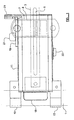
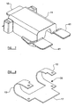
- Figures 1 to 4 show a locking arrangement for a door which, as shown only in Figures 1 and 3 and in dashed lines, is adapted for use with a conventional fastening mechanism.
- the conventional locking mechanism includes an upright operating bar 1 having a handle 3 pivotable mounted thereon.
- the handle includes a forwardly extending flange 5 so as to form a substantially T-shaped cross-section.
- the lower portion of the handle is received in a recess formed in a retainer 7, while a swivel catch 8 is pivotably secured to the retainer and swivels downwardly in use to cover the upper portion of the handle 3 and the top and outer edge of the flange 5.
- the swivel catch 8 and the flange 5 of the handle are formed with co-operating apertures 9 for receiving in normal use a releasable locking mechanism in the form, for example, of the hasp of a padlock or a TIR seal which is conventionally removed for example with bolt cutters. Further details of such a fastening mechanism are shown, for example, in GB-A-2314585 .
- the locking arrangement comprises a housing 11 which is generally in the form of a hollow rectangular box which is open at one face which is adapted to be positioned against the face of the door (not shown). An end face of the housing 11 may also be open in the region of the operating bar 1.
- That end of the housing in the region of the operating bar is optionally provided with two U-shaped members 13 which extend around the operating bar 1 such that the housing is pivotably mounted on the operating bar 1. If desired, however, the U-shaped members may be omitted or the housing 11 could extend beyond the operating bar so that the operating bar passes through the housing, the housing being pivotably mounted on the face of the door at a convenient point beyond the operating bar.
- the forward face of the housing 11 is provided with a protective plate 15 which as illustrated extends between the U-shaped members 13 and at least partly across the operating bar 1 to prevent any interference where the handle 3 is pivotably mounted on the operating bar 1.
- a protective plate 15 which as illustrated extends between the U-shaped members 13 and at least partly across the operating bar 1 to prevent any interference where the handle 3 is pivotably mounted on the operating bar 1.
- a shaped retaining member 17 may be positioned within the U-shaped member 13 so as to provide a reinforcing component which extends behind the operating bar 1 and acts in the manner of a jaw such that, if a thief should seek to cut through the front face of the U-shaped members 13, the shaped retaining member 17 is more difficult to gain access to than is the front face and is more difficult to cut than is the front face of the U-shaped members 13.
- the shape of the retaining member 17 may be triangular, for example, when viewed from above.
- the end of the housing 11 remote from the operating bar 1 covers the retainer 7, while allowing the free end of the handle 3 to protrude from the wall at the free end of the housing 11.
- Slidably mounted in the upper wall of the housing 11 is a closure device.
- the closure device comprises an L-shaped plate 19 positioned externally of the upper wall of the housing 11 with a leg of the plate extending upwardly and adjacent to a complementary plate 21 from the end of the housing 11. Both the closure plate and the complementary plate are provided with corresponding apertures to receive, for example, the hasp of a padlock or a TIR seal.
- the closure plate 21 is movable towards and away from the upper wall of the housing 11 by means of a pin 23 which extends through an aperture provided in the upper wall and through apertures formed in two spaced supporting plates 25 within the housing.
- An upstanding tab 27 is formed on the closure plate 19 to assist moving the plate 19 relative to the housing 11.
- the pin 23 passes in use through the aperture 9 formed in the forwardly extending flange 5 of the handle 3 so as to secure the handle within the housing in a secure manner which also facilitates ready visual confirmation.
- a further pin 29 extends from the closure plate and through the upper wall of the housing 11, the further pin 29 being spaced from the locking pin 23.
- the lower end of the pin 29 is formed with an annular groove into which is fitted an O-ring 31 or the like which is too large to pass through the aperture in the upper wall of the housing and therefore prevents the closure plate 19 from being separated from the housing.
- the further pin 29 is advantageously positioned further to the front wall of the housing 11 than the locking pin 23 to facilitate the passage of the handle 3 through the housing.
- the upper and lower walls of the housing are formed with recesses in the region of the end of the housing remote from the operating bar 1 in order to accommodate the retainer 7 for the door.
- GSM and/or GPS systems may be incorporated into the housing 11.
- the housing may incorporate a key-operated lock 33 or other similar lock which is linked to a sliding arm 35 within the lower region or the housing 11 for engaging with a recess formed in the lower region of the locking pin 23.
- the sliding arm When engaged, the sliding arm prevents the closure plate 19 being lifted away from the upper wall of the housing 11.
- the sliding arm 35 may slide between a lower one of the supporting plates and one or more supports 37 extending upwardly from the lower wall of the housing 11.
- the lock 33 may be employed as an alternative to the apertures in the closure plate 19 and the corresponding plate 21 or may provides a further level of security for the lock arrangement according to the present invention.
- the door is locked by first closing the door, pivoting the handle 3 downwardly to engage with the recess formed in the retainer 7, and then lowering the swivel catch 8 to engage around the upper region of the handle.
- the housing 11 is then pivoted towards the door face and the closure plate 19 is lifted to enable the locking pin 23 to pass over the handle 3 and part of the retainer 7.
- the closure plate, and therefore the locking pin is then lowered such that the locking pin 23 passes through the apertures formed in the swivel catch 8 and the flange of the handle 3 so as to ensure the handle cannot be moved until the housing has been opened.
- the hasp of a padlock, or a TIR seal is then passed through the corresponding apertures formed in the plates 19 and 21 and/or the lock 33 may be secured.
- Opening of the door is effectively the reverse of the locking procedure and the only component that is destroyed is the TIR or like seal if used.
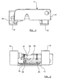
- the locking arrangement shown in Figures 6 to 8 is a modification of that shown in Figures 1 to 4 and the same references are use to denote the same or similar parts.
- the locking arrangement of Figures 6 to 8 differs from that of Figures 1 to 4 in the manner in which the housing 11 is locked.
- Figure 6 shows a conventional locking mechanism which includes an upright operating bar 1 having a handle 3 pivotable mounted thereon.
- the handle includes a forwardly extending flange 5 so as to form a substantially T-shaped cross-section.
- the lower portion of the handle is received in a recess formed in a retainer 7, while a swivel catch 8 is pivotably secured to the retainer and swivels downwardly in use to cover the upper portion of the handle 3 and the top and outer edge of the flange 5.
- the swivel catch 8 and the flange 5 of the handle are formed with co-operating apertures 9 for receiving in normal use the hasp of a padlock or a TIR seal 37.
- the locking arrangement comprises a housing 11 which is generally in the form of a hollow rectangular box which is open at one face which is adapted to be positioned against the face of the door (not shown). An end face of the housing 11 may also be open in the region of the operating bar 1.
- a securing member 39 Secured to that end of the housing in the region of the operating bar is a securing member 39 provided with two U-shaped members 13 which extend around the operating bar 1 such that the housing is pivotably mounted on the operating bar 1. If desired, however, the U-shaped members may be omitted or the housing 11 could extend beyond the operating bar so that the operating bar passes through the housing, the housing being pivotably mounted on the face of the door at a convenient point beyond the operating bar.
- the forward face of the housing 11 is provided with a protective plate 15 which as illustrated extends between the U-shaped members 13 and at least partly across the operating bar 1 to prevent any interference where the handle 3 is pivotably mounted on the operating bar 1.
- a protective plate 15 which as illustrated extends between the U-shaped members 13 and at least partly across the operating bar 1 to prevent any interference where the handle 3 is pivotably mounted on the operating bar 1.
- a shaped retaining member 17 may provide a reinforcing component which extends behind the operating bar 1 and acts in the manner of a jaw such that, if a thief should seek to cut through the front face of the U-shaped members 13, the shaped retaining member 17 is more difficult to gain access to than is the front face and is more difficult to cut than is the front face of the U-shaped members 13.
- the end of the housing 11 remote from the operating bar 1 terminates short of the retainer 7, but is provided with two plates 41 which extend in spaced-apart manner along the upper and lower sides of the handle 3 so as to cover the retainer 7 and the swivel catch 8 while allowing access to the openings 9 so as to permit a TIR seal 37 or the like to be passed through the openings with the seal bearing against the outer faces of the plates 41.
- the TIR seal 37 or the like prevents the housing 11 being moved, while the plates 41 prevent access to the swivel catch 8 and retainer 7.
- GSM and/or GPS systems may be incorporated into the housing 11.
Landscapes
- Lock And Its Accessories (AREA)
Claims (15)
- Un dispositif de verrouillage pour une porte, le dispositif de verrouillage comprenant une barre d'actionnement verticale (1) montée sur la porte pour un déplacement angulaire autour de son axe et une poignée (3) qui est raccordée à la barre d'actionnement par un raccord pivotant pour entrer en prise avec un mécanisme de fermeture (7, 8), la poignée et le mécanisme de fermeture comprenant des ouvertures associées (9), caractérisé en ce que le dispositif de verrouillage comprend en outre :un boîtier (11) adapté de façon à couvrir le raccord pivotant de la poignée et au moins une partie du mécanisme de fermeture,un moyen de fixation libérable (35) passant par des ouvertures formées dans à la fois la poignée et le mécanisme de fermeture et fixant le boîtier à la poignée et au mécanisme de fermeture.
- Un dispositif de verrouillage selon la Revendication 1, caractérisé en ce que le boîtier (11) est monté pivotant sur la barre d'actionnement (1).
- Un dispositif de verrouillage selon la Revendication 1, caractérisé en ce que le boîtier (11) est monté pivotant sur la porte.
- Un dispositif de verrouillage selon la Revendication 2 ou 3, caractérisé en ce que le boîtier (11) ou un ou plusieurs éléments en forme de U (13) montant le boîtier (11) sur la barre d'actionnement (1) sont équipés d'un élément de retenue (17) qui est adapté de façon à être positionné derrière la barre d'actionnement (1).
- Un dispositif de verrouillage selon l'une quelconque des Revendications précédentes, caractérisé en ce que le boîtier (11) est équipé d'une plaque de protection (15) qui s'étend au moins partiellement d'un côté à l'autre de la barre d'actionnement (1).
- Un dispositif de verrouillage selon l'une quelconque des Revendications précédentes, caractérisé en ce que le boîtier (11) englobe sensiblement à la fois le raccord pivotant de la poignée (3) et le mécanisme de fermeture (7, 8).
- Un dispositif de verrouillage selon la Revendication 6, caractérisé en ce que le moyen de fixation libérable comprend un élément de verrouillage (23) monté de manière coulissante dans le boîtier (11) entre une première position dans laquelle la poignée (3) est déplaçable par rapport au mécanisme de fermeture (7, 8) et une deuxième position dans laquelle l'élément de verrouillage passe au travers des ouvertures (9) formées dans la poignée et le mécanisme de fermeture.
- Un dispositif de verrouillage selon la Revendication 7, caractérisé en ce que le moyen de fixation libérable comprend en outre un moyen pour fixer de manière libérable l'élément de verrouillage (23) par rapport au boîtier (11) de façon à empêcher l'élément de verrouillage d'être déplacé de la deuxième position vers la première position.
- Un dispositif de verrouillage selon la Revendication 7 ou 8, caractérisé en ce que l'élément de verrouillage (23) comprend une goupille passant par les ouvertures (9) dans la poignée (3) et le mécanisme de fermeture (7, 8), la goupille passant en outre par une ouverture formée dans le boîtier (11).
- Un dispositif de verrouillage selon la Revendication 9, caractérisé en ce que l'élément de verrouillage (23) comprend une plaque (19) fixée sur une zone d'extrémité de la goupille de façon externe au boîtier (11).
- Un dispositif de verrouillage selon la Revendication 10, caractérisé en ce qu'une autre goupille (29) est fixée sur la plaque (19) espacée de la goupille de verrouillage (23) et s'étend dans le boîtier (11) par une ouverture formée dans celui-ci de façon à maintenir l'alignement de la plaque (19).
- Un dispositif de verrouillage selon la Revendication 11, caractérisé en ce que l'extrémité inférieure de l'autre goupille (29) est équipée d'un moyen (31) destiné à empêcher le retrait de l'élément de verrouillage (23) du boîtier (11).
- Un dispositif de verrouillage selon l'une quelconque des Revendications 10 à 12, caractérisé en ce que la plaque (19) formant une partie de l'élément de verrouillage (23) est formée d'une ouverture qui s'aligne avec une ouverture formée dans le boîtier (11) de façon à recevoir le moyen de fixation libérable (35).
- Un dispositif de verrouillage selon l'une quelconque des Revendications 7 à 13, caractérisé en ce que le moyen de fixation libérable comprend un verrou (33) adapté de façon à déplacer un élément coulissant (35) en prise avec l'élément de verrouillage (23).
- Un dispositif de verrouillage selon l'une quelconque des Revendications 1 à 5, caractérisé en ce que le boîtier (11) contient le raccord pivotant de la poignée (3) et comprend un élément de type plaque (41) couvrant au moins une partie du mécanisme de fermeture (7, 8), le moyen de fixation libérable s'appuyant contre l'élément de type plaque de façon à fixer le boîtier à la poignée et au mécanisme de fermeture.
Applications Claiming Priority (2)
| Application Number | Priority Date | Filing Date | Title |
|---|---|---|---|
| GB0615853A GB0615853D0 (en) | 2006-08-10 | 2006-08-10 | Locking arrangement for a door |
| PCT/GB2007/003019 WO2008017841A1 (fr) | 2006-08-10 | 2007-08-08 | Mécanisme de verrouillage pour porte |
Publications (2)
| Publication Number | Publication Date |
|---|---|
| EP2054569A1 EP2054569A1 (fr) | 2009-05-06 |
| EP2054569B1 true EP2054569B1 (fr) | 2010-02-17 |
Family
ID=37056101
Family Applications (1)
| Application Number | Title | Priority Date | Filing Date |
|---|---|---|---|
| EP20070789153 Expired - Fee Related EP2054569B1 (fr) | 2006-08-10 | 2007-08-08 | Mécanisme de verrouillage pour porte |
Country Status (7)
| Country | Link |
|---|---|
| US (1) | US8353543B2 (fr) |
| EP (1) | EP2054569B1 (fr) |
| CN (1) | CN101517179B (fr) |
| DE (1) | DE602007004862D1 (fr) |
| ES (1) | ES2341382T3 (fr) |
| GB (1) | GB0615853D0 (fr) |
| WO (1) | WO2008017841A1 (fr) |
Families Citing this family (6)
| Publication number | Priority date | Publication date | Assignee | Title |
|---|---|---|---|---|
| DE102009056921A1 (de) * | 2009-12-03 | 2011-06-09 | GM Global Technology Operations LLC, ( n. d. Ges. d. Staates Delaware ), Detroit | Griffmodul für eine Kraftfahrzeugtür |
| GB201218647D0 (en) | 2012-10-17 | 2012-11-28 | Guardfreight Internat Ltd | Security devices |
| US10557532B2 (en) | 2015-05-22 | 2020-02-11 | Hubert Junior Hill | Movable latch housing apparatus |
| US10655365B2 (en) * | 2017-06-23 | 2020-05-19 | Fenix Manufacturing Co., Llc | Gate latch assembly |
| CN107780731A (zh) * | 2017-11-27 | 2018-03-09 | 江苏神山风电设备制造有限公司 | 一种风电塔筒门锁装置及其工作方法 |
| US11913261B2 (en) * | 2019-02-01 | 2024-02-27 | Nissan North America, Inc. | Vehicle door assembly and mounting structure for a door handle |
Family Cites Families (43)
| Publication number | Priority date | Publication date | Assignee | Title |
|---|---|---|---|---|
| US2374585A (en) | 1944-03-11 | 1945-04-24 | Conlan Electric Corp | Door switch |
| US2997752A (en) * | 1957-03-27 | 1961-08-29 | Pacific Car & Foundry Co | Railway car door and mechanism therefor |
| US3217661A (en) * | 1963-12-02 | 1965-11-16 | Acf Ind Inc | Hatch cover structure |
| US3312493A (en) * | 1965-08-02 | 1967-04-04 | Miner Inc W H | Door fastener |
| US3415085A (en) * | 1966-06-01 | 1968-12-10 | George Eble Jr. | Lock for truck trailer |
| US3484127A (en) * | 1966-07-11 | 1969-12-16 | Eastern Co | Door securing apparatus |
| US3451705A (en) * | 1966-10-06 | 1969-06-24 | Compass Container Co Inc | Cargo container door latching arrangement |
| DE1960697C3 (de) * | 1969-12-03 | 1979-04-19 | F. Hesterberg & Soehne, 5828 Ennepetal | Drehstangenverschluß für Transportbehälter |
| US3606423A (en) * | 1969-12-19 | 1971-09-20 | Ridgewood Instr Co | Lock protecting assembly |
| GB2062084A (en) | 1979-10-29 | 1981-05-20 | Zivanovic M | A Device to Prevent Unauthorised Opening of a Door Having an Espagnolette Closure Such as the Door of a Lorry |
| US4581907A (en) * | 1984-01-30 | 1986-04-15 | Eberly David S | Padlock protector |
| US5024473A (en) * | 1989-02-13 | 1991-06-18 | Mcquade Donald E | Gate locking device featuring dead bolt means |
| US5103658A (en) * | 1991-01-28 | 1992-04-14 | Mcquade Donald E | Self locking gate latch |
| US5154458A (en) * | 1992-02-28 | 1992-10-13 | International Trade & Technologies, Inc. | Security device for cargo doors and similar articles |
| JP2724297B2 (ja) * | 1995-11-29 | 1998-03-09 | ビクター ナァバァルスキー | コンテナ用ドア閉鎖ロッドの施錠装置 |
| GB9613442D0 (en) | 1996-06-26 | 1996-08-28 | Bloxwich Eng | Improvements in fastening mechanisms for doors |
| US5737946A (en) * | 1996-09-30 | 1998-04-14 | Sole; Jeffrey S. | Semi-trailer anti-theft device |
| AU729899B2 (en) * | 1997-06-09 | 2001-02-15 | Henning Kummerfeldt | A locking device |
| GB2330377A (en) | 1997-09-03 | 1999-04-21 | Bloxwich Transport Prod Ltd | Tamper indicative fastener for trailer door |
| US6609739B1 (en) * | 1998-08-04 | 2003-08-26 | Meir Avganim | Locking devices for gates and the like |
| US6010166A (en) * | 1998-08-24 | 2000-01-04 | Transguard Industries, Inc. | Bolt seal protector hasp |
| US6553798B1 (en) * | 1999-09-22 | 2003-04-29 | Allan R Larsen | Door block for container |
| US6357266B1 (en) * | 2000-06-01 | 2002-03-19 | Randy C. Van Buren | Latch cover |
| US6846024B1 (en) * | 2001-03-30 | 2005-01-25 | Gabriel Technologies Corp. | Security cover system for cargo container latch |
| US6519982B1 (en) * | 2001-10-05 | 2003-02-18 | Trans-Guard Industries, Inc. | Bolt seal protector |
| DK176084B1 (da) * | 2001-12-10 | 2006-04-24 | Servial Cc Aps | Låsearrangement til en dör |
| US6601413B1 (en) * | 2002-01-24 | 2003-08-05 | Robert A. Vito | Hasp enclosure for receiving a lock |
| US6581419B1 (en) * | 2002-03-07 | 2003-06-24 | Forrest E. Strodtman | Hasp and lock cover for cargo doors |
| CN2561891Y (zh) * | 2002-07-18 | 2003-07-23 | 上田华子 | 货车把手的锁具控制装置 |
| US20040221626A1 (en) * | 2002-08-28 | 2004-11-11 | Palzkill Raymond G. | Security cover with releasable lock |
| US7063362B1 (en) * | 2002-11-25 | 2006-06-20 | Jeffrey Howard Liroff | Seal assembly for a cargo container |
| GB2389142B (en) * | 2003-02-21 | 2004-04-14 | David Carter | Security device, use of a security device and a method of securing a handle |
| GB0312023D0 (en) * | 2003-05-24 | 2003-07-02 | Reynard Kenneth | Container hinge with customs seal provision |
| US6823701B1 (en) * | 2003-08-29 | 2004-11-30 | Roy E. Gogel | Door latching device |
| US7272963B2 (en) * | 2003-09-11 | 2007-09-25 | Cargo Protectors, Inc. | Gate latch |
| US6928843B1 (en) * | 2003-10-17 | 2005-08-16 | James T. Pirnie | Seal enclosure assembly for cargo doors |
| US20050144991A1 (en) * | 2004-01-06 | 2005-07-07 | Bravo Ramiro H. | Reusable hasp-locking mechanism |
| US20060201210A1 (en) * | 2004-09-23 | 2006-09-14 | Gogel Roy E | Stanchion lever lock guard |
| US7210316B1 (en) * | 2006-02-14 | 2007-05-01 | Blaylock Industries, Inc. | Door lock for trailers and cargo containers |
| US7278284B1 (en) * | 2006-09-20 | 2007-10-09 | James Robert L | Lock box for sealed latch assembly |
| US7441425B2 (en) * | 2006-09-28 | 2008-10-28 | Kum-Sik Jeong | Door lock of cargo container having burglarproof function |
| US7412856B1 (en) * | 2006-11-01 | 2008-08-19 | Gogel Roy E | Lock guard for long shackle padlock over handle |
| US7921685B2 (en) * | 2009-07-28 | 2011-04-12 | Ryadon, Inc. | Latch assembly with security bracket |
-
2006
- 2006-08-10 GB GB0615853A patent/GB0615853D0/en not_active Ceased
-
2007
- 2007-08-08 DE DE200760004862 patent/DE602007004862D1/de active Active
- 2007-08-08 EP EP20070789153 patent/EP2054569B1/fr not_active Expired - Fee Related
- 2007-08-08 ES ES07789153T patent/ES2341382T3/es active Active
- 2007-08-08 US US12/376,505 patent/US8353543B2/en not_active Expired - Fee Related
- 2007-08-08 WO PCT/GB2007/003019 patent/WO2008017841A1/fr active Application Filing
- 2007-08-08 CN CN2007800352719A patent/CN101517179B/zh not_active Expired - Fee Related
Also Published As
| Publication number | Publication date |
|---|---|
| CN101517179A (zh) | 2009-08-26 |
| DE602007004862D1 (de) | 2010-04-01 |
| US20100181782A1 (en) | 2010-07-22 |
| GB0615853D0 (en) | 2006-09-20 |
| CN101517179B (zh) | 2013-11-13 |
| ES2341382T3 (es) | 2010-06-18 |
| US8353543B2 (en) | 2013-01-15 |
| WO2008017841A1 (fr) | 2008-02-14 |
| EP2054569A1 (fr) | 2009-05-06 |
Similar Documents
| Publication | Publication Date | Title |
|---|---|---|
| US6581419B1 (en) | Hasp and lock cover for cargo doors | |
| US6708532B2 (en) | Hinged security cover for vehicle door hasp | |
| US6357266B1 (en) | Latch cover | |
| US5284036A (en) | Tamper-resistant security lock for cargo container doors | |
| US4581907A (en) | Padlock protector | |
| EP2054569B1 (fr) | Mécanisme de verrouillage pour porte | |
| US6058745A (en) | Cover for padlocks | |
| US6935660B1 (en) | Premium door locking system | |
| US7201028B1 (en) | Stanchion lever lock guard | |
| US6233984B1 (en) | Semitrailer cargo, door locking system | |
| US7874188B2 (en) | Anti-theft latch shield | |
| US4566296A (en) | Padlock security cover | |
| US5791702A (en) | Tamper evident, cargo container door lock | |
| NZ554809A (en) | Dual locking system for containers | |
| US5154458A (en) | Security device for cargo doors and similar articles | |
| US20040221626A1 (en) | Security cover with releasable lock | |
| CA2988887C (fr) | Appareil et methode de fixation de portes de wagon | |
| US5303971A (en) | Tailgate release handle security device | |
| US20120103032A1 (en) | Security cover for cargo containers | |
| US20060201211A1 (en) | Lock guard with protective roof | |
| US8266932B2 (en) | Theft deterrent locking hasp | |
| EP2096048A1 (fr) | Dispositif de barre à verrou anti-vol pour conteneur | |
| US10871012B2 (en) | End door latch arrangement for railroad car | |
| US11346135B1 (en) | Cover assembly for lock assembly of a shipping container | |
| US20050126235A1 (en) | Method and kit for securing an upwardly acting cargo container door |
Legal Events
| Date | Code | Title | Description |
|---|---|---|---|
| PUAI | Public reference made under article 153(3) epc to a published international application that has entered the european phase |
Free format text: ORIGINAL CODE: 0009012 |
|
| 17P | Request for examination filed |
Effective date: 20090227 |
|
| AK | Designated contracting states |
Kind code of ref document: A1 Designated state(s): AT BE BG CH CY CZ DE DK EE ES FI FR GB GR HU IE IS IT LI LT LU LV MC MT NL PL PT RO SE SI SK TR |
|
| AX | Request for extension of the european patent |
Extension state: AL BA HR MK RS |
|
| GRAP | Despatch of communication of intention to grant a patent |
Free format text: ORIGINAL CODE: EPIDOSNIGR1 |
|
| DAX | Request for extension of the european patent (deleted) | ||
| RBV | Designated contracting states (corrected) |
Designated state(s): DE ES FR GB NL |
|
| GRAS | Grant fee paid |
Free format text: ORIGINAL CODE: EPIDOSNIGR3 |
|
| GRAA | (expected) grant |
Free format text: ORIGINAL CODE: 0009210 |
|
| AK | Designated contracting states |
Kind code of ref document: B1 Designated state(s): DE ES FR GB NL |
|
| REG | Reference to a national code |
Ref country code: GB Ref legal event code: FG4D |
|
| REF | Corresponds to: |
Ref document number: 602007004862 Country of ref document: DE Date of ref document: 20100401 Kind code of ref document: P |
|
| REG | Reference to a national code |
Ref country code: NL Ref legal event code: T3 |
|
| REG | Reference to a national code |
Ref country code: ES Ref legal event code: FG2A Ref document number: 2341382 Country of ref document: ES Kind code of ref document: T3 |
|
| PLBE | No opposition filed within time limit |
Free format text: ORIGINAL CODE: 0009261 |
|
| STAA | Information on the status of an ep patent application or granted ep patent |
Free format text: STATUS: NO OPPOSITION FILED WITHIN TIME LIMIT |
|
| 26N | No opposition filed |
Effective date: 20101118 |
|
| PGFP | Annual fee paid to national office [announced via postgrant information from national office to epo] |
Ref country code: ES Payment date: 20110915 Year of fee payment: 5 |
|
| PGFP | Annual fee paid to national office [announced via postgrant information from national office to epo] |
Ref country code: FR Payment date: 20130319 Year of fee payment: 6 |
|
| REG | Reference to a national code |
Ref country code: ES Ref legal event code: FD2A Effective date: 20131018 |
|
| PG25 | Lapsed in a contracting state [announced via postgrant information from national office to epo] |
Ref country code: ES Free format text: LAPSE BECAUSE OF NON-PAYMENT OF DUE FEES Effective date: 20120809 |
|
| REG | Reference to a national code |
Ref country code: FR Ref legal event code: ST Effective date: 20140430 |
|
| PG25 | Lapsed in a contracting state [announced via postgrant information from national office to epo] |
Ref country code: FR Free format text: LAPSE BECAUSE OF NON-PAYMENT OF DUE FEES Effective date: 20130902 |
|
| PGFP | Annual fee paid to national office [announced via postgrant information from national office to epo] |
Ref country code: DE Payment date: 20140821 Year of fee payment: 8 Ref country code: NL Payment date: 20140823 Year of fee payment: 8 |
|
| REG | Reference to a national code |
Ref country code: DE Ref legal event code: R119 Ref document number: 602007004862 Country of ref document: DE |
|
| REG | Reference to a national code |
Ref country code: NL Ref legal event code: MM Effective date: 20150901 |
|
| PGFP | Annual fee paid to national office [announced via postgrant information from national office to epo] |
Ref country code: GB Payment date: 20160203 Year of fee payment: 9 |
|
| PG25 | Lapsed in a contracting state [announced via postgrant information from national office to epo] |
Ref country code: NL Free format text: LAPSE BECAUSE OF NON-PAYMENT OF DUE FEES Effective date: 20150901 |
|
| PG25 | Lapsed in a contracting state [announced via postgrant information from national office to epo] |
Ref country code: DE Free format text: LAPSE BECAUSE OF NON-PAYMENT OF DUE FEES Effective date: 20160301 |
|
| GBPC | Gb: european patent ceased through non-payment of renewal fee |
Effective date: 20160808 |
|
| PG25 | Lapsed in a contracting state [announced via postgrant information from national office to epo] |
Ref country code: GB Free format text: LAPSE BECAUSE OF NON-PAYMENT OF DUE FEES Effective date: 20160808 |