EP2053878A2 - Hearing aid using an inductive switching regulator as a radio transmitter - Google Patents
Hearing aid using an inductive switching regulator as a radio transmitter Download PDFInfo
- Publication number
- EP2053878A2 EP2053878A2 EP08164390A EP08164390A EP2053878A2 EP 2053878 A2 EP2053878 A2 EP 2053878A2 EP 08164390 A EP08164390 A EP 08164390A EP 08164390 A EP08164390 A EP 08164390A EP 2053878 A2 EP2053878 A2 EP 2053878A2
- Authority
- EP
- European Patent Office
- Prior art keywords
- switching regulator
- inductance
- hearing
- transmitting device
- modulation
- Prior art date
- Legal status (The legal status is an assumption and is not a legal conclusion. Google has not performed a legal analysis and makes no representation as to the accuracy of the status listed.)
- Granted
Links
Images

Classifications
-
- H—ELECTRICITY
- H04—ELECTRIC COMMUNICATION TECHNIQUE
- H04R—LOUDSPEAKERS, MICROPHONES, GRAMOPHONE PICK-UPS OR LIKE ACOUSTIC ELECTROMECHANICAL TRANSDUCERS; DEAF-AID SETS; PUBLIC ADDRESS SYSTEMS
- H04R25/00—Deaf-aid sets, i.e. electro-acoustic or electro-mechanical hearing aids; Electric tinnitus maskers providing an auditory perception
- H04R25/55—Deaf-aid sets, i.e. electro-acoustic or electro-mechanical hearing aids; Electric tinnitus maskers providing an auditory perception using an external connection, either wireless or wired
- H04R25/554—Deaf-aid sets, i.e. electro-acoustic or electro-mechanical hearing aids; Electric tinnitus maskers providing an auditory perception using an external connection, either wireless or wired using a wireless connection, e.g. between microphone and amplifier or using Tcoils
-
- H—ELECTRICITY
- H04—ELECTRIC COMMUNICATION TECHNIQUE
- H04R—LOUDSPEAKERS, MICROPHONES, GRAMOPHONE PICK-UPS OR LIKE ACOUSTIC ELECTROMECHANICAL TRANSDUCERS; DEAF-AID SETS; PUBLIC ADDRESS SYSTEMS
- H04R2225/00—Details of deaf aids covered by H04R25/00, not provided for in any of its subgroups
- H04R2225/61—Aspects relating to mechanical or electronic switches or control elements, e.g. functioning
-
- H—ELECTRICITY
- H04—ELECTRIC COMMUNICATION TECHNIQUE
- H04R—LOUDSPEAKERS, MICROPHONES, GRAMOPHONE PICK-UPS OR LIKE ACOUSTIC ELECTROMECHANICAL TRANSDUCERS; DEAF-AID SETS; PUBLIC ADDRESS SYSTEMS
- H04R25/00—Deaf-aid sets, i.e. electro-acoustic or electro-mechanical hearing aids; Electric tinnitus maskers providing an auditory perception
- H04R25/35—Deaf-aid sets, i.e. electro-acoustic or electro-mechanical hearing aids; Electric tinnitus maskers providing an auditory perception using translation techniques
- H04R25/353—Frequency, e.g. frequency shift or compression
Definitions
- the present invention relates to a hearing apparatus with a switching regulator including an inductor and a transmitter including an antenna for wireless electromagnetic transmission of data.
- a hearing device is understood here to mean any device for sound output which can be worn on or in the ear, in particular a hearing device, a headset, headphones and the like.
- Hearing aids are portable hearing aids that are used to care for the hearing impaired.
- different types of hearing aids such as behind-the-ear hearing aids (BTE), hearing aid with external receiver (RIC: receiver in the canal) and in-the-ear hearing aids (IDO), e.g. Concha hearing aids or canal hearing aids (ITE, CIC).
- BTE behind-the-ear hearing aids
- RIC hearing aid with external receiver
- IDO in-the-ear hearing aids
- ITE canal hearing aids
- the hearing aids listed by way of example are worn on the outer ear or in the ear canal.
- bone conduction hearing aids, implantable or vibrotactile hearing aids are also available on the market. The stimulation of the damaged hearing takes place either mechanically or electrically.
- Hearing aids have in principle as essential components an input transducer, an amplifier and an output transducer.
- the input transducer is usually a sound receiver, z. As a microphone, and / or an electromagnetic receiver, for. B. an induction coil.
- the output transducer is usually used as an electroacoustic transducer, z. As miniature speaker, or as an electromechanical transducer, z. B. bone conduction, realized.
- the amplifier is usually integrated in a signal processing unit. This basic structure is in FIG. 1 shown using the example of a behind-the-ear hearing aid. In a hearing aid housing 1 for carrying behind the ear are one or more microphones 2 to Built-in sound recording from the environment.
- a signal processing unit 3 which is also integrated in the hearing aid housing 1, processes the microphone signals and amplifies them.
- the output signal of the signal processing unit 3 is transmitted to a loudspeaker or earpiece 4, which outputs an acoustic signal.
- the sound is optionally transmitted via a sound tube, which is fixed with an earmold in the ear canal, to the eardrum of the device carrier.
- the power supply of the hearing device and in particular of the signal processing unit 3 is carried out by a likewise integrated into the hearing aid housing 1 battery. 5
- the cell voltage which is higher than, for example, alkaline-manganese batteries or zinc-air batteries, must be reduced if the technology designed for 1.5 volt cells continues to be used should.
- This technology which is currently in use, is designed for voltages below 1.5 volts to save energy.
- lithium batteries deliver 3.0 volts and lithium batteries even nominally 3.6 volts to a maximum of 4.2 volts.
- the object of the present invention is therefore to reduce the size of a hearing device having a transmitting device and a power supply with voltage regulation.
- this object is achieved by a hearing device with a transmitting device including an antenna for wireless, electromagnetic transmission of data, and a switching regulator including an inductor, which serves for the power supply of the hearing device and the transmitting device, wherein the inductance of the switching regulator with the antenna of the transmitting device is identical.
- the inductance may comprise a partially open ring core. Due to the fact that the toroidal core is not completely closed, the magnetic flux is not completely guided in the toroidal core and can be used for electromagnetic data transmission.
- an alternative embodiment is that the inductance in a cross-section 8-shaped, on one or has two sides open core.
- the one or more openings serve to selectively effect electromagnetic emissions in order to realize a data transmission.
- pulse width modulation pulse density modulation or amplitude modulation is used in the switching regulator for energy transmission.
- modulation are characterized by the fact that they, as mentioned above, hardly affect the fundamental frequency and the fundamental phase of the signal of the switching regulator.
- a further advantageous embodiment is that an additional inductance with a closed core is connected to the inductance switchable.
- the additional inductance of the magnetic circuit is thus closed in the core, so that electromagnetic emissions are avoided as much as possible.
- the hearing device here a hearing aid, an input transducer, in this case a microphone 10.
- the microphone signal is fed to a signal processing unit 11, which in turn transmits an output signal to a receiver or loudspeaker 12.
- the signal processing device 11 has a battery 13 with a downstream switching regulator 14.
- the switching regulator 14 transforms the voltage supplied by the battery 13 to the desired operating voltage. If, for example, a lithium battery with 3 volts is used, the voltage is reduced below 1.5 volts, for example, with the aid of the switching regulator 14.
- a rechargeable battery such as a lithium battery with nominally about 3.8 volts.
- the voltage regulator 14 then regulates the battery voltage from 3.8 volts to, for example, 1.2 volts operating voltage.
- the switching regulator 14 is an inductive switching regulator which has an inductance 15 for regulating the voltage.
- the inductance is used to smooth the output voltage during switching operations.
- FIG. 2 Furthermore, the hearing of FIG. 2 via a transmitter 16, which uses the inductance 15 as an antenna.
- the inductance 15 is thus both part of the switching regulator 14 and the transmitter 16, which in FIG. 2 is indicated by the dashed line.
- the inductor 15 thus has dual functionality.
- the transmitter 16 is supplied as the signal processing unit 11 via the switching regulator 14 with energy.
- the data to be transmitted is received by the transmitter 16 from the signal processing unit 11.
- a single inductor 15 is used simultaneously for the switching regulator 14 and the transmitter 16, whereby a total of an inductance, which is known to require a lot of space, can be saved. So that the inductance can also be used as a transmitter or transmitting antenna, it must be able to radiate at least part of the magnetic energy. This can be achieved for example by an inductor z. B. does not have a closed ring core, but has a more or less large air gap in the ring.
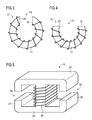
- FIG. 3 A first exemplary embodiment of such an inductor used according to the invention is shown in FIG FIG. 3 reproduced in plan view.
- the inductor 15 here has a ring core 17 with a small gap 18.
- the end faces 19, 20 of the gap 18 face each other, so that the magnetic field lines only slightly out of the gap. Consequently, only a weakly radiating antenna can be realized with this toroidal geometry.
- FIG. 4 An example of this is in FIG. 4 shown. Again, it is an inductance 15 with a ring core 17.
- the ring core 17 here has a large gap 21, wherein the end faces 22, 23 of the open ring core 17 are not directed towards each other. This geometry results in a completely different emission characteristic than in the example of FIG. 3 , In particular, the magnetic field lines extend far out of the gap 21, resulting in a stronger radiation.
- any inductance whose core does not form a closed magnetic circuit If the core is closed, as mentioned, only a negligible proportion of the magnetic flux is conducted outside the core, which is unsuitable for an electromagnetic transmitter.
- the geometry of the core of the inductance 15 is therefore to be optimized with regard to the emission characteristic, wherein a compromise is to be found with respect to as little energy loss as possible for the function of the switching regulator. For example, a linear dipole would be optimal for the transmitter, but unsuitable for the switching regulator, because it radiates almost all of the energy.
- FIG. 5 A third embodiment of an inductor for common use for a switching regulator 14 and a transmitter 16 is shown in FIG FIG. 5 shown.
- the core 24 has here in cross-section substantially the shape of an "8".
- a winding 26 is wound.
- the central web 25 is closed, while the two outer webs 27 and 28 each have a gap 29 and 30, respectively. These two gaps 29, 30 again provide the desired electromagnetic radiation.
- the design of the inductor 15 is particularly suitable for SMD components, since they can be realized so very flat.
- the pulse width modulation of the switching regulator can be realized independently of the modulations of the data transmission by means of conventional circuits.
- a changing load of the switching regulator 14 would of course change the transmission energy due to the common use of the inductance 15.
- the transmit power can be tuned to a system and its expected load by matching the radiated power and the shorted power by the geometry of the antenna or inductor, respectively.
Abstract
Description
Die vorliegende Erfindung betrifft eine Hörvorrichtung mit einem Schaltregler einschließlich einer Induktivität und einer Sendeeinrichtung einschließlich einer Antenne zum drahtlosen, elektromagnetischen Senden von Daten. Unter dem Begriff "Hörvorrichtung" wird hier jedes am oder im Ohr tragbare Gerät zur Schallausgabe, insbesondere ein Hörgerät, ein Headset, Kopfhörer und dergleichen verstanden.The present invention relates to a hearing apparatus with a switching regulator including an inductor and a transmitter including an antenna for wireless electromagnetic transmission of data. The term "hearing device" is understood here to mean any device for sound output which can be worn on or in the ear, in particular a hearing device, a headset, headphones and the like.
Hörgeräte sind tragbare Hörvorrichtungen, die zur Versorgung von Schwerhörenden dienen. Um den zahlreichen individuellen Bedürfnissen entgegenzukommen, werden unterschiedliche Bauformen von Hörgeräten wie Hinter-dem-Ohr-Hörgeräte (HdO), Hörgerät mit externem Hörer (RIC: receiver in the canal) und In-dem-Ohr-Hörgeräte (IdO), z.B. auch Concha-Hörgeräte oder Kanal-Hörgeräte (ITE, CIC), bereitgestellt. Die beispielhaft aufgeführten Hörgeräte werden am Außenohr oder im Gehörgang getragen. Darüber hinaus stehen auf dem Markt aber auch Knochenleitungshörhilfen, implantierbare oder vibrotaktile Hörhilfen zur Verfügung. Dabei erfolgt die Stimulation des geschädigten Gehörs entweder mechanisch oder elektrisch.Hearing aids are portable hearing aids that are used to care for the hearing impaired. In order to meet the numerous individual needs, different types of hearing aids such as behind-the-ear hearing aids (BTE), hearing aid with external receiver (RIC: receiver in the canal) and in-the-ear hearing aids (IDO), e.g. Concha hearing aids or canal hearing aids (ITE, CIC). The hearing aids listed by way of example are worn on the outer ear or in the ear canal. In addition, bone conduction hearing aids, implantable or vibrotactile hearing aids are also available on the market. The stimulation of the damaged hearing takes place either mechanically or electrically.
Hörgeräte besitzen prinzipiell als wesentliche Komponenten einen Eingangswandler, einen Verstärker und einen Ausgangswandler. Der Eingangswandler ist in der Regel ein Schallempfänger, z. B. ein Mikrofon, und/oder ein elektromagnetischer Empfänger, z. B. eine Induktionsspule. Der Ausgangswandler ist meist als elektroakustischer Wandler, z. B. Miniaturlautsprecher, oder als elektromechanischer Wandler, z. B. Knochenleitungshörer, realisiert. Der Verstärker ist üblicherweise in eine Signalverarbeitungseinheit integriert. Dieser prinzipielle Aufbau ist in
Sobald in einem Hörgerät eine auf Lithium basierende Technologie als Energiespender verwendet werden soll, muss die im Vergleich beispielsweise zu Alkali-Mangan-Batterien oder Zink-Luft-Batterien höhere Zellenspannung reduziert werden, wenn die für 1,5 Volt-Zellen konzipierte Technologie weiterverwendet werden soll. Diese in der Regel derzeit verwendete Technologie ist aus Energiespargründen auf Spannungen unter 1,5 Volt ausgelegt. Lithium-Batterien liefern jedoch 3,0 Volt und Lithium-Akkus sogar nominal 3,6 Volt bis maximal 4,2 Volt.As soon as a lithium-based technology is to be used as an energy donor in a hearing aid, the cell voltage, which is higher than, for example, alkaline-manganese batteries or zinc-air batteries, must be reduced if the technology designed for 1.5 volt cells continues to be used should. This technology, which is currently in use, is designed for voltages below 1.5 volts to save energy. However, lithium batteries deliver 3.0 volts and lithium batteries even nominally 3.6 volts to a maximum of 4.2 volts.
Eine effiziente Methode, die Zellenspannung auf die gewünschte Betriebsspannung herabzusetzen, ohne dabei größere Mengen an Energie zu verlieren, besteht in dem Einsatz eines Schaltreglers. Moderne Hörsysteme sind außerdem vielfach mit Funksystemen ausgestattet, um Daten drahtlos zu übertragen. Eine Kombination dieser beiden Technologien führt nun zu dem Problem, dass elektromagnetische Verluste des Schaltreglers zu Störungen des Funksystems führen. Insbesondere kommt es zu Störungen im Bereich der Grundfrequenz und allen Vielfachen des Signals des Schaltreglers.An efficient way to reduce the cell voltage to the desired operating voltage without losing large amounts of energy is to use a switching regulator. Modern hearing systems are also often equipped with radio systems to transmit data wirelessly. A combination of these two technologies now leads to the problem that electromagnetic losses of the switching regulator lead to disturbances of the radio system. In particular, there are disturbances in the range of the fundamental frequency and all multiples of the signal of the switching regulator.
Bislang wurden für Hörvorrichtungen kaum Lithium-Energiespender eingesetzt. Daher trat die Problematik der Störungen eines Funksystems durch Schaltregler bei Hörvorrichtungen praktisch nicht auf. Aufgrund von Forderungen nach Akkus werden aber zukünftig immer mehr Lithium-Systeme eingesetzt werden.So far, hardly any lithium energy donors have been used for hearing aids. Therefore, the problem of disturbances of a radio system by switching regulator in hearing devices practically did not occur. Due to demands for Batteries will be used in the future more and more lithium systems.
Generell besteht bei Hörvorrichtungen und insbesondere bei Hörgeräten der Wunsch nach Reduzierung der Baugröße. Hierzu kontraproduktiv ist das Bestreben, möglichst viele Funktionen in einer Hörvorrichtung bereitzustellen bzw. Energiespender einsetzen zu wollen, die eine erhöhte Energieabgabe ermöglicht.In general, there is a desire for hearing devices and hearing aids in particular to reduce the size. Counterproductive is the endeavor to provide as many functions as possible in a hearing device or to use energy donors, which allows an increased energy release.
Die Aufgabe der vorliegenden Erfindung besteht somit darin, die Baugröße einer Hörvorrichtung, die eine Sendeeinrichtung und eine Energieversorgung mit Spannungsregelung aufweist, zu reduzieren.The object of the present invention is therefore to reduce the size of a hearing device having a transmitting device and a power supply with voltage regulation.
Erfindungsgemäß wird diese Aufgabe gelöst durch eine Hörvorrichtung mit einer Sendeeinrichtung einschließlich einer Antenne zum drahtlosen, elektromagnetischen Senden von Daten, und einem Schaltregler einschließlich einer Induktivität, der für die Energieversorgung der Hörvorrichtung und der Sendeeinrichtung dient, wobei die Induktivität des Schaltreglers mit der Antenne der Sendeeinrichtung identisch ist.According to the invention, this object is achieved by a hearing device with a transmitting device including an antenna for wireless, electromagnetic transmission of data, and a switching regulator including an inductor, which serves for the power supply of the hearing device and the transmitting device, wherein the inductance of the switching regulator with the antenna of the transmitting device is identical.
In vorteilhafter Weise ist es so möglich, eine Komponente der Energieversorgung, nämlich die Induktivität des Schaltreglers, gleichzeitig für die Datenübertragung einer Sendeeinrichtung zu benutzen. Somit lässt sich mindestens ein Bauelement einsparen und folglich der Bauraum der Hörvorrichtung verkleinern.Advantageously, it is thus possible to use a component of the power supply, namely the inductance of the switching regulator, at the same time for the data transmission of a transmitting device. Thus, at least one component can be saved and consequently the installation space of the hearing apparatus can be reduced.
Gemäß einem speziellen Ausführungsbeispiel kann die Induktivität einen teilweise offenen Ringkern aufweisen. Dadurch, dass der Ringkern nicht vollkommen geschlossen ist, wird der magnetische Fluss nicht komplett im Ringkern geführt und kann für elektromagnetische Datenübertragung eingesetzt werden.According to a particular embodiment, the inductance may comprise a partially open ring core. Due to the fact that the toroidal core is not completely closed, the magnetic flux is not completely guided in the toroidal core and can be used for electromagnetic data transmission.
Eine alternative Ausführungsform besteht darin, dass die Induktivität einen im Querschnitt 8-förmigen, an einer oder zwei Seiten offenen Kern besitzt. Auch hier dient die eine oder die mehreren Öffnungen dazu, dass gezielt elektromagnetische Abstrahlungen erfolgen, um eine Datenübertragung zu realisieren.An alternative embodiment is that the inductance in a cross-section 8-shaped, on one or has two sides open core. Here, too, the one or more openings serve to selectively effect electromagnetic emissions in order to realize a data transmission.
Damit sich die Sendeeinrichtung und der Schaltregler, die eine Induktivität gemeinsam nutzen, nicht gegenseitig stören, ist es günstig, wenn die Grundfrequenz und die Grundphase des Signals des Schaltreglers beim Regeln im Wesentlichen unverändert sind, während sie oder eine davon in dem Signal der Sendeeinrichtung zur Datenübertragung verändert wird/werden. Damit beeinflussen sich die Energieübertragung und die Datenübertragung kaum gegenseitig.In order that the transmitting device and the switching regulator, which share an inductance, do not interfere with one another, it is favorable if the fundamental frequency and the fundamental phase of the signal of the switching regulator are essentially unchanged during the regulation, while they or one of them in the signal of the transmitting device Data transmission is / are changed. Thus, the energy transfer and the data transfer hardly influence each other.
Vorzugsweise wird in dem Schaltregler zur Energieübertragung Pulsweitenmodulation, Pulsdichtemodulation oder Amplitudenmodulation eingesetzt. Diese Modulationsarten zeichnen sich dadurch aus, dass sie, wie oben erwähnt, die Grundfrequenz und die Grundphase des Signals des Schaltreglers kaum beeinflussen.Preferably, pulse width modulation, pulse density modulation or amplitude modulation is used in the switching regulator for energy transmission. These types of modulation are characterized by the fact that they, as mentioned above, hardly affect the fundamental frequency and the fundamental phase of the signal of the switching regulator.
Vorteilhaft ist auch, die Frequenzmodulation oder Phasenmodulation in der Sendeeinrichtung zur Datenübertragung einzusetzen. Mit diesen Modulationsarten lässt sich eine effiziente Datenübertragung realisieren, wenn bei der Energieübertragung eine Veränderung der Grundfrequenz und Grundphase des Signals außen vor bleibt.It is also advantageous to use the frequency modulation or phase modulation in the transmitting device for data transmission. With these types of modulation, an efficient data transmission can be realized if a change in the fundamental frequency and the fundamental phase of the signal is ignored during energy transmission.
Eine weitere vorteilhafte Ausgestaltung besteht darin, dass an die Induktivität eine Zusatzinduktivität mit geschlossenem Kern zuschaltbar angeschlossen ist. In der Zusatzinduktivität ist somit der Magnetkreislauf im Kern geschlossen, so dass elektromagnetische Abstrahlungen soweit wie möglich vermieden werden. Durch das Zuschalten dieser Zusatzinduktivität kann die Energieübertragung über den Schaltregler erhöht werden, ohne die Sendeleistung zu erhöhen.A further advantageous embodiment is that an additional inductance with a closed core is connected to the inductance switchable. In the additional inductance of the magnetic circuit is thus closed in the core, so that electromagnetic emissions are avoided as much as possible. By connecting this additional inductance, the energy transfer via the switching regulator can be increased without increasing the transmission power.
Die vorliegende Erfindung wird anhand der beigefügten Zeichnungen näher erläutert, in denen zeigen:
- FIG 1
- Ein Prinzipschaltbild des Aufbaus eines Hörgeräts gemäß dem Stand der Technik;
- FIG 2
- ein Prinzipschaltbild eines erfindungsgemäßen Hörgeräts;
- FIG 3
- eine Induktivität gemäß einer ersten Ausführungsform der vorliegenden Erfindung;
- FIG 4
- eine Induktivität gemäß einer zweiten Ausführungsform und
- FIG 5
- eine Induktivität gemäß einer dritten Ausführungsform.
- FIG. 1
- A schematic diagram of the structure of a hearing aid according to the prior art;
- FIG. 2
- a schematic diagram of a hearing aid according to the invention;
- FIG. 3
- an inductance according to a first embodiment of the present invention;
- FIG. 4
- an inductance according to a second embodiment and
- FIG. 5
- an inductance according to a third embodiment.
Die nachfolgend näher geschilderten Ausführungsbeispiele stellen bevorzugte Ausführungsformen der vorliegenden Erfindung dar.The embodiments described in more detail below represent preferred embodiments of the present invention.
Entsprechend dem Beispiel von
Bei dem Schaltregler 14 handelt es sich um einen induktiven Schaltregler, der zur Regelung der Spannung eine Induktivität 15 besitzt. Die Induktivität dient zum Glätten der Ausgangsspannung bei Schaltvorgängen.The switching
Weiterhin verfügt die Hörvorrichtung von
Erfindungsgemäß wird also eine einzige Induktivität 15 gleichzeitig für den Schaltregler 14 und den Sender 16 eingesetzt, wodurch insgesamt eine Induktivität, die bekanntlich sehr viel Bauraum benötigt, eingespart werden kann. Damit die Induktivität auch als Sender bzw. Sendeantenne verwendet werden kann, muss sie zumindest einen Teil der magnetischen Energie abstrahlen können. Dies kann beispielsweise durch eine Induktivität erreicht werden, die z. B. nicht einen geschlossenen Ringkern besitzt, sondern einen mehr oder weniger großen Luftspalt im Ring aufweist.Thus, according to the invention, a
Ein erstes Ausführungsbeispiel einer derartigen erfindungsgemäß eingesetzten Induktivität ist in
Ist hingegen eine hohe Sendeleistung des in der Hörvorrichtung verbauten Senders erwünscht, so muss eine stärker strahlende Antenne eingesetzt werden. Ein Beispiel hierfür ist in
Grundsätzlich kann als Antenne jede Induktivität verwendet werden, deren Kern keinen geschlossenen magnetischen Kreislauf bildet. Ist der Kern nämlich geschlossen, wird - wie erwähnt - nur ein verschwindend geringer Anteil des magnetischen Flusses außerhalb des Kerns geführt, was für einen elektromagnetischen Sender ungeeignet ist. Die Geometrie des Kerns der Induktivität 15 ist also hinsichtlich der Abstrahlcharakteristik zu optimieren, wobei ein Kompromiss zu finden ist in Bezug auf möglichst wenig Energieverlust für die Funktion des Schaltreglers. So wäre beispielsweise ein linearer Dipol zwar für den Sender optimal, aber für den Schaltregler ungeeignet, denn er strahlt nahezu die gesamte Energie ab.In principle, it is possible to use as antenna any inductance whose core does not form a closed magnetic circuit. If the core is closed, as mentioned, only a negligible proportion of the magnetic flux is conducted outside the core, which is unsuitable for an electromagnetic transmitter. The geometry of the core of the
Ein drittes Ausführungsbeispiel einer Induktivität zum gemeinsamen Einsatz für einen Schaltregler 14 und einen Sender 16 ist in
Damit sich der Schaltregler 14 und der Sender 16, die die gemeinsame Induktivität 15 nutzen, nicht gegenseitig stören, regelt der Schaltregler die Ausgangsspannung beispielsweise mittels Pulsweitenmodulation, ohne dabei die Grundfrequenz oder die Grundphase des Signals zu verändern. Daher kann zur Datenübertragung mit Hilfe des Senders 16 die Grundfrequenz verändert und/oder die Grundphase verschoben werden. Dies kann mit Hilfe üblicher Modulatoren (z. B. HM-Modulator oder PM-Modulator) realisiert werden. Auch die Pulsweitenmodulation des Schaltreglers kann unabhängig von den Modulationen der Datenübertragung mittels üblicher Schaltungen realisiert werden.So that the switching
Eine sich ändernde Last des Schaltreglers 14 würde aufgrund der gemeinsamen Nutzung der Induktivität 15 natürlich die Sendeenergie entsprechend mit verändern. Allerdings kann die Sendeenergie auf ein System und seine erwartende Last abgestimmt werden, indem die abgestrahlte Leistung und die kurzgeschlossene Leistung durch die Geometrie der Antenne bzw. Induktivität aufeinander abgestimmt werden.A changing load of the switching
Wenn die minimale und maximale Leistungsaufnahme des Systems in einem Bereich liegen, in dem die daraus resultierende minimale Sendeleistung noch für die Funkübertragung ausreicht und die maximale Leistung noch im zulässigen Rahmen liegt, dann sind weitere Maßnahmen zur Sendeleistungsanpassung unnötig. Andernfalls wäre z. B. eine zuschaltbare weitere Induktivität einzusetzen, die die Wandlerleistung weiter erhöhen würde, ohne die Sendeleistung entsprechend weiter zu erhöhen. Die zuschaltbare weitere Induktivität hätte dann die einzige Funktion der Energieübertragung, aber nicht die Funktion der Datenübertragung. Es kann so also die Energieübertragung erhöht werden, ohne die Abstrahlung zu steigern.If the minimum and maximum power consumption of the system are in a range where the resulting minimum transmit power is still sufficient for radio transmission and the maximum power is still within acceptable limits, then further measures for transmission power adaptation are unnecessary. Otherwise, z. B. to use a switchable further inductance, which would further increase the converter power, without further increasing the transmission power accordingly. The switchable further inductance would then have the only function of the energy transfer, but not the function of the data transfer. So it can be so the energy transfer can be increased without increasing the radiation.
Die erfindungsgemäße Mehrfachnutzung einer Induktivität für Schaltregler und Sender bringt zahlreiche Vorteile. Wenn bei konventioneller Bauweise eines Hörgeräts außerhalb des Verstärkerchips zwei externe Induktivitäten notwendig sind, ist bei der hier vorgestellten Lösung nur ein aktives externes Bauteil, nämlich nur die eine Induktivität außerhalb des Chips notwendig. Dies bringt deutliche Bauraumvorteile.The multiple use of an inductance for switching regulator and transmitter according to the invention brings numerous advantages. If, in the conventional design of a hearing aid outside the amplifier chip, two external inductances are necessary, in the solution presented here, only one active external component, namely only one inductance outside the chip, is necessary. This brings significant space advantages.
Durch Ausnutzung der Erfindung können Batterien oder Akkus mit höherer Spannung an heute üblichen Schaltkreisen für Hörgeräte betrieben werden und es würde die Leistungsdichte dieser Energiequellen zur Verfügung stehen und nicht nur deren Stromdichte. Durch die voneinander unabhängige Modulation von Schaltregler und Sender ergibt sich der weitere Vorteil der nahezu störungsfreien Funkübertragung, wobei zumindest zum Teil Verluste des Schaltreglers nutzbringend als Sendeenergie verwendet werden. Für bidirektionale Verbindungen könnten beispielsweise zwei unterschiedliche Frequenzen verwendet werden, da der Sender bei dieser Realisierung immer arbeiten würde und daher auf der gleichen Frequenz kein Empfang möglich wäre.By utilizing the invention, higher voltage batteries or accumulators can be operated on today's conventional hearing aid circuits and the power density of these power sources would be available, not just their current density. Due to the mutually independent modulation of switching regulator and transmitter results in the further advantage of virtually interference-free radio transmission, which at least partially losses of the switching regulator are usefully used as transmission energy. For bidirectional connections, for example, two different frequencies could be used, since the transmitter would always work in this implementation and therefore no reception would be possible on the same frequency.
Da für eine effiziente Spannungsregelung und für kleine Bauteile relativ hohe Frequenzen nötig sind, können damit auch Übertragungen vergleichsweise hoher Datenrate erfolgen. Damit wären beispielsweise auch Audiodatenverbindungen zwischen den Hörgeräten mit vertretbarem Energieverbrauch möglich (Cross-Geräte und Ähnliche).Since relatively high frequencies are required for efficient voltage regulation and for small components, transmissions of comparatively high data rates can also be carried out thereby. Thus, for example, audio data connections between the hearing aids with reasonable energy consumption would be possible (cross-devices and the like).
Claims (7)
Applications Claiming Priority (2)
| Application Number | Priority Date | Filing Date | Title |
|---|---|---|---|
| US98276907P | 2007-10-26 | 2007-10-26 | |
| DE102007051307A DE102007051307B4 (en) | 2007-10-26 | 2007-10-26 | Hearing device with use of an inductive switching regulator as a radio transmitter |
Publications (3)
| Publication Number | Publication Date |
|---|---|
| EP2053878A2 true EP2053878A2 (en) | 2009-04-29 |
| EP2053878A3 EP2053878A3 (en) | 2013-03-27 |
| EP2053878B1 EP2053878B1 (en) | 2014-07-23 |
Family
ID=40289284
Family Applications (1)
| Application Number | Title | Priority Date | Filing Date |
|---|---|---|---|
| EP08164390.0A Not-in-force EP2053878B1 (en) | 2007-10-26 | 2008-09-16 | Hearing aid using an inductive switching regulator as a radio transmitter |
Country Status (4)
| Country | Link |
|---|---|
| US (1) | US8224003B2 (en) |
| EP (1) | EP2053878B1 (en) |
| DE (1) | DE102007051307B4 (en) |
| DK (1) | DK2053878T3 (en) |
Cited By (1)
| Publication number | Priority date | Publication date | Assignee | Title |
|---|---|---|---|---|
| WO2013135307A1 (en) * | 2012-03-16 | 2013-09-19 | Phonak Ag | Antenna for hearing device, ear tip and hearing device provided with such an antenna |
Families Citing this family (3)
| Publication number | Priority date | Publication date | Assignee | Title |
|---|---|---|---|---|
| US8363872B2 (en) * | 2009-04-14 | 2013-01-29 | Dan Wiggins | Magnetic earpiece coupling |
| US9319807B2 (en) | 2012-02-28 | 2016-04-19 | Cochlear Limited | Device with combined antenna and transducer |
| DE102021200642B3 (en) | 2021-01-25 | 2022-03-17 | Sivantos Pte. Ltd. | hearing aid |
Citations (6)
| Publication number | Priority date | Publication date | Assignee | Title |
|---|---|---|---|---|
| WO1989010030A1 (en) * | 1988-04-11 | 1989-10-19 | Uniscan Ltd. | Actuator and communication system |
| EP0473569A2 (en) * | 1990-08-23 | 1992-03-04 | Mikron Gesellschaft Für Integrierte Mikroelektronik Mbh | Contactless, inductive data transmission system |
| US5600728A (en) * | 1994-12-12 | 1997-02-04 | Satre; Scot R. | Miniaturized hearing aid circuit |
| US6265100B1 (en) * | 1998-02-23 | 2001-07-24 | Research International, Inc. | Rechargeable battery |
| EP1389035A2 (en) * | 2002-08-08 | 2004-02-11 | Siemens Audiologische Technik GmbH | Wireless programmable hearing aid |
| WO2005081583A1 (en) * | 2004-02-19 | 2005-09-01 | Oticon A/S | Hearing aid with antenna for reception and transmission of electromagnetic signals |
Family Cites Families (5)
| Publication number | Priority date | Publication date | Assignee | Title |
|---|---|---|---|---|
| JP3476000B2 (en) * | 1998-11-05 | 2003-12-10 | 三菱マテリアル株式会社 | Identification method of superimposed tags |
| US7206426B1 (en) * | 2000-01-07 | 2007-04-17 | Etymotic Research, Inc. | Multi-coil coupling system for hearing aid applications |
| DE10305833B3 (en) * | 2003-02-12 | 2004-08-12 | Siemens Audiologische Technik Gmbh | Data transmission device for hearing aid using modulated oscillator circuit having coil used as both transmission and reception antenna |
| US7151430B2 (en) * | 2004-03-03 | 2006-12-19 | Telefonaktiebolaget Lm Ericsson (Publ) | Method of and inductor layout for reduced VCO coupling |
| DE102006024713B3 (en) * | 2006-05-26 | 2007-08-30 | Siemens Audiologische Technik Gmbh | Hearing aid device, has resonant circuit provided outside housing, where current flowing through transceiver coil is controlled by detector device for controlling hearing aid device |
-
2007
- 2007-10-26 DE DE102007051307A patent/DE102007051307B4/en not_active Expired - Fee Related
-
2008
- 2008-09-16 DK DK08164390.0T patent/DK2053878T3/en active
- 2008-09-16 EP EP08164390.0A patent/EP2053878B1/en not_active Not-in-force
- 2008-10-16 US US12/288,055 patent/US8224003B2/en not_active Expired - Fee Related
Patent Citations (6)
| Publication number | Priority date | Publication date | Assignee | Title |
|---|---|---|---|---|
| WO1989010030A1 (en) * | 1988-04-11 | 1989-10-19 | Uniscan Ltd. | Actuator and communication system |
| EP0473569A2 (en) * | 1990-08-23 | 1992-03-04 | Mikron Gesellschaft Für Integrierte Mikroelektronik Mbh | Contactless, inductive data transmission system |
| US5600728A (en) * | 1994-12-12 | 1997-02-04 | Satre; Scot R. | Miniaturized hearing aid circuit |
| US6265100B1 (en) * | 1998-02-23 | 2001-07-24 | Research International, Inc. | Rechargeable battery |
| EP1389035A2 (en) * | 2002-08-08 | 2004-02-11 | Siemens Audiologische Technik GmbH | Wireless programmable hearing aid |
| WO2005081583A1 (en) * | 2004-02-19 | 2005-09-01 | Oticon A/S | Hearing aid with antenna for reception and transmission of electromagnetic signals |
Cited By (2)
| Publication number | Priority date | Publication date | Assignee | Title |
|---|---|---|---|---|
| WO2013135307A1 (en) * | 2012-03-16 | 2013-09-19 | Phonak Ag | Antenna for hearing device, ear tip and hearing device provided with such an antenna |
| EP3151585A1 (en) * | 2012-03-16 | 2017-04-05 | Sonova AG | Antenna module for a hearing device, ear tip and hearing device provided with such an antenna module |
Also Published As
| Publication number | Publication date |
|---|---|
| DE102007051307B4 (en) | 2011-02-17 |
| EP2053878A3 (en) | 2013-03-27 |
| EP2053878B1 (en) | 2014-07-23 |
| DE102007051307A1 (en) | 2009-04-30 |
| US20090110221A1 (en) | 2009-04-30 |
| DK2053878T3 (en) | 2014-10-20 |
| US8224003B2 (en) | 2012-07-17 |
Similar Documents
| Publication | Publication Date | Title |
|---|---|---|
| EP1962557B1 (en) | Hearing device with a special energy reception system and corresponding method | |
| EP3413587B1 (en) | Hearing aid, in particular behind the ear hearing aid | |
| DE102013204681B4 (en) | Binaural hearing instrument and earpiece | |
| EP1377118B1 (en) | Hearing aid system with hearing aid and external processing unit | |
| EP2811761B1 (en) | Antenna device for hearing instruments | |
| EP3579336B1 (en) | Antenna and device incorporating the same | |
| EP1651006A2 (en) | Hearing aid with line loop to compensate the inductive disturbance fields | |
| EP2104377A2 (en) | Hearing system with subband signal interchange and corresponding method | |
| DE102006049213A1 (en) | Hearing system with remote control as base station and corresponding communication method | |
| EP2389015A2 (en) | Hearing aid with passive unit deep in the ear canal | |
| DE102007011841A1 (en) | Transmission method with dynamic transmission power adjustment and corresponding hearing aid system | |
| DE102005017493A1 (en) | Hearing aid with two different output transducers and fitting procedure | |
| EP2053878B1 (en) | Hearing aid using an inductive switching regulator as a radio transmitter | |
| WO2009100981A1 (en) | Charging device having homogeneous magnetic field | |
| EP3836565B1 (en) | Circuit board for a hearing device | |
| DE102007001537A1 (en) | Influenzladevorrichtung and corresponding method | |
| EP2249584B1 (en) | Assembly and method for wireless data transmission between hearing aids | |
| EP2012509B1 (en) | Multicomponent hearing aid system and a method for its operation | |
| EP3742759A1 (en) | Hearing aid and method for operating same | |
| DE102017012195B4 (en) | Hearing aid, in particular behind-the-ear hearing aid | |
| DE102021200642B3 (en) | hearing aid | |
| EP3809723A1 (en) | Hearing instrument | |
| DE102006049469B4 (en) | Hearing aid with live metal strap | |
| EP4284024A1 (en) | Hearing aid with a multifeed antenna device | |
| WO2024068691A1 (en) | Hearing aid and method for operating same |
Legal Events
| Date | Code | Title | Description |
|---|---|---|---|
| PUAI | Public reference made under article 153(3) epc to a published international application that has entered the european phase |
Free format text: ORIGINAL CODE: 0009012 |
|
| AK | Designated contracting states |
Kind code of ref document: A2 Designated state(s): AT BE BG CH CY CZ DE DK EE ES FI FR GB GR HR HU IE IS IT LI LT LU LV MC MT NL NO PL PT RO SE SI SK TR |
|
| AX | Request for extension of the european patent |
Extension state: AL BA MK RS |
|
| PUAL | Search report despatched |
Free format text: ORIGINAL CODE: 0009013 |
|
| AK | Designated contracting states |
Kind code of ref document: A3 Designated state(s): AT BE BG CH CY CZ DE DK EE ES FI FR GB GR HR HU IE IS IT LI LT LU LV MC MT NL NO PL PT RO SE SI SK TR |
|
| AX | Request for extension of the european patent |
Extension state: AL BA MK RS |
|
| RIC1 | Information provided on ipc code assigned before grant |
Ipc: H04R 25/00 20060101AFI20130220BHEP |
|
| 17P | Request for examination filed |
Effective date: 20130805 |
|
| RBV | Designated contracting states (corrected) |
Designated state(s): AT BE BG CH CY CZ DE DK EE ES FI FR GB GR HR HU IE IS IT LI LT LU LV MC MT NL NO PL PT RO SE SI SK TR |
|
| AKX | Designation fees paid |
Designated state(s): AT BE BG CH CY CZ DE DK EE ES FI FR GB GR HR HU IE IS IT LI LT LU LV MC MT NL NO PL PT RO SE SI SK TR |
|
| GRAP | Despatch of communication of intention to grant a patent |
Free format text: ORIGINAL CODE: EPIDOSNIGR1 |
|
| INTG | Intention to grant announced |
Effective date: 20140219 |
|
| RIN1 | Information on inventor provided before grant (corrected) |
Inventor name: REITHINGER, JUERGEN |
|
| GRAS | Grant fee paid |
Free format text: ORIGINAL CODE: EPIDOSNIGR3 |
|
| GRAA | (expected) grant |
Free format text: ORIGINAL CODE: 0009210 |
|
| AK | Designated contracting states |
Kind code of ref document: B1 Designated state(s): AT BE BG CH CY CZ DE DK EE ES FI FR GB GR HR HU IE IS IT LI LT LU LV MC MT NL NO PL PT RO SE SI SK TR |
|
| REG | Reference to a national code |
Ref country code: GB Ref legal event code: FG4D Free format text: NOT ENGLISH |
|
| REG | Reference to a national code |
Ref country code: CH Ref legal event code: EP |
|
| REG | Reference to a national code |
Ref country code: IE Ref legal event code: FG4D Free format text: LANGUAGE OF EP DOCUMENT: GERMAN |
|
| REG | Reference to a national code |
Ref country code: CH Ref legal event code: NV Representative=s name: SIEMENS SCHWEIZ AG, CH Ref country code: AT Ref legal event code: REF Ref document number: 679426 Country of ref document: AT Kind code of ref document: T Effective date: 20140815 |
|
| REG | Reference to a national code |
Ref country code: DE Ref legal event code: R096 Ref document number: 502008012038 Country of ref document: DE Effective date: 20140904 |
|
| REG | Reference to a national code |
Ref country code: DK Ref legal event code: T3 Effective date: 20141013 |
|
| REG | Reference to a national code |
Ref country code: NL Ref legal event code: VDEP Effective date: 20140723 |
|
| REG | Reference to a national code |
Ref country code: LT Ref legal event code: MG4D |
|
| PG25 | Lapsed in a contracting state [announced via postgrant information from national office to epo] |
Ref country code: FI Free format text: LAPSE BECAUSE OF FAILURE TO SUBMIT A TRANSLATION OF THE DESCRIPTION OR TO PAY THE FEE WITHIN THE PRESCRIBED TIME-LIMIT Effective date: 20140723 Ref country code: BG Free format text: LAPSE BECAUSE OF FAILURE TO SUBMIT A TRANSLATION OF THE DESCRIPTION OR TO PAY THE FEE WITHIN THE PRESCRIBED TIME-LIMIT Effective date: 20141023 Ref country code: LT Free format text: LAPSE BECAUSE OF FAILURE TO SUBMIT A TRANSLATION OF THE DESCRIPTION OR TO PAY THE FEE WITHIN THE PRESCRIBED TIME-LIMIT Effective date: 20140723 Ref country code: NO Free format text: LAPSE BECAUSE OF FAILURE TO SUBMIT A TRANSLATION OF THE DESCRIPTION OR TO PAY THE FEE WITHIN THE PRESCRIBED TIME-LIMIT Effective date: 20141023 Ref country code: GR Free format text: LAPSE BECAUSE OF FAILURE TO SUBMIT A TRANSLATION OF THE DESCRIPTION OR TO PAY THE FEE WITHIN THE PRESCRIBED TIME-LIMIT Effective date: 20141024 Ref country code: SE Free format text: LAPSE BECAUSE OF FAILURE TO SUBMIT A TRANSLATION OF THE DESCRIPTION OR TO PAY THE FEE WITHIN THE PRESCRIBED TIME-LIMIT Effective date: 20140723 Ref country code: PT Free format text: LAPSE BECAUSE OF FAILURE TO SUBMIT A TRANSLATION OF THE DESCRIPTION OR TO PAY THE FEE WITHIN THE PRESCRIBED TIME-LIMIT Effective date: 20141124 Ref country code: ES Free format text: LAPSE BECAUSE OF FAILURE TO SUBMIT A TRANSLATION OF THE DESCRIPTION OR TO PAY THE FEE WITHIN THE PRESCRIBED TIME-LIMIT Effective date: 20140723 |
|
| PG25 | Lapsed in a contracting state [announced via postgrant information from national office to epo] |
Ref country code: NL Free format text: LAPSE BECAUSE OF FAILURE TO SUBMIT A TRANSLATION OF THE DESCRIPTION OR TO PAY THE FEE WITHIN THE PRESCRIBED TIME-LIMIT Effective date: 20140723 Ref country code: HR Free format text: LAPSE BECAUSE OF FAILURE TO SUBMIT A TRANSLATION OF THE DESCRIPTION OR TO PAY THE FEE WITHIN THE PRESCRIBED TIME-LIMIT Effective date: 20140723 Ref country code: IS Free format text: LAPSE BECAUSE OF FAILURE TO SUBMIT A TRANSLATION OF THE DESCRIPTION OR TO PAY THE FEE WITHIN THE PRESCRIBED TIME-LIMIT Effective date: 20141123 Ref country code: CY Free format text: LAPSE BECAUSE OF FAILURE TO SUBMIT A TRANSLATION OF THE DESCRIPTION OR TO PAY THE FEE WITHIN THE PRESCRIBED TIME-LIMIT Effective date: 20140723 Ref country code: LV Free format text: LAPSE BECAUSE OF FAILURE TO SUBMIT A TRANSLATION OF THE DESCRIPTION OR TO PAY THE FEE WITHIN THE PRESCRIBED TIME-LIMIT Effective date: 20140723 Ref country code: PL Free format text: LAPSE BECAUSE OF FAILURE TO SUBMIT A TRANSLATION OF THE DESCRIPTION OR TO PAY THE FEE WITHIN THE PRESCRIBED TIME-LIMIT Effective date: 20140723 |
|
| REG | Reference to a national code |
Ref country code: DE Ref legal event code: R082 Ref document number: 502008012038 Country of ref document: DE Representative=s name: FDST PATENTANWAELTE FREIER DOERR STAMMLER TSCH, DE |
|
| REG | Reference to a national code |
Ref country code: DE Ref legal event code: R082 Ref document number: 502008012038 Country of ref document: DE Representative=s name: FDST PATENTANWAELTE FREIER DOERR STAMMLER TSCH, DE |
|
| REG | Reference to a national code |
Ref country code: DE Ref legal event code: R097 Ref document number: 502008012038 Country of ref document: DE |
|
| PG25 | Lapsed in a contracting state [announced via postgrant information from national office to epo] |
Ref country code: EE Free format text: LAPSE BECAUSE OF FAILURE TO SUBMIT A TRANSLATION OF THE DESCRIPTION OR TO PAY THE FEE WITHIN THE PRESCRIBED TIME-LIMIT Effective date: 20140723 Ref country code: CZ Free format text: LAPSE BECAUSE OF FAILURE TO SUBMIT A TRANSLATION OF THE DESCRIPTION OR TO PAY THE FEE WITHIN THE PRESCRIBED TIME-LIMIT Effective date: 20140723 Ref country code: SK Free format text: LAPSE BECAUSE OF FAILURE TO SUBMIT A TRANSLATION OF THE DESCRIPTION OR TO PAY THE FEE WITHIN THE PRESCRIBED TIME-LIMIT Effective date: 20140723 Ref country code: IT Free format text: LAPSE BECAUSE OF FAILURE TO SUBMIT A TRANSLATION OF THE DESCRIPTION OR TO PAY THE FEE WITHIN THE PRESCRIBED TIME-LIMIT Effective date: 20140723 Ref country code: MC Free format text: LAPSE BECAUSE OF FAILURE TO SUBMIT A TRANSLATION OF THE DESCRIPTION OR TO PAY THE FEE WITHIN THE PRESCRIBED TIME-LIMIT Effective date: 20140723 Ref country code: LU Free format text: LAPSE BECAUSE OF FAILURE TO SUBMIT A TRANSLATION OF THE DESCRIPTION OR TO PAY THE FEE WITHIN THE PRESCRIBED TIME-LIMIT Effective date: 20140916 Ref country code: RO Free format text: LAPSE BECAUSE OF FAILURE TO SUBMIT A TRANSLATION OF THE DESCRIPTION OR TO PAY THE FEE WITHIN THE PRESCRIBED TIME-LIMIT Effective date: 20140723 |
|
| PLBE | No opposition filed within time limit |
Free format text: ORIGINAL CODE: 0009261 |
|
| STAA | Information on the status of an ep patent application or granted ep patent |
Free format text: STATUS: NO OPPOSITION FILED WITHIN TIME LIMIT |
|
| REG | Reference to a national code |
Ref country code: IE Ref legal event code: MM4A |
|
| PG25 | Lapsed in a contracting state [announced via postgrant information from national office to epo] |
Ref country code: BE Free format text: LAPSE BECAUSE OF NON-PAYMENT OF DUE FEES Effective date: 20140930 |
|
| 26N | No opposition filed |
Effective date: 20150424 |
|
| PG25 | Lapsed in a contracting state [announced via postgrant information from national office to epo] |
Ref country code: IE Free format text: LAPSE BECAUSE OF NON-PAYMENT OF DUE FEES Effective date: 20140916 |
|
| REG | Reference to a national code |
Ref country code: DE Ref legal event code: R082 Ref document number: 502008012038 Country of ref document: DE Representative=s name: FDST PATENTANWAELTE FREIER DOERR STAMMLER TSCH, DE Ref country code: DE Ref legal event code: R081 Ref document number: 502008012038 Country of ref document: DE Owner name: SIVANTOS PTE. LTD., SG Free format text: FORMER OWNER: SIEMENS MEDICAL INSTRUMENTS PTE. LTD., SINGAPORE, SG |
|
| REG | Reference to a national code |
Ref country code: AT Ref legal event code: MM01 Ref document number: 679426 Country of ref document: AT Kind code of ref document: T Effective date: 20140916 |
|
| PG25 | Lapsed in a contracting state [announced via postgrant information from national office to epo] |
Ref country code: SI Free format text: LAPSE BECAUSE OF FAILURE TO SUBMIT A TRANSLATION OF THE DESCRIPTION OR TO PAY THE FEE WITHIN THE PRESCRIBED TIME-LIMIT Effective date: 20140723 |
|
| PG25 | Lapsed in a contracting state [announced via postgrant information from national office to epo] |
Ref country code: AT Free format text: LAPSE BECAUSE OF NON-PAYMENT OF DUE FEES Effective date: 20140916 |
|
| PG25 | Lapsed in a contracting state [announced via postgrant information from national office to epo] |
Ref country code: MT Free format text: LAPSE BECAUSE OF FAILURE TO SUBMIT A TRANSLATION OF THE DESCRIPTION OR TO PAY THE FEE WITHIN THE PRESCRIBED TIME-LIMIT Effective date: 20140723 |
|
| PG25 | Lapsed in a contracting state [announced via postgrant information from national office to epo] |
Ref country code: TR Free format text: LAPSE BECAUSE OF FAILURE TO SUBMIT A TRANSLATION OF THE DESCRIPTION OR TO PAY THE FEE WITHIN THE PRESCRIBED TIME-LIMIT Effective date: 20140723 Ref country code: HU Free format text: LAPSE BECAUSE OF FAILURE TO SUBMIT A TRANSLATION OF THE DESCRIPTION OR TO PAY THE FEE WITHIN THE PRESCRIBED TIME-LIMIT; INVALID AB INITIO Effective date: 20080916 |
|
| REG | Reference to a national code |
Ref country code: FR Ref legal event code: PLFP Year of fee payment: 9 |
|
| REG | Reference to a national code |
Ref country code: FR Ref legal event code: PLFP Year of fee payment: 10 |
|
| REG | Reference to a national code |
Ref country code: FR Ref legal event code: PLFP Year of fee payment: 11 |
|
| PGFP | Annual fee paid to national office [announced via postgrant information from national office to epo] |
Ref country code: DK Payment date: 20190920 Year of fee payment: 12 Ref country code: FR Payment date: 20190923 Year of fee payment: 12 |
|
| PGFP | Annual fee paid to national office [announced via postgrant information from national office to epo] |
Ref country code: GB Payment date: 20190924 Year of fee payment: 12 |
|
| PGFP | Annual fee paid to national office [announced via postgrant information from national office to epo] |
Ref country code: CH Payment date: 20190924 Year of fee payment: 12 Ref country code: DE Payment date: 20190923 Year of fee payment: 12 |
|
| REG | Reference to a national code |
Ref country code: DE Ref legal event code: R119 Ref document number: 502008012038 Country of ref document: DE |
|
| REG | Reference to a national code |
Ref country code: DK Ref legal event code: EBP Effective date: 20200930 |
|
| REG | Reference to a national code |
Ref country code: CH Ref legal event code: PL |
|
| GBPC | Gb: european patent ceased through non-payment of renewal fee |
Effective date: 20200916 |
|
| PG25 | Lapsed in a contracting state [announced via postgrant information from national office to epo] |
Ref country code: FR Free format text: LAPSE BECAUSE OF NON-PAYMENT OF DUE FEES Effective date: 20200930 Ref country code: DE Free format text: LAPSE BECAUSE OF NON-PAYMENT OF DUE FEES Effective date: 20210401 |
|
| PG25 | Lapsed in a contracting state [announced via postgrant information from national office to epo] |
Ref country code: LI Free format text: LAPSE BECAUSE OF NON-PAYMENT OF DUE FEES Effective date: 20200930 Ref country code: GB Free format text: LAPSE BECAUSE OF NON-PAYMENT OF DUE FEES Effective date: 20200916 Ref country code: CH Free format text: LAPSE BECAUSE OF NON-PAYMENT OF DUE FEES Effective date: 20200930 |
|
| PG25 | Lapsed in a contracting state [announced via postgrant information from national office to epo] |
Ref country code: DK Free format text: LAPSE BECAUSE OF NON-PAYMENT OF DUE FEES Effective date: 20200930 |