EP2053768A1 - Ofdm communication device and guard interval length determining method - Google Patents
Ofdm communication device and guard interval length determining method Download PDFInfo
- Publication number
- EP2053768A1 EP2053768A1 EP07792131A EP07792131A EP2053768A1 EP 2053768 A1 EP2053768 A1 EP 2053768A1 EP 07792131 A EP07792131 A EP 07792131A EP 07792131 A EP07792131 A EP 07792131A EP 2053768 A1 EP2053768 A1 EP 2053768A1
- Authority
- EP
- European Patent Office
- Prior art keywords
- unit
- frequency fluctuation
- guard interval
- interval length
- interference wave
- Prior art date
- Legal status (The legal status is an assumption and is not a legal conclusion. Google has not performed a legal analysis and makes no representation as to the accuracy of the status listed.)
- Withdrawn
Links
Images



Classifications
-
- H—ELECTRICITY
- H04—ELECTRIC COMMUNICATION TECHNIQUE
- H04L—TRANSMISSION OF DIGITAL INFORMATION, e.g. TELEGRAPHIC COMMUNICATION
- H04L27/00—Modulated-carrier systems
- H04L27/26—Systems using multi-frequency codes
- H04L27/2601—Multicarrier modulation systems
- H04L27/2602—Signal structure
- H04L27/2605—Symbol extensions, e.g. Zero Tail, Unique Word [UW]
-
- H—ELECTRICITY
- H04—ELECTRIC COMMUNICATION TECHNIQUE
- H04L—TRANSMISSION OF DIGITAL INFORMATION, e.g. TELEGRAPHIC COMMUNICATION
- H04L27/00—Modulated-carrier systems
- H04L27/26—Systems using multi-frequency codes
-
- H—ELECTRICITY
- H04—ELECTRIC COMMUNICATION TECHNIQUE
- H04L—TRANSMISSION OF DIGITAL INFORMATION, e.g. TELEGRAPHIC COMMUNICATION
- H04L27/00—Modulated-carrier systems
- H04L27/26—Systems using multi-frequency codes
- H04L27/2601—Multicarrier modulation systems
- H04L27/2647—Arrangements specific to the receiver only
- H04L27/2655—Synchronisation arrangements
- H04L27/2662—Symbol synchronisation
-
- H—ELECTRICITY
- H04—ELECTRIC COMMUNICATION TECHNIQUE
- H04L—TRANSMISSION OF DIGITAL INFORMATION, e.g. TELEGRAPHIC COMMUNICATION
- H04L5/00—Arrangements affording multiple use of the transmission path
- H04L5/0001—Arrangements for dividing the transmission path
- H04L5/0003—Two-dimensional division
- H04L5/0005—Time-frequency
- H04L5/0007—Time-frequency the frequencies being orthogonal, e.g. OFDM(A) or DMT
-
- H—ELECTRICITY
- H04—ELECTRIC COMMUNICATION TECHNIQUE
- H04L—TRANSMISSION OF DIGITAL INFORMATION, e.g. TELEGRAPHIC COMMUNICATION
- H04L5/00—Arrangements affording multiple use of the transmission path
- H04L5/003—Arrangements for allocating sub-channels of the transmission path
- H04L5/0048—Allocation of pilot signals, i.e. of signals known to the receiver
-
- H—ELECTRICITY
- H04—ELECTRIC COMMUNICATION TECHNIQUE
- H04L—TRANSMISSION OF DIGITAL INFORMATION, e.g. TELEGRAPHIC COMMUNICATION
- H04L5/00—Arrangements affording multiple use of the transmission path
- H04L5/003—Arrangements for allocating sub-channels of the transmission path
- H04L5/0058—Allocation criteria
- H04L5/006—Quality of the received signal, e.g. BER, SNR, water filling
Definitions
- the present invention relates to an OFDM communication device and a guard interval length determining method.
- orthogonal frequency division multiplexing if a certain symbol contains a delay component, the delay component becomes an interference wave against the subsequent symbol, resulting in a decline of a signal to interference and noise ratio (SINR) of the subsequent symbol.
- SINR signal to interference and noise ratio
- GI guard interval
- Patent Document 1 there is described a technology of controlling a guard interval length in accordance with an amount of the delay component.
- the SINR increases as the guard interval becomes longer, but this causes the communication rate to decrease.
- the guard interval length is so determined that a minimum required SINR can be obtained to maximize the communication rate.
- Patent Document 2 there is disclosed a technology of reducing, in a case where the same sub-carriers are transmitted from a plurality of transmission devices (for example, at the time of handover), interference between symbols that are transmitted from each of the transmission devices. Further, in Patent Document 3, there is disclosed a technology of improving frequency usage efficiency in OFDM.
- Patent Document 1 JP 2002-374223
- Patent Document 2 JP 2005-303826
- Patent Document 3 JP 2005-252886 A
- SINR is affected not only by an interference wave (hereinafter, referred to as "symbol delay interference wave”) due to the delay component, but also by a frequency fluctuation due to the Doppler effect or the like.
- symbol delay interference wave an interference wave
- a known signal in order to determine a reception timing of a symbol, there is used a known signal.
- the initial phase of the known signal is known in advance, and hence a communication device on the reception side determines the reception timing of the symbol so that the known signal can be received in a correct initial phase.
- the frequency fluctuation causes the time length of each symbol to be extended or shortened, which results in shift of the phase thereof. This shift acts as noise (hereinafter, referred to as frequency fluctuation noise) when the symbol is received.
- the SINR is obtained by dividing a "desired signal” power by an “interference wave and noise” power, and the “interference wave and noise” includes both the “symbol delay interference wave” and the frequency fluctuation noise. Hence, even if the guard interval length is controlled in accordance with the amount of the delay component of the symbol, the minimum required SINR cannot be obtained in some cases.
- an object of the present invention is to provide an OFDM communication device and a guard interval length determining method, which are capable of controlling a guard interval length so that a minimum required SINR can be obtained even if frequency fluctuation is present.
- an OFDM communication device includes: a reception unit for receiving a series of symbols; a detection unit for detecting a frequency fluctuation of the series of symbols received by the reception unit; a frequency fluctuation amount information acquisition unit for acquiring frequency fluctuation amount information that indicates an amount of the frequency fluctuation detected by the detection unit; a guard interval length determination unit for determining a guard interval length in accordance with the frequency fluctuation amount information acquired by the frequency fluctuation amount information acquisition unit; and a guard interval length instruction unit for instructing a transmission device to transmit symbols with the guard interval length determined by the guard interval length determination unit.
- the guard interval length is determined in accordance with the frequency fluctuation amount information.
- the above-mentioned OFDM communication device can control the guard interval length so that the minimum required SINR can be obtained even if the frequency fluctuation is present.
- the series of symbols may contain a known signal portion.
- the OFDM communication device may further include: a correlation calculation unit for calculating a correlation between the series of symbols received by the reception unit and a held signal that has a waveform identical to a waveform of the known signal portion; a desired signal power acquisition unit for acquiring a desired signal power based on a calculation result from the correlation calculation unit; a symbol delay amount acquisition unit for acquiring a symbol delay amount based on the calculation result from the correlation calculation unit; and a symbol delay interference wave power acquisition unit for acquiring a symbol delay interference wave power, which is an interference wave power in a case where a certain symbol becomes an interference wave against a subsequent symbol, based on the desired signal power acquired by the desired signal power acquisition unit and the symbol delay amount acquired by the symbol delay amount acquisition unit.
- the guard interval length determination unit may determine the guard interval length in accordance with the frequency fluctuation amount information acquired by the frequency fluctuation amount information acquisition unit and the symbol delay interference wave power acquired by the symbol delay interference
- the guard interval length is determined in accordance with both the frequency fluctuation amount information and the symbol delay interference wave power.
- the above-mentioned OFDM communication device can control the guard interval length so that the minimum required SINR can be obtained more preferably even if the frequency fluctuation is present.
- the guard interval length determination unit may include a necessary symbol delay interference wave power calculation unit for calculating a necessary symbol delay interference wave power required for setting an SINR to a predetermined value, based on the frequency fluctuation amount information acquired by the frequency fluctuation amount information acquisition unit.
- the guard interval length determination unit may determine the guard interval length based on the necessary symbol delay interference wave power calculated by the necessary symbol delay interference wave power calculation unit and the symbol delay interference wave power acquired by the symbol delay interference wave power acquisition unit.
- the guard interval length can be so determined that the SINR becomes the predetermined value.
- a guard interval length determining method includes: a reception step of receiving a series of symbols; a detection step of detecting a frequency fluctuation of the series of symbols received by the reception unit; a frequency fluctuation amount information acquisition step of acquiring frequency fluctuation amount information that indicates an amount of the frequency fluctuation detected in the detection step; a guard interval length determination step of determining a guard interval length in accordance with the frequency fluctuation amount information acquired in the frequency fluctuation amount information acquisition step; and a guard interval length instruction step of instructing a transmission device to transmit symbols with the guard interval length determined in the guard interval length determination step.
- FIG. 1 is a diagram illustrating a system configuration and functional blocks of an OFDM communication device 10 according to this embodiment.
- the OFDM communication device 10 includes a radio frequency (RF) /inter-frequency (IF) /base band (BB) unit 11, a GI removal unit 12, a fast Fourier transform (FFT) unit 13, a correlation calculation unit 14, a known signal holding unit 15, a demodulation/decoding unit 16, a received data acquisition unit 17, a symbol delay amount acquisition unit 18, a desired signal power acquisition unit 19, a symbol delay interference wave power acquisition unit 20, a frequency fluctuation amount information acquisition unit 21, a frequency fluctuation noise power acquisition unit 22, a GI length determination/instruction unit 23, a transmission data acquisition unit 25, a physical layer frame generation unit 26, an encoding/modulation unit 27, a GI length instruction acquisition unit 28, an inverse fast Fourier transform (IFFT) unit 29, and a GI addition unit 30.
- the GI length determination/instruction unit 23 includes a necessary symbol delay interference wave
- the OFDM communication device 10 is a communication device used as a mobile station device or a base station device in a mobile communication system, and performs communications by means of OFDM. It should be noted that a communication partner of the OFDM communication device 10 is also a communication device similar to the OFDM communication device 10. Hereinbelow, functions of the above-mentioned respective units that are included in the OFDM communication device 10 are described specifically.
- the RF/IF/BB unit 11 receives a radio signal transmitted from the communication partner by means of a super-heterodyne system, and outputs the received signal to the GI removal unit 12.
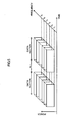
- FIG. 2 is an explanatory diagram for describing the radio signal used in OFDM.
- the vertical axis represents a frequency axis
- the horizontal axis represents a time axis.
- Individual rectangles represent transmission units of the radio signal.
- a time length of the transmission unit is equal to a time slot length.
- a symbol (signal point indicating data of one or more bits, which is obtained from single modulation) sequence is mapped onto a complex plane for each series of symbols (hereinafter, referred to as unit symbol sequence), the number of which is in accordance with a GI length.
- unit symbol sequence After D/A conversion, the mapped symbol sequence is subjected to inverse fast Fourier transform.
- the above-mentioned symbol sequence is dispersed among multiple sub-carriers on a unit-symbol-sequence basis.
- the above-mentioned transmission unit is made of the unit symbol sequence thus dispersed.
- FIG. 3 illustrates a content of the above-mentioned unit symbol sequence in detail.
- each unit symbol sequence includes a plurality of symbols, and each symbol includes a GI and a data section.
- the data section includes an analog signal that indicates a symbol and has a predetermined time length.
- the GI may be configured to include part (normally, analog signal ranging over GI length from end of data section) of the analog signal constituting the data section, or not to include a significant signal.
- the GI removal unit 12 removes the GIs from the radio signal that is input from the RF/IF/BB unit 11, and then outputs the resultant signal to the FFT unit 13.
- the FFT unit 13 carries out fast Fourier transform with respect to the radio signal input from the GI removal unit 12. As a result, the FFT unit 13 acquires, for each transmission unit described above, a unit symbol sequence prior to inverse fast Fourier transform, and then outputs the acquired unit symbol sequence to the correlation calculation unit 14. It should be noted that the unit symbol sequence thus acquired includes interference components and noise components.
- the above-mentioned unit symbol sequence includes a known signal portion (also referred to as unique word). Further, the known signal holding unit 15 holds a signal having the same waveform as that of this known signal portion.
- the correlation calculation unit 14 calculates a correlation between the unit symbol sequence input from the FFT unit 13 and a held signal that is held by the known signal holding unit 15 and has the same waveform as that of the above-mentioned known signal. Through this processing, the correlation calculation unit 14 judges that a part showing the largest correlation value is the known signal portion within the unit symbol sequence. Then, the result of the judgment and the unit symbol sequence are output to the demodulation/decoding unit 16.
- unit symbol sequence is dispersed in terms of time, and hence some identical unit symbol sequences are received.
- unit symbol sequences dispersed in terms of time unit symbol sequences except for the first one (which is regarded as reception symbol) are all delay components. In a case where such delay components are present, the correlation calculation unit 14 judges that a plurality of portions correspond to the known signal portion.
- FIG. 4(a) exemplifies a delay profile illustrating a delay component for each path in a case of multipath reception of a symbol.
- some identical symbols delay components
- FIG. 4(a) only the reception symbol and the delay components with respect to a single symbol are illustrated, but the degrees of delay for the respective symbols included in a unit symbol sequence can be regarded substantially the same.
- the demodulation/decoding unit 16 acquires the reception timing of the known signal portion based on the input result of the judgment. If the above-mentioned delay components are present, the demodulation/decoding unit 16 acquires a plurality of the reception timings. In accordance with the first reception timing of the plurality of the reception timings thus acquired, the demodulation/decoding unit 16 demodulates each unit symbol sequence with a modulation scheme used for modulating each unit symbol sequence concerned. The demodulation/decoding unit 16 further decodes, with a predetermined encoding method, a bit sequence obtained as the result of the demodulation, and then outputs the decoded bit sequence to the received data acquisition unit 17. The received data acquisition unit 17 acquires received data based on the bit sequence that is input from the demodulation/decoding unit 16.
- the symbol delay amount acquisition unit 18 acquires the amount of a delay component (symbol delay amount) based on the result of the calculation from the correlation calculation unit 14. Specifically, the symbol delay amount acquisition unit 18 acquires, as the symbol delay amount, the degree of delay for each of the plurality of the delay components.
- the desired signal power acquisition unit 19 acquires, based on the result of the calculation from the correlation calculation unit 14, a desired signal power for the reception symbol and each of the plurality of the delay components.
- the symbol delay interference wave power acquisition unit 20 acquires a "symbol delay interference wave” power (denoted as I), which is an interference wave power in a case where a certain symbol becomes an interference wave against the subsequent symbol, based on the desired signal powers of the delay components acquired by the desired signal power acquisition unit 19 and the symbol delay amount acquired by the symbol delay amount acquisition unit 18. Specifically, the symbol delay interference wave power acquisition unit 20 acquires the "symbol delay interference wave” power I by summing up the desired signal powers of the unit symbol sequences that have their symbol delay amounts exceeding the GI length.
- I symbol delay interference wave
- FIG. 4 (b) illustrates a specific example of the "symbol delay interference wave" power I.As illustrated in FIG. 4(b) , the "symbol delay interference wave" power I represents a power of a portion in which some delay components of a certain symbol that exceed the GI length overlap the subsequent reception symbol.
- the frequency fluctuation amount information acquisition unit 21 acquires frequency fluctuation amount information which indicates the amount of a frequency fluctuation of the unit symbol sequence acquired by the FFT unit 13.
- the amount of a frequency fluctuation is described in detail.
- the frequency fluctuation refers to a frequency change of a unit symbol sequence, which occurs due to the Doppler effect or the like. In many cases, the frequency fluctuation is frequency selective, and therefore occurs only in some sub-carriers.
- FIG. 5 illustrates a specific example of the frequency fluctuation.
- sub-carriers having frequencies f 1 to f 6 are illustrated, and the frequency fluctuation occurs in the vicinity of a frequency f 3 .
- the frequency of the sub-carrier originally having the frequency f 3 is shifted from the frequency f 3 .
- the phase of the reception symbol becomes shifted from the original phase.
- the reception timing of the data section is determined based on the reception timing of the known signal portion acquired in the above-mentioned manner. If the frequency of the signal concerned is not shifted from the original frequency, the phase of that signal received at the above-mentioned reception timing corresponds to the original phase, but if the frequency is shifted, the phase becomes shifted from the original phase because the signal is extended or shortened in the time axis direction.
- the phase shift error thus generated affects the reception of the symbol as noise (frequency fluctuation noise).
- the frequency fluctuation amount information acquisition unit 21 acquires, for each symbol and sub-carrier, a change amount of the phase within a predetermined period of time (e.g., within period for update of GI length), and then acquires the frequency fluctuation amount information based on the acquired change amount of the phase.
- the frequency fluctuation amount information is calculated with the following Expression (1).
- m represents serial numbers assigned to symbols within the above-mentioned predetermined period of time (here, 1 to M); k, serial numbers of sub-carriers (here, 1 to K) ; ⁇ mk , a signal vector angle (phase) in the case of a symbol number m and a sub-carrier number k; ⁇ mkr , an original signal vector angle (phase) in the case of the symbol number m and the sub-carrier number k; and N ⁇ , the frequency fluctuation amount information.
- ⁇ mkr a vector average angle within the above-mentioned predetermined period of time, which is obtained after modulation signal components are removed, may be used.
- the frequency fluctuation noise power acquisition unit 22 converts, from angle to power, the unit of the frequency fluctuation amount acquired by the frequency fluctuation amount information acquisition unit 21, and then acquires a frequency fluctuation noise power.
- a frequency fluctuation noise power N is acquired.
- S represents a desired signal power of the reception symbol acquired by the desired signal power acquisition unit 19
- ⁇ represents a proportional multiplier determined based on the modulation scheme. For example, in the case of QPSK, based on a maximum phase change ⁇ /4 [rad], at which the demodulation becomes impossible, ⁇ is determined as ⁇ /4.
- N S ⁇ ⁇ ⁇ N ⁇ ⁇ M ⁇ K
- the GI length determination/instruction unit 23 determines the GI length in accordance with the frequency fluctuation noise power N acquired by the frequency fluctuation noise power acquisition unit 22 and the "symbol delay interference wave" power I acquired by the symbol delay interference wave power acquisition unit 20.
- the necessary symbol delay interference wave power calculation unit 24 calculates the necessary "symbol delay interference wave" power I MAX for setting an SINR to a predetermined value (minimum required SINR for establishing communication), based on the frequency fluctuation noise power N acquired by the frequency fluctuation noise power acquisition unit 22.
- the GI length determination/instruction unit 23 determines the GI length based on the necessary "symbol delay interference wave” power I MAX thus calculated and the "symbol delay interference wave” power I acquired by the symbol delay interference wave power acquisition unit 20.
- the GI length determination/instruction unit 23 determines the GI length such that the "symbol delay interference wave" power acquired by the symbol delay interference wave power acquisition unit 20 becomes equal to the necessary "symbol delay interference wave” power I MAX .
- the GI length determination/instruction unit 23 determines the GI length as described above, the GI length determination/instruction unit 23 instructs the communication partner to transmit the symbols with that GI length. Specifically, the GI length determination/instruction unit 23 generates GI length instruction information that specifies the GI length for instruction, and then outputs the GI length instruction information to the physical layer frame generation unit 26. Consequently, the GI length instruction information is transmitted to the communication partner.
- the GI length instruction information is transmitted to the communication partner.
- the transmission data acquisition unit 25 acquires a bit sequence constituting transmission data.
- the physical layer frame generation unit 26 adds a physical layer header to the bit sequence acquired by the transmission data acquisition unit 25, and then outputs the resultant bit sequence to the encoding/modulation unit 27. At this point, the physical layer frame generation unit 26 puts into the physical layer header the GI length instruction information that is input from the GI length determination/instruction unit 23.
- the encoding/modulation unit 27 encodes the transmission data, which is input from the physical layer frame generation unit 26 after the physical layer header is added, with a predetermined encoding method, thereby acquiring encoded data. Further, the encoding/modulation unit 27 modulates the encoded data with a given modulation scheme to generate a symbol sequence, and then outputs the generated symbol sequence to the IFFT unit 29. It is preferable that the modulation scheme used by the encoding/modulation unit 27 for modulating the encoded data be changed as necessary in accordance with the radio condition (reception condition) by employing an adaptive modulation scheme.
- the GI length instruction acquisition unit 28 acquires, from the received data acquired by the received data acquisition unit 17, the GI length instruction information transmitted from the communication partner through processing similar to the case of the OFDM communication device 10 concerned.
- the IFFT unit 29 determines the number of symbols to be included in a unit symbol sequence based on the GI length instruction information acquired by the GI length instruction acquisition unit 28. In this determination, as the GI length becomes longer, the number of symbols becomes smaller. Then, the IFFT unit 29 divides the symbol sequence input from the encoding/modulation unit 27 into unit symbol sequences, which are then mapped onto the complex plane. After D/A conversion, the IFFT unit 29 executes inverse fast Fourier transform. As a result, the symbol sequence is dispersed among multiple sub-carriers on a unit-symbol-sequence basis. The IFFT unit 29 outputs the signal thus obtained to the GI addition unit 30.
- the GI addition unit 30 adds a GI, which has a length determined based on the GI length instruction information acquired by the GI length instruction acquisition unit 28, to the head of each symbol constituting the unit symbol sequence, and then outputs the signal to the RF/IF/BB unit 11.
- the RF/IF/BB unit 11 wirelessly transmits the signal that is input from the GI addition unit 30 by means of the super-heterodyne system.
- FIG. 6 is a diagram illustrating the processing flow of the OFDM communication device 10. As illustrated in FIG. 6 , the OFDM communication device 10 first acquires a minimum required SINR for establishing communication. Hereinafter, this SINR is referred to as SINR 1 (S1).
- SINR 1 SINR 1
- the OFDM communication device 10 compares I calculated in S2 and I MAX calculated in S6, and then performs different processing in accordance with its result (S7).
- I is smaller than I MAX , communication canbe established even if I is set larger. Accordingly, in order to make I larger, the OFDM communication device 10 determines, in accordance with a difference between I and I MAX , a GI length control amount in such a manner as to shorten the GI length (S8).
- the GI length control amount is determined as 0 so as to maintain the current I (S9).
- the OFDM communication device 10 determines, in accordance with the difference between I and I MAX , the GI length control amount in such a manner as to extend the GI length (S10).
- the OFDM communication device 10 determines the GI length based on the GI length control amount thus determined and the current GI length (S11).
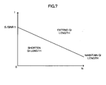
- FIG. 7 is a diagram illustrating a relation between the GI length thus determined, and the frequency fluctuation noise power N and the "symbol delay interference wave" power I.As illustrated in FIG. 7 , even if the "symbol delay interference wave" power I is small, if the frequency fluctuation noise power N is large, the GI length is more likely to be subjected to extending control. Conversely, even if the "symbol delay interference wave" power I is large, when the frequency fluctuation noise power N is small, the GI length is more likely to be subjected to shortening control.
- the OFDM communication device 10 transmits the GI length instruction information to the communication partner, thereby notifying the communication partner of the GI length (S12). From then on, the communication partner who has received the GI length instruction information starts to transmit a unit symbol sequence having the GI length specified by the GI length instruction information.
- the GI length can be determined in accordance with both the amount of the frequency fluctuation and the "symbol delay interference wave" power.
- the OFDM communication device 10 can control the GI length so that the minimum required SINR can be obtained even if the frequency fluctuation is present.
Landscapes
- Engineering & Computer Science (AREA)
- Computer Networks & Wireless Communication (AREA)
- Signal Processing (AREA)
- Mobile Radio Communication Systems (AREA)
- Transceivers (AREA)
Abstract
Description
- The present invention relates to an OFDM communication device and a guard interval length determining method.
- In orthogonal frequency division multiplexing (OFDM), if a certain symbol contains a delay component, the delay component becomes an interference wave against the subsequent symbol, resulting in a decline of a signal to interference and noise ratio (SINR) of the subsequent symbol. In order to prevent this, a guard interval (GI) is provided at the head of the symbol.
- In
Patent Document 1, there is described a technology of controlling a guard interval length in accordance with an amount of the delay component. In general, the SINR increases as the guard interval becomes longer, but this causes the communication rate to decrease. With this technology, the guard interval length is so determined that a minimum required SINR can be obtained to maximize the communication rate. - Further, in Patent Document 2, there is disclosed a technology of reducing, in a case where the same sub-carriers are transmitted from a plurality of transmission devices (for example, at the time of handover), interference between symbols that are transmitted from each of the transmission devices. Further, in Patent Document 3, there is disclosed a technology of improving frequency usage efficiency in OFDM.
Patent Document 1:JP 2002-374223 A
Patent Document 2:JP 2005-303826 A
Patent Document 3:JP 2005-252886 A - However, the SINR is affected not only by an interference wave (hereinafter, referred to as "symbol delay interference wave") due to the delay component, but also by a frequency fluctuation due to the Doppler effect or the like. Thus, even with the technology described in
Patent Document 1, there occur some cases in which a minimum required SINR cannot be obtained. - Specifically, in OFDM, in order to determine a reception timing of a symbol, there is used a known signal. The initial phase of the known signal is known in advance, and hence a communication device on the reception side determines the reception timing of the symbol so that the known signal can be received in a correct initial phase.
- However, even if the reception timing of the symbol is determined in this manner, the frequency fluctuation causes the time length of each symbol to be extended or shortened, which results in shift of the phase thereof. This shift acts as noise (hereinafter, referred to as frequency fluctuation noise) when the symbol is received.
- The SINR is obtained by dividing a "desired signal" power by an "interference wave and noise" power, and the "interference wave and noise" includes both the "symbol delay interference wave" and the frequency fluctuation noise. Hence, even if the guard interval length is controlled in accordance with the amount of the delay component of the symbol, the minimum required SINR cannot be obtained in some cases.
- Therefore, an object of the present invention is to provide an OFDM communication device and a guard interval length determining method, which are capable of controlling a guard interval length so that a minimum required SINR can be obtained even if frequency fluctuation is present.
- In order to solve the above-mentioned problem, an OFDM communication device according to the present invention includes: a reception unit for receiving a series of symbols; a detection unit for detecting a frequency fluctuation of the series of symbols received by the reception unit; a frequency fluctuation amount information acquisition unit for acquiring frequency fluctuation amount information that indicates an amount of the frequency fluctuation detected by the detection unit; a guard interval length determination unit for determining a guard interval length in accordance with the frequency fluctuation amount information acquired by the frequency fluctuation amount information acquisition unit; and a guard interval length instruction unit for instructing a transmission device to transmit symbols with the guard interval length determined by the guard interval length determination unit.
- With this configuration, the guard interval length is determined in accordance with the frequency fluctuation amount information. Hence, the above-mentioned OFDM communication device can control the guard interval length so that the minimum required SINR can be obtained even if the frequency fluctuation is present.
- Further, in the above-mentioned OFDM communication device, the series of symbols may contain a known signal portion. The OFDM communication device may further include: a correlation calculation unit for calculating a correlation between the series of symbols received by the reception unit and a held signal that has a waveform identical to a waveform of the known signal portion; a desired signal power acquisition unit for acquiring a desired signal power based on a calculation result from the correlation calculation unit; a symbol delay amount acquisition unit for acquiring a symbol delay amount based on the calculation result from the correlation calculation unit; and a symbol delay interference wave power acquisition unit for acquiring a symbol delay interference wave power, which is an interference wave power in a case where a certain symbol becomes an interference wave against a subsequent symbol, based on the desired signal power acquired by the desired signal power acquisition unit and the symbol delay amount acquired by the symbol delay amount acquisition unit. The guard interval length determination unit may determine the guard interval length in accordance with the frequency fluctuation amount information acquired by the frequency fluctuation amount information acquisition unit and the symbol delay interference wave power acquired by the symbol delay interference wave power acquisition unit.
- With this configuration, the guard interval length is determined in accordance with both the frequency fluctuation amount information and the symbol delay interference wave power. Hence, the above-mentioned OFDM communication device can control the guard interval length so that the minimum required SINR can be obtained more preferably even if the frequency fluctuation is present.
- Further, in the above-mentioned OFDM communication device, the guard interval length determination unit may include a necessary symbol delay interference wave power calculation unit for calculating a necessary symbol delay interference wave power required for setting an SINR to a predetermined value, based on the frequency fluctuation amount information acquired by the frequency fluctuation amount information acquisition unit. The guard interval length determination unit may determine the guard interval length based on the necessary symbol delay interference wave power calculated by the necessary symbol delay interference wave power calculation unit and the symbol delay interference wave power acquired by the symbol delay interference wave power acquisition unit.
- With this configuration, while taking the frequency fluctuation amount information into account, the guard interval length can be so determined that the SINR becomes the predetermined value.
- Further, a guard interval length determining method according to the present invention includes: a reception step of receiving a series of symbols; a detection step of detecting a frequency fluctuation of the series of symbols received by the reception unit; a frequency fluctuation amount information acquisition step of acquiring frequency fluctuation amount information that indicates an amount of the frequency fluctuation detected in the detection step; a guard interval length determination step of determining a guard interval length in accordance with the frequency fluctuation amount information acquired in the frequency fluctuation amount information acquisition step; and a guard interval length instruction step of instructing a transmission device to transmit symbols with the guard interval length determined in the guard interval length determination step.
-
-
FIG. 1 is a diagram illustrating a system configuration and functional blocks of an OFDM communication device according to an embodiment of the present invention. -
FIG. 2 is an explanatory diagram for describing a radio signal according to the embodiment of the present invention. -
FIG. 3 is an explanatory diagram for describing symbols according to the embodiment of the present invention. -
FIGS. 4 are diagrams for describing delay of a symbol according to the embodiment of the present invention.FIG. 4 (a) exemplifies a delay profile illustrating a delay amount for each path in a case of multipath reception of a symbol.FIG. 4 (b) exemplifies a "symbol delay interference wave" power. -
FIG. 5 is a diagram illustrating an example of a frequency fluctuation according to the embodiment of the present invention. -
FIG. 6 is a diagram illustrating a processing flow of the OFDM communication device according to the embodiment of the present invention. -
FIG. 7 is a diagram illustrating a relation between a GI length, and a frequency fluctuation noise power and a "symbol delay interference wave" power according to the embodiment of the present invention. - With reference to the drawings, an embodiment of the present invention is described.
-
FIG. 1 is a diagram illustrating a system configuration and functional blocks of anOFDM communication device 10 according to this embodiment. As illustrated inFIG. 1 , in terms of functions, theOFDM communication device 10 includes a radio frequency (RF) /inter-frequency (IF) /base band (BB)unit 11, aGI removal unit 12, a fast Fourier transform (FFT)unit 13, acorrelation calculation unit 14, a knownsignal holding unit 15, a demodulation/decoding unit 16, a receiveddata acquisition unit 17, a symbol delayamount acquisition unit 18, a desired signalpower acquisition unit 19, a symbol delay interference wavepower acquisition unit 20, a frequency fluctuation amountinformation acquisition unit 21, a frequency fluctuation noisepower acquisition unit 22, a GI length determination/instruction unit 23, a transmissiondata acquisition unit 25, a physical layerframe generation unit 26, an encoding/modulation unit 27, a GI lengthinstruction acquisition unit 28, an inverse fast Fourier transform (IFFT)unit 29, and aGI addition unit 30. Further, the GI length determination/instruction unit 23 includes a necessary symbol delay interference wavepower calculation unit 24. - The
OFDM communication device 10 is a communication device used as a mobile station device or a base station device in a mobile communication system, and performs communications by means of OFDM. It should be noted that a communication partner of theOFDM communication device 10 is also a communication device similar to theOFDM communication device 10. Hereinbelow, functions of the above-mentioned respective units that are included in theOFDM communication device 10 are described specifically. - The RF/IF/
BB unit 11 receives a radio signal transmitted from the communication partner by means of a super-heterodyne system, and outputs the received signal to theGI removal unit 12. - A description is now made of a radio signal used in OFDM.
-
FIG. 2 is an explanatory diagram for describing the radio signal used in OFDM. InFIG. 2 , the vertical axis represents a frequency axis, whereas the horizontal axis represents a time axis. Individual rectangles represent transmission units of the radio signal. A time length of the transmission unit is equal to a time slot length. - In OFDM, a symbol (signal point indicating data of one or more bits, which is obtained from single modulation) sequence is mapped onto a complex plane for each series of symbols (hereinafter, referred to as unit symbol sequence), the number of which is in accordance with a GI length. After D/A conversion, the mapped symbol sequence is subjected to inverse fast Fourier transform. As a result, the above-mentioned symbol sequence is dispersed among multiple sub-carriers on a unit-symbol-sequence basis. The above-mentioned transmission unit is made of the unit symbol sequence thus dispersed.
-
FIG. 3 illustrates a content of the above-mentioned unit symbol sequence in detail. As illustrated inFIG. 3 , each unit symbol sequence includes a plurality of symbols, and each symbol includes a GI and a data section. The data section includes an analog signal that indicates a symbol and has a predetermined time length. The GI may be configured to include part (normally, analog signal ranging over GI length from end of data section) of the analog signal constituting the data section, or not to include a significant signal. - The
GI removal unit 12 removes the GIs from the radio signal that is input from the RF/IF/BB unit 11, and then outputs the resultant signal to theFFT unit 13. - The
FFT unit 13 carries out fast Fourier transform with respect to the radio signal input from theGI removal unit 12. As a result, theFFT unit 13 acquires, for each transmission unit described above, a unit symbol sequence prior to inverse fast Fourier transform, and then outputs the acquired unit symbol sequence to thecorrelation calculation unit 14. It should be noted that the unit symbol sequence thus acquired includes interference components and noise components. - Here, the above-mentioned unit symbol sequence includes a known signal portion (also referred to as unique word). Further, the known
signal holding unit 15 holds a signal having the same waveform as that of this known signal portion. Thecorrelation calculation unit 14 calculates a correlation between the unit symbol sequence input from theFFT unit 13 and a held signal that is held by the knownsignal holding unit 15 and has the same waveform as that of the above-mentioned known signal. Through this processing, thecorrelation calculation unit 14 judges that a part showing the largest correlation value is the known signal portion within the unit symbol sequence. Then, the result of the judgment and the unit symbol sequence are output to the demodulation/decoding unit 16. - Here, in some cases, due to the influence of multipath or the like, the above-mentioned unit symbol sequence is dispersed in terms of time, and hence some identical unit symbol sequences are received. Of the unit symbol sequences dispersed in terms of time, unit symbol sequences except for the first one (which is regarded as reception symbol) are all delay components. In a case where such delay components are present, the
correlation calculation unit 14 judges that a plurality of portions correspond to the known signal portion. -
FIG. 4(a) exemplifies a delay profile illustrating a delay component for each path in a case of multipath reception of a symbol. As illustrated inFIG. 4(a) , in the case of the multipath reception, some identical symbols (delay components) which are dispersed at a plurality of slightly different timings are received. It should be noted that, inFIG. 4(a) , only the reception symbol and the delay components with respect to a single symbol are illustrated, but the degrees of delay for the respective symbols included in a unit symbol sequence can be regarded substantially the same. - The demodulation/
decoding unit 16 acquires the reception timing of the known signal portion based on the input result of the judgment. If the above-mentioned delay components are present, the demodulation/decoding unit 16 acquires a plurality of the reception timings. In accordance with the first reception timing of the plurality of the reception timings thus acquired, the demodulation/decoding unit 16 demodulates each unit symbol sequence with a modulation scheme used for modulating each unit symbol sequence concerned. The demodulation/decoding unit 16 further decodes, with a predetermined encoding method, a bit sequence obtained as the result of the demodulation, and then outputs the decoded bit sequence to the receiveddata acquisition unit 17. The receiveddata acquisition unit 17 acquires received data based on the bit sequence that is input from the demodulation/decoding unit 16. - The symbol delay
amount acquisition unit 18 acquires the amount of a delay component (symbol delay amount) based on the result of the calculation from thecorrelation calculation unit 14. Specifically, the symbol delayamount acquisition unit 18 acquires, as the symbol delay amount, the degree of delay for each of the plurality of the delay components. - Further, the desired signal
power acquisition unit 19 acquires, based on the result of the calculation from thecorrelation calculation unit 14, a desired signal power for the reception symbol and each of the plurality of the delay components. - The symbol delay interference wave
power acquisition unit 20 acquires a "symbol delay interference wave" power (denoted as I), which is an interference wave power in a case where a certain symbol becomes an interference wave against the subsequent symbol, based on the desired signal powers of the delay components acquired by the desired signalpower acquisition unit 19 and the symbol delay amount acquired by the symbol delayamount acquisition unit 18. Specifically, the symbol delay interference wavepower acquisition unit 20 acquires the "symbol delay interference wave" power I by summing up the desired signal powers of the unit symbol sequences that have their symbol delay amounts exceeding the GI length. -
FIG. 4 (b) illustrates a specific example of the "symbol delay interference wave" power I.As illustrated inFIG. 4(b) , the "symbol delay interference wave" power I represents a power of a portion in which some delay components of a certain symbol that exceed the GI length overlap the subsequent reception symbol. - The frequency fluctuation amount
information acquisition unit 21 acquires frequency fluctuation amount information which indicates the amount of a frequency fluctuation of the unit symbol sequence acquired by theFFT unit 13. Hereinbelow, the amount of a frequency fluctuation is described in detail. - The frequency fluctuation refers to a frequency change of a unit symbol sequence, which occurs due to the Doppler effect or the like. In many cases, the frequency fluctuation is frequency selective, and therefore occurs only in some sub-carriers.
-
FIG. 5 illustrates a specific example of the frequency fluctuation. InFIG. 5 , sub-carriers having frequencies f1 to f6 are illustrated, and the frequency fluctuation occurs in the vicinity of a frequency f3. As a result, the frequency of the sub-carrier originally having the frequency f3 is shifted from the frequency f3. - When such a frequency fluctuation is present, the phase of the reception symbol becomes shifted from the original phase. Specifically, the reception timing of the data section is determined based on the reception timing of the known signal portion acquired in the above-mentioned manner. If the frequency of the signal concerned is not shifted from the original frequency, the phase of that signal received at the above-mentioned reception timing corresponds to the original phase, but if the frequency is shifted, the phase becomes shifted from the original phase because the signal is extended or shortened in the time axis direction. The phase shift error thus generated affects the reception of the symbol as noise (frequency fluctuation noise).
- The frequency fluctuation amount
information acquisition unit 21 acquires, for each symbol and sub-carrier, a change amount of the phase within a predetermined period of time (e.g., within period for update of GI length), and then acquires the frequency fluctuation amount information based on the acquired change amount of the phase. Specifically, the frequency fluctuation amount information is calculated with the following Expression (1). In Expression (1), m represents serial numbers assigned to symbols within the above-mentioned predetermined period of time (here, 1 to M); k, serial numbers of sub-carriers (here, 1 to K) ; θmk, a signal vector angle (phase) in the case of a symbol number m and a sub-carrier number k; θmkr, an original signal vector angle (phase) in the case of the symbol number m and the sub-carrier number k; and Nθ, the frequency fluctuation amount information. It should be noted that, for θmkr, a vector average angle within the above-mentioned predetermined period of time, which is obtained after modulation signal components are removed, may be used.
- The frequency fluctuation noise
power acquisition unit 22 converts, from angle to power, the unit of the frequency fluctuation amount acquired by the frequency fluctuation amountinformation acquisition unit 21, and then acquires a frequency fluctuation noise power. Specifically, with the following Expression (2), a frequency fluctuation noise power N is acquired. Here, S represents a desired signal power of the reception symbol acquired by the desired signalpower acquisition unit 19, and α represents a proportional multiplier determined based on the modulation scheme. For example, in the case of QPSK, based on a maximum phase change ±π/4 [rad], at which the demodulation becomes impossible, α is determined as π/4.
- The GI length determination/
instruction unit 23 determines the GI length in accordance with the frequency fluctuation noise power N acquired by the frequency fluctuation noisepower acquisition unit 22 and the "symbol delay interference wave" power I acquired by the symbol delay interference wavepower acquisition unit 20. - Specifically, the necessary symbol delay interference wave
power calculation unit 24 calculates the necessary "symbol delay interference wave" power IMAX for setting an SINR to a predetermined value (minimum required SINR for establishing communication), based on the frequency fluctuation noise power N acquired by the frequency fluctuation noisepower acquisition unit 22. The GI length determination/instruction unit 23 determines the GI length based on the necessary "symbol delay interference wave" power IMAX thus calculated and the "symbol delay interference wave" power I acquired by the symbol delay interference wavepower acquisition unit 20. More specifically, the GI length determination/instruction unit 23 determines the GI length such that the "symbol delay interference wave" power acquired by the symbol delay interference wavepower acquisition unit 20 becomes equal to the necessary "symbol delay interference wave" power IMAX. - After the GI length determination/
instruction unit 23 determines the GI length as described above, the GI length determination/instruction unit 23 instructs the communication partner to transmit the symbols with that GI length. Specifically, the GI length determination/instruction unit 23 generates GI length instruction information that specifies the GI length for instruction, and then outputs the GI length instruction information to the physical layerframe generation unit 26. Consequently, the GI length instruction information is transmitted to the communication partner. Hereinbelow, referring to the details thereof, the transmission of the symbols by theOFDM communication device 10 is described. - The transmission
data acquisition unit 25 acquires a bit sequence constituting transmission data. The physical layerframe generation unit 26 adds a physical layer header to the bit sequence acquired by the transmissiondata acquisition unit 25, and then outputs the resultant bit sequence to the encoding/modulation unit 27. At this point, the physical layerframe generation unit 26 puts into the physical layer header the GI length instruction information that is input from the GI length determination/instruction unit 23. - The encoding/
modulation unit 27 encodes the transmission data, which is input from the physical layerframe generation unit 26 after the physical layer header is added, with a predetermined encoding method, thereby acquiring encoded data. Further, the encoding/modulation unit 27 modulates the encoded data with a given modulation scheme to generate a symbol sequence, and then outputs the generated symbol sequence to theIFFT unit 29. It is preferable that the modulation scheme used by the encoding/modulation unit 27 for modulating the encoded data be changed as necessary in accordance with the radio condition (reception condition) by employing an adaptive modulation scheme. - The GI length
instruction acquisition unit 28 acquires, from the received data acquired by the receiveddata acquisition unit 17, the GI length instruction information transmitted from the communication partner through processing similar to the case of theOFDM communication device 10 concerned. - The
IFFT unit 29 determines the number of symbols to be included in a unit symbol sequence based on the GI length instruction information acquired by the GI lengthinstruction acquisition unit 28. In this determination, as the GI length becomes longer, the number of symbols becomes smaller. Then, theIFFT unit 29 divides the symbol sequence input from the encoding/modulation unit 27 into unit symbol sequences, which are then mapped onto the complex plane. After D/A conversion, theIFFT unit 29 executes inverse fast Fourier transform. As a result, the symbol sequence is dispersed among multiple sub-carriers on a unit-symbol-sequence basis. TheIFFT unit 29 outputs the signal thus obtained to theGI addition unit 30. - The
GI addition unit 30 adds a GI, which has a length determined based on the GI length instruction information acquired by the GI lengthinstruction acquisition unit 28, to the head of each symbol constituting the unit symbol sequence, and then outputs the signal to the RF/IF/BB unit 11. - The RF/IF/
BB unit 11 wirelessly transmits the signal that is input from theGI addition unit 30 by means of the super-heterodyne system. - With regard to the processing described above, the description therefor is made in more details with reference to a processing flow of the
OFDM communication device 10. -
FIG. 6 is a diagram illustrating the processing flow of theOFDM communication device 10. As illustrated inFIG. 6 , theOFDM communication device 10 first acquires a minimum required SINR for establishing communication. Hereinafter, this SINR is referred to as SINR 1 (S1). - Upon receiving a signal (S2), the
OFDM communication device 10 calculates the desired signal reception power S (S3), the "symbol delay interference wave" power I (S4), and the frequency fluctuation noisepowerN (S5) as described above. Aftercalculatingthosepowers, theOFDM communication device 10 calculates the maximum value IMAX for I, with which communication can be established. In other words, theOFDM communication device 10 calculates the maximum value IMAX for I, which is an allowable value if the frequency fluctuation noise power N is present. Specifically, the maximum value IMAX is calculated with the following Expression (3) (S6).
- The
OFDM communication device 10 compares I calculated in S2 and IMAX calculated in S6, and then performs different processing in accordance with its result (S7). When I is smaller than IMAX, communication canbe established even if I is set larger. Accordingly, in order to make I larger, theOFDM communication device 10 determines, in accordance with a difference between I and IMAX, a GI length control amount in such a manner as to shorten the GI length (S8). When I is equal to IMAX, the GI length control amount is determined as 0 so as to maintain the current I (S9). When I is larger than IMAX, communication cannot be established with the current state. Accordingly, in order to make I smaller, theOFDM communication device 10 determines, in accordance with the difference between I and IMAX, the GI length control amount in such a manner as to extend the GI length (S10). - The
OFDM communication device 10 determines the GI length based on the GI length control amount thus determined and the current GI length (S11). -
FIG. 7 is a diagram illustrating a relation between the GI length thus determined, and the frequency fluctuation noise power N and the "symbol delay interference wave" power I.As illustrated inFIG. 7 , even if the "symbol delay interference wave" power I is small, if the frequency fluctuation noise power N is large, the GI length is more likely to be subjected to extending control. Conversely, even if the "symbol delay interference wave" power I is large, when the frequency fluctuation noise power N is small, the GI length is more likely to be subjected to shortening control. - Lastly, the
OFDM communication device 10 transmits the GI length instruction information to the communication partner, thereby notifying the communication partner of the GI length (S12). From then on, the communication partner who has received the GI length instruction information starts to transmit a unit symbol sequence having the GI length specified by the GI length instruction information. - As described above, with the
OFDM communication device 10, the GI length can be determined in accordance with both the amount of the frequency fluctuation and the "symbol delay interference wave" power. With this configuration, theOFDM communication device 10 can control the GI length so that the minimum required SINR can be obtained even if the frequency fluctuation is present.
Claims (4)
- An OFDM communication device, comprising:a reception unit for receiving a series of symbols;a frequency fluctuation amount information acquisition unit for acquiring frequency fluctuation amount information that indicates a frequency fluctuation amount of the series of symbols received by the reception unit;a guard interval length determination unit for determining a guard interval length in accordance with the frequency fluctuation amount information acquired by the frequency fluctuation amount information acquisition unit; anda guard interval length instruction unit for instructing a transmission device to transmit symbols with the guard interval length determined by the guard interval length determination unit.
- An OFDM communication device according to Claim 1, wherein the series of symbols contain a known signal portion,
wherein the OFDM communication device further comprises:a correlation calculation unit for calculating a correlation between the series of symbols received by the reception unit and a held signal that has a waveform identical to a waveform of the known signal portion;a desired signal power acquisition unit for acquiring a desired signal power based on a calculation result from the correlation calculation unit;a symbol delay amount acquisition unit for acquiring a symbol delay amount based on the calculation result from the correlation calculation unit; anda symbol delay interference wave power acquisition unit for acquiring a symbol delay interference wave power, which is an interference wave power in a case where a certain symbol becomes an interference wave against a subsequent symbol, based on the desired signal power acquired by the desired signal power acquisition unit and the symbol delay amount acquired by the symbol delay amount acquisition unit, andwherein the guard interval length determination unit determines the guard interval length in accordance with the frequency fluctuation amount information acquired by the frequency fluctuation amount information acquisition unit and the symbol delay interference wave power acquired by the symbol delay interference wave power acquisition unit. - An OFDM communication device according to Claim 2, wherein
the guard interval length determination unit comprises a necessary symbol delay interference wave power calculation unit for calculating a necessary symbol delay interference wave power required for setting an SINR to a predetermined value, based on the frequency fluctuation amount information acquired by the frequency fluctuation amount information acquisition unit, and
the guard interval length determination unit determines the guard interval length based on the necessary symbol delay interference wave power calculated by the necessary symbol delay interference wave power calculation unit and the symbol delay interference wave power acquired by the symbol delay interference wave power acquisition unit. - A guard interval length determining method, comprising:a reception step of receiving a series of symbols;a frequency fluctuation amount information acquisition step of acquiring frequency fluctuation amount information that indicates a frequency fluctuation amount of the series of symbols received in the reception step;a guard interval length determination step of determining a guard interval length in accordance with the frequency fluctuation amount information acquired in the frequency fluctuation amount information acquisition step; anda guard interval length instruction step of instructing a transmission device to transmit symbols with the guard interval length determined in the guard interval length determination step.
Applications Claiming Priority (2)
| Application Number | Priority Date | Filing Date | Title |
|---|---|---|---|
| JP2006218526A JP4927471B2 (en) | 2006-08-10 | 2006-08-10 | OFDM communication apparatus and guard interval length determination method |
| PCT/JP2007/065462 WO2008018470A1 (en) | 2006-08-10 | 2007-08-07 | Ofdm communication device and guard interval length determining method |
Publications (2)
| Publication Number | Publication Date |
|---|---|
| EP2053768A1 true EP2053768A1 (en) | 2009-04-29 |
| EP2053768A4 EP2053768A4 (en) | 2011-07-06 |
Family
ID=39033000
Family Applications (1)
| Application Number | Title | Priority Date | Filing Date |
|---|---|---|---|
| EP07792131A Withdrawn EP2053768A4 (en) | 2006-08-10 | 2007-08-07 | OFDM COMMUNICATION DEVICE AND METHOD FOR DETERMINING KEEP INTERVAL LENGTH |
Country Status (6)
| Country | Link |
|---|---|
| US (1) | US8254477B2 (en) |
| EP (1) | EP2053768A4 (en) |
| JP (1) | JP4927471B2 (en) |
| KR (1) | KR100993424B1 (en) |
| CN (1) | CN101502030B (en) |
| WO (1) | WO2008018470A1 (en) |
Families Citing this family (10)
| Publication number | Priority date | Publication date | Assignee | Title |
|---|---|---|---|---|
| JP5166963B2 (en) * | 2008-05-07 | 2013-03-21 | キヤノン株式会社 | Transmission method, transmission apparatus, and communication system |
| JP5213512B2 (en) * | 2008-05-07 | 2013-06-19 | キヤノン株式会社 | Transmitting apparatus and method |
| US20090279572A1 (en) * | 2008-05-07 | 2009-11-12 | Canon Kabushiki Kaisha | Transmission apparatus and method |
| JP5453875B2 (en) * | 2009-03-27 | 2014-03-26 | 富士通株式会社 | RELAY DEVICE, RELAY METHOD, RECEPTION DEVICE, AND RECEPTION METHOD |
| US8719684B2 (en) | 2010-08-31 | 2014-05-06 | Qualcomm Incorporated | Guard interval signaling for data symbol number determination |
| JP5774229B2 (en) * | 2012-08-21 | 2015-09-09 | 三菱電機株式会社 | Radio and radio antenna selection method |
| JP5842900B2 (en) | 2013-12-05 | 2016-01-13 | 株式会社デンソー | Communications system |
| JP6299822B2 (en) * | 2016-08-29 | 2018-03-28 | Nttエレクトロニクス株式会社 | Known signal detection method |
| EP4529056A4 (en) * | 2022-05-18 | 2026-03-25 | Guangdong Oppo Mobile Telecommunications Corp Ltd | COMMUNICATION METHOD, COMMUNICATION DEVICE, COMPUTER-READABLE STORAGE MEDIUM AND CHIP |
| US20250343720A1 (en) * | 2022-05-31 | 2025-11-06 | Beijing Xiaomi Mobile Software Co., Ltd. | Guard gap configuration method and apparatus, and communication device and storage medium |
Family Cites Families (12)
| Publication number | Priority date | Publication date | Assignee | Title |
|---|---|---|---|---|
| US6618452B1 (en) | 1998-06-08 | 2003-09-09 | Telefonaktiebolaget Lm Ericsson (Publ) | Burst carrier frequency synchronization and iterative frequency-domain frame synchronization for OFDM |
| JP3628977B2 (en) * | 2001-05-16 | 2005-03-16 | 松下電器産業株式会社 | Radio base station apparatus and communication terminal apparatus |
| JP4644978B2 (en) | 2001-06-15 | 2011-03-09 | パナソニック株式会社 | OFDM communication system, OFDM communication method, and OFDM communication apparatus |
| JP3989439B2 (en) * | 2001-11-28 | 2007-10-10 | 富士通株式会社 | Orthogonal frequency division multiplexing transmission method |
| KR100553544B1 (en) | 2002-08-31 | 2006-02-20 | 삼성탈레스 주식회사 | Frequency Offset Estimation and Channel Equalization in Burst Orthogonal Frequency Division Multiplexing Systems |
| US7602696B2 (en) * | 2003-06-27 | 2009-10-13 | Intel Corporation | Adaptive guard intervals in OFDM systems |
| JP3898681B2 (en) * | 2003-09-30 | 2007-03-28 | 株式会社東芝 | Mobile terminal, communication system, and communication method |
| JP4583054B2 (en) | 2004-03-05 | 2010-11-17 | 株式会社エヌ・ティ・ティ・ドコモ | Mobile station and base station |
| JP4417765B2 (en) | 2004-04-14 | 2010-02-17 | 株式会社エヌ・ティ・ティ・ドコモ | Wireless transmission system, wireless relay system, and communication apparatus |
| CN1588936A (en) * | 2004-07-15 | 2005-03-02 | 浙江大学 | Orthogonal frequency division multiplexing transmission system with self adaption protective interval |
| JP4280233B2 (en) * | 2004-12-24 | 2009-06-17 | 株式会社東芝 | Wireless communication system, wireless communication device, and method for changing guard interval length of wireless communication device |
| JP2007158834A (en) * | 2005-12-06 | 2007-06-21 | Matsushita Electric Ind Co Ltd | Multi-carrier communication apparatus and multi-carrier communication system |
-
2006
- 2006-08-10 JP JP2006218526A patent/JP4927471B2/en not_active Expired - Fee Related
-
2007
- 2007-08-07 EP EP07792131A patent/EP2053768A4/en not_active Withdrawn
- 2007-08-07 WO PCT/JP2007/065462 patent/WO2008018470A1/en not_active Ceased
- 2007-08-07 KR KR20097003227A patent/KR100993424B1/en not_active Expired - Fee Related
- 2007-08-07 CN CN2007800297514A patent/CN101502030B/en not_active Expired - Fee Related
- 2007-08-07 US US12/376,275 patent/US8254477B2/en not_active Expired - Fee Related
Also Published As
| Publication number | Publication date |
|---|---|
| KR20090033391A (en) | 2009-04-02 |
| US8254477B2 (en) | 2012-08-28 |
| KR100993424B1 (en) | 2010-11-09 |
| EP2053768A4 (en) | 2011-07-06 |
| US20090316812A1 (en) | 2009-12-24 |
| JP2008042857A (en) | 2008-02-21 |
| CN101502030A (en) | 2009-08-05 |
| JP4927471B2 (en) | 2012-05-09 |
| CN101502030B (en) | 2012-09-05 |
| WO2008018470A1 (en) | 2008-02-14 |
Similar Documents
| Publication | Publication Date | Title |
|---|---|---|
| EP2053768A1 (en) | Ofdm communication device and guard interval length determining method | |
| US9485070B2 (en) | Method and apparatus for transmitting and receiving different signal types in communication systems | |
| USRE45269E1 (en) | OFDM diversity transmission | |
| EP2784970A2 (en) | Transmitting device and transmitting method | |
| EP3393095B1 (en) | Dual-use of doppler mode indication in high efficiency wireless lan | |
| WO2010139843A1 (en) | Cognitive radio transmission | |
| EP2034644A1 (en) | Ofdm communication device and guard interval length decision method | |
| US8493961B2 (en) | Transmission timing control method, base station apparatus and mobile station apparatus | |
| US8526321B2 (en) | Method and device for detecting of transmitting antenna configuration in long term evolution system | |
| US20080182582A1 (en) | Frequency Synchronization in Wireless Communication Systems | |
| JP2010268472A (en) | Improved beacon signals facilitating signal detection and timing synchronization | |
| US8358712B2 (en) | Apparatus and method for transmitting/receiving reference signal in a communication system | |
| US20060083267A1 (en) | Beacon signals facilitating signal detection and timing synchronization | |
| US8514803B2 (en) | Non-coherent detection method of the number of transmit antenna ports for OFDMA | |
| EP2120376A1 (en) | Communication device and communication system | |
| US20070127361A1 (en) | Ofdm transmission apparatus, ofdm reception apparatus, and method | |
| JP2008085672A (en) | Mobile communication system, radio communication method, base station apparatus, and mobile station apparatus | |
| JP2006245972A (en) | Transmission signal analyzer | |
| WO2010095468A1 (en) | Wireless communication system, wireless communication method, wireless communication device, and program |
Legal Events
| Date | Code | Title | Description |
|---|---|---|---|
| PUAI | Public reference made under article 153(3) epc to a published international application that has entered the european phase |
Free format text: ORIGINAL CODE: 0009012 |
|
| 17P | Request for examination filed |
Effective date: 20090212 |
|
| AK | Designated contracting states |
Kind code of ref document: A1 Designated state(s): AT BE BG CH CY CZ DE DK EE ES FI FR GB GR HU IE IS IT LI LT LU LV MC MT NL PL PT RO SE SI SK TR |
|
| AX | Request for extension of the european patent |
Extension state: AL BA HR MK RS |
|
| RIN1 | Information on inventor provided before grant (corrected) |
Inventor name: SAHARA, TORU,C/O KYOCERA CORPORATION |
|
| DAX | Request for extension of the european patent (deleted) | ||
| RBV | Designated contracting states (corrected) |
Designated state(s): DE FR GB |
|
| A4 | Supplementary search report drawn up and despatched |
Effective date: 20110608 |
|
| 17Q | First examination report despatched |
Effective date: 20120309 |
|
| STAA | Information on the status of an ep patent application or granted ep patent |
Free format text: STATUS: THE APPLICATION IS DEEMED TO BE WITHDRAWN |
|
| 18D | Application deemed to be withdrawn |
Effective date: 20160301 |