EP2053671A2 - Solid state actuator driving device - Google Patents
Solid state actuator driving device Download PDFInfo
- Publication number
- EP2053671A2 EP2053671A2 EP20080104219 EP08104219A EP2053671A2 EP 2053671 A2 EP2053671 A2 EP 2053671A2 EP 20080104219 EP20080104219 EP 20080104219 EP 08104219 A EP08104219 A EP 08104219A EP 2053671 A2 EP2053671 A2 EP 2053671A2
- Authority
- EP
- European Patent Office
- Prior art keywords
- drive
- drive ring
- solid
- shaft
- state actuator
- Prior art date
- Legal status (The legal status is an assumption and is not a legal conclusion. Google has not performed a legal analysis and makes no representation as to the accuracy of the status listed.)
- Withdrawn
Links
- 239000007787 solid Substances 0.000 title claims description 7
- 238000000034 method Methods 0.000 claims abstract description 11
- 238000006073 displacement reaction Methods 0.000 claims description 15
- 230000008859 change Effects 0.000 claims description 8
- 230000003287 optical effect Effects 0.000 claims description 4
- 238000005259 measurement Methods 0.000 description 9
- 230000007774 longterm Effects 0.000 description 5
- 230000035945 sensitivity Effects 0.000 description 5
- 230000008901 benefit Effects 0.000 description 3
- 230000009471 action Effects 0.000 description 2
- 230000005540 biological transmission Effects 0.000 description 2
- 230000036962 time dependent Effects 0.000 description 2
- 241000699670 Mus sp. Species 0.000 description 1
- 238000005452 bending Methods 0.000 description 1
- 230000001419 dependent effect Effects 0.000 description 1
- 238000001514 detection method Methods 0.000 description 1
- 238000000605 extraction Methods 0.000 description 1
- 230000002349 favourable effect Effects 0.000 description 1
- 230000006872 improvement Effects 0.000 description 1
- 238000004519 manufacturing process Methods 0.000 description 1
- 239000000463 material Substances 0.000 description 1
- 238000012567 pattern recognition method Methods 0.000 description 1
- 238000005070 sampling Methods 0.000 description 1
Images


Classifications
-
- H—ELECTRICITY
- H02—GENERATION; CONVERSION OR DISTRIBUTION OF ELECTRIC POWER
- H02N—ELECTRIC MACHINES NOT OTHERWISE PROVIDED FOR
- H02N2/00—Electric machines in general using piezoelectric effect, electrostriction or magnetostriction
- H02N2/10—Electric machines in general using piezoelectric effect, electrostriction or magnetostriction producing rotary motion, e.g. rotary motors
- H02N2/105—Cycloid or wobble motors; Harmonic traction motors
-
- H—ELECTRICITY
- H02—GENERATION; CONVERSION OR DISTRIBUTION OF ELECTRIC POWER
- H02N—ELECTRIC MACHINES NOT OTHERWISE PROVIDED FOR
- H02N2/00—Electric machines in general using piezoelectric effect, electrostriction or magnetostriction
- H02N2/10—Electric machines in general using piezoelectric effect, electrostriction or magnetostriction producing rotary motion, e.g. rotary motors
- H02N2/14—Drive circuits; Control arrangements or methods
- H02N2/142—Small signal circuits; Means for controlling position or derived quantities, e.g. speed, torque, starting, stopping, reversing
Definitions
- the invention relates to a solid-state actuator, in particular a piezoelectric actuator drive (“PAD”), and a method for determining a torsion angle of a solid-state actuator.
- PID piezoelectric actuator drive
- the solid-state actuator drive measures a torsion angle of the drive ring directly (i.e., on the drive ring or an element fixedly connected thereto), and not indirectly via a voltage signal of an actuator.
- the solid-state actuator drive has a drive ring driven by solid-state actuators (eg, piezoactuator, electrostrictive actuator, magnetostrictive actuator, etc.), the drive ring having a recess in which a shaft rotatable by means of the drive ring is frictionally arranged.
- the solid-state actuator drive has a measuring device for determining a torsion angle of the drive ring-typically with respect to an axis of rotation of the shaft-with at least one non-contact sensor. The measuring direction of the at least one sensor is thus directed to a measuring range on the drive ring.
- the measuring device may further determine a torque or a torque load on the shaft from the torsion angle.
- the at least one non-contact sensor comprises at least two displacement or distance sensors, in particular capacitive displacement sensors or eddy current sensors.
- the displacement and distance sensors can detect a distance to the drive ring and / or a change in distance to the drive ring.
- the at least one non-contact sensor comprises an optical sensor which comprises a light source and a light detector spaced from the light source, wherein the light detector scans a change in position of a light beam emitted from the light source on the drive ring.
- the drive ring preferably has extension elements, in particular extension arms, on which a sensor signal can be scanned.
- the extension arms may be disposed within a drive housing.
- the extension arms can be guided out of a drive housing, wherein the measuring device and a scanning region for the sensor signal are arranged on the respective extension arm outside the drive housing.
- the method is used to determine a torsion angle of a solid-state actuator - in particular as described above - with at least one driven by solid actuators (solid state actuators) drive ring, wherein the drive ring has a recess in which a shaft rotatable by means of the drive ring is arranged frictionally, wherein the Torsion angle of the drive ring is determined without contact by means of at least one sensor.
- a torque load on the shaft is derived from the determination of the torsion angle.
- the torsion angle is determined by respective scanning a path change of the drive ring or thus firmly connected elements, in particular by means of capacitive displacement sensors or eddy current sensors.
- the torsion angle is determined by respectively sensing a change in position of a light spot on the drive ring.
- sensor signals are sampled on extension arms of the drive ring.
- the Festissonenia drive is preferably a piezoelectric actuator due to the good handling, good operating characteristics and low price.
- the drive with a piezoelectric actuator as a solid-state actuator is more precisely executed for a simplified description.
- this definition is not intended to limit the scope of the invention.
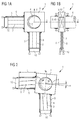
- FIG. 1 schematically shows components of a piezoelectric actuator 1 in front view ( 1A ) and side view ( 1B ).
- a piezoelectric actuator 1 has a drive ring 2 with a cylindrical bore 3, which encloses a rotatably mounted shaft 4.
- the drive ring 2 can be displaced in the plane perpendicular to the shaft axis (xy-plane) by means of two actuator units 5, 6 whose direction of action is orthogonal to one another and orthogonal to the shaft axis (z-axis).
- Each actuator unit comprises a solid-state actuator 7, 8, which is set by means of tensioning means 9 under compressive prestressing and mechanically rigidly coupled to the drive ring 2 and to a holding element 10.
- the holding elements 10 ensure a rigid connection (symbolized by the triangles) of the actuator units to z. B. a not shown stationary drive housing.
- the actuator units 5, 6 are excited to deflections in such a way that they set the drive ring 2 in a circular displacement movement about the shaft, so that the surface of the shaft encompassed by the drive ring 2 4 unrolls in the inner surface of the annular bore 3, and thereby the shaft 4 is rotated in rotation about its longitudinal axis (z-axis).
- An improvement of the power transmission between the corresponding surfaces of the drive ring 2 and shaft 4 leads to a higher maximum drive torque of the piezoelectric actuator drive 1 and z. B. by a suitable positive connection (eg., A toothing) can be achieved.
- FIG. 2 shows the piezoelectric actuator 1 in front view 1A , wherein at the shaft 4 now a torque M attacks. Torque loads acting on the shaft 4 are guided by the shaft 4 via the drive ring 2 and the actuator units 5, 6 to a stationary housing, not shown, and are received by the latter.
- the inner engine torque transmission path consisting of drive ring 2 and actuator units 5.6, has a high, but in no way infinitely high torsional stiffness, so that in the case of acting on the shaft 4 torque load of the drive ring 2 as shown slightly relative to the shaft axis (z-axis) or . is twisted relative to the housing (not shown).
- the resulting torsion angle ⁇ of the drive ring 2 (or rigidly connected to it elements) with respect to the housing is in very good Nährung directly proportional to the acting on the shaft 4 torque M.
- the self-adjusting torsion angle ⁇ remains to a good approximation unaffected by the driving Circular sliding movement of the drive ring 2.
- the drive ring 2 remains (except for the circular displacement for driving the shaft 4) fixed in space, ie, it does not rotate with the shaft 4 with.
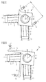
- FIG. 3 has the piezoelectric actuator 11 in addition to the components of FIGS. 1A, 1B and 2 two stationary (for example, in the housing, not shown attached) distance or distance measurement sensors 12 with a respective spatial resolution in the micron range.
- the measuring direction of the distance sensors 12 is parallel to each other and lies in the plane of movement of the drive ring (xy plane), so that each distance or distance changes between the respective sensor 12 and the drive ring 2 are detected in the measuring direction, so that in each case a component of the xy -Motion of the drive ring 2 (here the y-component) is measured.
- such sensors are 12 z. B. as capacitive displacement sensors or as eddy current sensors available.
- the mean value of the displacement signals from both distance sensors 12 represents the (time-dependent) component of the displacement of the drive ring 2, the difference of the displacement signals divided by their distance a provides a measure of the torsion angle ⁇ and thus of the momentarily acting torque M.
- Such measuring methods have a very high dynamics (typically with a cutoff frequency> 21 kHz or T ⁇ 50 ⁇ s).
- FIG. 4 shows a piezoelectric actuator 13 with a further sensor arrangement, in which the measuring directions of the sensors 12 lie in the xy plane and enclose an angle of, for example, 90 ° here.
- the advantage of this arrangement is that the movement of the drive ring 2 in the xy plane is completely detected.
- the disadvantage is the increased computational effort for the extraction of the drive ring torsion ⁇ from the measurement signals of the sensors 12.
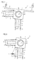
- FIG. 5 shows a Piezoaktorantrieb 14 with yet another sensor arrangement
- the now parallel aligned measuring directions of the sensors 12 are in the xy plane and are directed to side surfaces in the diagonal direction of the drive ring 2 and angled to the adjustment direction of the actuators 5.6.
- the measurement sensitivity with respect to the displacement of the drive ring 2 remains unchanged.
- FIG. 6 shows a piezoelectric actuator 15 with a further sensor arrangement analogous to that in FIG. 4 shown.
- two extension arms 16 are now rigidly fastened to the drive ring. From another point of view, the extension arms 16 are part of the drive ring 2.
- FIG. 7 shows a piezoelectric actuator 17 with a further sensor arrangement analogous to that in FIG. 3 shown, with extension arms 16 are now provided to increase the sensitivity on the drive ring 2 now.
- FIG. 8 shows a piezoelectric actuator 18 with yet another sensor arrangement with optical measurement of the torsion angle.
- At least one (eg in the housing, not shown mounted) fixed light source 19 directs a light beam L on a reflective side surface of the drive ring 2 and a connected to the drive ring 2 mirror 20, whereby the beam L is reflected back.
- a stationary, spatially resolving detector 21 detects the position of the reflected beam L 'or the position of the light spot on the drive ring 2, from which the torsion angle ⁇ and thus the applied torque M can be precisely determined. Due to the insignificance of the (drive) displacement movement based on the light pointer length exerts no or only a negligible disturbing influence on the Torsionsteil.
- a mirror 20 and reflector films can be used, whereby the optical requirements of the light source 19 can be kept low.
- Simple grating and pattern recognition methods can also be used. Simplest systems of this type are in mass production, z. As in computer mice, cost-effective, highly accurate and robust.
- FIG. 9 shows a Piezoaktorantrieb 22 with a particularly favorable arrangement of light source 19 and detector 21 in the xz plane, arranged at different z-coordinate values, with 9A in front view and FIG. 9B in side view.
- the advantage of this arrangement is that to a very good approximation, the flat drive ring movement in the xy plane only leads to a deflection of the reflected light beam in the z-direction, whereas a drive ring torsion ⁇ leads to an independent deflection of the light beam in the y-direction.
- the drive ring torsion can thus be determined precisely.
- the sensitivity of the measuring arrangement can also be increased here.
- reflective surfaces may be present on extension arms of the drive ring 2 or provided holes in the drive ring 2, which are completed in a mirror.
- the torsion of the drive ring is independent of the operating state of the piezo actuator drive measurable. It can be measured both when the piezoelectric actuator drive is stationary and when the piezoelectric actuator drive is in operation. Furthermore, in contrast to the load measuring methods cited under point 2, the measuring principle is long-term stable using the electrical signals (charges) generated load-dependently in the piezoelectric actuators for long-term stability.
- the present invention is not limited to the embodiments shown.
- the measuring device can also have more than two sensors.
- the sensors can be arranged at any suitable angles to each other.
Landscapes
- General Electrical Machinery Utilizing Piezoelectricity, Electrostriction Or Magnetostriction (AREA)
Abstract
Description
Die Erfindung betrifft einen festkörperaktorischer Antrieb, insbesondere einen Piezoaktorantrieb ("Piezoelectric Actuator Drive"; PAD), und ein Verfahren zum Bestimmen eines Torsionswinkels eines festkörperaktorischen Antriebs.The invention relates to a solid-state actuator, in particular a piezoelectric actuator drive ("PAD"), and a method for determining a torsion angle of a solid-state actuator.
Beispielsweise offenbaren
Zur Steuerung des Piezoaktorantriebs kommt einer Messung einer an der Motorwelle angreifenden Drehmomentlast besondere Bedeutung zu, da daraus vielerlei übergeordnete 'lastadaptive' Systemfunktionen für den Antrieb abgeleitet werden können, wie z. B.: der Antrieb stoppt bei Erreichen eines vorgegebenen Schwellwerts; der Antrieb reversiert beim Erreichen eines bestimmten Schwellwertes; oder der Antrieb beschleunigt oder verzögert im Drehmomentoptimum unabhängig vom an der Welle angekoppelten Massenträgheitsmoment.
Es ist eine Aufgabe der vorliegenden Erfindung, eine Möglichkeit zur betriebszustandsunabhängigen Messung einer an der Motorwelle angreifenden Drehmomentlast bereitzustellen, die zugleich langzeitstabil ist.It is an object of the present invention to provide a possibility for operating state independent measurement of a torque load acting on the motor shaft, which is at the same time long-term stable.
Diese Aufgabe wird durch einen festkörperaktorischen Antrieb, insbesondere Piezoaktorantrieb, nach Anspruch 1 und ein Verfahren nach Anspruch 8 gelöst.This object is achieved by a solid-state actuator, in particular piezoelectric actuator, according to claim 1 and a method according to
Der festkörperaktorische Antrieb, insbesondere Piezoaktorantrieb, misst einen Torsionswinkel des Antriebsrings direkt (d. h. am Antriebsring oder einem damit fest verbundenen Element), und nicht indirekt über ein Spannungssignal eines Aktors. Der festkörperaktorische Antrieb weist einen durch Festkörperaktoren (z. B. Piezoaktor, elektrostriktiver Aktor, magnetostriktiver Aktor usw.) angetriebenen Antriebsring auf, wobei der Antriebsring eine Aussparung aufweist, in der eine mittels des Antriebsrings drehbare Welle kraftschlüssig angeordnet ist. Ferner weist der festkörperaktorische Antrieb eine Messvorrichtung zur Bestimmung eines Torsionswinkels des Antriebsrings - typischerweise bezüglich einer Drehachse der Welle - mit mindestens einem berührungslosen Sensor auf. Die Messrichtung des mindestens einen Sensors ist somit auf einen Messbereich auf dem Antriebsring gerichtet.The solid-state actuator drive, in particular a piezo actuator drive, measures a torsion angle of the drive ring directly (i.e., on the drive ring or an element fixedly connected thereto), and not indirectly via a voltage signal of an actuator. The solid-state actuator drive has a drive ring driven by solid-state actuators (eg, piezoactuator, electrostrictive actuator, magnetostrictive actuator, etc.), the drive ring having a recess in which a shaft rotatable by means of the drive ring is frictionally arranged. Furthermore, the solid-state actuator drive has a measuring device for determining a torsion angle of the drive ring-typically with respect to an axis of rotation of the shaft-with at least one non-contact sensor. The measuring direction of the at least one sensor is thus directed to a measuring range on the drive ring.
Dadurch kann die Messung des Torsionswinkels, und daraus des Drehmoments, unabhängig vom Betriebszustand des Piezoaktorantriebs (ruhend / in Betrieb, o.ä.) durchgeführt werden. Zudem ist die direkte Torsionswinkel- und Drehmomentmessung im Gegensatz zu den Lastmeßmethoden unter Nutzung der in den piezoelektrischen Aktoren lastabhängig generierten elektrischen Signale (Ladungen) langzeitstabil.Thereby, the measurement of the torsion angle, and therefrom of the torque, regardless of the operating state of the piezo actuator drive (dormant / in operation, or similar) can be performed. In addition, the direct Torsionswinkel- and torque measurement in contrast to the Lastmeßmethoden using the load-dependent generated in the piezoelectric actuators electrical signals (charges) long-term stability.
Vorzugsweise kann die Messvorrichtung ferner aus dem Torsionswinkel ein Drehmoment bzw. eine Drehmomentlast an der Welle bestimmen.Preferably, the measuring device may further determine a torque or a torque load on the shaft from the torsion angle.
Vorzugweise umfasst der mindestens eine berührungslose Sensor mindestens zwei Weg- bzw. Abstandssensoren, insbesondere kapazitive Wegsensoren oder Wirbelstromsensoren. Die Weg- bzw. Abstandssensoren können einen Abstand zum Antriebsring und / oder eine Abstandsänderung zum Antriebsring erfassen.Preferably, the at least one non-contact sensor comprises at least two displacement or distance sensors, in particular capacitive displacement sensors or eddy current sensors. The displacement and distance sensors can detect a distance to the drive ring and / or a change in distance to the drive ring.
Alternativ umfasst der mindestens eine berührungslose Sensor einen optischen Sensor, der eine Lichtquelle und einen von der Lichtquelle definiert beabstandeten Lichtdetektor umfasst, wobei der Lichtdetektor eine Positionsänderung eines von der Lichtquelle ausgesandten Lichtstrahls am Antriebsring abtastet.Alternatively, the at least one non-contact sensor comprises an optical sensor which comprises a light source and a light detector spaced from the light source, wherein the light detector scans a change in position of a light beam emitted from the light source on the drive ring.
Bevorzugt weist der Antriebsring Verlängerungselemente, insbesondere Verlängerungsarme, auf, an denen ein Sensorsignal abtastbar ist.The drive ring preferably has extension elements, in particular extension arms, on which a sensor signal can be scanned.
Die Verlängerungsarme können innerhalb eines Antriebsgehäuses angeordnet sein. Alternativ können die Verlängerungsarme aus einem Antriebsgehäuse herausgeführt sein, wobei die Messvorrichtung sowie ein Abtastgebiet für das Sensorsignal am jeweiligen Verlängerungsarm außerhalb des Antriebsgehäuses angeordnet sind.The extension arms may be disposed within a drive housing. Alternatively, the extension arms can be guided out of a drive housing, wherein the measuring device and a scanning region for the sensor signal are arranged on the respective extension arm outside the drive housing.
Das Verfahren dient zum Bestimmen eines Torsionswinkels eines festkörperaktorischen Antriebs - insbesondere wie oben beschrieben - mit mindestens einem durch Festkörper-Stellantriebe (Festkörperaktoren) angetriebenen Antriebsring, wobei der Antriebsring eine Aussparung aufweist, in der eine mittels des Antriebsrings drehbare Welle kraftschlüssig angeordnet ist, wobei der Torsionswinkel des Antriebsrings mittels mindestens eines Sensors berührungslos bestimmt wird.The method is used to determine a torsion angle of a solid-state actuator - in particular as described above - with at least one driven by solid actuators (solid state actuators) drive ring, wherein the drive ring has a recess in which a shaft rotatable by means of the drive ring is arranged frictionally, wherein the Torsion angle of the drive ring is determined without contact by means of at least one sensor.
Vorzugsweise wird eine Drehmomentlast an der Welle aus der Bestimmung des Torsionswinkels abgeleitet.Preferably, a torque load on the shaft is derived from the determination of the torsion angle.
Vorzugsweise wird der Torsionswinkel durch jeweiliges Abtasten einer Wegänderung des Antriebsrings oder damit fest verbundener Elemente bestimmt, insbesondere mittels kapazitiver Wegsensoren oder Wirbelstromsensoren.Preferably, the torsion angle is determined by respective scanning a path change of the drive ring or thus firmly connected elements, in particular by means of capacitive displacement sensors or eddy current sensors.
Vorzugsweise wird der Torsionswinkel durch jeweiliges Abtasten einer Positionsänderung eines Lichtflecks am Antriebsring bestimmt.Preferably, the torsion angle is determined by respectively sensing a change in position of a light spot on the drive ring.
Vorzugsweise werden Sensorsignale an Verlängerungsarmen des Antriebsrings abgetastet.Preferably, sensor signals are sampled on extension arms of the drive ring.
Der festkörperaktorische Antrieb ist aufgrund der guten Handhabbarkeit, der guten Betriebseigenschaften und des geringen Preises vorzugsweise ein Piezoaktor. Im Folgenden wird, wo nicht explizit anders ausgeführt, zur vereinfachten Beschreibung der Antrieb mit einem Piezoaktor als Festkörperaktor genauer ausgeführt. Jedoch ist diese Festlegung nicht dazu gedacht, den Umfang der Erfindung zu beschränken.The Festkörperaktorische drive is preferably a piezoelectric actuator due to the good handling, good operating characteristics and low price. In the following, where not explicitly stated otherwise, the drive with a piezoelectric actuator as a solid-state actuator is more precisely executed for a simplified description. However, this definition is not intended to limit the scope of the invention.
Im Folgenden wird ein Piezoaktorantrieb anhand von Ausführungsbeispielen schematisch genauer beschrieben. Dabei werden gleiche Komponenten mit gleichen Bezugsziffern bezeichnet.
- FIG 1A
- zeigt einen grundsätzlichen Aufbau eines Piezoaktorantriebs in Vorderansicht;
- FIG 1B
- zeigt den Piezoaktorantrieb aus
FIG 1A in Seitenansicht; - FIG 2
- den Piezoaktorantrieb aus
FIG 1A in tordiertem Zustand in Seitenansicht; - FIG 3
- zeigt den Piezoaktorantrieb aus
FIG 2 mit einer Messvorrichtung zur Bestimmung eines Torsionswinkels gemäß einer ersten Ausführungsform; - FIG 4
- zeigt den Piezoaktorantrieb aus
FIG 2 mit einer Messvorrichtung zur Bestimmung eines Torsionswinkels gemäß einer zweiten Ausführungsform; - FIG 5
- zeigt den Piezoaktorantrieb aus
FIG 2 mit einer Messvorrichtung zur Bestimmung eines Torsionswinkels gemäß einer dritten Ausführungsform; - FIG 6
- zeigt den Piezoaktorantrieb aus
FIG 2 mit einer Messvorrichtung zur Bestimmung eines Torsionswinkels gemäß einer vierten Ausführungsform; - FIG 7
- zeigt den Piezoaktorantrieb aus
FIG 2 mit einer Messvorrichtung zur Bestimmung eines Torsionswinkels gemäß einer fünften Ausführungsform; - FIG 8
- zeigt den Piezoaktorantrieb aus
FIG 2 mit einer Messvorrichtung zur Bestimmung eines Torsionswinkels gemäß einer fünften Ausführungsform; - FIG 9A
- zeigt den Piezoaktorantrieb aus
FIG 2 mit einer Messvorrichtung zur Bestimmung eines Torsionswinkels gemäß einer fünften Ausführungsform in Vorderansicht; - FIG 9B
- zeigt den Piezoaktorantrieb aus
FIG 9A in Seitenansicht.
- 1A
- shows a basic structure of a piezoelectric actuator in front view;
- 1B
- shows the piezo actuator drive
1A in side view; - FIG. 2
- the piezo actuator drive off
1A in a twisted state in side view; - FIG. 3
- shows the piezo actuator drive
FIG. 2 with a measuring device for determining a torsion angle according to a first embodiment; - FIG. 4
- shows the piezo actuator drive
FIG. 2 with a measuring device for determining a torsion angle according to a second embodiment; - FIG. 5
- shows the piezo actuator drive
FIG. 2 with a measuring device for determining a torsion angle according to a third embodiment; - FIG. 6
- shows the piezo actuator drive
FIG. 2 with a measuring device for determining a torsion angle according to a fourth embodiment; - FIG. 7
- shows the piezo actuator drive
FIG. 2 with a measuring device for determining a torsion angle according to a fifth embodiment; - FIG. 8
- shows the piezo actuator drive
FIG. 2 with a measuring device for determining a torsion angle according to a fifth embodiment; - 9A
- shows the piezo actuator drive
FIG. 2 with a measuring device for determining a torsion angle according to a fifth embodiment in front view; - FIG. 9B
- shows the piezo actuator drive
9A in side view.
Unter Anwendung der Eulerschen' Biegetheorie auf die hauptsächlich zur Ringtorsion beitragenden Festkörperaktoren 5,6 und unter Vernachlässigung der als biegeweich anzunehmenden Spannmittel 9 berechnet sich der unter der Drehmomentlast M einstellende Torsionswinkel ϕ zu: 
- 1:
Länge eines Festkörperaktors - r:
- Abstand zwischen Mittelpunkt des Antriebsrings 2 und Auflagefläche eines Festkörperaktors 7,8
- M:
- Drehmoment (last)
- E:
- E-Modul des Aktormaterials
- I:
- Flächenträgheitsmoment des Aktorquerschnitts
- 1:
- Length of a solid-
state actuator - r:
- Distance between the center of the
drive ring 2 and bearing surface of a solid-state actuator - M:
- Torque (last)
- e:
- E-modulus of the actuator material
- I:
- Area moment of inertia of the actuator cross-section
In
Es sind auch andere Sensoranordnungen anwendbar, von denen einige in den folgenden Abbildungen gezeigt sind.Other sensor arrangements are also applicable, some of which are shown in the following figures.
Bei den obigen Messprinzipien ist die Torsion des Antriebsrings unabhängig vom Betriebszustand des Piezoaktorantriebs messbar. Sie ist sowohl bei ruhendem Piezoaktorantrieb als auch bei im Betrieb befindlichen Piezoaktorantrieb messbar. Ferner ist das Messprinzip langzeitstabil im Gegensatz zu den unter Punkt 2 zitierten Lastmeßmethoden unter Nutzung der in den piezoelektrischen Aktoren lastabhängig generierten elektrischen Signale (Ladungen) langzeitstabil.In the above measuring principles, the torsion of the drive ring is independent of the operating state of the piezo actuator drive measurable. It can be measured both when the piezoelectric actuator drive is stationary and when the piezoelectric actuator drive is in operation. Furthermore, in contrast to the load measuring methods cited under
Selbstverständlich ist die vorliegende Erfindung nicht auf die gezeigten Ausführungsformen beschränkt. So kann die Messvorrichtung auch mehr als zwei Sensoren aufweisen. Auch können die Sensoren unter beliebigen geeigneten Winkeln zueinander angeordnet sein.Of course, the present invention is not limited to the embodiments shown. Thus, the measuring device can also have more than two sensors. Also, the sensors can be arranged at any suitable angles to each other.
Claims (12)
aufweisend eine Messvorrichtung zur Bestimmung eines Torsionswinkels (ϕ) des Antriebsrings (2) mit mindestens einem berührungslosen Sensor (12; 19,21).Solid-state actuator drive, in particular a piezo actuator drive (11; 13; 14; 15; 17; 18; 22), with at least one drive ring (2) driven by piezoactuators (7, 8), the drive ring (2) having a recess (3), in which a shaft (4) rotatable by means of the drive ring (2) is non-positively arranged,
comprising a measuring device for determining a torsion angle (φ) of the drive ring (2) with at least one non-contact sensor (12, 19, 21).
wobei der Torsionswinkel (ϕ) des Antriebsrings (2) mittels mindestens eines Sensors (12; 19,21) berührungslos bestimmt wird.Method for determining a torsion angle (φ) of a solid-state actuator, in particular a piezo actuator drive (11; 13; 14; 17; 18; 22), with at least one drive ring (2) driven by piezoactuators (7,8), wherein the drive ring (2) a recess (3) in which a by means of the drive ring (2) rotatable shaft (4) is arranged non-positively,
wherein the torsion angle (φ) of the drive ring (2) by means of at least one sensor (12; 19,21) is determined without contact.
Applications Claiming Priority (1)
| Application Number | Priority Date | Filing Date | Title |
|---|---|---|---|
| DE200710028642 DE102007028642A1 (en) | 2007-06-21 | 2007-06-21 | Solid state actuator drive |
Publications (1)
| Publication Number | Publication Date |
|---|---|
| EP2053671A2 true EP2053671A2 (en) | 2009-04-29 |
Family
ID=39765219
Family Applications (1)
| Application Number | Title | Priority Date | Filing Date |
|---|---|---|---|
| EP20080104219 Withdrawn EP2053671A2 (en) | 2007-06-21 | 2008-06-02 | Solid state actuator driving device |
Country Status (2)
| Country | Link |
|---|---|
| EP (1) | EP2053671A2 (en) |
| DE (1) | DE102007028642A1 (en) |
Families Citing this family (2)
| Publication number | Priority date | Publication date | Assignee | Title |
|---|---|---|---|---|
| CN105634328B (en) * | 2016-02-26 | 2018-01-02 | 南京航空航天大学 | Rotary type travelling wave piezoelectric actuator and its control method |
| EP3301730B1 (en) * | 2016-09-29 | 2018-12-26 | Airbus Defence and Space GmbH | Energy converter device |
Citations (3)
| Publication number | Priority date | Publication date | Assignee | Title |
|---|---|---|---|---|
| EP1098429B1 (en) | 1999-11-03 | 2004-10-06 | Siemens Aktiengesellschaft | Electromechanical motor |
| DE102005024317A1 (en) | 2005-05-27 | 2006-11-30 | Siemens Ag | Solid state actuator drive device with a rotatable shaft |
| DE102005028482A1 (en) | 2005-06-20 | 2006-12-28 | Siemens Ag | Piezoelectric ring motor e.g. electromechanical motor, adjusting method, involves calculating offset value from voltage values that are recorded based on signal characteristics evaluation when actuators are actuated, during motor operation |
Family Cites Families (8)
| Publication number | Priority date | Publication date | Assignee | Title |
|---|---|---|---|---|
| DE3344385A1 (en) * | 1983-12-08 | 1985-06-20 | Robert Bosch Gmbh, 7000 Stuttgart | TOUCH-FREE MEASURING DEVICE FOR TORQUE AND / OR TURNING ANGLE |
| JPS62293978A (en) * | 1986-06-11 | 1987-12-21 | Canon Inc | Rotating actuator |
| DE4439230C2 (en) * | 1994-11-03 | 1996-08-14 | Ingenieure Prof Sturm & Partne | Device and method for determining the condition of fittings |
| DE29822319U1 (en) * | 1998-12-15 | 1999-03-18 | Kipfelsberger Albert | Torque measuring device as a static / dynamic torque measuring simulator |
| DE10117724C2 (en) * | 2001-04-09 | 2003-03-27 | Methode Electronics Malta Ltd | Device for determining the torque on a rotatable metallic shaft |
| DE10247321B3 (en) * | 2002-10-10 | 2004-02-12 | Robert Bosch Gmbh | Sensing rotary motion and torque from phase measurements and computerized linear transformation, adopts iterative approximation technique |
| DE102005022355A1 (en) * | 2005-05-13 | 2006-11-30 | Siemens Ag | Electromechanical control drive e.g. piezoelectric control drive, for e.g. automotive engineering field, has actuators positioned on x`-z`-plane and/or y`-z`-plane and actuator units positioned together in right-angled coordinate system |
| DE102005036822A1 (en) | 2005-08-04 | 2007-02-15 | Siemens Ag | Electromechanical motor |
-
2007
- 2007-06-21 DE DE200710028642 patent/DE102007028642A1/en not_active Withdrawn
-
2008
- 2008-06-02 EP EP20080104219 patent/EP2053671A2/en not_active Withdrawn
Patent Citations (3)
| Publication number | Priority date | Publication date | Assignee | Title |
|---|---|---|---|---|
| EP1098429B1 (en) | 1999-11-03 | 2004-10-06 | Siemens Aktiengesellschaft | Electromechanical motor |
| DE102005024317A1 (en) | 2005-05-27 | 2006-11-30 | Siemens Ag | Solid state actuator drive device with a rotatable shaft |
| DE102005028482A1 (en) | 2005-06-20 | 2006-12-28 | Siemens Ag | Piezoelectric ring motor e.g. electromechanical motor, adjusting method, involves calculating offset value from voltage values that are recorded based on signal characteristics evaluation when actuators are actuated, during motor operation |
Also Published As
| Publication number | Publication date |
|---|---|
| DE102007028642A1 (en) | 2008-12-24 |
Similar Documents
| Publication | Publication Date | Title |
|---|---|---|
| DE102005003684B4 (en) | Fine adjustment mechanism for scanning probe microscopy | |
| WO2013092068A1 (en) | Device having a measuring apparatus for measuring forces and/or loads | |
| EP2363685A1 (en) | Positioning device with confocal Fabry-Perot interferometer | |
| EP2473818B1 (en) | Device for measuring and/or detecting distances and distance changes and device for measuring and/or detecting mechanical loads | |
| EP2053671A2 (en) | Solid state actuator driving device | |
| DE102009028343A1 (en) | Sensor element and method for operating a sensor element | |
| EP1903326B1 (en) | Device for determining torsional moments in the submicron Newton metre range | |
| EP2435354B1 (en) | Micromechanical component and method for the production thereof | |
| DE102011000054B4 (en) | torsion sensor | |
| WO2002095333A1 (en) | Method for non-contact linear position measurement | |
| DE102006060584B4 (en) | Method and device for measuring displacements and / or a geometry of microstructures | |
| DE3016782A1 (en) | Pressure three=dimensional probe for workpiece measurement - has sensitive elements in sensor mounting which are movable w.r.t. base | |
| DE3501288A1 (en) | DEVICE FOR NON-DESTRUCTIVE, ABSOLUTE MEASUREMENT OF PROPERTIES OF SOLID SUBSTANCES THAT CAN BE DERIVED FROM THE INTRUSION OF A TESTING BODY INTO THE SUBSTANCE | |
| EP3913349A1 (en) | Method for determining the load on a drive shaft | |
| EP1174680A2 (en) | Device for varying the path length of an electromagnetic wave | |
| DE10161541B4 (en) | Sensor arrangement and functional unit with sensor arrangement | |
| DE102011104228B4 (en) | Device for measuring length and use of the device for determining physical properties of test objects | |
| EP2199769A2 (en) | Force measuring device | |
| AT402977B (en) | ARRANGEMENT FOR DYNAMIC FORCE-TRAVEL MEASUREMENT | |
| DE19947370C2 (en) | Displacement sensor | |
| EP1999843B1 (en) | Method for load detection on a solid state actuator/motor device | |
| EP1480045A1 (en) | Scanner | |
| EP2143153B1 (en) | Solid-state actuator, particularly piezoelectric, drive and method for the acquisition of sensor data from a solid-state actuator, particularly piezoelectric, drive | |
| DE19753554A1 (en) | Force sensor, e.g. for electronic braking-control in motor vehicle | |
| EP2975357A2 (en) | Device comprising a scanning unit and an assembly aid and method for assembling the scanning unit |
Legal Events
| Date | Code | Title | Description |
|---|---|---|---|
| PUAI | Public reference made under article 153(3) epc to a published international application that has entered the european phase |
Free format text: ORIGINAL CODE: 0009012 |
|
| PUAI | Public reference made under article 153(3) epc to a published international application that has entered the european phase |
Free format text: ORIGINAL CODE: 0009012 |
|
| AK | Designated contracting states |
Kind code of ref document: A2 Designated state(s): AT BE BG CH CY CZ DE DK EE ES FI FR GB GR HR HU IE IS IT LI LT LU LV MC MT NL NO PL PT RO SE SI SK TR |
|
| AX | Request for extension of the european patent |
Extension state: AL BA MK RS |
|
| STAA | Information on the status of an ep patent application or granted ep patent |
Free format text: STATUS: THE APPLICATION HAS BEEN WITHDRAWN |
|
| 18W | Application withdrawn |
Effective date: 20100914 |