EP2473818B1 - Device for measuring and/or detecting distances and distance changes and device for measuring and/or detecting mechanical loads - Google Patents
Device for measuring and/or detecting distances and distance changes and device for measuring and/or detecting mechanical loads Download PDFInfo
- Publication number
- EP2473818B1 EP2473818B1 EP10752312.8A EP10752312A EP2473818B1 EP 2473818 B1 EP2473818 B1 EP 2473818B1 EP 10752312 A EP10752312 A EP 10752312A EP 2473818 B1 EP2473818 B1 EP 2473818B1
- Authority
- EP
- European Patent Office
- Prior art keywords
- length
- change
- distance
- component
- changes
- Prior art date
- Legal status (The legal status is an assumption and is not a legal conclusion. Google has not performed a legal analysis and makes no representation as to the accuracy of the status listed.)
- Not-in-force
Links
Images


Classifications
-
- G—PHYSICS
- G01—MEASURING; TESTING
- G01B—MEASURING LENGTH, THICKNESS OR SIMILAR LINEAR DIMENSIONS; MEASURING ANGLES; MEASURING AREAS; MEASURING IRREGULARITIES OF SURFACES OR CONTOURS
- G01B21/00—Measuring arrangements or details thereof, where the measuring technique is not covered by the other groups of this subclass, unspecified or not relevant
- G01B21/32—Measuring arrangements or details thereof, where the measuring technique is not covered by the other groups of this subclass, unspecified or not relevant for measuring the deformation in a solid
-
- F—MECHANICAL ENGINEERING; LIGHTING; HEATING; WEAPONS; BLASTING
- F03—MACHINES OR ENGINES FOR LIQUIDS; WIND, SPRING, OR WEIGHT MOTORS; PRODUCING MECHANICAL POWER OR A REACTIVE PROPULSIVE THRUST, NOT OTHERWISE PROVIDED FOR
- F03D—WIND MOTORS
- F03D17/00—Monitoring or testing of wind motors, e.g. diagnostics
Definitions
- the invention relates to devices for measuring and / or detection of distances and distance changes as well as devices for measuring and / or detection of mechanical loads.
- these changes can be assigned to the respective load and are therefore also a measure of this load on the body.
- a monitoring of the load thus a load monitoring, can thus be carried out by detecting or measuring the external dimensions of the respective body.
- Another object of the invention is to provide a device and a method with which mechanical loads of components can be detected and / or measured.
- a device according to the invention for detecting and / or measuring distances and / or distance changes comprises a device for the transmission of distance changes, as well as at least one sensor for detecting and / or measuring distances and / or distance changes.
- a basic idea of the invention is to reinforce loads, which can be measured in the form of distance changes, by mechanical translation structures in such a way that a more accurate measurement can be achieved.
- the reinforced i. Increased distances to be measured, a higher accuracy, since a given measurement error has a small effect at larger distances to be measured.
- the structure which converts the path change resulting from the load of the component with a corresponding mechanical structure into a distance measurement which is larger by factors and which physically detects this distance change can advantageously comprise joints, in particular solid joints.
- the means for translating distance changes comprises an assembly with joints, preferably with solid joints.
- the joints essentially define a transmission ratio between the path change sensed and / or measured by the sensor and the path change applied to the device.
- the gear ratio is non-linear.
- the transmission ratio can be linearly approximated in a simple manner.
- the measured value is linearly converted into a distance value for this purpose.
- a non-linear transmission ratio can however be taken into account with a correspondingly non-linear characteristic.
- the measured values are converted into distance values with a non-linear characteristic.
- the device for the translation of distance changes symmetric, preferably mirror-symmetrically arranged arms and joints, wherein the sensor is advantageously arranged at a distance change arranged on one arm relative to the other arm.
- a further embodiment of the device provides that the device for the translation of distance changes comprises sheets which, preferably milled or eroded, have recesses which in turn define solid joints.
- Another embodiment of the invention is a device for detecting and / or measuring mechanical loads. This comprises one or more devices for detecting and / or measuring distances and / or distance changes as described above. The load of a component can then be derived or calculated from the detected and / or measured distance change of the component.
- the senor is arranged on a solid-body joint arrangement.
- the sensor may be part of a solid state hinge assembly.
- a particularly preferred embodiment of the invention provides that the device for detecting and / or measuring and / or measuring distances and / or distance changes in the form of changes in length of a component under load, a device for detecting and / or measuring firmly connected to the component the length changes by means of mechanical translation structures for translation and amplification of actual changes in length includes.
- it has at least one sensor for detecting and / or measuring the translated changes in length and a recording and / or Evaluation device for recording and / or evaluation of the translated length changes.
- the mechanical translation structures comprise solid-state hinges which on the one hand permit the translation of very small changes in length, for example in the nm or ⁇ m range, and on the other hand are also very wear-resistant.
- the mechanical translation structures comprise solid-body joint arrangements, which consist of or comprise a plurality of solid-state joints.
- Such a solid-state joint arrangement advantageously allows a design of the deflection by the translation.
- the solid-state joint arrangements may each have one or more solid joints, for example in the form of recesses formed in a strip or strip of material, preferably in a sheet-metal strip.
- the recesses then open preferably to one or the other longitudinal edge of the sheet metal strip and deform elastically under load of the component.
- other materials are conceivable, from which the solid-state joint arrangements can be made. These are known to the person skilled in the art.
- the means for detecting and / or measuring the change in length comprises two fixedly connected to the component blocks or mounting blocks, wherein the Festismegelenkan extract in turn are firmly connected to the mounting blocks. This creates a frictional connection between the device and the component, which allows an exact or accurate determination or measurement of the deformation of the component.
- a device for detecting and / or measuring distances and / or distance changes can be used for detecting and / or measuring a mechanical load acting on the component, in particular in the form of tension and / or Compressive stresses used.
- the detected and / or measured distance changes are set in relation to the applied load.
- the term measurement is intended to reflect the measurement of the named quantity, thus either a distance, a distance change or a load or a load change.
- detection refers to the measurement or detection of at least one value by the respective sensor, such as a limit value.
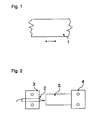
- FIG. 1 shows a typical measurement task, as it can occur when measuring mechanical loads or during load monitoring.
- a body 1 is compressed or stretched by the application of a force and thus by the action of a load by a specific value, which is shown by way of example under the body 1 between two arrows as a route.
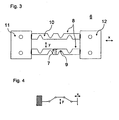
- FIG. 3 shows a preferred embodiment of a device 1 according to the invention for the detection and / or measurement of distances and / or distance changes, or a device for detecting and / or measuring mechanical loads.
- This device for detecting and / or measuring distances and / or distance changes, comprises a sensor 7 for detecting and / or measuring distances and / or distance changes, and a device for translating distance changes 8.
- This joint is a recess or constriction within a sheet or solid 10.
- the transmission ratio may be at least partially non-linear, for example, if plastic deformations, in particular of the sheets or solid 10, which include the joints, occur or the length of the respective arms between the solid joints 9 generates such a ratio.
- the sensor 7 is arranged on an arm and is at a distance change in the direction x relative to the other arm in Direction y moves the gear ratio accordingly.
- the sheets are arranged between two mounting blocks 11, 12 and laser welded to them.
- the sheets 10 and the mounting blocks 11, 12 are made by milling of solid material.
- the invention also includes a device for detecting and / or measuring distances and / or distance changes 6, with more than one device as described above.
- a device for detecting and / or measuring distances and / or distance changes 6 with more than one device as described above.
- two, three or more of these devices 6 may be provided to be able to detect loads and / or distance changes acting in different directions.
- a device according to the invention for detecting and / or measuring mechanical loads comprises one or more devices for detecting and / or measuring distances and / or distance changes 6, as described above.
- the translation structure to dimension essentially arbitrary, there is the translation structure and necessary for the physical measurement principles facilities in a sensor.
- the senor contains a pull-down device or its own load device in order to determine a mechanical deformation (defect of the sensor).
- a safety structure to protect the sensor from overloading. An alarm output can then be activated in case of overload.
- a memory function of measurements is also helpful for many applications, in particular for the calibration or scaling of the respective measured variables.
- An intelligent embodiment of the invention also has a device for self-selection of measuring ranges over different translation structures (preferably with limiting structures due to stress destruction).
- a particularly suitable field of use for the device according to the invention is also the measurement of dynamic loads on components.
- the device according to the invention can also be used to detect mechanical loads on rotating parts of a wind turbine.
- the invention also relates to a wind turbine with an inventive device for detecting and / or measuring distances and / or distance changes in the form of changes in length of a component under load, wherein the device according to the invention is attached to a rotating part of the wind turbine, as well as the use of an inventive Device for detecting and / or measuring distances and / or distance changes in the form of changes in length of a component under load for the measurement of mechanical loads on rotating elements of wind turbines.
- the distance changes can be induced by any mechanical load Deformations of the rotating element are caused.
- rotating parts are in particular the rotor blades, the rotor hub, the connection of the rotor blades on the rotor hub and the rotor shaft into consideration.
- high mechanical loads occur over the forces exerted by the rotor blades with a long lever arm.
- the use of the device according to the invention for measuring the mechanical load of the rotor shaft of a wind turbine is accordingly provided.
- FIG. 5A a further device 61 according to the invention for detecting and / or measuring distances and / or distance changes on a rotor blade 29 is shown.
- each of the devices 6 have its own self-sufficient generator 43 and / or a wireless transmission device 44.
- Fig. 6 shows a self-sufficient generator 43 comprising a piezoelectric transducer 431.
- the piezoelectric transducer 431 comprises a piezoelectric element 4310, for example a piezoceramic.
- the piezoelectric element 4310 is provided with two electrodes 4311, 4312 for tapping the piezoelectric voltage.
- the transducer may be mounted inside the rotor blade, for example, as shown, in a spar 54.
- Fig. 7 shows an example of an electromagnetic wave converter 432.
- This converter 432 has an antenna 4320.
- the circuit 430 here comprises amplifier circuit for amplifying the radio or radio waves received via the antenna 4320 and a rectifier circuit.
- the rotary generator can in this way dynamoelectrically generate electrical energy that is conditioned by the circuit 430.
- the principle of this generator assumes that the centrifugal force at the installation site does not exceed gravity. If this is the case, for example, at the wing tips, but also dynamoelectric generators can be used, which draw energy either from vibration via a movable inertia element or also via an example, springy inertia element kinetic energy from the direction and size by the action of gravity generate and convert changing force vector.
- the principle of self-sufficient energy supply of a device for measuring loads due to changes in length in or on rotating parts of a wind turbine can also with other sensor types, as the Inductive sensor according to the invention, or the device 6 are realized. It offers the particular advantage that in connection with a wireless transmission device any wiring with external, not co-rotating facilities can be omitted.
Description
Die Erfindung betrifft Vorrichtungen zur Messung und/oder Erfassung von Distanzen und Distanzänderungen sowie Vorrichtungen zur Messung und/oder Erfassung von mechanischen Belastungen.The invention relates to devices for measuring and / or detection of distances and distance changes as well as devices for measuring and / or detection of mechanical loads.
Aus dem Stand der Technik sind Dehnmesstransformatoren bekannt, welche Dehnungsmessstreifen, DMS, umfassen, die jedoch in vielen Fällen die für manche Anwendungen erwünschte Genauigkeit nicht erreichen können. Für höhere Genauigkeiten können auch auf Dehnmeßstreifen basierende Dehntransformatoren verwendet werden. Diese sind aber wiederum deutlich teurer.Dehnmesstransformatoren are known from the prior art, which strain gages, DMS include, but in many cases can not achieve the desired accuracy for some applications. For higher accuracies strain gauges based on strain gauges can be used. These are, however, significantly more expensive.
Wird ein Körper mechanisch belastet, kommt es in der Regel, abhängig von den Belastungen zu mehr oder weniger starken Änderungen von dessen Form oder äußeren Abmessungen.If a body is mechanically stressed, it usually comes, depending on the loads to more or less strong changes of its shape or external dimensions.
In vielen Fällen können diese Änderungen der jeweiligen Belastung zugeordnet werden und sind somit auch ein Maß für diese Belastung des Körpers. Eine Überwachung der Belastung, somit ein Belastungsmonitoring, kann folglich durch Erfassung oder Messung der äußeren Abmessungen des jeweiligen Körpers durchgeführt werden.In many cases, these changes can be assigned to the respective load and are therefore also a measure of this load on the body. A monitoring of the load, thus a load monitoring, can thus be carried out by detecting or measuring the external dimensions of the respective body.
Eine Aufgabe der Erfindung liegt somit darin, die Messgenauigkeit insbesondere von Vorrichtungen zur Erfassung und/oder Messung von Distanzen und/oder Distanzänderungen sowie ein Verfahren zur Erfassung und/oder Messung von Distanzen und/oder Distanzänderungen bereitzustellen, die eine höhere Messgenauigkeit ermöglichen. Eine weitere Aufgabe der Erfindung besteht in der Bereitstellung einer Vorrichtung und eines Verfahrens mit welchen mechanische Belastungen von Bauteilen erfasst und/oder gemessen werden können.It is therefore an object of the invention to provide the measuring accuracy, in particular of devices for detecting and / or measuring distances and / or distance changes, as well as a method for detecting and / or measuring distances and / or distance changes, which allow a higher accuracy of measurement. Another object of the invention is to provide a device and a method with which mechanical loads of components can be detected and / or measured.
Die Aufgabe wird mittels einer Vorrichtung und eines Verfahrens mit den Merkmalen der unabhängigen Ansprüche 1 und 9 gelöst. Demgemäß umfasst eine erfindungsgemäße Vorrichtung zur Erfassung und/oder Messung von Distanzen und/oder Distanzänderungen eine Einrichtung zur Übersetzung von Distanzänderungen, sowie zumindest einen Sensor zur Erfassung und/oder Messung von Distanzen und/oder Distanzänderungen.The object is achieved by means of a device and a method having the features of the
Eine Grundidee der Erfindung liegt darin, durch mechanische Übersetzungsstrukturen Belastungen, welche in Form von Distanzänderungen messbar sind, so zu verstärken, dass eine genauere Messung erzielt werden kann. Dabei ermöglichen die verstärkten, d.h. vergrößerten Distanzen, die zu messen sind, eine höhere Messgenauigkeit, da ein vorgegebener Messfehler bei größeren zu messenden Distanzen eine geringe Auswirkung hat.A basic idea of the invention is to reinforce loads, which can be measured in the form of distance changes, by mechanical translation structures in such a way that a more accurate measurement can be achieved. The reinforced, i. Increased distances to be measured, a higher accuracy, since a given measurement error has a small effect at larger distances to be measured.
Diese Messung, also die Messung von Distanzänderungen oder Distanzen, wird durch Belastungsmonitore erreicht, welche mechanischen Übersetzungsstrukturen aufweisen, die, induktive Sensoren, wahlweise integriert, beinhalten und die sich vorzugsweise beide wiederum in einem Sensorgehäuse befinden. Die Übersetzungsstrukturen und der oder die Sensoren können also in einem gemeinsamen Sensorgehäuse untergebracht sein.This measurement, ie the measurement of distance changes or distances, is achieved by load monitors which have mechanical translation structures which, optionally integrated, inductive sensors, include and preferably both are in turn in a sensor housing. The translation structures and the sensor or sensors can thus be accommodated in a common sensor housing.
Die Struktur, die die aus der Belastung entstandene Wegänderung des Bauteils mit entsprechender mechanischer Struktur in eine um Faktoren größere Distanzmessung umzusetzt und diese Distanzänderung physikalisch erfasst, kann vorteilhaft Gelenke, insbesondere Festkörpergelenke umfassen.The structure which converts the path change resulting from the load of the component with a corresponding mechanical structure into a distance measurement which is larger by factors and which physically detects this distance change can advantageously comprise joints, in particular solid joints.
Somit umfasst bei einer besonders bevorzugten Ausführungsform der Erfindung die Einrichtung zur Übersetzung von Distanzänderungen eine Anordnung mit Gelenken, vorzugsweise mit Festkörpergelenken. Durch die Gelenke, wird im Wesentlichen ein Übersetzungsverhältnis zwischen der vom Sensor erfassten und/oder gemessenen Wegänderung und der auf die Vorrichtung ausgeübten Wegänderung definiert.Thus, in a particularly preferred embodiment of the invention, the means for translating distance changes comprises an assembly with joints, preferably with solid joints. The joints essentially define a transmission ratio between the path change sensed and / or measured by the sensor and the path change applied to the device.
Typischerweise ist das Übersetzungsverhältnis nichtlinear. Gemäß einer weiteren Ausführungsform der Vorrichtung kann das Übersetzungsverhältnis jedoch in einfacher Weise linear approximiert werden. Mit anderen Worten wird dazu der Messwert linear in einen Abstandswert umgerechnet.Gemäß noch einer Ausführungsform der Erfindung kann ein nichtlineares Übersetzungsverhältnis jedoch mit einer entsprechend nichtlinearen Kennlinie berücksichtigt werden. Dementsprechend werden die Messwerte mit einer nichtlinearen Kennlinie in Abstandswerte umgerechnet. Besonders bevorzugt kann die Einrichtung zur Übersetzung von Distanzänderungen symmetrische, vorzugsweise spiegelsymmetrisch angeordnete Arme und Gelenke aufweisen, wobei der Sensor bei einer Distanzänderung vorteilhaft an einem Arm angeordnet relativ zum anderen Arm bewegt wird.Typically, the gear ratio is non-linear. However, according to a further embodiment of the device, the transmission ratio can be linearly approximated in a simple manner. In other words, the measured value is linearly converted into a distance value for this purpose. According to yet another embodiment of the invention, a non-linear transmission ratio can however be taken into account with a correspondingly non-linear characteristic. Accordingly, the measured values are converted into distance values with a non-linear characteristic. Particularly preferably, the device for the translation of distance changes symmetric, preferably mirror-symmetrically arranged arms and joints, wherein the sensor is advantageously arranged at a distance change arranged on one arm relative to the other arm.
Eine weitere Ausführungsform der Vorrichtung sieht vor, dass die Einrichtung zur Übersetzung von Distanzänderungen Bleche umfasst, die, vorzugsweise gefräste oder erodierte, Ausnehmungen aufweisen, die wiederum Festkörpergelenke definieren.A further embodiment of the device provides that the device for the translation of distance changes comprises sheets which, preferably milled or eroded, have recesses which in turn define solid joints.
Vorteilhaft können die Bleche zwischen zwei Befestigungsblöcken angeordnet und beispielsweise an diese angeschweißt, vorzugsweise lasergeschweißt sein. Laserschweißen kann fertigungstechnisch erhebliche Vorteile realisieren. Bevorzugt können die Bleche und die Befestigungsblöcke durch Fräsen aus Vollmaterial hergestellt werden. Dies schließt jedoch andere Herstellungsverfahren nicht aus.Advantageously, the sheets can be arranged between two mounting blocks and, for example, welded to these, preferably laser-welded. Laser welding can realize significant manufacturing advantages. Preferably, the sheets and the mounting blocks can be made by milling solid material. However, this does not exclude other manufacturing methods.
Eine weitere bevorzugte Ausführungsform der Erfindung umfasst eine Anordnung mit mehr als einer Vorrichtung zur Erfassung und/oder Messung von Distanzen und/oder Distanzänderungen, wie vorstehend beschrieben. Dabei kann zumindest eine erste Vorrichtung zur Erfassung und/oder Messung von Distanzen und/oder Distanzänderungen ein anderes Übersetzungsverhältnis und/oder einen anderen Messbereich aufweisen als eine zweite Vorrichtung zur Erfassung und/oder Messung von Distanzen und/oder Distanzänderungen. Bevorzugt kann der Messbereich durch Wahl der jeweiligen Vorrichtung erfolgen oder bestimmt/festgelegt werden.A further preferred embodiment of the invention comprises an arrangement with more than one device for detecting and / or measuring distances and / or distance changes, as described above. In this case, at least one first device for detecting and / or measuring distances and / or distance changes may have a different transmission ratio and / or a different measuring range than a second device for detecting and / or measuring distances and / or distance changes. Preferably, the measuring range can be made or determined / determined by selecting the respective device.
Eine weitere Ausführungsform der Erfindung ist eine Vorrichtung zur Erfassung und/oder Messung von mechanischen Belastungen. Diese umfasst eine oder mehrere Vorrichtungen zur Erfassung und/oder Messung von Distanzen und/oder Distanzänderungen wie vorstehend beschrieben. Die Belastung eines Bauteils kann dann aus der erfassten und/oder gemessenen Distanzänderung des Bauteils abgeleitet oder berechnet werden.Another embodiment of the invention is a device for detecting and / or measuring mechanical loads. This comprises one or more devices for detecting and / or measuring distances and / or distance changes as described above. The load of a component can then be derived or calculated from the detected and / or measured distance change of the component.
Zweck dieser mechanischen Struktur in Kombination mit einer induktiven Wegmessung ist die erhöhte Messgenauigkeit, welche bei dem Stand der Technik nicht erreichbar ist.Purpose of this mechanical structure in combination with an inductive displacement measurement is the increased measurement accuracy, which is not achievable in the prior art.
Besonders bevorzugt ist der Sensor an einer Festkörpergelenkanordnung angeordnet. Anders ausgedrückt, kann der Sensor Teil einer Festkörpergelenkanordnung sein.Particularly preferably, the sensor is arranged on a solid-body joint arrangement. In other words, the sensor may be part of a solid state hinge assembly.
Eine besonders bevorzugte Ausführungsform der Erfindung sieht vor, dass die Vorrichtung zur Erfassung und/oder Messung und/oder Messung von Distanzen und/oder Distanzänderungen in Form von Längenänderungen eines Bauteils unter Belastung, eine mit dem Bauteil fest verbundene Einrichtung zur Erfassung und/oder Messung der Längenänderungen mittels mechanischer Übersetzungsstrukturen zur Übersetzung und Verstärkung tatsächlicher Längenänderungen umfasst. Außerdem weist sie zumindest einen Sensor zur Erfassung und/oder Messung der übersetzten Längenänderungen auf sowie eine Aufzeichnungs-und/oder Auswertungseinrichtung zur Aufzeichnung und/oder Auswertung der übersetzten Längenänderungen.A particularly preferred embodiment of the invention provides that the device for detecting and / or measuring and / or measuring distances and / or distance changes in the form of changes in length of a component under load, a device for detecting and / or measuring firmly connected to the component the length changes by means of mechanical translation structures for translation and amplification of actual changes in length includes. In addition, it has at least one sensor for detecting and / or measuring the translated changes in length and a recording and / or Evaluation device for recording and / or evaluation of the translated length changes.
Die mechanischen Übersetzungsstrukturen umfassen erfindungsgemäß Festkörpergelenke, die zum einen die Übersetzung von sehr kleinen Längenänderungen, beispielsweise im nm- oder µm-Bereich erlauben und andererseits auch sehr verschleißresistent sind.According to the invention, the mechanical translation structures comprise solid-state hinges which on the one hand permit the translation of very small changes in length, for example in the nm or μm range, and on the other hand are also very wear-resistant.
Erfindungsgemäß umfassen die mechanische Übersetzungsstrukturen Festkörpergelenkanordnungen, die aus jeweils mehreren Festkörpergelenken bestehen oder diese umfassen. Eine solche Festkörpergelenkanordnung ermöglicht vorteilhaft ein Design der Auslenkung durch die Übersetzung.According to the invention, the mechanical translation structures comprise solid-body joint arrangements, which consist of or comprise a plurality of solid-state joints. Such a solid-state joint arrangement advantageously allows a design of the deflection by the translation.
Dabei können die Festkörpergelenkanordnungen jeweils ein oder mehrere Festkörpergelenke, beispielsweise in Form von in einem Streifen oder Materialstreifen, vorzugsweise in einem Blechstreifen ausgebildeten Ausnehmungen aufweisen. Die Ausnehmungen öffnen sich dann vorzugsweise zu der einen oder anderen Längskante des Blechstreifens und verformen sich bei Belastung des Bauteils elastisch. Selbstverständlich sind auch andere Materialien denkbar, aus denen die Festkörpergelenkanordnungen hergestellt werden können. Diese sind dem Fachmann bekannt.In this case, the solid-state joint arrangements may each have one or more solid joints, for example in the form of recesses formed in a strip or strip of material, preferably in a sheet-metal strip. The recesses then open preferably to one or the other longitudinal edge of the sheet metal strip and deform elastically under load of the component. Of course, other materials are conceivable, from which the solid-state joint arrangements can be made. These are known to the person skilled in the art.
Gemäß einer weiteren bevorzugten Ausführungsform der Erfindung umfasst die Einrichtung zur Erfassung und/oder Messung der Längenänderung zwei fest mit dem Bauteil verbundenen Blöcke oder Befestigungsblöcke, wobei die Festkörpergelenkanordnungen ihrerseits fest mit den Befestigungsblöcken verbunden sind. So entsteht eine kraftschlüssige Verbindung zwischen der Vorrichtung und dem Bauteil, die eine exakte oder genaue Bestimmung oder Messung der Verformung des Bauteils erlaubt.According to a further preferred embodiment of the invention, the means for detecting and / or measuring the change in length comprises two fixedly connected to the component blocks or mounting blocks, wherein the Festkörpergelenkanordnungen in turn are firmly connected to the mounting blocks. This creates a frictional connection between the device and the component, which allows an exact or accurate determination or measurement of the deformation of the component.
Das Verhältnis zwischen tatsächlicher und übersetzter Längenänderung kann linear oder zumindest bereichsweise auch nichtlinear sein.The ratio between actual and translated length change may be linear or at least partially non-linear.
Die Einrichtung zur Übersetzung von Distanzänderungen oder die mechanischen Übersetzungsstrukturen sind dazu eingerichtet, bei einer Längenänderung infolge der Belastung des Bauteils in x-Richtung, beziehungsweise allgemein in Kraftrichtung oder entlang einer ersten Richtung eine Übersetzung der Längenänderung entlang einer zweiten Richtung, insbesondere in y-Richtung, die einen Winkel zur x-Richtung aufweist, auszuführen. Dabei ist die Längenänderung in der zweiten Richtung, also die übersetzte Längenänderung, um einen Faktor größer als die Längenänderung entlang der ersten Richtung. Aufgrund dieser Vergrößerung der zu vermessenden oder zu ermittelnden Distanz ist eine erhöhte Messgenauigkeit möglich, da der Messfehler im Vergleich zur vermessenen Distanz geringer wird.The means for the translation of distance changes or the mechanical translation structures are adapted to a change in length due to the load of the component in the x-direction, or generally in the direction of force or along a first direction, a translation of the change in length along a second direction, in particular in the y-direction , which has an angle to the x-direction to execute. The change in length in the second direction, ie the translated change in length, is greater by a factor than the change in length along the first direction. Due to this increase in the distance to be measured or determined, an increased measurement accuracy is possible because the measurement error is lower in comparison to the measured distance.
Erfindungsgemäß beträgt der Winkel zwischen x- und y-Richtung, beziehungsweise zwischen der ersten und der zweiten Richtung 90° oder jedenfalls im Wesentlichen 90°.According to the invention, the angle between the x and y directions, or between the first and second directions, is 90 ° or at least substantially 90 °.
Eine besonders bevorzugt Vorrichtung umfasst
- zwei spiegelsymmetrisch, beabstandet zueinander angeordnete Festkörpergelenkanordnungen, die an ihren Breitseiten mit Befestigunsblöcken fest verbunden sind, die ihrerseits mit dem Bauteil fest verbindbar sind, '
- zumindest einen Sensor, der an einer ersten Festköpergelenkanordnung derart angeordnet ist, dass er in Richtung der anderen Festkörpergelenkanordnung ausgerichtet ist, um eine Längenänderung zwischen der ersten und der anderen Festkörpergelenkanordnung zu erfassen, sowie
- eine Aufzeichnungs- und/oder Auswertungseinrichtung.
- two mirror-symmetrical, spaced from each other arranged solid-state hinge assemblies, which are firmly connected at their broad sides with Befestigungsigunsblöcken, which in turn are firmly connected to the component, '
- at least one sensor disposed on a first fixed joint assembly such that it is oriented toward the other solid state joint assembly to detect a change in length between the first and other solid state joint assemblies; and
- a recording and / or evaluation device.
Eine Vorrichtung zur Erfassung und/oder Messungen von Distanzen und/oder Distanzänderungen, wie sie vorstehend mit allen ihren möglichen Merkmalen beschrieben wurde, kann zur Erfassung und/oder Messung einer auf das Bauteil einwirkenden mechanischen Belastung, insbesondere in Form von Zug- und/oder Druckbeanspruchungen, verwendet werden. Dazu werden die erfassten und/oder gemessenen Distanzänderungen in Bezug zur einwirkenden Belastung gesetzt.A device for detecting and / or measuring distances and / or distance changes, as described above with all its possible features, can be used for detecting and / or measuring a mechanical load acting on the component, in particular in the form of tension and / or Compressive stresses used. For this purpose, the detected and / or measured distance changes are set in relation to the applied load.
Neben der Vorrichtung umfasst die Erfindung gemäß Anspruch 9 auch ein Verfahren zur Erfassung und/oder Messung von Distanzänderungen in Form von Längenänderungen eines Bauteils unter Belastung.In addition to the device, the invention according to
Besonders bevorzugt werden Verformungen des Bauteils in Form von Längenänderungen aufgrund der Belastung des Bauteils ermittelt, wobei
- eine tatsächliche Längenänderung des Bauteils aufgrund der Verformung mittels einer Einrichtung zur mechanischen Verstärkung von Distanzänderungen verstärkt wird,
- die verstärkte Längenänderung ermittelt wird, indem eine Distanz innerhalb der Einrichtung zur mechanischen Übersetzung von Distanzänderungen mittels zumindest eines Sensors erfasst wird, und
- die erfasste Distanz zu einer Eichdistanz in Relation gesetzt wird, wobei die Eichdistanz der Distanz innerhalb der Einrichtung zur mechanischen Übersetzung von Distanzänderungen ohne Belastung entspricht, und aus der Relation zwischen erfasster Distanz und Eichdistanz die verstärkte Distanzänderung ermittelt wird, und wobei
- die verstärkte Distanzänderung als Maß für die tatsächliche Distanzänderung des Bauteils und/oder die Belastung des Bauteils verwendet wird.
- an actual change in length of the component due to the deformation is amplified by means for mechanically increasing distance changes,
- the increased change in length is determined by detecting a distance within the device for mechanical translation of distance changes by means of at least one sensor, and
- the detected distance is related to a calibration distance, the calibration distance corresponding to the distance within the device for mechanical translation of distance changes without load, and from the relation between detected distance and calibration distance the increased distance change is determined, and wherein
- the increased distance change is used as a measure of the actual distance change of the component and / or the load of the component.
Die Erfindung wird nachfolgend anhand bevorzugter Ausführungsformen und unter Bezugnahme auf die beigeschlossenen Zeichnungen detaillierter beschrieben.The invention will be described in more detail below with reference to preferred embodiments and with reference to the accompanying drawings.
Es zeigen
- Fig. 1:
- eine typische Messaufgabe, wie diese bei der Messung mechanischer Belastungen oder auch beim Belastungsmonitoring auftreten kann,
- Fig. 2:
- eine herkömmliche Vorrichtung zur Erfassung und/oder Messung von Distanzen,
- Fig. 3:
- eine bevorzugte Ausführungsform einer erfindungsgemäßen Vorrichtung zur Erfassung und/oder Messung von Distanzen und/oder Distanzänderungen, bzw. Vorrichtung zur Erfassung und/oder Messung von mechanischen Belastungen.
- Fig. 4:
- zeigt schematisch die Funktionsweise der Übersetzung von Längenänderungen mittels einer Anordnung von Festkörpergelenken.
- Fig. 5A
- zeigt eine Windturbine mit einer erfindungsgemäßen Vorrichtung.
- Fig. 5B
- eine spezielle Ausführungsform zur Belastungsmessung an der Rotorwelle einer Windturbine,
- Fig. 6
bis 8 - Ausführungsbeispiele von autarken Sensoren.
- Fig. 1:
- a typical measuring task, as it can occur when measuring mechanical loads or during load monitoring,
- Fig. 2:
- a conventional device for detecting and / or measuring distances,
- 3:
- A preferred embodiment of a device according to the invention for detecting and / or measuring distances and / or distance changes, or device for detecting and / or measuring mechanical loads.
- 4:
- schematically shows the operation of the translation of length changes by means of an arrangement of solid joints.
- Fig. 5A
- shows a wind turbine with a device according to the invention.
- Fig. 5B
- a specific embodiment for measuring the load on the rotor shaft of a wind turbine,
- Fig. 6 to 8
- Embodiments of self-sufficient sensors.
Bei der nachfolgenden Beschreibung soll der Begriff der Messung die Messung der benannten Größe, somit entweder einer Distanz, einer Distanzänderung oder einer Belastung bzw. einer Belastungsänderung wiedergeben.In the following description, the term measurement is intended to reflect the measurement of the named quantity, thus either a distance, a distance change or a load or a load change.
Der Begriff der Erfassung bezeichnet die Messung oder Erkennung zumindest eines wertes durch den jeweiligen Sensor, wie beispielsweise eines Grenzwertes.The term detection refers to the measurement or detection of at least one value by the respective sensor, such as a limit value.
Bei vielen Anwendungen kann es ausreichen, wenn Grenzwerte sicher erfasst werden und folglich ein Sensor zur Erfassung genügen.In many applications, it may be sufficient if limits are reliably detected and, consequently, a sensor is sufficient for detection.
Nachfolgend wird auf
Diese im Ganzen mit dem Bezugszeichen 6 versehene Vorrichtung zur Erfassung und/oder Messung von Distanzen und/oder Distanzänderungen, umfasst einen Sensor 7 zur Erfassung und/oder Messung von Distanzen und/oder Distanzänderungen, sowie eine Einrichtung zur Übersetzung von Distanzänderungen 8.This device, generally designated by the
Diese Einrichtung zur Übersetzung von Distanzänderungen 8 weist eine Anordnung mit Gelenken, vorzugsweise Festkörpergelenken auf, durch welche im Wesentlichen ein Übersetzungsverhältnis zwischen der vom Sensor erfassten und/oder gemessenen Wegänderung und der auf die Vorrichtung ausgeübten Wegänderung definiert wird.This device for the translation of distance changes 8 has an arrangement with joints, preferably solid-state joints, through which essentially a transmission ratio between the detected by the sensor and / or measured path change and the path change applied to the device.
Lediglich beispielhaft und um der Klarheit willen ist nur ein Gelenk mit dem Bezugszeichen 9 versehen. Dieses Gelenk ist eine Ausnehmung oder Verengung innerhalb eines Blechs oder Festkörpers 10.For example only and for the sake of clarity, only one hinge is provided with the
Das Übersetzungsverhältnis zwischen der x-Richtung und der y-Richtung ist typischerweise leicht nichtlinear,. Hierbei definiert die x-Richtung die Messrichtung der Vorrichtung und die y-Richtung die Richtung der übersetzten Bewegung, welche der Sensor 7 erfasst. Sind die Gelenke nahezu entlang einer Linie ausgerichtet, so ergibt sich ein größeres Übersetzungsverhältnis, verglichen mit einer Stellung, bei welcher die Gelenke quer zur Belastungsrichtung versetzt sind.The gear ratio between the x-direction and the y-direction is typically slightly non-linear. Here, the x-direction defines the measuring direction of the device and the y-direction the direction of the translated movement, which the
Ferner kann das Übersetzungsverhältnis zumindest bereichsweise nichtlinear sein, wenn beispielsweise plastische Deformationen, insbesondere der Bleche oder Festkörper 10, die die Gelenke umfassen, auftreten oder die Länge der jeweiligen Arme zwischen den Festkörpergelenken 9 ein solches Verhältnis erzeugt.Furthermore, the transmission ratio may be at least partially non-linear, for example, if plastic deformations, in particular of the sheets or solid 10, which include the joints, occur or the length of the respective arms between the
Bei der in
Der Sensor 7 ist an einem Arm angeordnet und wird bei einer Distanzänderung in Richtung x relativ zum anderen Arm in Richtung y dem Übersetzungsverhältnis entsprechend bewegt.The
Bei einer ersten bevorzugten Ausführungsform sind die Bleche zwischen zwei Befestigungsblöcken 11, 12 angeordnet und an diese lasergeschweißt.In a first preferred embodiment, the sheets are arranged between two mounting
Bei einer weiteren erfindungsgemäßen Ausführungsform sind die Bleche 10 und die Befestigungsblöcke 11, 12 durch Fräsen aus Vollmaterial hergestellt.In a further embodiment of the invention, the
Die Erfindung umfasst ferner auch eine Vorrichtung zur Erfassung und/oder Messung von Distanzen und/oder Distanzänderungen 6, mit mehr als einer Vorrichtung, wie diese vorstehend beschrieben wurde. Insbesondere können zwei, drei oder mehrere dieser Vorrichtungen 6 vorgesehen sein, um Belastungen und/oder Distanzänderungen, die in verschiedenen Richtungen wirken, erfassen zu können.The invention also includes a device for detecting and / or measuring distances and / or
Bei dieser weiteren Ausführungsform ist zumindest eine erste Vorrichtung zur Erfassung und/oder Messung von Distanzen und/oder Distanzänderungen 6 vorhanden, die ein anderes Übersetzungsverhältnis und oder einen anderen Messbereich aufweist als eine zweite Vorrichtung zur Erfassung und/oder Messung von Distanzen und/oder Distanzänderungen 6, wobei die Wahl des Messbereichs durch Wahl der jeweiligen Vorrichtung erfolgen kann.In this further embodiment, there is at least one first device for detecting and / or measuring distances and / or
Eine erfindungsgemäße Vorrichtung zur Erfassung und/oder Messung von mechanischen Belastungen, weist eine Vorrichtung oder mehrere Vorrichtungen zur Erfassung und/oder Messung von Distanzen und/oder Distanzänderungen 6 auf, wie diese vorstehend beschrieben wurden. Vorteilhaft ist mit der Erfindung die Übersetzungsstruktur im Wesentlichen beliebig zu dimensionieren, befindet sich die Übersetzungsstruktur und die für die physikalische Messprinzipien nötigen Einrichtungen in einem Sensor.A device according to the invention for detecting and / or measuring mechanical loads comprises one or more devices for detecting and / or measuring distances and / or
Der Messkopf kann in der Übersetzungsstruktur wahlweise integriert sein, um eine noch höhere Genauigkeit zu erzielen.The measuring head can be optionally integrated in the translation structure for even greater accuracy.
In weiterer Ausgestaltung enthält der Sensor eine Pull-Down Einrichtung oder eigene Belastungseinrichtung, um eine mechanische Verformung (Defekt des Sensors) zu ermitteln. Es kann ferner eine Sicherheitsstruktur vorgesehen sein, um den Sensor vor Überbelastungen zu schützen. Ein Alarmausgang kann dann bei Überlast aktiviert werden.In a further embodiment, the sensor contains a pull-down device or its own load device in order to determine a mechanical deformation (defect of the sensor). There may also be provided a safety structure to protect the sensor from overloading. An alarm output can then be activated in case of overload.
Eine Memory Funktion von Messungen ist ferner für viele Anwendungen hilfreich, insbesondere zur Eichung oder Skalierung der jeweiligen Messgrößen.A memory function of measurements is also helpful for many applications, in particular for the calibration or scaling of the respective measured variables.
Eine intelligente Ausgestaltung der Erfindung verfügt ferner über eine Einrichtung zum selbst-Auswählen von Messbereichen über verschiedene Übersetzungsstrukturen (vorzugsweise mit Begrenzungsstrukturen wegen Belastungszerstörungen).An intelligent embodiment of the invention also has a device for self-selection of measuring ranges over different translation structures (preferably with limiting structures due to stress destruction).
Die erfindungsgemäßen Vorrichtungen sind modular aufbaubar. Da erfindungsgemäß im Wesentlichen starre Strukturen verwendet werden, tritt auch nahezu kein Verschleiß auf.The devices according to the invention can be modularly constructed. Since substantially rigid structures are used according to the invention, almost no wear occurs.
Ein besonders geeigneter Einsatzbereich für die erfindungsgemäße Vorrichtung ist auch die Messung dynamischer Belastungen an Bauteilen. Insbesondere kann die erfindungsgemäße Vorrichtung dabei auch dazu verwendet werden, mechanische Belastungen rotierender Teile einer Windturbine zu erfassen. Demgemäß betrifft die Erfindung auch eine Windturbine mit einer erfindungsgemäßen Vorrichtung zur Erfassung und/oder Messung von Distanzen und/oder Distanzänderungen in Form von Längenänderungen eines Bauteils unter Belastung, wobei die erfindungsgemäße Vorrichtung an einem rotierenden Teil der Windturbine befestigt ist, sowie die Verwendung einer erfindungsgemäßen Vorrichtung zur Erfassung und/oder Messung von Distanzen und/oder Distanzänderungen in Form von Längenänderungen eines Bauteils unter Belastung für die Messung von mechanischen Belastungen an rotierenden Elementen von Windturbinen. Die Distanzänderungen können dabei durch jegliche, durch mechanische Belastungen induzierte Deformationen des rotierenden Elements hervorgerufen werden.A particularly suitable field of use for the device according to the invention is also the measurement of dynamic loads on components. In particular, the device according to the invention can also be used to detect mechanical loads on rotating parts of a wind turbine. Accordingly, the invention also relates to a wind turbine with an inventive device for detecting and / or measuring distances and / or distance changes in the form of changes in length of a component under load, wherein the device according to the invention is attached to a rotating part of the wind turbine, as well as the use of an inventive Device for detecting and / or measuring distances and / or distance changes in the form of changes in length of a component under load for the measurement of mechanical loads on rotating elements of wind turbines. The distance changes can be induced by any mechanical load Deformations of the rotating element are caused.
Eine an die Vorrichtung angeschlossene Auswerteeinrichtung kann dann unter anderem Überlastungen erkennen. Unter Ansprechen auf die gemessene mechanische Belastung, oder allgemeiner unter Berücksichtigung der gemessenen mechanischen Belastung des rotierenden Teils der Windturbine kann dann mittels einer Steuervorrichtung der Windturbine beispielsweise der Anstellwinkel der Rotorblätter geändert werden. Ebenfalls kann die erfindungsgemäße Vorrichtung auch in einfacherer Ausführungsform als Belastungsmonitor verwendet werden, dessen Messwerte im Bedarfsfall abgerufen oder in zeitlichen Abständen fortlaufend aufgezeichnet werden.An evaluation device connected to the device can then recognize, inter alia, overloads. In response to the measured mechanical load, or more generally taking into account the measured mechanical load of the rotating part of the wind turbine can then be changed by means of a control device of the wind turbine, for example, the angle of attack of the rotor blades. Likewise, the device according to the invention can also be used in a simpler embodiment as a load monitor, the measured values of which are retrieved when required or continuously recorded at intervals.
Als rotierende Teile kommen insbesondere die Rotorblätter, die Rotornabe, die Verbindung der Rotorblätter an der Rotornabe und die Rotorwelle in Betracht. Besonders auch an der Rotorwelle treten hohe mechanische Belastungen über die mit langem Hebelarm durch die Rotorblätter ausgeübten Kräfte auf. Gemäß einer besonderen Ausführungsform der Erfindung ist demgemäß die Verwendung der erfindungsgemäßen Vorrichtung zur Messung der mechanischen Belastung der Rotorwelle einer Windturbine vorgesehen.As rotating parts are in particular the rotor blades, the rotor hub, the connection of the rotor blades on the rotor hub and the rotor shaft into consideration. Especially on the rotor shaft, high mechanical loads occur over the forces exerted by the rotor blades with a long lever arm. According to a particular embodiment of the invention, the use of the device according to the invention for measuring the mechanical load of the rotor shaft of a wind turbine is accordingly provided.
Ein Ausführungsbeispiel zeigt die in
Es können auch, je nach den zu messenden Größen mehrere Vorrichtungen 6 eingesetzt werden, deren Messwerte unabhängig voneinander oder in Abhängigkeit zueinander ausgewertet werden können. Anders als in
Es können noch weitere Vorrichtungen 6 an rotierenden Teilen der Windturbine 17 vorgesehen werden, beispielsweise wie in
Um die Messwerte oder Daten an die Auswerteeinrichtung 60 zu übertragen und/oder die Vorrichtung 6, beziehungsweise die weitere Vorrichtung 61 mit elektrischer Energie einer Versorgungsspannungsquelle 65 zu versorgen, kann beispielsweise eine Drahtverbindung vorgesehen werden. Dazu kann der elektrische Kontakt zur rotierenden Vorrichtung 6, beziehungsweise 61 über Schleifkontakte 31 an der Welle 25 hergestellt werden.In order to transmit the measured values or data to the
Eine andere Möglichkeit besteht allgemein darin, Messwerte von der im Betrieb der Windturbine rotierenden Vorrichtung 6, 61 an Auswerteeinrichtung 60 drahtlos zu übertragen. Letztere Möglichkeit bietet den Vorteil, dass der Montageaufwand erheblich reduziert wird. Dies ist in verstärktem Masse insbesondere auch dann der Fall, wenn die Vorrichtung 6 in Bezug auf die elektrische Energie autark ist. Dazu ist in Weiterbildung der Erfindung vorgesehen, dass die Vorrichtung 6, 61 einen autarken Generator 43 umfasst, welcher Energie aus der Umgebung des Generators in elektrische Energie wandelt. In Weiterbildung der Erfindung ist demgemäß eine auf einem rotierenden Teil, insbesondere einer Windturbine angeordnete erfindungsgemäße Vorrichtung 6 zur Erfassung und/oder Messung von Distanzen und/oder Distanzänderungen vorgesehen, die einen solchen autarken Generator 43, sowie eine Drahtlos-Übertragungseinrichtung 44 zum Senden von Messwerten und/oder Daten umfasst. Die Drahtlos-Übertragung kann beliebig elektromagnatisch, insbesondere per Funk oder optisch, oder auch mit Ultraschall erfolgen.Another possibility generally consists in transmitting measured values wirelessly from the
In den
Anders als in
Ein am Verbund des piezoelektrischen Elements 4310 und den Elektroden 4311, 4312 befestigtes Gewicht 4313 sorgt aufgrund seiner Massenträgheit dafür, dass Vibrationen zu einer periodischen Kompression des piezoelektrischen Elements 4310 und damit zu einer abgreifbaren, entsprechend den Vibrationen wechselnden Piezo-Spannung führen. Eine an die Elektroden 4311, 4312 angeschlossene elektronische Schaltung 430 bereitet die Piezo-Spannung auf eine benutzbare Spannung, beispielsweise eine definierte Gleichspannung auf.A
In
Der Drehgenerator kann auf diese Weise dynamoelektrisch elektrische Energie erzeugen, die von der Schaltung 430 aufbereitet wird. Das Prinzip dieses Generators setzt voraus, dass die Fliehkraft am Montageort die Schwerkraft nicht überschreitet. Ist dies, beispielsweise an den Flügelenden dennoch der Fall, können aber ebenso dynamoelektrische Generatoren verwendet werden, die entweder aus Vibrationen über ein bewegliches Trägheitselement Energie schöpfen oder aber ebenfalls über ein beispielsweise federnd bewegliches Trägheitselement Bewegungsenergie aus dem sich in Richtung und Größe durch Einwirkung der Schwerkraft ändernden Kraftvektor erzeugen und umsetzen.The rotary generator can in this way dynamoelectrically generate electrical energy that is conditioned by the
Das Prinzip der autarken Energieversorgung einer Vorrichtung zur Messung von Belastungen durch Längenänderungen in oder an rotierenden Teilen einer Windturbine kann auch mit anderen Sensortypen, als dem erfindungsgemäßen induktiven Sensor, beziehungsweise der Vorrichtung 6 realisiert werden. Es bietet sich hier der besondere Vorteil, dass in Verbindung mit einer Drahtlos-Übertragungseinrichtung jegliche Verkabelung mit externen, nicht mitrotierenden Einrichtungen entfallen kann.The principle of self-sufficient energy supply of a device for measuring loads due to changes in length in or on rotating parts of a wind turbine can also with other sensor types, as the Inductive sensor according to the invention, or the
Demgemäß betrifft die Erfindung auch allgemein eine Windturbine mit einem Rotor, wobei ein oder mehrere Längenänderungssensoren, beziehungsweise Vorrichtungen zur Erfassung und/oder Messung von Distanzen und/oder Distanzänderungen in Form von Längenänderungen eines Bauteils unter Belastung an oder in einem mit dem Rotor rotierenden Teil, beziehungsweise ,unter Einbeziehung der Rotorwelle, einem Teil des Rotors befestigt sind, um Längenänderungen unter Belastung des rotierenden Teils zu messen, und wobei der Längenänderungssensor, beziehungsweise die Vorrichtung zur Erfassung und/oder Messung von Distanzen und/oder Distanzänderungen elektrisch an einen ebenfalls mit dem rotierenden Teil mitrotierenden autarken Generator angeschlossen ist, welcher Energie aus der Umgebung des autarken Generators in elektrische Energie wandelt. Vorzugsweise ist wie gesagt eine mit dem rotierenden Teil mitrotierende Drahtlos-Übertragungseinrichtung vorgesehen, die Bestandteil des Längenänderungssensors sein kann oder mit diesem verbunden ist, wobei die Drahtlos-Übertragungseinrichtung eingerichtet ist, Messwerte und/oder Messdaten des Längenänderungssensors drahtlos zu übertragen. Demgemäß können die Vorrichtungen 6, 61, wie sie in den
- 11
- Körper, BauteilBody, component
- 22
- Sensorsensor
- 33
- Befestigungsblockmounting block
- 44
- Befestigungsblockmounting block
- 55
- Gegenkörperagainst body
- 6, 616, 61
- Vorrichtung zur Erfassung und/oder Messung von Distanzen und/oder Distanzänderungen, bzw. eine Vorrichtung zur Erfassung und/oder Messung von mechanischen BelastungenDevice for detecting and / or measuring distances and / or distance changes, or a device for detecting and / or measuring mechanical loads
- 77
- Sensor einer erfindungsgemäßen AusführungsformSensor of an embodiment according to the invention
- 88th
- Einrichtung zur Übersetzung von DistanzänderungenDevice for the translation of distance changes
- 99
- Gelenkjoint
- 1010
- Festkörper, BlechSolid, sheet metal
- 1111
- Befestigungsblockmounting block
- 1212
- Befestigungsblockmounting block
- 1414
-
Segment zwischen zwei Gelenken 9Segment between two
joints 9 - 1515
- Versatzoffset
- 1717
- Windturbinewind turbine
- 1919
- Turm von 17Tower of 17
- 2121
- Gondelgondola
- 2323
- Generatorgenerator
- 2525
- Rotorwellerotor shaft
- 2727
- Rotornaberotor hub
- 2929
- Rotorflügelrotor blades
- 3131
- Schleifkontaktsliding contact
- 4343
- Autarker GeneratorSelf-sufficient generator
- 4444
- Drahtlos-ÜbertragungseinrichtungWireless transmission means
- 5454
- HolmHolm
- 6060
- Auswerteeinrichtungevaluation
- 6565
- VersorgungsspannungsquelleSupply voltage source
- 430430
- Schaltungcircuit
- 431431
- piezoelektrischer Wandlerpiezoelectric transducer
- 432432
- Wandlers für elektromagnetische WellenTransducer for electromagnetic waves
- 433433
- dynamoelektrischer Wandlerdynamoelectric converter
- 43104310
- piezoelektrisches Elementpiezoelectric element
- 4311, 43124311, 4312
- Elektrodenelectrodes
- 43134313
- GewichtWeight
- 43204320
- Antenneantenna
- 43304330
- Drehgeneratorrotating generator
- 43314331
- drehbare Welle von 4330rotatable shaft of 4330
- 43324332
- Armpoor
- 43334333
- GewichtWeight
Claims (10)
- Device for detecting and/or measuring distances and/or changes in distance (6) in the form of changes in length of a component (1) under load, with a device permanently attached to the component (1) for detecting and/or measuring the change in length of the component (1) by means of mechanical transmission structures (8) for the transmission and amplification of the actual changes in length of the component (1) and at least one sensor (7) to detect and/or measure the transmitted change in length (y),
characterized in that the mechanical transmission structures (8) are set up in the event of a change in length (x) as a consequence of the load on the component (1) along a first direction (x) to perform a transmission of the change in length along a second direction (y), which is at an angle to the first direction, whereby the change in the length in the second direction (y) is greater by a factor than the change in direction along the first direction (x), whereby the angle between the first and the second direction is essentially 90°, whereby the at least one sensor (7) is an inductive sensor (7), whereby the inductive sensor (7) is mounted on a transmission structure (8) and an inductive displacement measurement can be carried out with the inductive sensor (7) and the device (6) comprises a recording and/or evaluation device for recording and/or evaluating the transmitted changes in the length (y). - Device (6) in accordance with one of the above Claims, characterized in that the mechanical transmission structures (8) comprise flexure hinge arrangements, each of which comprises several flexure hinges (9).
- Device (6) in accordance with one of the above Claims, characterized in that the mechanical transmission structures (8) comprise flexure hinge arrangements with one or more flexure hinges (9) each in the form of recesses designed as a strip (10), preferably a sheet metal strip (10), which open up preferably to the one or the other longitudinal edge of the strip (10), and which deform elastically when the component (1) is under load.
- Device (6) in accordance with one of the above Claims, characterized in that the device for detecting and/or measuring the change in length comprises two mounting blocks (11, 12) permanently attached to the component (1), whereby the flexure hinge arrangements are in turn permanently connected to the mounting blocks (11, 12).
- Device (6) in accordance with one of the above Claims, with two flexure hinge arrangements which are arranged as mirror images of one another and at a distance from one another, and which on their broad sides are permanently attached to mounting blocks (11, 12) which in turn can be permanently attached to the component (1), whereby the at least one inductive sensor (7) is located on a first flexure hinge arrangement in such a way that it is aligned in the direction of the second flexure hinge arrangement in order to detect a change in length between the first and the second flexure hinge arrangements.
- Use of a device (6) in accordance with one of the above Claims, to detect and/or measure a mechanical load acting on the component (1), in particular in the form of tensile and/or compressive loads.
- Use of a device (6) in accordance with one of the Claims 1 to 6, for the measurement of mechanical loads on the rotating elements of wind turbines.
- Use of a device (6) in accordance with the above Claim, for the measurement of the mechanical load on the rotor shaft of a wind turbine.
- Method for detecting and/or measuring changes in distance in the form of changes in length of a component (1) under load, with a device permanently attached to the component (1) for detecting and/or measuring the change in length of the component (1) by means of mechanical transmission structures (8) for the transmission and amplification of the actual changes in length of the component (1) and at least one sensor (7) to detect and/or measure the transmitted change in length (y)
characterized in that
in the event of a change in length (x) as a consequence of the load on the component (1) along a first direction (x) the mechanical transmission structures (8) perform a transmission of the change in length along a second direction (y) which is at an angle to the first direction, whereby the change in the length is amplified in the second direction (y), whereby the angle between the first and the second angle is essentially 90°, whereby the at least one sensor (7) is an inductive sensor (7), which is mounted on one transmission structure (8) and which detects the amplified change in length with an inductive displacement measurement, and a recording and/or evaluation device records and/or evaluates the transmitted changes in length (y). - Process in accordance with claim 10, characterized in that- an actual change in the length of the component (1) on account of deformation is amplified by means of a device for the mechanical transmission of changes in distance (8),- the amplified change in length is determined in that a distance within the device for the mechanical transmission of changes in distance (8) is detected by means of the at least one inductive sensor (7), and- the detected distance is set in relation to a calibrated distance, whereby the calibrated distance corresponds to the distance within the device for the mechanical transmission of changes in distance (8) without a load, and the amplified change in distance is determined from the relation between the detected distance and the calibrated distance, and whereby- the amplified change in distance is used as a measure for the actual change in distance of the component (1) and/or the load on the component (1).
Applications Claiming Priority (3)
| Application Number | Priority Date | Filing Date | Title |
|---|---|---|---|
| DE102009039664 | 2009-09-02 | ||
| DE102010023250A DE102010023250A1 (en) | 2010-06-09 | 2010-06-09 | Measuring device for measuring deformations of elastically deformable objects |
| PCT/EP2010/005380 WO2011026616A1 (en) | 2009-09-02 | 2010-09-02 | Device for measuring and/or detecting distances and distance changes and device for measuring and/or detecting mechanical loads |
Publications (2)
| Publication Number | Publication Date |
|---|---|
| EP2473818A1 EP2473818A1 (en) | 2012-07-11 |
| EP2473818B1 true EP2473818B1 (en) | 2014-04-09 |
Family
ID=42829086
Family Applications (1)
| Application Number | Title | Priority Date | Filing Date |
|---|---|---|---|
| EP10752312.8A Not-in-force EP2473818B1 (en) | 2009-09-02 | 2010-09-02 | Device for measuring and/or detecting distances and distance changes and device for measuring and/or detecting mechanical loads |
Country Status (2)
| Country | Link |
|---|---|
| EP (1) | EP2473818B1 (en) |
| WO (1) | WO2011026616A1 (en) |
Cited By (1)
| Publication number | Priority date | Publication date | Assignee | Title |
|---|---|---|---|---|
| DE102018216745A1 (en) * | 2018-09-28 | 2020-04-02 | Fraunhofer-Gesellschaft zur Förderung der angewandten Forschung e.V. | Measuring device for measuring material expansions |
Families Citing this family (6)
| Publication number | Priority date | Publication date | Assignee | Title |
|---|---|---|---|---|
| WO2016063219A2 (en) * | 2014-10-20 | 2016-04-28 | Bührmann Rudolph | A load recording device |
| EP3312556A1 (en) * | 2016-10-23 | 2018-04-25 | Vrije Universiteit Brussel | Mechanical strain amplifying transducer |
| DE102017113640A1 (en) | 2017-06-21 | 2018-12-27 | Wobben Properties Gmbh | Output unit of a pitch drive and / or an azimuth drive of a wind turbine and method |
| NL2020869B1 (en) * | 2018-05-03 | 2019-11-12 | Fugro Tech Bv | A body for holding a fiber optic strain sensor, a system including the body, and a method for determining strain in an object. |
| EP4039971A1 (en) * | 2021-02-09 | 2022-08-10 | Siemens Gamesa Renewable Energy A/S | Wind turbine rotor blade |
| CN114486514A (en) * | 2021-12-10 | 2022-05-13 | 中船澄西(泰州)装备科技有限公司 | Strain strengthening detection device for low-temperature liquid tank container barrel |
Family Cites Families (6)
| Publication number | Priority date | Publication date | Assignee | Title |
|---|---|---|---|---|
| US3899922A (en) * | 1973-12-05 | 1975-08-19 | Ford Motor Co | Double lever strain multiplier apparatus and method |
| FR2554591B2 (en) * | 1980-01-03 | 1986-04-04 | Stas Soc Tech Access Spec | FATIGUE INDICATOR |
| US6834552B1 (en) * | 1999-11-03 | 2004-12-28 | Vestas Wind Systems A/S | Fibre-optical strain-gauge |
| US7348683B2 (en) * | 2005-11-17 | 2008-03-25 | General Electric Company | Rotor for a wind energy turbine |
| US20090232635A1 (en) * | 2008-03-12 | 2009-09-17 | General Electric Company | Independent sensing system for wind turbines |
| GB2463696A (en) * | 2008-09-22 | 2010-03-24 | Vestas Wind Sys As | Edge-wise bending insensitive strain sensor system |
-
2010
- 2010-09-02 EP EP10752312.8A patent/EP2473818B1/en not_active Not-in-force
- 2010-09-02 WO PCT/EP2010/005380 patent/WO2011026616A1/en active Application Filing
Cited By (2)
| Publication number | Priority date | Publication date | Assignee | Title |
|---|---|---|---|---|
| DE102018216745A1 (en) * | 2018-09-28 | 2020-04-02 | Fraunhofer-Gesellschaft zur Förderung der angewandten Forschung e.V. | Measuring device for measuring material expansions |
| DE102018216745B4 (en) * | 2018-09-28 | 2020-09-03 | Fraunhofer-Gesellschaft zur Förderung der angewandten Forschung e.V. | Measuring device for measuring material strains |
Also Published As
| Publication number | Publication date |
|---|---|
| WO2011026616A1 (en) | 2011-03-10 |
| EP2473818A1 (en) | 2012-07-11 |
Similar Documents
| Publication | Publication Date | Title |
|---|---|---|
| EP2473818B1 (en) | Device for measuring and/or detecting distances and distance changes and device for measuring and/or detecting mechanical loads | |
| EP3037796B1 (en) | Spring body for a torque measuring cell | |
| EP3507515B1 (en) | Rolling element for use in a rolling-element bearing | |
| DE102013007088B4 (en) | Wind turbine with measuring device | |
| AT520901B1 (en) | Measuring device and method for determining a force and / or a torque on a torque transmitting shaft | |
| WO2014079467A1 (en) | Worm gear mechanism | |
| EP1855080A2 (en) | Method and device for measuring a distance travelled | |
| DE112006003144T5 (en) | Monitoring device for a rotating body | |
| WO2010091905A1 (en) | Measurement assembly and application for registering the torque of eccentrically running shafts | |
| EP1353150A2 (en) | Angle detector | |
| DE102007007047A1 (en) | Device for detecting vibrations or deflections of rotor blades of a wind turbine | |
| EP2735766A1 (en) | Tilt drive or worm gear system and machine, assembly or vehicle component equipped with the same | |
| EP3460236A1 (en) | Device for measuring torques of a wind turbine, method for operating a wind turbine and wind turbine | |
| EP2292513A1 (en) | Actuator with integrated status monitoring system and method for manufacturing same | |
| DE102005002966A1 (en) | Output determination device for at least two operating means, e.g. turbines, that transfer rotational energy to a machine, e.g. a generator, whereby their power output is indirectly determined by measuring shaft torsion or stress | |
| EP2876406B1 (en) | Device for detecting deformations of a rotor blade of a wind turbine | |
| DE102011083747B4 (en) | Apparatus and method for detecting a distance value | |
| EP2892791B1 (en) | Method for measuring belt tension | |
| DE102011000054A1 (en) | Torsion sensor for detecting torsional stiffness of rotor blade used in helicopter rotor, has surface elements that are aligned and distributed radially around torque shaft, while connectors are provided in inter-connected state | |
| WO2014080270A1 (en) | Maintenance-optimized pivot drive or worm gear system, use of same in a machine, system, or vehicle, and method for operating same | |
| DE102019203756A1 (en) | Method for determining a force acting on a movement bearing | |
| EP3460442A1 (en) | Device for measuring motion, machine and method for calibrating the device for measuring motion | |
| EP2994723A1 (en) | Sensing head | |
| DE102011083746B3 (en) | Apparatus and method for detecting a distance value | |
| DE102018216745B4 (en) | Measuring device for measuring material strains |
Legal Events
| Date | Code | Title | Description |
|---|---|---|---|
| PUAI | Public reference made under article 153(3) epc to a published international application that has entered the european phase |
Free format text: ORIGINAL CODE: 0009012 |
|
| 17P | Request for examination filed |
Effective date: 20120330 |
|
| AK | Designated contracting states |
Kind code of ref document: A1 Designated state(s): AL AT BE BG CH CY CZ DE DK EE ES FI FR GB GR HR HU IE IS IT LI LT LU LV MC MK MT NL NO PL PT RO SE SI SK SM TR |
|
| DAX | Request for extension of the european patent (deleted) | ||
| 17Q | First examination report despatched |
Effective date: 20130131 |
|
| GRAP | Despatch of communication of intention to grant a patent |
Free format text: ORIGINAL CODE: EPIDOSNIGR1 |
|
| INTG | Intention to grant announced |
Effective date: 20131120 |
|
| GRAP | Despatch of communication of intention to grant a patent |
Free format text: ORIGINAL CODE: EPIDOSNIGR1 |
|
| GRAS | Grant fee paid |
Free format text: ORIGINAL CODE: EPIDOSNIGR3 |
|
| GRAA | (expected) grant |
Free format text: ORIGINAL CODE: 0009210 |
|
| INTG | Intention to grant announced |
Effective date: 20140225 |
|
| AK | Designated contracting states |
Kind code of ref document: B1 Designated state(s): AL AT BE BG CH CY CZ DE DK EE ES FI FR GB GR HR HU IE IS IT LI LT LU LV MC MK MT NL NO PL PT RO SE SI SK SM TR |
|
| REG | Reference to a national code |
Ref country code: GB Ref legal event code: FG4D Free format text: NOT ENGLISH |
|
| REG | Reference to a national code |
Ref country code: CH Ref legal event code: EP Ref country code: AT Ref legal event code: REF Ref document number: 661583 Country of ref document: AT Kind code of ref document: T Effective date: 20140415 |
|
| REG | Reference to a national code |
Ref country code: IE Ref legal event code: FG4D Free format text: LANGUAGE OF EP DOCUMENT: GERMAN |
|
| REG | Reference to a national code |
Ref country code: DE Ref legal event code: R096 Ref document number: 502010006623 Country of ref document: DE Effective date: 20140522 |
|
| REG | Reference to a national code |
Ref country code: NL Ref legal event code: VDEP Effective date: 20140409 |
|
| REG | Reference to a national code |
Ref country code: LT Ref legal event code: MG4D |
|
| PG25 | Lapsed in a contracting state [announced via postgrant information from national office to epo] |
Ref country code: FI Free format text: LAPSE BECAUSE OF FAILURE TO SUBMIT A TRANSLATION OF THE DESCRIPTION OR TO PAY THE FEE WITHIN THE PRESCRIBED TIME-LIMIT Effective date: 20140409 Ref country code: IS Free format text: LAPSE BECAUSE OF FAILURE TO SUBMIT A TRANSLATION OF THE DESCRIPTION OR TO PAY THE FEE WITHIN THE PRESCRIBED TIME-LIMIT Effective date: 20140809 Ref country code: GR Free format text: LAPSE BECAUSE OF FAILURE TO SUBMIT A TRANSLATION OF THE DESCRIPTION OR TO PAY THE FEE WITHIN THE PRESCRIBED TIME-LIMIT Effective date: 20140710 Ref country code: NL Free format text: LAPSE BECAUSE OF FAILURE TO SUBMIT A TRANSLATION OF THE DESCRIPTION OR TO PAY THE FEE WITHIN THE PRESCRIBED TIME-LIMIT Effective date: 20140409 Ref country code: NO Free format text: LAPSE BECAUSE OF FAILURE TO SUBMIT A TRANSLATION OF THE DESCRIPTION OR TO PAY THE FEE WITHIN THE PRESCRIBED TIME-LIMIT Effective date: 20140709 Ref country code: LT Free format text: LAPSE BECAUSE OF FAILURE TO SUBMIT A TRANSLATION OF THE DESCRIPTION OR TO PAY THE FEE WITHIN THE PRESCRIBED TIME-LIMIT Effective date: 20140409 Ref country code: BG Free format text: LAPSE BECAUSE OF FAILURE TO SUBMIT A TRANSLATION OF THE DESCRIPTION OR TO PAY THE FEE WITHIN THE PRESCRIBED TIME-LIMIT Effective date: 20140709 |
|
| PG25 | Lapsed in a contracting state [announced via postgrant information from national office to epo] |
Ref country code: HR Free format text: LAPSE BECAUSE OF FAILURE TO SUBMIT A TRANSLATION OF THE DESCRIPTION OR TO PAY THE FEE WITHIN THE PRESCRIBED TIME-LIMIT Effective date: 20140409 Ref country code: PL Free format text: LAPSE BECAUSE OF FAILURE TO SUBMIT A TRANSLATION OF THE DESCRIPTION OR TO PAY THE FEE WITHIN THE PRESCRIBED TIME-LIMIT Effective date: 20140409 Ref country code: LV Free format text: LAPSE BECAUSE OF FAILURE TO SUBMIT A TRANSLATION OF THE DESCRIPTION OR TO PAY THE FEE WITHIN THE PRESCRIBED TIME-LIMIT Effective date: 20140409 Ref country code: ES Free format text: LAPSE BECAUSE OF FAILURE TO SUBMIT A TRANSLATION OF THE DESCRIPTION OR TO PAY THE FEE WITHIN THE PRESCRIBED TIME-LIMIT Effective date: 20140409 Ref country code: SE Free format text: LAPSE BECAUSE OF FAILURE TO SUBMIT A TRANSLATION OF THE DESCRIPTION OR TO PAY THE FEE WITHIN THE PRESCRIBED TIME-LIMIT Effective date: 20140409 |
|
| PG25 | Lapsed in a contracting state [announced via postgrant information from national office to epo] |
Ref country code: PT Free format text: LAPSE BECAUSE OF FAILURE TO SUBMIT A TRANSLATION OF THE DESCRIPTION OR TO PAY THE FEE WITHIN THE PRESCRIBED TIME-LIMIT Effective date: 20140811 |
|
| REG | Reference to a national code |
Ref country code: DE Ref legal event code: R097 Ref document number: 502010006623 Country of ref document: DE |
|
| PG25 | Lapsed in a contracting state [announced via postgrant information from national office to epo] |
Ref country code: SK Free format text: LAPSE BECAUSE OF FAILURE TO SUBMIT A TRANSLATION OF THE DESCRIPTION OR TO PAY THE FEE WITHIN THE PRESCRIBED TIME-LIMIT Effective date: 20140409 Ref country code: DK Free format text: LAPSE BECAUSE OF FAILURE TO SUBMIT A TRANSLATION OF THE DESCRIPTION OR TO PAY THE FEE WITHIN THE PRESCRIBED TIME-LIMIT Effective date: 20140409 Ref country code: EE Free format text: LAPSE BECAUSE OF FAILURE TO SUBMIT A TRANSLATION OF THE DESCRIPTION OR TO PAY THE FEE WITHIN THE PRESCRIBED TIME-LIMIT Effective date: 20140409 Ref country code: RO Free format text: LAPSE BECAUSE OF FAILURE TO SUBMIT A TRANSLATION OF THE DESCRIPTION OR TO PAY THE FEE WITHIN THE PRESCRIBED TIME-LIMIT Effective date: 20140409 Ref country code: CZ Free format text: LAPSE BECAUSE OF FAILURE TO SUBMIT A TRANSLATION OF THE DESCRIPTION OR TO PAY THE FEE WITHIN THE PRESCRIBED TIME-LIMIT Effective date: 20140409 |
|
| PLBE | No opposition filed within time limit |
Free format text: ORIGINAL CODE: 0009261 |
|
| STAA | Information on the status of an ep patent application or granted ep patent |
Free format text: STATUS: NO OPPOSITION FILED WITHIN TIME LIMIT |
|
| 26N | No opposition filed |
Effective date: 20150112 |
|
| PG25 | Lapsed in a contracting state [announced via postgrant information from national office to epo] |
Ref country code: IT Free format text: LAPSE BECAUSE OF FAILURE TO SUBMIT A TRANSLATION OF THE DESCRIPTION OR TO PAY THE FEE WITHIN THE PRESCRIBED TIME-LIMIT Effective date: 20140409 |
|
| REG | Reference to a national code |
Ref country code: DE Ref legal event code: R097 Ref document number: 502010006623 Country of ref document: DE Effective date: 20150112 |
|
| PG25 | Lapsed in a contracting state [announced via postgrant information from national office to epo] |
Ref country code: LU Free format text: LAPSE BECAUSE OF FAILURE TO SUBMIT A TRANSLATION OF THE DESCRIPTION OR TO PAY THE FEE WITHIN THE PRESCRIBED TIME-LIMIT Effective date: 20140902 Ref country code: MC Free format text: LAPSE BECAUSE OF FAILURE TO SUBMIT A TRANSLATION OF THE DESCRIPTION OR TO PAY THE FEE WITHIN THE PRESCRIBED TIME-LIMIT Effective date: 20140409 |
|
| REG | Reference to a national code |
Ref country code: IE Ref legal event code: MM4A |
|
| PG25 | Lapsed in a contracting state [announced via postgrant information from national office to epo] |
Ref country code: BE Free format text: LAPSE BECAUSE OF NON-PAYMENT OF DUE FEES Effective date: 20140930 |
|
| PG25 | Lapsed in a contracting state [announced via postgrant information from national office to epo] |
Ref country code: SI Free format text: LAPSE BECAUSE OF FAILURE TO SUBMIT A TRANSLATION OF THE DESCRIPTION OR TO PAY THE FEE WITHIN THE PRESCRIBED TIME-LIMIT Effective date: 20140409 |
|
| PG25 | Lapsed in a contracting state [announced via postgrant information from national office to epo] |
Ref country code: IE Free format text: LAPSE BECAUSE OF NON-PAYMENT OF DUE FEES Effective date: 20140902 |
|
| PG25 | Lapsed in a contracting state [announced via postgrant information from national office to epo] |
Ref country code: SM Free format text: LAPSE BECAUSE OF FAILURE TO SUBMIT A TRANSLATION OF THE DESCRIPTION OR TO PAY THE FEE WITHIN THE PRESCRIBED TIME-LIMIT Effective date: 20140409 |
|
| PG25 | Lapsed in a contracting state [announced via postgrant information from national office to epo] |
Ref country code: CY Free format text: LAPSE BECAUSE OF FAILURE TO SUBMIT A TRANSLATION OF THE DESCRIPTION OR TO PAY THE FEE WITHIN THE PRESCRIBED TIME-LIMIT Effective date: 20140409 Ref country code: MT Free format text: LAPSE BECAUSE OF FAILURE TO SUBMIT A TRANSLATION OF THE DESCRIPTION OR TO PAY THE FEE WITHIN THE PRESCRIBED TIME-LIMIT Effective date: 20140409 |
|
| PG25 | Lapsed in a contracting state [announced via postgrant information from national office to epo] |
Ref country code: TR Free format text: LAPSE BECAUSE OF FAILURE TO SUBMIT A TRANSLATION OF THE DESCRIPTION OR TO PAY THE FEE WITHIN THE PRESCRIBED TIME-LIMIT Effective date: 20140409 Ref country code: HU Free format text: LAPSE BECAUSE OF FAILURE TO SUBMIT A TRANSLATION OF THE DESCRIPTION OR TO PAY THE FEE WITHIN THE PRESCRIBED TIME-LIMIT; INVALID AB INITIO Effective date: 20100902 |
|
| REG | Reference to a national code |
Ref country code: FR Ref legal event code: PLFP Year of fee payment: 7 |
|
| PGFP | Annual fee paid to national office [announced via postgrant information from national office to epo] |
Ref country code: GB Payment date: 20160921 Year of fee payment: 7 Ref country code: CH Payment date: 20160926 Year of fee payment: 7 |
|
| REG | Reference to a national code |
Ref country code: AT Ref legal event code: MM01 Ref document number: 661583 Country of ref document: AT Kind code of ref document: T Effective date: 20150902 |
|
| PGFP | Annual fee paid to national office [announced via postgrant information from national office to epo] |
Ref country code: FR Payment date: 20160922 Year of fee payment: 7 |
|
| PG25 | Lapsed in a contracting state [announced via postgrant information from national office to epo] |
Ref country code: AT Free format text: LAPSE BECAUSE OF NON-PAYMENT OF DUE FEES Effective date: 20150902 |
|
| REG | Reference to a national code |
Ref country code: DE Ref legal event code: R084 Ref document number: 502010006623 Country of ref document: DE |
|
| PGFP | Annual fee paid to national office [announced via postgrant information from national office to epo] |
Ref country code: DE Payment date: 20170929 Year of fee payment: 8 |
|
| REG | Reference to a national code |
Ref country code: CH Ref legal event code: PL |
|
| GBPC | Gb: european patent ceased through non-payment of renewal fee |
Effective date: 20170902 |
|
| PG25 | Lapsed in a contracting state [announced via postgrant information from national office to epo] |
Ref country code: MK Free format text: LAPSE BECAUSE OF FAILURE TO SUBMIT A TRANSLATION OF THE DESCRIPTION OR TO PAY THE FEE WITHIN THE PRESCRIBED TIME-LIMIT Effective date: 20140409 |
|
| REG | Reference to a national code |
Ref country code: FR Ref legal event code: ST Effective date: 20180531 |
|
| PG25 | Lapsed in a contracting state [announced via postgrant information from national office to epo] |
Ref country code: LI Free format text: LAPSE BECAUSE OF NON-PAYMENT OF DUE FEES Effective date: 20170930 Ref country code: GB Free format text: LAPSE BECAUSE OF NON-PAYMENT OF DUE FEES Effective date: 20170902 Ref country code: CH Free format text: LAPSE BECAUSE OF NON-PAYMENT OF DUE FEES Effective date: 20170930 |
|
| PG25 | Lapsed in a contracting state [announced via postgrant information from national office to epo] |
Ref country code: FR Free format text: LAPSE BECAUSE OF NON-PAYMENT OF DUE FEES Effective date: 20171002 |
|
| PG25 | Lapsed in a contracting state [announced via postgrant information from national office to epo] |
Ref country code: AL Free format text: LAPSE BECAUSE OF FAILURE TO SUBMIT A TRANSLATION OF THE DESCRIPTION OR TO PAY THE FEE WITHIN THE PRESCRIBED TIME-LIMIT Effective date: 20140409 |
|
| REG | Reference to a national code |
Ref country code: DE Ref legal event code: R119 Ref document number: 502010006623 Country of ref document: DE |
|
| PG25 | Lapsed in a contracting state [announced via postgrant information from national office to epo] |
Ref country code: DE Free format text: LAPSE BECAUSE OF NON-PAYMENT OF DUE FEES Effective date: 20190402 |