EP2053288A2 - Oil seals - Google Patents
Oil seals Download PDFInfo
- Publication number
- EP2053288A2 EP2053288A2 EP08018451A EP08018451A EP2053288A2 EP 2053288 A2 EP2053288 A2 EP 2053288A2 EP 08018451 A EP08018451 A EP 08018451A EP 08018451 A EP08018451 A EP 08018451A EP 2053288 A2 EP2053288 A2 EP 2053288A2
- Authority
- EP
- European Patent Office
- Prior art keywords
- circumferential direction
- holder
- garter spring
- mold
- seal lip
- Prior art date
- Legal status (The legal status is an assumption and is not a legal conclusion. Google has not performed a legal analysis and makes no representation as to the accuracy of the status listed.)
- Withdrawn
Links
- 239000002184 metal Substances 0.000 abstract description 26
- 238000000465 moulding Methods 0.000 abstract description 20
- 230000002093 peripheral effect Effects 0.000 abstract description 13
- 238000005452 bending Methods 0.000 abstract description 9
- 238000000034 method Methods 0.000 abstract description 9
- 239000013013 elastic material Substances 0.000 description 2
- 239000000463 material Substances 0.000 description 2
- 230000003014 reinforcing effect Effects 0.000 description 2
- 238000007789 sealing Methods 0.000 description 2
- 239000000853 adhesive Substances 0.000 description 1
- 239000012530 fluid Substances 0.000 description 1
- 238000009751 slip forming Methods 0.000 description 1
- 238000004073 vulcanization Methods 0.000 description 1
Images




Classifications
-
- F—MECHANICAL ENGINEERING; LIGHTING; HEATING; WEAPONS; BLASTING
- F16—ENGINEERING ELEMENTS AND UNITS; GENERAL MEASURES FOR PRODUCING AND MAINTAINING EFFECTIVE FUNCTIONING OF MACHINES OR INSTALLATIONS; THERMAL INSULATION IN GENERAL
- F16J—PISTONS; CYLINDERS; SEALINGS
- F16J15/00—Sealings
- F16J15/16—Sealings between relatively-moving surfaces
- F16J15/32—Sealings between relatively-moving surfaces with elastic sealings, e.g. O-rings
- F16J15/3204—Sealings between relatively-moving surfaces with elastic sealings, e.g. O-rings with at least one lip
- F16J15/3208—Sealings between relatively-moving surfaces with elastic sealings, e.g. O-rings with at least one lip provided with tension elements, e.g. elastic rings
- F16J15/3212—Sealings between relatively-moving surfaces with elastic sealings, e.g. O-rings with at least one lip provided with tension elements, e.g. elastic rings with metal springs
Definitions
- the present invention relates to an oil seal used for sealing an outer periphery of a rotating body in a motor vehicle, a general machine, an industrial machine or the like, and more particularly to an oil seal provided with a garter spring compensating for a tensioning force of a seal lip.
- Fig. 8 is a half cross sectional view showing an oil seal 100 in accordance with a related art by cutting a plane passing through an axis O thereof.
- This kind of oil seal 100 is formed as an annular shape with a rubber-like elastic material, as shown in Fig. 8 , and is structured such that a press-in fixed portion 101 in an outer periphery and a seal lip 103 in an inner peripheral side thereof are continuously formed with each other via an intermediate portion 102, and a metal ring 104 for reinforcing is integrally embedded from the press-in fixed portion 101 to the intermediate portion 102.
- an outer periphery of the seal lip 103 is formed as a groove shape which is continuous in a circumferential direction, and a garter spring 105 for compensating for a tensioning force of the seal lip 103 is fitted and attached thereto.
- the press-in fixed portion 101 is closely fitted to an inner peripheral surface of a shaft hole housing 110 of a device, and a leading end inner peripheral portion of the seal lip 103 is slidably brought into close contact with an outer peripheral surface of a rotating shaft 120 inserted to the shaft hole housing 110, whereby the oil seal 100 serves as a shaft sealing function, and prevents a sealed fluid (an oil) within the machine from leaking from a shaft periphery to an atmospheric air side in an outer side of the machine (refer to, for example, Japanese Unexamined Patent Publication No. 2003-336745 ).
- Fig. 9 is a cross sectional view showing a part of a metal mold 200 used for molding the oil seal 100 in Fig. 8
- Fig. 10 is a cross sectional view showing a mold releasing process after molding.
- the oil seal 100 shown in Fig. 8 is molded by filling a molding rubber material so as to crosslink and harden after setting the metal ring 104 (not shown in Fig. 9 ) in advance within a cavity 201 of the metal mold 200 as shown in Fig. 9 .
- a holder portion 103a rises up in an outer diameter direction for pressing the garter spring 105, in a leading end portion of the seal lip 103 shown in Fig. 8 , is formed as an undercut shape at a time of releasing the molded oil seal 100 from the metal mold 200 in an axial direction as shown in Fig. 10 , there is a risk that a crack C is generated by a constrainedly pulling.
- Figs. 11A to 11C show conventional countermeasure examples for preventing the crack from being generated in the mold releasing process as mentioned above, in which Fig. 11A shows an example in which an inner side surface of the holder 103a is formed as a tapered shape, Fig. 11B shows an example in which a height of the holder portion 103a is made low, and Fig. 11C shows an example in which the height of the holder portion 103a is made low and an inner side surface thereof is formed as a tapered shape. Since a resistance at a time of releasing the mold is reduced by employing these examples, they are effective for preventing the crack from being generated. However, all the examples in Fig. 11 have a problem that the garter spring 105 tends to fall away.
- the present invention is made by taking the points mentioned above into consideration, and a technical object of the present invention is to prevent a crack from being generated by reducing a mold releasing resistance generated by a holder portion at a time of releasing the mold after molding, while securing a falling preventing function of a garter spring by the holder portion formed in a seal lip.
- an oil seal wherein a groove capable of fitting and attaching a garter spring is formed continuously in a circumferential direction, and a plurality of holder portions pressing the garter spring are formed at a predetermined interval in the circumferential direction so as to be positioned in a leading end side of the seal lip than the groove, and are formed such that a width in the circumferential direction in an outer diameter side in each of the holder portions becomes equal to or less than a width in the circumferential direction in an inner diameter side.
- the holder portion pressing the garter spring is formed so as to be separated into a plurality of holder portions in the circumferential direction, it is possible to easily undergo bending deformation. Further, since the width in the circumferential direction in the outer diameter side in each of the holder portions becomes equal to or less than the width in the circumferential direction in the inner diameter side, each of the holder portions does not come to a biting state with the inner surface of the metal mold. Accordingly, since each of the holder portions easily breaks away from the inner surface of the metal mold while undergoing bending deformation, in the mold releasing process after molding the oil seal, a mold releasing resistance is significantly reduced. Further, since the holder portion is formed separately in the circumferential direction, whereby a flexibility of a leading end of the seal lip is improved, it is possible to reduce a strain to the outer peripheral side of the seal lip at a time of inserting the other shaft.
- the oil seal in accordance with a second aspect of the present invention is structured such as to satisfy a relation r ⁇ R ⁇ rs in which a radius of a deepest portion of the groove to which the garter spring is fitted and attached is set to r, a radius of a relative concave portion between the holder portions is set to R, and a radius of a coil center of the garter spring fitted and attached to the groove is set to rs, in the structure described in the first aspect.
- each of the holder portions does not easily undergo bending deformation in the mold releasing process after molding if the concave portion is shallower than the coil center of the garter spring, and an original function of the holder portion pressing the garter spring is deteriorated if the concave portion is deeper than the deepest portion of the groove.
- the oil seal of the present invention since it is not necessary to reduce the height of the holder portion of the seal lip for reducing the mold releasing resistance after molding, it is possible to secure the falling preventing function of the garter spring by the holder portion. Further, since each of the holder portions is easily released from the inner surface of the metal mold while undergoing bending deformation, at a time of the mold releasing after molding, whereby the mold releasing resistance is significantly reduced, it is possible to prevent the crack from being generated due to the constrainedly pulling. Further, since the flexibility of the leading end of the seal lip is improved, the resistance at a time of inserting the shaft is reduced, and it is possible to contribute to lowering the sliding torque at a time of use.
- Fig. 1 is a half cross sectional view showing a preferable embodiment of the oil seal in accordance with the present invention by cutting along a plane passing through an axis O thereof
- Figs. 2 to 5 are views of examples of a shape of a holder portion in the present invention as seen from a direction A in Fig. 1
- Fig. 6 is an enlarged view of a substantial part in Fig. 1 .
- An oil seal 1 shown in Fig. 1 is provided between a shaft hole housing 2 of a device, and a rotating shaft 3 concentrically and rotatably inserted to an inner periphery thereof, and is integrally molded by a rubber-like elastic material in a metal ring 14.
- the oil seal 1 has an approximately cylindrical press-in fixed portion 11, an intermediate portion 12 extending from an end portion forming a machine outer side thereof to an inner peripheral side, a seal lip 13 extending toward a machine inner side in such a manner as to form an approximately C-shaped cross section together with the press-in fixed portion 11 and the intermediate portion 12 from an inner peripheral end of the intermediate portion 12, the reinforcing metal ring 14 embedded astride the press-in fixed portion 11 and the intermediate portion 12, and a garter spring 15 fitted and attached to an outer periphery of the seal lip 13.
- the metal ring 14 is formed as an approximately L-shaped cross sectional bent shape including a cylinder portion 14a embedded in the press-in fixed portion 11 and a flange portion 14b embedded in the intermediate portion 12.
- the press-in fixed portion 11 is a portion which is pressed into and closely fitted to an inner peripheral surface of the shaft hole housing 2, and is structured such that a suitable crush-out is given in a diametrical direction between the cylindrical portion 14a of the metal ring 14 and the inner peripheral surface of the shaft hole housing 2, in an installed state.
- a notch 11a formed in the inner peripheral portion of the press-in fixed portion 11, and notches 12a and 12b formed in the intermediate portion 12 so as to be positioned in both surfaces of the flange portion 14b of the metal ring 14 are molded traces formed by a convex portion or the like for positioning and fixing the metal ring 14 within the metal mold mentioned below, at a time of molding the oil seal 1.
- the seal lip 13 is structured such that a lip edge 13a formed as an approximately V-shaped cross section is formed in an inner periphery in the vicinity of a leading end directed to the machine inner side, and the lip edge 13a is slidably brought into close contact with an outer peripheral surface of the rotating shaft 3 with a suitable fastening margin.
- a groove 13b formed as a semicircular cross sectional shape is formed in an outer periphery of the seal lip 13 continuously in a circumferential direction so as to be positioned in an outer peripheral side of the lip edge 13a, and the garter spring 15 is fitted and attached to the groove 13b.
- the garter spring 15 is structured by connecting metal coil springs in a ring shape, and compensates for a tensioning force of the seal lip 13 with respect to the rotating shaft 3.
- a plurality of holder portions 16 pressing the garter spring 15 are formed in an outer periphery of the leading end portion of the seal lip 13, that is, the outer periphery in the leading end side of the seal lip 13 than the groove 13b to which the garter spring 15 is fitted and attached, so as to be spaced at a predetermined interval in a circumferential direction.
- each of the holder portions 16 is structured such that both side surfaces 16a and 16b in the circumferential direction are in parallel with respect to a line L in a radial direction connecting an intermediate in the circumferential direction of the holder portion 16 and an axis O, and a width w o in the circumferential direction in an outer diameter side is accordingly equal to a width w I in the circumferential direction in an inner diameter side.
- each of the holder portions 16 is structured such that both the side surfaces 16a and 16b in the circumferential direction are line symmetrical with each other with respect to line L in the radial direction connecting the intermediate in the circumferential direction of the holder portion 16 and the axis O, and the width w o in the circumferential direction in the outer diameter side is smaller than the width w i in the circumferential direction in the inner diameter side.
- each of the holder portions 16 is structured such that both the side surfaces 16a and 16b in the circumferential direction are in parallel with respect to line L in the radial direction connecting the intermediate in the circumferential direction of the holder portion 16 and the axis O, the width w o in the circumferential direction in the outer diameter side is accordingly equal to the width w i in the circumferential direction in the inner diameter side, and the widths w o and w i in the circumferential direction are larger than the example shown in Fig. 2 (the width in the circumferential direction of the relative concave portion 17 between the holder portions 16 and 16 is small).
- each of the holder portions 16 is structured such that both the side surfaces 16a and 16b in the circumferential direction are line symmetrical with each other with respect to line L in the radial direction connecting the intermediate in the circumferential direction of the holder portion 16 and the axis O, the width w o in the circumferential direction in the outer diameter side is smaller than the width w i in the circumferential direction in the inner diameter side, and the widths w o and w i in the circumferential direction are larger than the example shown in Fig. 3 (the width in the circumferential direction of the relative concave portion between the holder portions 16 and 16 is small).
- a relation r ⁇ R ⁇ rs is established, by setting a radius of the deepest portion of the groove 13b to which the garter spring 15 is fitted and attached to r, a radius of the relative concave portion 17 between the holder portions 16 and 16 to R, and a radius of a coil center of the garter spring 15 fitted and attached to the groove 13b to rs.
- the relation R ⁇ rs is set because each of the holder portions 16 does not easily undergo bending deformation in the mold releasing process after molding if the concave portion 17 is shallower than the coil center of the garter spring 15, and the relation r ⁇ R is set because the original function of the holder portion 16 pressing the garter spring 15 is deteriorated if the concave portion 17 is deeper than the deepest portion of the groove 13b.
- Fig. 7 is a cross sectional view showing a part of a metal mold used for molding the oil seal 1 in Fig. 1 .
- a metal mold 4 shown in Fig. 7 includes split dies 41 and 42, and the oil seal 1 in Fig. 1 is formed integrally with the metal ring 14 by setting the metal ring 14 to which a vulcanization adhesive agent is applied in an inner surface of one split mold 41 so as to clamp the mold, and filling an unvulcanized molding rubber material within a cavity 43 defined between the split molds 41 and 42 and the metal ring 14 thereby so as to crosslink and harden.
- a molded product (the oil seal 1) attached to the split mold 41 in a fitted state is released after opening the split molds 41 and 42.
- the holder portion 16 in the leading end side outer periphery of the seal lip 13 is formed as a plural divided shape with respect to the circumferential direction, the molded product can easily undergo bending deformation.
- the width w o in the circumferential direction in the outer diameter side becomes equal to or less than the width w i in the circumferential direction in the inner diameter side, in the holder portion 16, each of the holder portions 16 and each of the diametrical concave portions 41 a of the split mold 41 which is a forming surface corresponding thereto do not come to a biting state.
- each of the holder portions 16 is pursed in the inner diameter side within each of the diametrical concave portions 41a and is easily released from the inner surface of the split mold 41 while undergoing bending deformation, in the process of releasing the molded product (the oil seal 1) in the axial direction, the mold releasing resistance is significantly reduced, and it is possible to prevent the crack from being generated in the seal lip 13 due to the constrainedly pulling.
- the holder portion 16 is formed so as to be separated into a plurality of holder portions in the circumferential direction, a flexibility of the leading end of the seal lip 13 is improved. As a result, it is possible to reduce the resistance at a time of inserting the rotating shaft 3 to the inner periphery of the seal lip 13 so as to install, and it is possible to intend to reduce the sliding torque between the seal lip 13 and the rotating shaft 3 in the used state shown in Fig. 1 .
Landscapes
- Engineering & Computer Science (AREA)
- General Engineering & Computer Science (AREA)
- Mechanical Engineering (AREA)
- Sealing With Elastic Sealing Lips (AREA)
Abstract
Description
- The present invention relates to an oil seal used for sealing an outer periphery of a rotating body in a motor vehicle, a general machine, an industrial machine or the like, and more particularly to an oil seal provided with a garter spring compensating for a tensioning force of a seal lip.
-
Fig. 8 is a half cross sectional view showing anoil seal 100 in accordance with a related art by cutting a plane passing through an axis O thereof. This kind ofoil seal 100 is formed as an annular shape with a rubber-like elastic material, as shown inFig. 8 , and is structured such that a press-in fixedportion 101 in an outer periphery and aseal lip 103 in an inner peripheral side thereof are continuously formed with each other via anintermediate portion 102, and ametal ring 104 for reinforcing is integrally embedded from the press-in fixedportion 101 to theintermediate portion 102. Further, an outer periphery of theseal lip 103 is formed as a groove shape which is continuous in a circumferential direction, and agarter spring 105 for compensating for a tensioning force of theseal lip 103 is fitted and attached thereto. - Further, the press-in fixed
portion 101 is closely fitted to an inner peripheral surface of ashaft hole housing 110 of a device, and a leading end inner peripheral portion of theseal lip 103 is slidably brought into close contact with an outer peripheral surface of a rotatingshaft 120 inserted to theshaft hole housing 110, whereby theoil seal 100 serves as a shaft sealing function, and prevents a sealed fluid (an oil) within the machine from leaking from a shaft periphery to an atmospheric air side in an outer side of the machine (refer to, for example, Japanese Unexamined Patent Publication No.2003-336745 -
Fig. 9 is a cross sectional view showing a part of ametal mold 200 used for molding theoil seal 100 inFig. 8 , andFig. 10 is a cross sectional view showing a mold releasing process after molding. In other words, theoil seal 100 shown inFig. 8 is molded by filling a molding rubber material so as to crosslink and harden after setting the metal ring 104 (not shown inFig. 9 ) in advance within acavity 201 of themetal mold 200 as shown inFig. 9 . - However, since a
holder portion 103a rises up in an outer diameter direction for pressing thegarter spring 105, in a leading end portion of theseal lip 103 shown inFig. 8 , is formed as an undercut shape at a time of releasing the moldedoil seal 100 from themetal mold 200 in an axial direction as shown inFig. 10 , there is a risk that a crack C is generated by a constrainedly pulling. -
Figs. 11A to 11C show conventional countermeasure examples for preventing the crack from being generated in the mold releasing process as mentioned above, in whichFig. 11A shows an example in which an inner side surface of theholder 103a is formed as a tapered shape,Fig. 11B shows an example in which a height of theholder portion 103a is made low, andFig. 11C shows an example in which the height of theholder portion 103a is made low and an inner side surface thereof is formed as a tapered shape. Since a resistance at a time of releasing the mold is reduced by employing these examples, they are effective for preventing the crack from being generated. However, all the examples inFig. 11 have a problem that thegarter spring 105 tends to fall away. - The present invention is made by taking the points mentioned above into consideration, and a technical object of the present invention is to prevent a crack from being generated by reducing a mold releasing resistance generated by a holder portion at a time of releasing the mold after molding, while securing a falling preventing function of a garter spring by the holder portion formed in a seal lip.
- As a means for effectively achieving the technical object mentioned above, in accordance with a first aspect of the present invention, there is provided an oil seal, wherein a groove capable of fitting and attaching a garter spring is formed continuously in a circumferential direction, and a plurality of holder portions pressing the garter spring are formed at a predetermined interval in the circumferential direction so as to be positioned in a leading end side of the seal lip than the groove, and are formed such that a width in the circumferential direction in an outer diameter side in each of the holder portions becomes equal to or less than a width in the circumferential direction in an inner diameter side. In accordance with this structure, since the holder portion pressing the garter spring is formed so as to be separated into a plurality of holder portions in the circumferential direction, it is possible to easily undergo bending deformation. Further, since the width in the circumferential direction in the outer diameter side in each of the holder portions becomes equal to or less than the width in the circumferential direction in the inner diameter side, each of the holder portions does not come to a biting state with the inner surface of the metal mold. Accordingly, since each of the holder portions easily breaks away from the inner surface of the metal mold while undergoing bending deformation, in the mold releasing process after molding the oil seal, a mold releasing resistance is significantly reduced. Further, since the holder portion is formed separately in the circumferential direction, whereby a flexibility of a leading end of the seal lip is improved, it is possible to reduce a strain to the outer peripheral side of the seal lip at a time of inserting the other shaft.
- Further, the oil seal in accordance with a second aspect of the present invention is structured such as to satisfy a relation r ≤ R ≤ rs in which a radius of a deepest portion of the groove to which the garter spring is fitted and attached is set to r, a radius of a relative concave portion between the holder portions is set to R, and a radius of a coil center of the garter spring fitted and attached to the groove is set to rs, in the structure described in the first aspect. This is because each of the holder portions does not easily undergo bending deformation in the mold releasing process after molding if the concave portion is shallower than the coil center of the garter spring, and an original function of the holder portion pressing the garter spring is deteriorated if the concave portion is deeper than the deepest portion of the groove.
- In accordance with the oil seal of the present invention, since it is not necessary to reduce the height of the holder portion of the seal lip for reducing the mold releasing resistance after molding, it is possible to secure the falling preventing function of the garter spring by the holder portion. Further, since each of the holder portions is easily released from the inner surface of the metal mold while undergoing bending deformation, at a time of the mold releasing after molding, whereby the mold releasing resistance is significantly reduced, it is possible to prevent the crack from being generated due to the constrainedly pulling. Further, since the flexibility of the leading end of the seal lip is improved, the resistance at a time of inserting the shaft is reduced, and it is possible to contribute to lowering the sliding torque at a time of use.
-
-
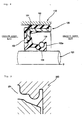
Fig. 1 is a half cross sectional view showing a preferable embodiment of an oil seal in accordance with the present invention by cutting along a plane passing through an axis O thereof; -
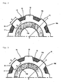
Fig. 2 is a view of an example of a shape of a holder portion in the present invention as seen from a direction A inFig. 1 ; -
Fig. 3 is a view of an other example of the shape of the holder portion in the present invention as seen from the direction A inFig. 1 ; -
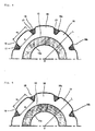
Fig. 4 is a view of an other example of the shape of the holder portion in the present invention as seen from the direction A inFig. 1 ; -
Fig. 5 is a view of an other example of the shape of the holder portion in the present invention as seen from the direction A inFig. 1 ; -
Fig. 6 is an enlarged view of a substantial part inFig. 1 ; -
Fig. 7 is a cross sectional view showing a part of a metal mold used for molding the oil seal inFig. 1 ; -
Fig. 8 is a half cross sectional view showing an oil seal in accordance with a related art by cutting along a plane passing through an axis O thereof; -
Fig. 9 is a cross sectional view showing a part of a metal mold used for molding the oil seal inFig. 8 ; -
Fig. 10 is a cross sectional view showing a mold releasing process after molding by the metal mold inFig. 9 ; and -
Fig. 11 is an explanatory view showing a conventional countermeasure example for preventing a crack from being generated in the mold releasing process. - Descriptions will be given below of an oil seal according to the present invention with reference to the accompanying drawings.
Fig. 1 is a half cross sectional view showing a preferable embodiment of the oil seal in accordance with the present invention by cutting along a plane passing through an axis O thereof,Figs. 2 to 5 are views of examples of a shape of a holder portion in the present invention as seen from a direction A inFig. 1 , andFig. 6 is an enlarged view of a substantial part inFig. 1 . - An
oil seal 1 shown inFig. 1 is provided between ashaft hole housing 2 of a device, and a rotatingshaft 3 concentrically and rotatably inserted to an inner periphery thereof, and is integrally molded by a rubber-like elastic material in ametal ring 14. Specifically, theoil seal 1 has an approximately cylindrical press-in fixedportion 11, anintermediate portion 12 extending from an end portion forming a machine outer side thereof to an inner peripheral side, aseal lip 13 extending toward a machine inner side in such a manner as to form an approximately C-shaped cross section together with the press-in fixedportion 11 and theintermediate portion 12 from an inner peripheral end of theintermediate portion 12, the reinforcingmetal ring 14 embedded astride the press-in fixedportion 11 and theintermediate portion 12, and agarter spring 15 fitted and attached to an outer periphery of theseal lip 13. - The
metal ring 14 is formed as an approximately L-shaped cross sectional bent shape including acylinder portion 14a embedded in the press-in fixedportion 11 and aflange portion 14b embedded in theintermediate portion 12. The press-in fixedportion 11 is a portion which is pressed into and closely fitted to an inner peripheral surface of theshaft hole housing 2, and is structured such that a suitable crush-out is given in a diametrical direction between thecylindrical portion 14a of themetal ring 14 and the inner peripheral surface of theshaft hole housing 2, in an installed state. In this case, anotch 11a formed in the inner peripheral portion of the press-in fixedportion 11, andnotches intermediate portion 12 so as to be positioned in both surfaces of theflange portion 14b of themetal ring 14 are molded traces formed by a convex portion or the like for positioning and fixing themetal ring 14 within the metal mold mentioned below, at a time of molding theoil seal 1. - The
seal lip 13 is structured such that alip edge 13a formed as an approximately V-shaped cross section is formed in an inner periphery in the vicinity of a leading end directed to the machine inner side, and thelip edge 13a is slidably brought into close contact with an outer peripheral surface of the rotatingshaft 3 with a suitable fastening margin. - A
groove 13b formed as a semicircular cross sectional shape is formed in an outer periphery of theseal lip 13 continuously in a circumferential direction so as to be positioned in an outer peripheral side of thelip edge 13a, and thegarter spring 15 is fitted and attached to thegroove 13b. Thegarter spring 15 is structured by connecting metal coil springs in a ring shape, and compensates for a tensioning force of theseal lip 13 with respect to the rotatingshaft 3. - A plurality of
holder portions 16 pressing thegarter spring 15 are formed in an outer periphery of the leading end portion of theseal lip 13, that is, the outer periphery in the leading end side of theseal lip 13 than thegroove 13b to which thegarter spring 15 is fitted and attached, so as to be spaced at a predetermined interval in a circumferential direction. - In an example shown in
Fig. 2 , each of theholder portions 16 is structured such that bothside surfaces holder portion 16 and an axis O, and a width wo in the circumferential direction in an outer diameter side is accordingly equal to a width wI in the circumferential direction in an inner diameter side. - In an example shown in
Fig. 3 , each of theholder portions 16 is structured such that both theside surfaces holder portion 16 and the axis O, and the width wo in the circumferential direction in the outer diameter side is smaller than the width wi in the circumferential direction in the inner diameter side. - In an example shown in
Fig. 4 , each of theholder portions 16 is structured such that both theside surfaces holder portion 16 and the axis O, the width wo in the circumferential direction in the outer diameter side is accordingly equal to the width wi in the circumferential direction in the inner diameter side, and the widths wo and wi in the circumferential direction are larger than the example shown inFig. 2 (the width in the circumferential direction of the relativeconcave portion 17 between theholder portions - In an example shown in
Fig. 5 , each of theholder portions 16 is structured such that both theside surfaces holder portion 16 and the axis O, the width wo in the circumferential direction in the outer diameter side is smaller than the width wi in the circumferential direction in the inner diameter side, and the widths wo and wi in the circumferential direction are larger than the example shown inFig. 3 (the width in the circumferential direction of the relative concave portion between theholder portions - Further, as shown in
Fig. 6 , a relation r ≤ R ≤ rs is established, by setting a radius of the deepest portion of thegroove 13b to which thegarter spring 15 is fitted and attached to r, a radius of the relativeconcave portion 17 between theholder portions garter spring 15 fitted and attached to thegroove 13b to rs. The relation R ≤ rs is set because each of theholder portions 16 does not easily undergo bending deformation in the mold releasing process after molding if theconcave portion 17 is shallower than the coil center of thegarter spring 15, and the relation r ≤ R is set because the original function of theholder portion 16 pressing thegarter spring 15 is deteriorated if theconcave portion 17 is deeper than the deepest portion of thegroove 13b. -
Fig. 7 is a cross sectional view showing a part of a metal mold used for molding theoil seal 1 inFig. 1 . Specifically, ametal mold 4 shown inFig. 7 includes splitdies oil seal 1 inFig. 1 is formed integrally with themetal ring 14 by setting themetal ring 14 to which a vulcanization adhesive agent is applied in an inner surface of onesplit mold 41 so as to clamp the mold, and filling an unvulcanized molding rubber material within acavity 43 defined between thesplit molds metal ring 14 thereby so as to crosslink and harden. - After molding, a molded product (the oil seal 1) attached to the
split mold 41 in a fitted state is released after opening thesplit molds holder portion 16 in the leading end side outer periphery of theseal lip 13 is formed as a plural divided shape with respect to the circumferential direction, the molded product can easily undergo bending deformation. Further, since the width wo in the circumferential direction in the outer diameter side becomes equal to or less than the width wi in the circumferential direction in the inner diameter side, in theholder portion 16, each of theholder portions 16 and each of the diametricalconcave portions 41 a of thesplit mold 41 which is a forming surface corresponding thereto do not come to a biting state. Accordingly, since each of theholder portions 16 is pursed in the inner diameter side within each of the diametricalconcave portions 41a and is easily released from the inner surface of thesplit mold 41 while undergoing bending deformation, in the process of releasing the molded product (the oil seal 1) in the axial direction, the mold releasing resistance is significantly reduced, and it is possible to prevent the crack from being generated in theseal lip 13 due to the constrainedly pulling. - Further, since it is not accordingly necessary to reduce the height of the
holder portion 16 for the purpose of reducing the mold releasing resistance after molding, it is possible to secure the falling preventing function of thegarter spring 15 by theholder portion 16. - Further, in accordance with the illustrated embodiment, since the
holder portion 16 is formed so as to be separated into a plurality of holder portions in the circumferential direction, a flexibility of the leading end of theseal lip 13 is improved. As a result, it is possible to reduce the resistance at a time of inserting therotating shaft 3 to the inner periphery of theseal lip 13 so as to install, and it is possible to intend to reduce the sliding torque between theseal lip 13 and therotating shaft 3 in the used state shown inFig. 1 .
Claims (2)
- An oil seal (1), wherein a groove (13b) fitting and attaching a garter spring (15) is formed continuously in a circumferential direction, and a plurality of holder portions (16) pressing the garter spring (15) are formed at a predetermined interval in the circumferential direction so as to be positioned in a leading end side of the seal lip (13) than the groove, and are formed such that a width wo in the circumferential direction in an outer diameter side in each of the holder portions (16) becomes equal to or less than a width wi in the circumferential direction in an inner diameter side.
- An oil seal as claimed in claim 1, wherein a relation r ≤ R ≤ rs is satisfied, by setting a radius of a deepest portion of the groove (13b) to which the garter spring (15) is fitted and attached to r, a radius of a relative concave portion (17) between the holder portions (16) to R, and a radius of a coil center of the garter spring (15) fitted and attached to the groove (13b) to rs.
Applications Claiming Priority (1)
| Application Number | Priority Date | Filing Date | Title |
|---|---|---|---|
| JP2007274001A JP2009103177A (en) | 2007-10-22 | 2007-10-22 | Oil seal |
Publications (2)
| Publication Number | Publication Date |
|---|---|
| EP2053288A2 true EP2053288A2 (en) | 2009-04-29 |
| EP2053288A3 EP2053288A3 (en) | 2011-01-19 |
Family
ID=40303613
Family Applications (1)
| Application Number | Title | Priority Date | Filing Date |
|---|---|---|---|
| EP08018451A Withdrawn EP2053288A3 (en) | 2007-10-22 | 2008-10-22 | Oil seals |
Country Status (2)
| Country | Link |
|---|---|
| EP (1) | EP2053288A3 (en) |
| JP (1) | JP2009103177A (en) |
Cited By (2)
| Publication number | Priority date | Publication date | Assignee | Title |
|---|---|---|---|---|
| CN102829185A (en) * | 2012-09-24 | 2012-12-19 | 青岛开世密封工业有限公司 | Oil seal capable of preventing spring from falling off |
| US12044314B2 (en) | 2019-09-30 | 2024-07-23 | Nok Corporation | Sealing device |
Families Citing this family (3)
| Publication number | Priority date | Publication date | Assignee | Title |
|---|---|---|---|---|
| JP2017223258A (en) * | 2016-06-14 | 2017-12-21 | Nok株式会社 | Sealing device |
| KR102276457B1 (en) * | 2019-04-10 | 2021-07-12 | 평화오일씰공업 주식회사 | Durability improved oil seal for car break module |
| CN120187969A (en) | 2023-02-15 | 2025-06-20 | Nok株式会社 | Sealing device |
Citations (1)
| Publication number | Priority date | Publication date | Assignee | Title |
|---|---|---|---|---|
| JP2003336745A (en) | 2002-05-17 | 2003-11-28 | Keeper Co Ltd | Oil seal for power steering |
Family Cites Families (3)
| Publication number | Priority date | Publication date | Assignee | Title |
|---|---|---|---|---|
| US2692786A (en) * | 1950-04-27 | 1954-10-26 | Nat Motor Bearing Co Inc | Seal |
| US3746351A (en) * | 1971-07-19 | 1973-07-17 | Chicago Rawhide Mfg Co | Radial shaft seal with positively retained garter spring |
| JP2003262276A (en) * | 2002-03-08 | 2003-09-19 | Mitsubishi Cable Ind Ltd | Sealing device |
-
2007
- 2007-10-22 JP JP2007274001A patent/JP2009103177A/en active Pending
-
2008
- 2008-10-22 EP EP08018451A patent/EP2053288A3/en not_active Withdrawn
Patent Citations (1)
| Publication number | Priority date | Publication date | Assignee | Title |
|---|---|---|---|---|
| JP2003336745A (en) | 2002-05-17 | 2003-11-28 | Keeper Co Ltd | Oil seal for power steering |
Cited By (2)
| Publication number | Priority date | Publication date | Assignee | Title |
|---|---|---|---|---|
| CN102829185A (en) * | 2012-09-24 | 2012-12-19 | 青岛开世密封工业有限公司 | Oil seal capable of preventing spring from falling off |
| US12044314B2 (en) | 2019-09-30 | 2024-07-23 | Nok Corporation | Sealing device |
Also Published As
| Publication number | Publication date |
|---|---|
| JP2009103177A (en) | 2009-05-14 |
| EP2053288A3 (en) | 2011-01-19 |
Similar Documents
| Publication | Publication Date | Title |
|---|---|---|
| EP1729045B1 (en) | Sealing device for reciprocating shaft | |
| EP2275722B1 (en) | Lip type seal | |
| US7942424B2 (en) | Lip type seal | |
| US8256772B2 (en) | Lip type seal | |
| EP2088352B1 (en) | Sealing device | |
| CN106133413B (en) | Gasket | |
| JP2933483B2 (en) | Housing cover and seal assembly | |
| EP1956274A1 (en) | Installation structure of bore plug | |
| US8366117B2 (en) | Sealing device | |
| EP1223360A1 (en) | Attachment structure for a constant velocity joint boot | |
| US7922611B2 (en) | Power transmission system | |
| CN108700194B (en) | Disc brake and piston cover | |
| EP1760371A1 (en) | Sealing device | |
| EP1890057A1 (en) | Sealing device | |
| JP2009103177A (en) | Oil seal | |
| EP3916272A1 (en) | Gasket | |
| EP3006749A1 (en) | Ball joint dust cover | |
| US6814356B2 (en) | Installation structure of bearing seal | |
| CN106233015B (en) | Reusable dust cover for pulley assemblies | |
| JP2017223258A (en) | Sealing device | |
| JP2017227243A (en) | Fixing structure of sealing device | |
| JP4957937B2 (en) | Sealing device | |
| JP2007107550A (en) | Sealing device for reciprocating shaft | |
| JP4396820B2 (en) | Oil seal | |
| JP2006250160A (en) | Gasket |
Legal Events
| Date | Code | Title | Description |
|---|---|---|---|
| PUAI | Public reference made under article 153(3) epc to a published international application that has entered the european phase |
Free format text: ORIGINAL CODE: 0009012 |
|
| AK | Designated contracting states |
Kind code of ref document: A2 Designated state(s): AT BE BG CH CY CZ DE DK EE ES FI FR GB GR HR HU IE IS IT LI LT LU LV MC MT NL NO PL PT RO SE SI SK TR |
|
| AX | Request for extension of the european patent |
Extension state: AL BA MK RS |
|
| PUAL | Search report despatched |
Free format text: ORIGINAL CODE: 0009013 |
|
| AK | Designated contracting states |
Kind code of ref document: A3 Designated state(s): AT BE BG CH CY CZ DE DK EE ES FI FR GB GR HR HU IE IS IT LI LT LU LV MC MT NL NO PL PT RO SE SI SK TR |
|
| AX | Request for extension of the european patent |
Extension state: AL BA MK RS |
|
| 17P | Request for examination filed |
Effective date: 20110126 |
|
| AKX | Designation fees paid |
Designated state(s): AT BE BG CH CY CZ DE DK EE ES FI FR GB GR HR HU IE IS IT LI LT LU LV MC MT NL NO PL PT RO SE SI SK TR |
|
| GRAP | Despatch of communication of intention to grant a patent |
Free format text: ORIGINAL CODE: EPIDOSNIGR1 |
|
| RIN1 | Information on inventor provided before grant (corrected) |
Inventor name: NOJI, TOSHIAKI Inventor name: SATO, MASAKI Inventor name: OIZUMI, MASAKI |
|
| STAA | Information on the status of an ep patent application or granted ep patent |
Free format text: STATUS: THE APPLICATION IS DEEMED TO BE WITHDRAWN |
|
| 18D | Application deemed to be withdrawn |
Effective date: 20120523 |