EP2053257A2 - Device for blocking the rotation of a screwed assembly, assembly comprising such a device and use of such an assembly in aeronautical construction - Google Patents
Device for blocking the rotation of a screwed assembly, assembly comprising such a device and use of such an assembly in aeronautical construction Download PDFInfo
- Publication number
- EP2053257A2 EP2053257A2 EP08167148A EP08167148A EP2053257A2 EP 2053257 A2 EP2053257 A2 EP 2053257A2 EP 08167148 A EP08167148 A EP 08167148A EP 08167148 A EP08167148 A EP 08167148A EP 2053257 A2 EP2053257 A2 EP 2053257A2
- Authority
- EP
- European Patent Office
- Prior art keywords
- washer
- assembly
- lug
- rotation
- nut
- Prior art date
- Legal status (The legal status is an assumption and is not a legal conclusion. Google has not performed a legal analysis and makes no representation as to the accuracy of the status listed.)
- Granted
Links
- 238000010276 construction Methods 0.000 title claims description 10
- 230000000903 blocking effect Effects 0.000 title description 3
- 239000000463 material Substances 0.000 claims abstract description 8
- 230000000295 complement effect Effects 0.000 claims description 10
- 230000003100 immobilizing effect Effects 0.000 claims description 3
- 210000002105 tongue Anatomy 0.000 claims description 3
- 229910000831 Steel Inorganic materials 0.000 description 2
- 239000000314 lubricant Substances 0.000 description 2
- 230000001681 protective effect Effects 0.000 description 2
- 239000010959 steel Substances 0.000 description 2
- 230000001174 ascending effect Effects 0.000 description 1
- 230000004323 axial length Effects 0.000 description 1
- 230000000694 effects Effects 0.000 description 1
- 238000002955 isolation Methods 0.000 description 1
- 238000004519 manufacturing process Methods 0.000 description 1
- 238000003032 molecular docking Methods 0.000 description 1
- VEVKLOLYYQLRRV-UHFFFAOYSA-N moretenone Natural products C12CCC3C4(C)CCC(=O)C(C)(C)C4CCC3(C)C1(C)CCC1C2(C)CCC1C(=C)C VEVKLOLYYQLRRV-UHFFFAOYSA-N 0.000 description 1
- 230000000149 penetrating effect Effects 0.000 description 1
- 230000000750 progressive effect Effects 0.000 description 1
- 230000001012 protector Effects 0.000 description 1
- 230000000284 resting effect Effects 0.000 description 1
- 230000000717 retained effect Effects 0.000 description 1
Images


Classifications
-
- F—MECHANICAL ENGINEERING; LIGHTING; HEATING; WEAPONS; BLASTING
- F16—ENGINEERING ELEMENTS AND UNITS; GENERAL MEASURES FOR PRODUCING AND MAINTAINING EFFECTIVE FUNCTIONING OF MACHINES OR INSTALLATIONS; THERMAL INSULATION IN GENERAL
- F16B—DEVICES FOR FASTENING OR SECURING CONSTRUCTIONAL ELEMENTS OR MACHINE PARTS TOGETHER, e.g. NAILS, BOLTS, CIRCLIPS, CLAMPS, CLIPS OR WEDGES; JOINTS OR JOINTING
- F16B39/00—Locking of screws, bolts or nuts
- F16B39/22—Locking of screws, bolts or nuts in which the locking takes place during screwing down or tightening
- F16B39/24—Locking of screws, bolts or nuts in which the locking takes place during screwing down or tightening by means of washers, spring washers, or resilient plates that lock against the object
-
- F—MECHANICAL ENGINEERING; LIGHTING; HEATING; WEAPONS; BLASTING
- F16—ENGINEERING ELEMENTS AND UNITS; GENERAL MEASURES FOR PRODUCING AND MAINTAINING EFFECTIVE FUNCTIONING OF MACHINES OR INSTALLATIONS; THERMAL INSULATION IN GENERAL
- F16B—DEVICES FOR FASTENING OR SECURING CONSTRUCTIONAL ELEMENTS OR MACHINE PARTS TOGETHER, e.g. NAILS, BOLTS, CIRCLIPS, CLAMPS, CLIPS OR WEDGES; JOINTS OR JOINTING
- F16B39/00—Locking of screws, bolts or nuts
- F16B39/02—Locking of screws, bolts or nuts in which the locking takes place after screwing down
- F16B39/10—Locking of screws, bolts or nuts in which the locking takes place after screwing down by a plate, spring, wire or ring immovable with regard to the bolt or object and mainly perpendicular to the axis of the bolt
- F16B39/108—Locking of screws, bolts or nuts in which the locking takes place after screwing down by a plate, spring, wire or ring immovable with regard to the bolt or object and mainly perpendicular to the axis of the bolt with a locking washer under the nut or bolt head having at least one tongue or lug folded against the nut or bolt head, or against the object itself
-
- F—MECHANICAL ENGINEERING; LIGHTING; HEATING; WEAPONS; BLASTING
- F16—ENGINEERING ELEMENTS AND UNITS; GENERAL MEASURES FOR PRODUCING AND MAINTAINING EFFECTIVE FUNCTIONING OF MACHINES OR INSTALLATIONS; THERMAL INSULATION IN GENERAL
- F16B—DEVICES FOR FASTENING OR SECURING CONSTRUCTIONAL ELEMENTS OR MACHINE PARTS TOGETHER, e.g. NAILS, BOLTS, CIRCLIPS, CLAMPS, CLIPS OR WEDGES; JOINTS OR JOINTING
- F16B2200/00—Constructional details of connections not covered for in other groups of this subclass
- F16B2200/69—Redundant disconnection blocking means
Definitions
- the present invention relates to a rotational locking device for immobilizing a screw connection. Furthermore, the invention relates to a screw connection comprising such a locking device in rotation. On the other hand, the invention relates to the use of such an assembly for aeronautical construction. The present invention thus relates to the field of mechanical components for screw connection, in particular in the field of aeronautical construction.
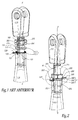
- FIG. 1 illustrates, in the released position, a screw assembly of the prior art as used in the field of aeronautical construction and comprising a braking device of the prior art for preventing the unscrewing of this assembly.
- the assembly comprises a conrod head for the aeronautical construction forming a tip 110, a rod body forming a tube 100, and a braking device 1 and a nut 180.
- the tip 110 is provided with a threaded rod 111 which can be screwed into a corresponding thread of the tube 100 and on which is tightened the nut 180.
- the braking device 1 comprises a first washer 120, a second washer 140 and a not shown brake wire.
- the washers 120 and 140 are threaded onto the threaded rod 111 between the tube 100 and the nut 180.
- the washer 120 comprises two tenons disposed on its side facing the tube 100, one of which is shown in FIG. figure 1 with the reference 123.
- the post 123 cooperates with a notch 103 located on the end of the tube 100, which allows to lock the washer 120 in rotation relative to the tube 100.
- the faces of the washers 120 and 140 which are intended to be in contact after tightening of the braking device comprise complementary ridges forming so many mutual locking means in rotation of the washers 120 and 140.
- the inner periphery of the second washer 140 is provided with a key 143 which penetrates into a longitudinal groove 113 made along the threaded rod 111. The washer 140 is thus locked in rotation with respect to the threaded rod 111.
- the nut 180 and the washers 120 and 140 are pressed against the tube 100 and the washers 120 and 140 are mutually locked in rotation by the interlocking of their streaks.
- the outer periphery of the first washer 120 has a lug 125 pierced with a hole 126.
- the nut 180 has three holes 181, 182 and 183 drilled in substantially orthoradial directions. To brake the nut in the unscrewing direction and thus maintain the cohesion of the assembly, an operator must pass a braking wire through the holes 126 and 181 to 183, then tighten the braking wire by twisting it on itself. even. The brake wire thus maintains contact between the nut, the washers and the tube.
- the present invention aims in particular to overcome these disadvantages, by proposing a rotational locking device for screwed assembly effective, reliable, simple and quick to assemble, economical and without risk of snagging for operators.
- mouthpiece is used here in the generic sense. In the field of aeronautical construction, it may designate an extension or a tip itself provided with a fastening component. More generally, the term mouthpiece here designates any part comprising a threaded rod, or even a threaded rod itself, that is to say a simple rod provided with a thread
- a rotational locking device therefore has increased reliability and simplicity of mounting.
- An assembly according to the invention comprising such a device is faster to mount, without risk of error, while having a good accuracy of adjustment of the thread length engaged.
- the braking device according to the invention does not have any projecting piece likely to hook an operator.
- the assembly according to the invention requires more specially drilled nut for the wire brake and the rotational locking device is compatible with the existing tips and tubes.
- the subject of the invention is an assembly comprising a nozzle provided with a thread to be screwed into a tube, a nut that can be screwed onto the endpiece, this endpiece comprising at least one longitudinal groove extending along the threading axis of the nozzle, this tube comprising at least one rotational locking element located on its end of receiving the tip, characterized in that it comprises a locking device in rotation as explained above , so as to immobilize this assembly.
- the subject of the invention is the use for the aeronautical construction of an assembly as set out above, in which the tube is a rod body and the end piece is a small end.
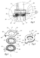
- the assembly illustrated by the figures 2 and 3 comprises a tube 200, a nozzle 210 and a device 2 for locking the assembly in rotation.
- the tube 200 and the nozzle 210 consist respectively of a body and a small end used in the aeronautical construction.
- the elements of the assembly illustrated in figure 2 which correspond to elements of the assembly of the prior art illustrated in FIG. figure 1 , have the same references increased by 100.
- the tip 210 is provided with a threading formed on a rod 211 intended to be screwed into a corresponding thread of the tube 200.
- the threaded rod 211 comprises a longitudinal groove 213 similar to the groove 113, which extends along the axis ZZ 'of the thread of the nozzle 210 and which is shown in dotted lines on the figure 2 .
- the tube 200 comprises two notches 203 and 204, which are located on the end of the tube 200 intended to receive the nozzle 210.
- the notches 203 and 204 are formed along the same diameter of the tube 200 and they constitute elements blocking rotation of the tube 200 relative to the device 2, as explained below.
- the device 2 comprises a first washer 220 and a second washer 240.
- the lower face 222 of the first washer 220 comprises two pins 223 and 224.
- the tenons 223 and 224 constitute rotational locking components of the washer 220 relative to the 200.
- the studs 223 and 224 are adapted to cooperate, by complementarity of shapes, respectively with the notches 203 and 204.
- the inner periphery of the second washer 240 that is to say its radial wall facing the Z-Z 'axis, comprises a protruding key 243, which is able to penetrate into the longitudinal groove 213, so as to block in rotation the second washer 240 relative to the nozzle 210.
- the upper face 221 of the washer 220 and the lower face 242 of the washer 240 comprise mutual locking means in rotation, which here comprise two sets of radial grooves with complementary profiles.
- the adjectives "lower” and “higher” are used here with reference to the upward direction of the Z-Z 'axis.
- the streaks have a profile of triangular teeth. They extend radially from the axis ZZ 'on the majority of the faces 221 and 242, thus offering a multitude of adjustment positions between the washers 220 and 240. After mutual clamping of the streaks under the action of a pair of tightening, the washers 220 and 240 have no relative movement possible.
- the outer periphery, that is to say the outer radial wall, of the first washer 220 is associated with a projecting lug 225 which contributes to the rotational locking of the assembly, as explained below.
- the pin 225 has a flat profile. Its thickness is of the order of that of the unstriated portion of the first washer 220.
- the device 2 further comprises a third washer 260 which is disposed above and in contact with the upper face 241 of the second washer 240.
- a tab 265 which is adapted to cooperating by complementary shapes with the pin 225, so as to lock the washer 260 in rotation relative to the washer 220.
- the tab 265 comprises an angled portion "L" which forms a free wing pierced with a light 266 oblong and adapted to receive the end portion of the pin 225. In the position of cooperation, as shown by the Figures 5 to 8 , the pin 225 passing through the light 266 blocks the relative rotation between, on the one hand, the first washer 220 and, on the other hand, the third washer 260.
- the immobilization of the assembly is achieved by clamping the device 2 against the end of the tube 200 by means of a nut 280 It will be noted that the nut 280 is full, that is to say that it does not require holes.
- the three washers 220, 240 and 260, in the form of annular elements, are intended to be superimposed and contiguous after immobilization of the assembly.
- the upper face of the washer 260, on which the nut 280 is intended to rest may be coated with dry or greasy lubricant or protective product, so as to reduce the risk of it being entrained in rotation. This also allows a progressive tightening of the nut 280, which induces a homogeneous prestressing of the thread.
- the first and the second washer 220 and 240 may be coated with lubricant and / or protector.
- the washer 260 further comprises two tabs 268 and 269 which extend at its outer periphery and which are foldable towards the axis ZZ 'and on at least two sides of the hexagonal nut 280.
- the tongues 268 and 269 constitute, after have been folded and folded against the nut 280, a locking member of the nut 280 in rotation relative to the washer 260.
- Each of the three washers 220, 240 and 260 has a generally flat and cylindrical shape with a circular base and a central axis Z-Z '.
- the three washers 220, 240 and 260 constituting the rotational locking device 2 of the assembly therefore represent a limited axial space.
- Each of the three washers 220, 240 and 260 may also be replaced by a non-circular annular element in section, at least at the outer periphery.
- the washer 220 and the washer 240 are advantageously made of a hard material, such as X5CrNiCuNb 17-04 steel or equivalent.
- the washer 260 is made of a ductile material such as X2CrNi 18-9 steel or equivalent.
- the second washer 240 can rotate freely relative to the washers 220 and 260. This freedom of rotation and the presence of the grooves on the faces 221 and 242 make it possible to obtain a stepwise adjustment, in particular micrometric pitch according to the dimensions of the thread and each streak, for the relative longitudinal positioning of the tip 210 relative to the tube 200.
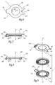
- the figure 9 illustrates a rotational locking device 3 according to a second embodiment of the invention.
- the description of the device 2 given above in relation to the Figures 2 to 8 may be transposed to device 3.
- the elements of the device 3 identical or corresponding to those of the device 2 illustrated on the Figures 2 to 8 have the same references increased by 100.
- the device 3 differs from the device 2 in that the lug 325 of the first washer 320 has a profile in "Z", instead of a flat profile, a bent wing 327 is directed towards the third washer 360.
- Profile here denotes the section of an element by a plane passing through the axis Z-Z '.
- the end portion of the lug 325 is received in a rectangular slot 366 and pierced in the free flange of the bent tab 365.
- Such a geometry makes it possible to reduce the axial length of the tab 365 of the washer 360 relative to the tab 265, which facilitates the passage of a key resting on flats 201 and 202, shown in FIG. figure 2 , so as to maintain the tube 200 during the screwing of the nut on the assembly.
- the pin 325 can thus withstand greater tightening or loosening torques.
- FIGS 10 to 13 illustrate a device 4 according to a third embodiment of the invention.
- the description of the device 2 given above with reference to Figures 2 to 8 may be transposed to the device 4.
- the elements of the device 4 identical or corresponding to those of the device 2 have the same references increased by 200.
- the device 4 differs from the device 2 in that the lug 425 and the lug 465 have "Z" profiles converging towards one another.
- the locking of the first washer 420 relative to the third washer 460 is here produced by the passage of the tab 465 through a rectangular slot 426 formed in the lug 425, unlike the device 2.
- the lumen 426 extends in a plane transverse to the axis ZZ '.
- Such a shape makes it possible to further reduce the axial space occupied by the lug 465 and the lug 425 in the tight position, with respect to the device 2 or 3.
- the lug 465 and the lug 425 have an increased robustness that allows them to withstand greater tightening or loosening torques.
- the device 4 facilitates the passage of a key to maintain the tube 200.
- the light 426 is formed in the lug 425 instead of the lug 465, it is possible to use the first washer 420 as a docking point for a brake wire, so that the device 4 can also be used. be used as a brake wire braking device of the prior art, such as that illustrated by the figure 1 .
- the assembly can dispense with the third washer 460, provided to use a drilled nut such as the nut 180 of the figure 1 .
- the width of the light 426 allows the passage of two strands of the same brake wire. This allows a symmetrical mounting of the brake wire, so an undifferentiated mounting according to the left or right orientation of the pitch of the thread, which avoids the risk of errors during its assembly.
- the construction of the device 4 also makes it possible to stop the rotation of the third washer 460 during the micrometric adjustment between the washers 420 and 440.
- the washer 460 can no longer dissociate from the washer 420 during the micrometric adjustment.
- the washer 420 is locked in rotation, relative to the tube 200, by means of its pins 423 and 424.
- the washer 460 is locked in rotation relative to the washer 420, by means of its lug 465 retained in the light 426.
- the washer 440 is rotated by means of its key 443 held in the groove 213 of the threaded rod 211.
- FIGS. 14 and 15 illustrate a device 5 according to a fourth embodiment of the invention.
- the description of the device 2 given above with reference to the figures 4 and 8 may be transposed to the device 5.
- the elements of the device 5 identical or corresponding to those of the device 2 have the same references increased by 300.
- the lug 545 is associated with the outer periphery of the second washer 540 rather than that of the first washer 520. This facilitates the production of the locking device 5 in rotation. It may however be desirable to lock the nut as directly as possible relative to the tube and thus to associate the lug with the first washer.
- the tube to lock in rotation the tube relative to the first washer, it can provide a single pair tenon-notch or, conversely, more than two pairs tenon-notch, depending on the tightening torque or loosening to bear.
- the determination of the number and dimensions of the tenon (s) and notch (s) depends on the mechanical stresses they are intended to undergo.
- it can be provided to make one or more notches (s) on the first washer and one or more tenon (s) on the tube.
- Such a geometry corresponds to the inverse of the structures illustrated by the figures.
- the light of the lug may have an open profile.
Abstract
Description
La présente invention concerne un dispositif de blocage en rotation, pour immobiliser un assemblage vissé. Par ailleurs, l'invention concerne un assemblage vissé comprenant un tel dispositif de blocage en rotation. D'autre part, l'invention concerne l'utilisation d'un tel assemblage pour la construction aéronautique. La présente invention se rapporte donc au domaine des composants mécaniques pour assemblage vissé, en particulier dans le domaine de la construction aéronautique.The present invention relates to a rotational locking device for immobilizing a screw connection. Furthermore, the invention relates to a screw connection comprising such a locking device in rotation. On the other hand, the invention relates to the use of such an assembly for aeronautical construction. The present invention thus relates to the field of mechanical components for screw connection, in particular in the field of aeronautical construction.
De l'art antérieur, on connaît un dispositif de freinage en rotation, pour maintenir un assemblage vissé et empêcher son dévissage intempestif, par exemple sous l'effet de vibrations. La
Le dispositif de freinage 1 comprend une première rondelle 120, une deuxième rondelle 140 et un fil-frein non représenté. Les rondelles 120 et 140 sont enfilées sur la tige filetée 111 entre le tube 100 et l'écrou 180. La rondelle 120 comporte deux tenons disposés sur sa face tournée vers le tube 100, dont l'un est représenté à la
La périphérie interne de la deuxième rondelle 140 est munie d'une clavette 143 qui pénètre dans une rainure longitudinale 113 réalisée le long de la tige filetée 111. La rondelle 140 est ainsi bloquée en rotation par rapport à la tige filetée 111.The inner periphery of the second washer 140 is provided with a
Après serrage de l'écrou 180 sur la tige filetée 111, l'écrou 180 et les rondelles 120 et 140 sont comprimés contre le tube 100 et les rondelles 120 et 140 sont mutuellement bloquées en rotation par l'imbrication de leurs stries.After tightening the
La périphérie externe de la première rondelle 120 comporte un ergot 125 percé d'un trou 126. L'écrou 180 comporte trois trous 181, 182 et 183 percés selon des directions sensiblement orthoradiales. Pour freiner l'écrou dans le sens du dévissage et maintenir ainsi la cohésion de l'assemblage, un opérateur doit passer un fil-frein à travers les trous 126 et 181 à 183, puis tendre le fil-frein en le torsadant sur lui-même. Le fil-frein maintient ainsi le contact entre l'écrou, les rondelles et le tube.The outer periphery of the
Cependant, un tel assemblage est relativement long à réaliser, notamment en raison du passage du fil-frein par l'opérateur. En outre, il existe un risque d'erreur dans le sens de montage du fil-frein, car le pas du filetage peut être à gauche ou à droite. De plus, la qualité du freinage en rotation assurée par le fil-frein dépend de la tension donnée au fil-frein par l'opérateur ; si l'opérateur tend insuffisamment le fil-frein, l'écrou et donc le dispositif de freinage peuvent se desserrer dans une certaine mesure.However, such an assembly is relatively long to achieve, in particular due to the passage of the wire-brake by the operator. In addition, there is a risk of error in the mounting direction of the brake wire, because the pitch of the thread can be left or right. In addition, the quality of the rotational braking provided by the brake wire depends on the voltage given to the wire brake by the operator; if the operator insufficiently strains the brake wire, the nut and therefore the braking device can loosen to a certain extent.
En outre, un tel assemblage nécessite un écrou spécifique puisque percé, ce qui en augmente le coût. Par ailleurs, l'extrémité torsadée du fil-frein peut blesser un opérateur ou accrocher ses vêtements de protection, ce qui est rédhibitoire pour certaines applications aéronautiques.In addition, such an assembly requires a specific nut since pierced, which increases the cost. Furthermore, the twisted end of the brake wire can injure an operator or hang his protective clothing, which is unacceptable for certain aeronautical applications.
La présente invention vise notamment à remédier à ces inconvénients, en proposant un dispositif de blocage en rotation pour assemblage vissé efficace, fiable, simple et rapide à monter, économique et sans risque d'accrochage pour les opérateurs.The present invention aims in particular to overcome these disadvantages, by proposing a rotational locking device for screwed assembly effective, reliable, simple and quick to assemble, economical and without risk of snagging for operators.
A cet effet, l'invention a pour objet un dispositif de blocage en rotation, pour immobiliser un assemblage comprenant un embout muni d'un filetage vissé dans un tube, ledit embout comportant au moins une rainure longitudinale s'étendant selon l'axe de filetage de l'embout, ledit tube comportant au moins un élément de blocage en rotation situé sur son extrémité de réception de l'embout, ainsi qu'un écrou apte à être vissé sur l'embout, le dispositif comprenant :
- une première rondelle dont une première face est pourvue d'au moins un composant de blocage en rotation apte à coopérer avec ledit élément de blocage en rotation, et
- une deuxième rondelle dont la périphérie interne est munie d'au moins une clavette apte à pénétrer dans ladite rainure longitudinale,
caractérisé en ce qu'il comprend, en outre, une troisième rondelle comportant au moins un organe de blocage en rotation de l'écrou, et en ce que la périphérie externe de la troisième rondelle comporte au moins une patte adaptée pour coopérer par complémentarité de formes avec ledit ergot, de façon à bloquer en rotation, d'une part, la première ou la deuxième rondelle associée à l'ergot et, d'autre part, la troisième rondelle.For this purpose, the subject of the invention is a rotational locking device, for immobilizing an assembly comprising an end piece provided with a thread screwed into a tube, said end-piece comprising at least one groove longitudinal extending along the thread axis of the endpiece, said tube comprising at least one rotational locking element located on its end of receiving the endpiece, and a nut adapted to be screwed onto the endpiece. the device comprising:
- a first washer whose first face is provided with at least one rotational locking component adapted to cooperate with said rotational locking element, and
- a second washer whose inner periphery is provided with at least one key capable of penetrating into said longitudinal groove,
characterized in that it further comprises a third washer comprising at least one locking member in rotation of the nut, and in that the outer periphery of the third washer comprises at least one tab adapted to cooperate by complementarity of forms with said lug, so as to lock in rotation, on the one hand, the first or the second washer associated with the lug and, secondly, the third washer.
Le terme embout est ici employé au sens générique. Dans le domaine de la construction aéronautique, il peut désigner un prolongateur ou un embout proprement dit muni d'un composant d'accrochage. Plus généralement, le terme embout désigne ici toute pièce comprenant une tige filetée, voire une tige filetée elle-même, c'est-à-dire une simple tige munie d'un filetageThe term mouthpiece is used here in the generic sense. In the field of aeronautical construction, it may designate an extension or a tip itself provided with a fastening component. More generally, the term mouthpiece here designates any part comprising a threaded rod, or even a threaded rod itself, that is to say a simple rod provided with a thread
Un dispositif de blocage en rotation conforme à la présente invention présente donc une fiabilité et une simplicité de montage accrue. Un assemblage conforme à l'invention comprenant un tel dispositif s'avère plus rapide à monter, sans risque d'erreur, tout en présentant une bonne précision de réglage de la longueur de filetage en prise. De plus, le dispositif de freinage conforme à l'invention ne présente pas de pièce saillante susceptible d'accrocher un opérateur. Par ailleurs, l'assemblage conforme à l'invention ne nécessite plus d'écrou spécifiquement percé pour le fil-frein et le dispositif de blocage en rotation est compatible avec les embouts et tubes actuels.A rotational locking device according to the present invention therefore has increased reliability and simplicity of mounting. An assembly according to the invention comprising such a device is faster to mount, without risk of error, while having a good accuracy of adjustment of the thread length engaged. In addition, the braking device according to the invention does not have any projecting piece likely to hook an operator. Moreover, the assembly according to the invention requires more specially drilled nut for the wire brake and the rotational locking device is compatible with the existing tips and tubes.
Selon des caractéristiques avantageuses mais facultatives de l'invention, prises isolément ou selon toute combinaison techniquement admissible :
- l'ergot est associé à la première rondelle ;
- chaque rondelle présente une forme globalement plate et cylindrique ;
- l'ergot présente un profil plat ou coudé et la patte comprend une partie coudée formant une aile percée d'une lumière adaptée pour recevoir, de manière complémentaire, une partie terminale de l'ergot ;
- la patte présente un profil en Z et l'ergot présente un profil plat ou coudé ainsi qu'une lumière adaptée pour recevoir, de manière complémentaire, une partie terminale de la patte ;
- les moyens de blocage mutuel en rotation des première et deuxième rondelles comprennent deux séries de stries complémentaires ;
- l'organe de blocage en rotation de l'écrou comporte deux languettes qui s'étendent à la périphérie externe de la troisième rondelle et qui sont rabattables sur l'écrou ;
- les première et deuxième rondelles sont réalisées en un matériau dur et la troisième rondelle est réalisée en un matériau ductile.
- the lug is associated with the first washer;
- each washer has a generally flat and cylindrical shape;
- the lug has a flat or bent profile and the lug comprises a bent portion forming a wing pierced with a light adapted to receive, in a complementary manner, an end portion of the lug;
- the tab has a Z-shaped profile and the lug has a flat or bent profile and a light adapted to receive, in a complementary manner, an end portion of the lug;
- the mutual rotational locking means of the first and second washers comprise two sets of complementary striations;
- the locking member in rotation of the nut comprises two tongues which extend to the outer periphery of the third washer and which are foldable on the nut;
- the first and second washers are made of a hard material and the third washer is made of a ductile material.
Par ailleurs, l'invention a pour objet un assemblage comprenant un embout muni d'un filetage à visser dans un tube, un écrou apte à être vissé sur l'embout, cet embout comportant au moins une rainure longitudinale s'étendant selon l'axe de filetage de l'embout, ce tube comportant au moins un élément de blocage en rotation situé sur son extrémité de réception de l'embout, caractérisé en ce qu'il comprend un dispositif de blocage en rotation tel qu'exposé ci-dessus, de façon à immobiliser cet assemblage.Furthermore, the subject of the invention is an assembly comprising a nozzle provided with a thread to be screwed into a tube, a nut that can be screwed onto the endpiece, this endpiece comprising at least one longitudinal groove extending along the threading axis of the nozzle, this tube comprising at least one rotational locking element located on its end of receiving the tip, characterized in that it comprises a locking device in rotation as explained above , so as to immobilize this assembly.
D'autre part, l'invention a pour objet l'utilisation pour la construction aéronautique d'un assemblage tel qu'exposé ci-dessus, dans laquelle le tube est un corps de bielle et l'embout est une tête de bielle.On the other hand, the subject of the invention is the use for the aeronautical construction of an assembly as set out above, in which the tube is a rod body and the end piece is a small end.
La présente invention sera bien comprise et ses avantages ressortiront aussi à la lumière de la description qui va suivre, donnée uniquement à titre d'exemple et faite en référence aux dessins annexés, dans lesquels :
- la
figure 1 est une vue en perspective d'un assemblage de l'art antérieur ; - la
figure 2 est une vue en perspective d'un assemblage conforme à l'invention, à l'état serré et comprenant un dispositif de blocage conforme à l'invention ; - la
figure 3 est une vue à plus grande échelle du détail III de lafigure 2 ; - la
figure 4 est une vue en perspective éclatée du dispositif de blocage de lafigure 2 ; - la
figure 5 est une vue en perspective du dispositif de blocage de lafigure 4 , dans une position de réglage ; - la
figure 6 est une vue de dessus du dispositif de lafigure 5 ; - la
figure 7 est une vue de côté du dispositif de lafigure 5 , dans sa position de réglage ; - la
figure 8 est une vue analogue à lafigure 7 , montrant le dispositif de blocage dans la position serrée de lafigure 3 ; - la
figure 9 est une vue en perspective éclatée d'un dispositif de blocage conforme à un deuxième mode de réalisation de l'invention ; - la
figure 10 est une vue en perspective éclatée d'un dispositif de blocage conforme à un troisième mode de réalisation de l'invention ; - la
figure 11 est une vue analogue à lafigure 5 du dispositif de lafigure 10 ; - la
figure 12 est une vue de dessus du dispositif de lafigure 10 ; - la
figure 13 est une vue de côté du dispositif de lafigure 11 , dans une position de réglage ; - la
figure 14 est une vue en perspective éclatée d'un dispositif de blocage conforme à un quatrième mode de réalisation de l'invention ; et - la
figure 15 est une vue de côté du dispositif de lafigure 14 à l'état serré.
- the
figure 1 is a perspective view of an assembly of the prior art; - the
figure 2 is a perspective view of an assembly according to the invention, in the tightened state and comprising a locking device according to the invention; - the
figure 3 is a larger-scale view of detail III of thefigure 2 ; - the
figure 4 is an exploded perspective view of the locking device of thefigure 2 ; - the
figure 5 is a perspective view of the blocking device of thefigure 4 in a setting position; - the
figure 6 is a top view of the device of thefigure 5 ; - the
figure 7 is a side view of the device of thefigure 5 in its adjustment position; - the
figure 8 is a view similar to thefigure 7 , showing the locking device in the tight position of thefigure 3 ; - the
figure 9 is an exploded perspective view of a locking device according to a second embodiment of the invention; - the
figure 10 is an exploded perspective view of a locking device according to a third embodiment of the invention; - the
figure 11 is a view similar to thefigure 5 of the device of thefigure 10 ; - the
figure 12 is a top view of the device of thefigure 10 ; - the
figure 13 is a side view of the device of thefigure 11 in a setting position; - the
figure 14 is an exploded perspective view of a locking device according to a fourth embodiment of the invention; and - the
figure 15 is a side view of the device of thefigure 14 in the tight state.
L'assemblage illustré par les
L'embout 210 est muni d'un filetage réalisé sur une tige 211 destinée à être vissée dans un filetage correspondant du tube 200. La tige filetée 211 comporte une rainure longitudinale 213 semblable à la rainure 113, qui s'étend selon l'axe Z-Z' du filetage de l'embout 210 et qui est représentée en traits pointillés sur la
Le tube 200 comporte deux encoches 203 et 204, qui sont situées sur l'extrémité du tube 200 destinée à recevoir l'embout 210. Les encoches 203 et 204 sont réalisées le long d'un même diamètre du tube 200 et elles constituent des éléments de blocage en rotation du tube 200 par rapport au dispositif 2, comme cela est exposé ci-après.The
Comme le montrent les
La périphérie interne de la deuxième rondelle 240, c'est-à-dire sa paroi radiale tournée vers l'axe Z-Z', comporte une clavette saillante 243, qui est apte à pénétrer dans la rainure longitudinale 213, de façon à bloquer en rotation la deuxième rondelle 240 par rapport à l'embout 210.The inner periphery of the
Les adjectifs « interne » et « externe » sont employés ici pour qualifier l'orientation des éléments auxquels ils se rapportent par référence à l'axe Z-Z' qui est vertical et ascendant sur les
La face supérieure 221 de la rondelle 220 et la face inférieure 242 de la rondelle 240 comportent des moyens de blocage mutuels en rotation, qui comprennent ici deux séries de stries radiales à profils complémentaires. Les adjectifs « inférieur » et « supérieur » sont ici employés par référence au sens ascendant de l'axe Z-Z'. Lorsque l'assemblage est monté, en position desserrée ou en position serrée comme sur les
Les stries présentent un profil de dents triangulaires. Elles s'étendent radialement depuis l'axe Z-Z' sur la majeure partie des faces 221 et 242, offrant ainsi une multitude de positions de réglage entre les rondelles 220 et 240. Après serrage mutuel des stries sous l'action d'un couple de serrage, les rondelles 220 et 240 n'ont plus de mouvement relatif possible.The streaks have a profile of triangular teeth. They extend radially from the axis ZZ 'on the majority of the
La périphérie externe, c'est-à-dire la paroi radiale externe, de la première rondelle 220 est associée à un ergot saillant 225 qui contribue au blocage en rotation de l'assemblage, comme cela est exposé ci-après. Dans le mode de réalisation illustré par les
Le dispositif 2 comprend en outre une troisième rondelle 260 qui est disposée au-dessus de et en contact avec la face supérieure 241 de la deuxième rondelle 240. A la périphérie externe de la troisième rondelle 260 s'étend une patte 265 qui est adaptée pour coopérer par complémentarité de formes avec l'ergot 225, de façon à bloquer en rotation la rondelle 260 par rapport à la rondelle 220. Dans ce but, la patte 265 comprend une partie coudée en « L » qui forme une aile libre percée d'une lumière 266 oblongue et apte à recevoir la partie terminale de l'ergot 225. En position de coopération, comme le montrent les
Après montage du dispositif 2 sur l'embout 210, puis vissage de ce dernier dans le tube 200, l'immobilisation de l'assemblage est réalisée par le serrage du dispositif 2 contre l'extrémité du tube 200 au moyen d'un écrou 280. On notera que l'écrou 280 est plein, c'est-à-dire qu'il ne nécessite pas de perçages. Les trois rondelles 220, 240 et 260, en forme d'éléments annulaires, sont destinées à être superposées et accolées après l'immobilisation de l'assemblage.After mounting the
En pratique, la face supérieure de la rondelle 260, sur laquelle est destinée à s'appuyer l'écrou 280, peut être enduite de produit lubrifiant sec ou gras ou de produit protecteur, de façon à réduire le risque qu'elle soit entraînée en rotation. Cela permet aussi de réaliser un serrage progressif de l'écrou 280, ce qui induit une précontrainte homogène du filetage. De même, la première et la deuxième rondelle 220 et 240 peuvent être enduites de produit lubrifiant et/ou protecteur.In practice, the upper face of the
La rondelle 260 comporte en outre deux languettes 268 et 269 qui s'étendent à sa périphérie externe et qui sont rabattables vers l'axe Z-Z' et sur au moins deux pans de l'écrou hexagonal 280. Les languettes 268 et 269 constituent, après avoir été pliées et rabattues contre l'écrou 280, un organe de blocage de l'écrou 280 en rotation par rapport à la rondelle 260.The
Chacune des trois rondelles 220, 240 et 260 présente une forme globalement plate et cylindrique à base circulaire et d'axe central Z-Z'. Les trois rondelles 220, 240 et 260 constituant le dispositif 2 de blocage en rotation de l'assemblage représentent donc un encombrement axial limité. Chacune des trois rondelles 220, 240 et 260 peut aussi être remplacée par un élément annulaire non circulaire en section, du moins en périphérie externe.Each of the three
Pour supporter les contraintes mécaniques engendrées par les couples de serrage ou de desserrage, la rondelle 220 et la rondelle 240 sont avantageusement réalisées en un matériau dur, tel que l'acier X5CrNiCuNb 17-04 ou équivalent. Dans le cas où l'organe de blocage en rotation de l'écrou 280 est constitué par les deux languettes 268 et 269 rabattables sur l'écrou, comme illustré par les figures, la rondelle 260 est réalisée en un matériau ductile tel que l'acier X2CrNi 18-9 ou équivalent.To withstand the mechanical stresses caused by the tightening or loosening torques, the
Pendant le montage de l'assemblage, la deuxième rondelle 240 peut tourner librement par rapport aux rondelles 220 et 260. Cette liberté de rotation et la présence des stries sur les faces 221 et 242 permettent d'obtenir un réglage pas à pas, en particulier à pas micrométrique selon les dimensions du filetage et de chaque strie, pour le positionnement longitudinal relatif de l'embout 210 par rapport au tube 200.During assembly of the assembly, the
Dans le cas d'une bielle, on peut ainsi régler son entraxe avec précision. Ce réglage peut être opéré lorsque, comme le montre la
La
Le dispositif 3 se distingue du dispositif 2 en ce que l'ergot 325 de la première rondelle 320 présente un profil en « Z », au lieu d'un profil plat, dont une aile coudée 327 est dirigée vers la troisième rondelle 360. Par « profil », on désigne ici la section d'un élément par un plan passant par l'axe Z-Z'. Comme pour le dispositif 2, la partie terminale de l'ergot 325 est reçue dans une lumière 366 rectangulaire et percée dans l'aile libre de la patte coudée 365.The device 3 differs from the
Une telle géométrie permet de réduire la longueur axiale de la patte 365 de la rondelle 360 par rapport à la patte 265, ce qui facilite le passage d'une clé s'appuyant sur des méplats 201 et 202, représentés à la
Les
Le dispositif 4 se distingue du dispositif 2 en ce que l'ergot 425 et la patte 465 présentent des profils en « Z » convergents l'un vers l'autre. De plus, le blocage de la première rondelle 420 par rapport à la troisième rondelle 460 est ici réalisé par le passage de la patte 465 à travers une lumière 426 rectangulaire réalisée dans l'ergot 425, à l'inverse du dispositif 2. De plus, la lumière 426 s'étend dans un plan transversal à l'axe Z-Z'.The
Une telle forme permet de réduire encore l'encombrement axial qu'occupent la patte 465 et l'ergot 425 en position serrée, par rapport au dispositif 2 ou 3. En outre, avec une telle forme, la patte 465 et l'ergot 425 présentent une robustesse accrue qui leur permet de supporter des couples de serrage ou de desserrage plus importants. Par ailleurs, à l'instar du dispositif 3, le dispositif 4 facilite le passage d'une clé pour maintenir le tube 200.Such a shape makes it possible to further reduce the axial space occupied by the
De plus, comme la lumière 426 est réalisée dans l'ergot 425 au lieu de la patte 465, il est possible d'utiliser la première rondelle 420 comme point d'amarrage pour un fil-frein, si bien que le dispositif 4 peut également être utilisé comme un dispositif de freinage à fil-frein de l'art antérieur, tel que celui illustré par la
Comme pour les dispositifs 2 et 3 la construction du dispositif 4 permet également d'arrêter la rotation de la troisième rondelle 460 pendant le réglage micrométrique entre les rondelles 420 et 440. Lorsque la tige filetée 211 est introduite dans les rondelles du dispositif 4, la rondelle 460 ne peut plus se dissocier de la rondelle 420 au cours du réglage micrométrique. La rondelle 420 est bloquée en rotation, par rapport au tube 200, au moyen de ses tenons 423 et 424. La rondelle 460 est bloquée en rotation, par rapport à la rondelle 420, au moyen de son ergot 465 retenu dans la lumière 426. La rondelle 440 est entraînée en rotation par l'intermédiaire de sa clavette 443 maintenue dans la rainure 213 de la tige filetée 211.As for the
Les
Dans le dispositif 5, l'ergot 545 est associé à la périphérie externe de la deuxième rondelle 540 plutôt qu'à celle de la première rondelle 520. Cela facilite la réalisation du dispositif 5 de blocage en rotation. Il peut cependant être souhaitable de bloquer l'écrou le plus directement possible par rapport au tube et donc, d'associer l'ergot à la première rondelle.In the
Selon une variante non représentée, pour bloquer en rotation le tube par rapport à la première rondelle, on peut prévoir un seul couple tenon-encoche ou, à l'inverse, plus de deux couples tenon-encoche, en fonction du couple de serrage ou de desserrage à supporter. La détermination du nombre et des dimensions des tenon(s) et encoche(s) dépend en effet des contraintes mécaniques qu'ils sont destinés à subir.According to a variant not shown, to lock in rotation the tube relative to the first washer, it can provide a single pair tenon-notch or, conversely, more than two pairs tenon-notch, depending on the tightening torque or loosening to bear. The determination of the number and dimensions of the tenon (s) and notch (s) depends on the mechanical stresses they are intended to undergo.
Selon une autre variante non représentée, on peut prévoir de réaliser une ou plusieurs encoche(s) sur la première rondelle et un ou plusieurs tenon(s) sur le tube. Une telle géométrie correspond à l'inverse des structures illustrées par les figures.According to another variant not shown, it can be provided to make one or more notches (s) on the first washer and one or more tenon (s) on the tube. Such a geometry corresponds to the inverse of the structures illustrated by the figures.
Selon une autre variante non représentée, la lumière de l'ergot peut présenter un profil ouvert.According to another variant not shown, the light of the lug may have an open profile.
Claims (10)
caractérisé en ce qu'il comprend, en outre, une troisième rondelle (260 ; 360 ; 460 ; 560) comportant au moins un organe de blocage en rotation (268, 269 ; 368, 369 ; 468, 469 ; 568, 569) de l'écrou (280), et en ce que la périphérie externe de la troisième rondelle (260 ; 360 ; 460 ; 560) comporte au moins une patte (265 ; 365 ; 465 ; 565) adaptée pour coopérer par complémentarité de formes avec ledit ergot (225 ; 325 ; 425 ; 545), de façon à bloquer en rotation, d'une part, la première (220 ; 320 ; 420 ; 520) ou la deuxième (240 ; 340 ; 440 ; 540) rondelle associée à l'ergot (225 ; 325 ; 425 ; 545) et, d'autre part, la troisième rondelle (260 ; 360 ; 460 ; 560).Rotational locking device (2; 3; 4; 5) for immobilizing an assembly comprising a nozzle (210) having a thread (211) screwed into a tube (200), said nozzle (210) having at least one longitudinal groove (213) extending along the axis (Z-Z ') of the thread (211) of the nozzle (210), said tube (200) comprising at least one rotational locking element (203, 204) located on its receiving end of the nozzle (210), and a nut (280) adapted to be screwed onto the nozzle (210), the device (2; 3; 4; 5) comprising:
characterized in that it further comprises a third washer (260; 360; 460; 560) having at least one rotational locking member (268,269; 368,369; 468,469; 568,569); the nut (280), and in that the outer periphery of the third washer (260; 360; 460; 560) comprises at least one tab (265; 365; 465; 565) adapted to cooperate by complementary shapes with said pin (225; 325; 425; 545) so as to lock in rotation, on the one hand, the first (220; 320; 420; 520) or the second (240; 340; 440; 540) washer associated with the pin (225; 325; 425; 545) and secondly the third washer (260; 360; 460; 560).
Applications Claiming Priority (1)
| Application Number | Priority Date | Filing Date | Title |
|---|---|---|---|
| FR0758459A FR2922613B1 (en) | 2007-10-22 | 2007-10-22 | ROTATING BLOCKING DEVICE OF A SCREW ASSEMBLY, ASSEMBLY COMPRISING SUCH A DEVICE AND USE OF SUCH A ASSEMBLY IN AERONAUTICAL CONSTRUCTION |
Publications (3)
| Publication Number | Publication Date |
|---|---|
| EP2053257A2 true EP2053257A2 (en) | 2009-04-29 |
| EP2053257A3 EP2053257A3 (en) | 2010-05-05 |
| EP2053257B1 EP2053257B1 (en) | 2011-10-19 |
Family
ID=39471968
Family Applications (1)
| Application Number | Title | Priority Date | Filing Date |
|---|---|---|---|
| EP08167148A Active EP2053257B1 (en) | 2007-10-22 | 2008-10-21 | Device for blocking the rotation of a screwed assembly, assembly comprising such a device and use of such an assembly in aeronautical construction |
Country Status (5)
| Country | Link |
|---|---|
| US (1) | US8622671B2 (en) |
| EP (1) | EP2053257B1 (en) |
| AT (1) | ATE529647T1 (en) |
| ES (1) | ES2371123T3 (en) |
| FR (1) | FR2922613B1 (en) |
Cited By (2)
| Publication number | Priority date | Publication date | Assignee | Title |
|---|---|---|---|---|
| WO2013081545A1 (en) * | 2011-12-01 | 2013-06-06 | Nord-Lock International Ab | A reinforced locking washer |
| CN107939810A (en) * | 2017-11-23 | 2018-04-20 | 中国航发沈阳黎明航空发动机有限责任公司 | A kind of retaining mechanism of shaft end nut |
Families Citing this family (12)
| Publication number | Priority date | Publication date | Assignee | Title |
|---|---|---|---|---|
| US7896905B2 (en) * | 2005-02-09 | 2011-03-01 | David Lee | Bone fixation apparatus |
| WO2010129698A2 (en) * | 2009-05-05 | 2010-11-11 | Valley Forge & Bolt Manufacturing Co. | Providing a counter torque force within a fastening |
| US9945411B2 (en) | 2012-08-31 | 2018-04-17 | United Technologies Corporation | Self-anti-rotating dual lock washer |
| CN103498865B (en) * | 2013-09-26 | 2016-06-29 | 西安庆安电气控制有限责任公司 | A kind of length-adjustable rod assembly |
| KR101617801B1 (en) * | 2014-10-16 | 2016-05-03 | 현대모비스 주식회사 | Passenger Identification Device |
| US10047780B2 (en) * | 2016-05-18 | 2018-08-14 | Applied Bolting Technology | Direct tension indicating apparatus |
| CN106608072B (en) * | 2017-03-08 | 2018-10-26 | 扬力集团股份有限公司 | Press air cushion locking nut anti-loose structure |
| US10239609B2 (en) * | 2017-07-21 | 2019-03-26 | Bell Helicopter Textron Inc. | Pitch link with track adjustment indicators |
| EP3473873B1 (en) * | 2017-10-20 | 2020-12-30 | Crompton Technology Group Limited | Threaded couplings with locking |
| EP3611391B1 (en) | 2018-08-17 | 2021-10-06 | Crompton Technology Group Limited | Threaded couplings with locking |
| US11168731B2 (en) * | 2019-06-11 | 2021-11-09 | Sps Technologies, Llc | Lockwireless rod assembly |
| US20230139607A1 (en) * | 2021-10-29 | 2023-05-04 | Pratt & Whitney Canada Corp. | Locking tab-washer |
Family Cites Families (11)
| Publication number | Priority date | Publication date | Assignee | Title |
|---|---|---|---|---|
| US599448A (en) * | 1898-02-22 | Half to l | ||
| US824078A (en) * | 1905-08-09 | 1906-06-19 | J H Freeman | Nut-lock. |
| US1228679A (en) * | 1916-10-14 | 1917-06-05 | Robert A Lewis | Lock-washer. |
| US1592965A (en) * | 1925-09-11 | 1926-07-20 | George C Wortman | Nut lock |
| GB743247A (en) * | 1952-08-21 | 1956-01-11 | Federico Pischek | Improvements in locking means for securing a nut on a screwed member |
| US3736010A (en) * | 1970-12-03 | 1973-05-29 | Lockheed Aircraft Corp | Pitch link assembly and locking device therewith |
| US4232978A (en) * | 1978-08-03 | 1980-11-11 | Grumman Aerospace Corporation | Double locking device |
| US4423992A (en) * | 1980-11-21 | 1984-01-03 | Ankeny Alan E | Self-retaining locking assembly for threaded couplings |
| US5765957A (en) * | 1996-12-16 | 1998-06-16 | The Boeing Company | Lockable turnbuckle assembly |
| US7179011B1 (en) * | 2004-09-13 | 2007-02-20 | Murray Cohen | Integrated locking device |
| FR2879695B1 (en) * | 2004-12-16 | 2007-04-06 | Snecma Moteurs Sa | DEVICE FOR CONNECTING ADJUSTABLE LENGTH BETWEEN TWO PIECES |
-
2007
- 2007-10-22 FR FR0758459A patent/FR2922613B1/en not_active Expired - Fee Related
-
2008
- 2008-10-21 US US12/289,155 patent/US8622671B2/en active Active
- 2008-10-21 ES ES08167148T patent/ES2371123T3/en active Active
- 2008-10-21 AT AT08167148T patent/ATE529647T1/en not_active IP Right Cessation
- 2008-10-21 EP EP08167148A patent/EP2053257B1/en active Active
Non-Patent Citations (1)
| Title |
|---|
| None |
Cited By (3)
| Publication number | Priority date | Publication date | Assignee | Title |
|---|---|---|---|---|
| WO2013081545A1 (en) * | 2011-12-01 | 2013-06-06 | Nord-Lock International Ab | A reinforced locking washer |
| FR2983544A1 (en) * | 2011-12-01 | 2013-06-07 | Ct Tech Des Ind Mecaniques | REINFORCED LOCK WASHER |
| CN107939810A (en) * | 2017-11-23 | 2018-04-20 | 中国航发沈阳黎明航空发动机有限责任公司 | A kind of retaining mechanism of shaft end nut |
Also Published As
| Publication number | Publication date |
|---|---|
| FR2922613A1 (en) | 2009-04-24 |
| US20090103998A1 (en) | 2009-04-23 |
| FR2922613B1 (en) | 2010-02-26 |
| ES2371123T3 (en) | 2011-12-27 |
| EP2053257A3 (en) | 2010-05-05 |
| EP2053257B1 (en) | 2011-10-19 |
| ATE529647T1 (en) | 2011-11-15 |
| US8622671B2 (en) | 2014-01-07 |
Similar Documents
| Publication | Publication Date | Title |
|---|---|---|
| EP2053257B1 (en) | Device for blocking the rotation of a screwed assembly, assembly comprising such a device and use of such an assembly in aeronautical construction | |
| CA2992532C (en) | Assembly comprising a locked securing stud | |
| EP3472479B1 (en) | Connecting rod with variable length for a turbomachine | |
| FR3067769B1 (en) | POSITIVE LOCK FASTENING | |
| WO2007115622A1 (en) | Clamping device | |
| EP2423519B1 (en) | Attachment device | |
| EP2324264B1 (en) | Automobile structure comprising an elastic hinge | |
| FR3018773A1 (en) | SUPPORT DEVICE | |
| CA3066174A1 (en) | Positive locking fastener | |
| EP1553310A1 (en) | A reversible device for locking an end piece on a structure with adjustable position | |
| EP0263008B1 (en) | Reusable screw-locking set | |
| EP1657085A1 (en) | Device for connecting an angular sensor and a torsion bar | |
| FR3073910A3 (en) | SCREW-NUT FASTENING ASSEMBLY WITH LATCHING DEVICE OF SAID NUT AND ASSEMBLY OF AT LEAST TWO PLATES USING THE SAID ASSEMBLY | |
| CA3145835A1 (en) | Tie rod for an in particular trellis structure | |
| FR3007475A1 (en) | CLUTCH SYSTEM FOR BEARING RING. | |
| WO2008068300A1 (en) | Nut with a deformable collar | |
| EP4103855B1 (en) | Length adjustable connecting rod with a restisting torque device | |
| EP0854300B1 (en) | Device for holding a screw on a support | |
| EP3063419A1 (en) | Anti-loosening ring for a nut | |
| FR2914380A1 (en) | Self-locking nut for use in aircraft, has nut body mounted by screwing on screw and nut washer, where washer has detent tooth engaged in notches arranged in notched radial collar at base of nut body | |
| EP0972955A2 (en) | Nut fixing device | |
| FR3087622A1 (en) | DEVICE FOR HOLDING AT LEAST ONE ADJUSTABLE CABLE | |
| FR2901331A1 (en) | Fuel supplying conduit and injector`s threaded connection rotation immobilizing device for e.g. airplane jet engine, has ring with serration cooperating with nut`s serration to immobilize ring and nut, and deformable unit placed on ring | |
| FR2928435A1 (en) | Electric cable fixing device for equipment or support of motor vehicle, has elements including ends that are plated against one another under effect of elastic restoring force, while permitting rotation with respect to one another | |
| FR3049318A1 (en) | CLUTCH SYSTEM FOR ROLLING BEARING |
Legal Events
| Date | Code | Title | Description |
|---|---|---|---|
| PUAI | Public reference made under article 153(3) epc to a published international application that has entered the european phase |
Free format text: ORIGINAL CODE: 0009012 |
|
| AK | Designated contracting states |
Kind code of ref document: A2 Designated state(s): AT BE BG CH CY CZ DE DK EE ES FI FR GB GR HR HU IE IS IT LI LT LU LV MC MT NL NO PL PT RO SE SI SK TR |
|
| AX | Request for extension of the european patent |
Extension state: AL BA MK RS |
|
| PUAL | Search report despatched |
Free format text: ORIGINAL CODE: 0009013 |
|
| AK | Designated contracting states |
Kind code of ref document: A3 Designated state(s): AT BE BG CH CY CZ DE DK EE ES FI FR GB GR HR HU IE IS IT LI LT LU LV MC MT NL NO PL PT RO SE SI SK TR |
|
| AX | Request for extension of the european patent |
Extension state: AL BA MK RS |
|
| 17P | Request for examination filed |
Effective date: 20101105 |
|
| AKX | Designation fees paid |
Designated state(s): AT BE BG CH CY CZ DE DK EE ES FI FR GB GR HR HU IE IS IT LI LT LU LV MC MT NL NO PL PT RO SE SI SK TR |
|
| GRAP | Despatch of communication of intention to grant a patent |
Free format text: ORIGINAL CODE: EPIDOSNIGR1 |
|
| RIC1 | Information provided on ipc code assigned before grant |
Ipc: F16B 39/10 20060101AFI20110316BHEP Ipc: F16B 39/24 20060101ALI20110316BHEP |
|
| GRAS | Grant fee paid |
Free format text: ORIGINAL CODE: EPIDOSNIGR3 |
|
| GRAA | (expected) grant |
Free format text: ORIGINAL CODE: 0009210 |
|
| RAP1 | Party data changed (applicant data changed or rights of an application transferred) |
Owner name: SKF AEROSPACE FRANCE |
|
| AK | Designated contracting states |
Kind code of ref document: B1 Designated state(s): AT BE BG CH CY CZ DE DK EE ES FI FR GB GR HR HU IE IS IT LI LT LU LV MC MT NL NO PL PT RO SE SI SK TR |
|
| REG | Reference to a national code |
Ref country code: GB Ref legal event code: FG4D Free format text: NOT ENGLISH |
|
| REG | Reference to a national code |
Ref country code: CH Ref legal event code: EP |
|
| REG | Reference to a national code |
Ref country code: IE Ref legal event code: FG4D |
|
| REG | Reference to a national code |
Ref country code: ES Ref legal event code: FG2A Ref document number: 2371123 Country of ref document: ES Kind code of ref document: T3 Effective date: 20111227 |
|
| REG | Reference to a national code |
Ref country code: DE Ref legal event code: R096 Ref document number: 602008010564 Country of ref document: DE Effective date: 20120112 |
|
| REG | Reference to a national code |
Ref country code: NL Ref legal event code: VDEP Effective date: 20111019 |
|
| LTIE | Lt: invalidation of european patent or patent extension |
Effective date: 20111019 |
|
| REG | Reference to a national code |
Ref country code: AT Ref legal event code: MK05 Ref document number: 529647 Country of ref document: AT Kind code of ref document: T Effective date: 20111019 |
|
| BERE | Be: lapsed |
Owner name: SKF AEROSPACE FRANCE Effective date: 20111031 |
|
| PG25 | Lapsed in a contracting state [announced via postgrant information from national office to epo] |
Ref country code: NO Free format text: LAPSE BECAUSE OF FAILURE TO SUBMIT A TRANSLATION OF THE DESCRIPTION OR TO PAY THE FEE WITHIN THE PRESCRIBED TIME-LIMIT Effective date: 20120119 Ref country code: IS Free format text: LAPSE BECAUSE OF FAILURE TO SUBMIT A TRANSLATION OF THE DESCRIPTION OR TO PAY THE FEE WITHIN THE PRESCRIBED TIME-LIMIT Effective date: 20120219 Ref country code: LT Free format text: LAPSE BECAUSE OF FAILURE TO SUBMIT A TRANSLATION OF THE DESCRIPTION OR TO PAY THE FEE WITHIN THE PRESCRIBED TIME-LIMIT Effective date: 20111019 |
|
| REG | Reference to a national code |
Ref country code: IE Ref legal event code: FD4D |
|
| PG25 | Lapsed in a contracting state [announced via postgrant information from national office to epo] |
Ref country code: SI Free format text: LAPSE BECAUSE OF FAILURE TO SUBMIT A TRANSLATION OF THE DESCRIPTION OR TO PAY THE FEE WITHIN THE PRESCRIBED TIME-LIMIT Effective date: 20111019 Ref country code: GR Free format text: LAPSE BECAUSE OF FAILURE TO SUBMIT A TRANSLATION OF THE DESCRIPTION OR TO PAY THE FEE WITHIN THE PRESCRIBED TIME-LIMIT Effective date: 20120120 Ref country code: PT Free format text: LAPSE BECAUSE OF FAILURE TO SUBMIT A TRANSLATION OF THE DESCRIPTION OR TO PAY THE FEE WITHIN THE PRESCRIBED TIME-LIMIT Effective date: 20120220 Ref country code: LV Free format text: LAPSE BECAUSE OF FAILURE TO SUBMIT A TRANSLATION OF THE DESCRIPTION OR TO PAY THE FEE WITHIN THE PRESCRIBED TIME-LIMIT Effective date: 20111019 Ref country code: MC Free format text: LAPSE BECAUSE OF NON-PAYMENT OF DUE FEES Effective date: 20111031 Ref country code: NL Free format text: LAPSE BECAUSE OF FAILURE TO SUBMIT A TRANSLATION OF THE DESCRIPTION OR TO PAY THE FEE WITHIN THE PRESCRIBED TIME-LIMIT Effective date: 20111019 Ref country code: HR Free format text: LAPSE BECAUSE OF FAILURE TO SUBMIT A TRANSLATION OF THE DESCRIPTION OR TO PAY THE FEE WITHIN THE PRESCRIBED TIME-LIMIT Effective date: 20111019 Ref country code: SE Free format text: LAPSE BECAUSE OF FAILURE TO SUBMIT A TRANSLATION OF THE DESCRIPTION OR TO PAY THE FEE WITHIN THE PRESCRIBED TIME-LIMIT Effective date: 20111019 |
|
| PG25 | Lapsed in a contracting state [announced via postgrant information from national office to epo] |
Ref country code: CY Free format text: LAPSE BECAUSE OF FAILURE TO SUBMIT A TRANSLATION OF THE DESCRIPTION OR TO PAY THE FEE WITHIN THE PRESCRIBED TIME-LIMIT Effective date: 20111019 |
|
| PG25 | Lapsed in a contracting state [announced via postgrant information from national office to epo] |
Ref country code: CZ Free format text: LAPSE BECAUSE OF FAILURE TO SUBMIT A TRANSLATION OF THE DESCRIPTION OR TO PAY THE FEE WITHIN THE PRESCRIBED TIME-LIMIT Effective date: 20111019 Ref country code: EE Free format text: LAPSE BECAUSE OF FAILURE TO SUBMIT A TRANSLATION OF THE DESCRIPTION OR TO PAY THE FEE WITHIN THE PRESCRIBED TIME-LIMIT Effective date: 20111019 Ref country code: BG Free format text: LAPSE BECAUSE OF FAILURE TO SUBMIT A TRANSLATION OF THE DESCRIPTION OR TO PAY THE FEE WITHIN THE PRESCRIBED TIME-LIMIT Effective date: 20120119 Ref country code: BE Free format text: LAPSE BECAUSE OF NON-PAYMENT OF DUE FEES Effective date: 20111031 Ref country code: DK Free format text: LAPSE BECAUSE OF FAILURE TO SUBMIT A TRANSLATION OF THE DESCRIPTION OR TO PAY THE FEE WITHIN THE PRESCRIBED TIME-LIMIT Effective date: 20111019 Ref country code: SK Free format text: LAPSE BECAUSE OF FAILURE TO SUBMIT A TRANSLATION OF THE DESCRIPTION OR TO PAY THE FEE WITHIN THE PRESCRIBED TIME-LIMIT Effective date: 20111019 Ref country code: IE Free format text: LAPSE BECAUSE OF FAILURE TO SUBMIT A TRANSLATION OF THE DESCRIPTION OR TO PAY THE FEE WITHIN THE PRESCRIBED TIME-LIMIT Effective date: 20111019 |
|
| PLBE | No opposition filed within time limit |
Free format text: ORIGINAL CODE: 0009261 |
|
| STAA | Information on the status of an ep patent application or granted ep patent |
Free format text: STATUS: NO OPPOSITION FILED WITHIN TIME LIMIT |
|
| PG25 | Lapsed in a contracting state [announced via postgrant information from national office to epo] |
Ref country code: IT Free format text: LAPSE BECAUSE OF FAILURE TO SUBMIT A TRANSLATION OF THE DESCRIPTION OR TO PAY THE FEE WITHIN THE PRESCRIBED TIME-LIMIT Effective date: 20111019 Ref country code: RO Free format text: LAPSE BECAUSE OF FAILURE TO SUBMIT A TRANSLATION OF THE DESCRIPTION OR TO PAY THE FEE WITHIN THE PRESCRIBED TIME-LIMIT Effective date: 20111019 Ref country code: PL Free format text: LAPSE BECAUSE OF FAILURE TO SUBMIT A TRANSLATION OF THE DESCRIPTION OR TO PAY THE FEE WITHIN THE PRESCRIBED TIME-LIMIT Effective date: 20111019 |
|
| 26N | No opposition filed |
Effective date: 20120720 |
|
| REG | Reference to a national code |
Ref country code: DE Ref legal event code: R097 Ref document number: 602008010564 Country of ref document: DE Effective date: 20120720 |
|
| PG25 | Lapsed in a contracting state [announced via postgrant information from national office to epo] |
Ref country code: AT Free format text: LAPSE BECAUSE OF FAILURE TO SUBMIT A TRANSLATION OF THE DESCRIPTION OR TO PAY THE FEE WITHIN THE PRESCRIBED TIME-LIMIT Effective date: 20111019 |
|
| PG25 | Lapsed in a contracting state [announced via postgrant information from national office to epo] |
Ref country code: MT Free format text: LAPSE BECAUSE OF FAILURE TO SUBMIT A TRANSLATION OF THE DESCRIPTION OR TO PAY THE FEE WITHIN THE PRESCRIBED TIME-LIMIT Effective date: 20111019 |
|
| PG25 | Lapsed in a contracting state [announced via postgrant information from national office to epo] |
Ref country code: LU Free format text: LAPSE BECAUSE OF NON-PAYMENT OF DUE FEES Effective date: 20111021 |
|
| REG | Reference to a national code |
Ref country code: CH Ref legal event code: PL |
|
| PG25 | Lapsed in a contracting state [announced via postgrant information from national office to epo] |
Ref country code: FI Free format text: LAPSE BECAUSE OF FAILURE TO SUBMIT A TRANSLATION OF THE DESCRIPTION OR TO PAY THE FEE WITHIN THE PRESCRIBED TIME-LIMIT Effective date: 20111019 |
|
| PG25 | Lapsed in a contracting state [announced via postgrant information from national office to epo] |
Ref country code: LI Free format text: LAPSE BECAUSE OF NON-PAYMENT OF DUE FEES Effective date: 20121031 Ref country code: CH Free format text: LAPSE BECAUSE OF NON-PAYMENT OF DUE FEES Effective date: 20121031 |
|
| PG25 | Lapsed in a contracting state [announced via postgrant information from national office to epo] |
Ref country code: TR Free format text: LAPSE BECAUSE OF FAILURE TO SUBMIT A TRANSLATION OF THE DESCRIPTION OR TO PAY THE FEE WITHIN THE PRESCRIBED TIME-LIMIT Effective date: 20111019 |
|
| PG25 | Lapsed in a contracting state [announced via postgrant information from national office to epo] |
Ref country code: HU Free format text: LAPSE BECAUSE OF FAILURE TO SUBMIT A TRANSLATION OF THE DESCRIPTION OR TO PAY THE FEE WITHIN THE PRESCRIBED TIME-LIMIT Effective date: 20111019 |
|
| REG | Reference to a national code |
Ref country code: FR Ref legal event code: PLFP Year of fee payment: 8 |
|
| REG | Reference to a national code |
Ref country code: FR Ref legal event code: PLFP Year of fee payment: 9 |
|
| REG | Reference to a national code |
Ref country code: FR Ref legal event code: PLFP Year of fee payment: 10 |
|
| REG | Reference to a national code |
Ref country code: FR Ref legal event code: PLFP Year of fee payment: 11 |
|
| P01 | Opt-out of the competence of the unified patent court (upc) registered |
Effective date: 20230606 |
|
| PGFP | Annual fee paid to national office [announced via postgrant information from national office to epo] |
Ref country code: GB Payment date: 20231024 Year of fee payment: 16 |
|
| PGFP | Annual fee paid to national office [announced via postgrant information from national office to epo] |
Ref country code: ES Payment date: 20231110 Year of fee payment: 16 |
|
| PGFP | Annual fee paid to national office [announced via postgrant information from national office to epo] |
Ref country code: FR Payment date: 20231026 Year of fee payment: 16 Ref country code: DE Payment date: 20231027 Year of fee payment: 16 |