EP2053218A2 - Multi-Link Engine - Google Patents
Multi-Link Engine Download PDFInfo
- Publication number
- EP2053218A2 EP2053218A2 EP08167435A EP08167435A EP2053218A2 EP 2053218 A2 EP2053218 A2 EP 2053218A2 EP 08167435 A EP08167435 A EP 08167435A EP 08167435 A EP08167435 A EP 08167435A EP 2053218 A2 EP2053218 A2 EP 2053218A2
- Authority
- EP
- European Patent Office
- Prior art keywords
- link
- piston
- upper link
- engine
- axis
- Prior art date
- Legal status (The legal status is an assumption and is not a legal conclusion. Google has not performed a legal analysis and makes no representation as to the accuracy of the status listed.)
- Granted
Links
- 230000006835 compression Effects 0.000 claims description 22
- 238000007906 compression Methods 0.000 claims description 22
- 230000001133 acceleration Effects 0.000 claims description 13
- 238000010586 diagram Methods 0.000 description 10
- 230000000052 comparative effect Effects 0.000 description 5
- 230000005484 gravity Effects 0.000 description 4
- 239000010687 lubricating oil Substances 0.000 description 3
- 230000010355 oscillation Effects 0.000 description 3
- 238000002485 combustion reaction Methods 0.000 description 2
- 238000005516 engineering process Methods 0.000 description 2
- 230000001010 compromised effect Effects 0.000 description 1
- 230000009977 dual effect Effects 0.000 description 1
- 230000014509 gene expression Effects 0.000 description 1
- 230000004048 modification Effects 0.000 description 1
- 238000012986 modification Methods 0.000 description 1
Images


Classifications
-
- F—MECHANICAL ENGINEERING; LIGHTING; HEATING; WEAPONS; BLASTING
- F02—COMBUSTION ENGINES; HOT-GAS OR COMBUSTION-PRODUCT ENGINE PLANTS
- F02B—INTERNAL-COMBUSTION PISTON ENGINES; COMBUSTION ENGINES IN GENERAL
- F02B75/00—Other engines
- F02B75/04—Engines with variable distances between pistons at top dead-centre positions and cylinder heads
- F02B75/048—Engines with variable distances between pistons at top dead-centre positions and cylinder heads by means of a variable crank stroke length
Definitions
- the present invention generally relates to a multi-link engine and particularly, but not exclusively, to a link geometry for a multi-link engine. Aspects of the invention relate to an apparatus, to an engine and to a vehicle.
- a multi-link engine is disclosed in Japanese Laid-Open Patent Publication No. 2002-61501 .
- a multi-link engine is provided with an upper link, a lower link and a control link.
- the upper link is connected to a piston, which moves reciprocally inside a cylinder by a piston pin.
- the lower link is rotatably attached to a crank pin of a crankshaft and connected to the upper link with an upper link pin.
- the control link is connected to the lower link with a control link pin for rocking about a rocking center pin.
- An engine in which the piston and crankshaft are connected by single link is a common engine that is referred to hereinafter as a "single-link engine” in contrast to a multi-link engine.
- a single-link engine is a common engine that is referred to hereinafter as a "single-link engine” in contrast to a multi-link engine.
- a distinctive characteristic of a multi-link engine is that it enables a long stroke to be obtained without increasing the top deck height (overall height), which is not possible in an engine having one link (i.e., connecting rod) connected between the piston and the crank shaft (an engine with one link is a normal engine but hereinafter will be referred to as a "single-link engine”). Technologies utilizing this characteristic are being researched, such as in Japanese Laid-Open Patent Publication No. 2006-183595 .
- a sliding part of a piston is formed with a minimal amount that is necessary.
- the cylinder liner of the cylinder block is provided with a cutout such that a counterweight of the crankshaft and a link component can pass through the cutout of the cylinder liner. In this way, the position of a bottom end of the cylinder liner and the bottom dead center position of the piston can be lowered and a longer stroke can be achieved without increasing the overall height of the engine.
- Other related patent documents include Japanese Laid-Open Patent Publication No. 2001-227367 and Japanese Laid-Open Patent Publication No. 2005-147068
- Embodiments of the invention may provide a link geometry for a multi-link engine that prevents deformation of the cylinder liner from occurring even when the rigidity of the cylinder liner has been weakened by removing a portion of the bottom end of the cylinder liner.
- a multi-link engine comprising an engine block body including at least one cylinder with a cylinder liner formed so that a bottom end position in the direction of a cylinder axis is not constant and at least part of the bottom end has different positions, a crankshaft including a crank pin, a piston operatively coupled to the crankshaft to reciprocally move inside the cylinder of the engine, an upper link rotatably connected to the piston by a piston pin, a lower link rotatably connected to the crank pin of the crankshaft and rotatably connected to the upper link by an upper link pin and a control link rotatably connected at one end to the lower link by a control link pin and rotatably connected at another end to the engine block body by a control shaft, the upper link having an upper link axis that forms an angle with the cylinder axis, as viewed along a crank axis direction of the crankshaft, such that the angle reaches a minimum angle when a
- the upper link axis is parallel with the cylinder axis, as seen from the crank axis direction, when the angle formed by the upper link axis and the cylinder axis reaches the minimum angle, as seen from the crank axis direction.
- the curvature radius of a movement locus of an axial center of the upper link pin is less in a vicinity of a bottom dead center of the piston than in the vicinity of a top dead center of the piston.
- the upper link is configured such that a distance from a first straight line to a second straight line is less than a distance from a third straight line to the second straight line, where the first straight line is orthogonal to the cylinder axis and tangent to an area in the vicinity of a top end of an elliptical axial center locus of the upper link pin, the second straight line is orthogonal to the cylinder axis and tangent to an area in a vicinity of the bottom end of the elliptical locus and the third straight line intersects the elliptical locus at two points, and is orthogonal to the cylinder axis, in which a distance between the two points of intersection reaches a maximum.
- an axial center of the upper link pin is positioned on or below a straight line that joins an axial center of the control link pin and an axial center of the crank pin.
- the upper link, the lower link and the control link are arranged with respect to each other such that a size of a relative maximum value of a reciprocal motion acceleration of the piston when the piston is near bottom dead center is equal to or larger than a size of a relative maximum value of a reciprocal motion acceleration of the piston when the piston is near top dead center.
- the multi-link engine is a variable compression ratio engine configured such that a compression ratio thereof can be changed in accordance with an operating condition by adjusting a position of an eccentric pin of the control shaft, with the minimum angle being set to a smaller angle at a low compression ratio than at a high compression ratio.
- the minimum angle formed between the upper link axis of the upper link and the cylinder axis occurs when the piston is at bottom dead center.
- the minimum angle formed between the upper link axis of the upper link and the cylinder axis occurs when the piston is before bottom dead center.
- the minimum angle formed between the upper link axis of the upper link and the cylinder axis occurs when the piston is after bottom dead center.
- a multi-link engine comprising an engine block body, a crankshaft, a piston, an upper link, a lower link and a control link.
- the engine block body includes at least one cylinder with a cylinder liner formed so that a bottom end position in the direction of a cylinder axis is not constant and at least part of the bottom end has different positions.
- the crankshaft includes a crank pin.
- the piston is operatively coupled to the crankshaft to reciprocally move inside the cylinder of the engine.
- the upper link is rotatably connected to the piston by a piston pin.
- the lower link is rotatably connected to the crank pin of the crankshaft and is rotatably connected to the upper link by an upper link pin.
- the control link is rotatably connected at one end to the lower link by a control link pin and rotatably connected at another end to the engine block body by a control shaft.
- the upper link has an upper link axis that forms an angle with the cylinder axis, as viewed along a crank axis direction of the crankshaft, such that the angle reaches a minimum when a crank angle of the engine is within a range where the bottom end of a piston skirt is positioned below a topmost part of the bottom end of the cylinder liner.
- the multi-link engine 10 has a plurality of cylinder. However, only one cylinder will be illustrated herein for the sake of brevity.
- the multi-link engine 10 includes, among other things, a linkage for each cylinder having an upper link 11, a lower link 12 connected to the upper link 11 and a control link 13 connected to the lower link 12.
- the multi-link engine 10 also includes a piston 32 for each cylinder and a crankshaft 33, which are connected by the upper and lower links 11 and 12.
- FIG 1 the piston 32 of the multi-link engine is illustrated at bottom dead center.
- Figure 1 is a cross sectional view taken along an axial direction of the crankshaft 33 of the engine 10.
- top dead center and bottom dead center do not necessarily correspond to the top and bottom of the engine, respectively, in terms of the direction of gravity.
- top dead center if the engine is inverted, it is possible for top dead center to correspond to the bottom or downward direction in terms of the direction of gravity and bottom dead center to correspond to the top or upward direction in terms of the direction of gravity.
- the direction corresponding to top dead center is referred to as the "upward direction” or "top” and the direction corresponding to bottom dead center is referred to as the "downward direction” or "bottom.”
- An upper end of the upper link 11 is connected to the piston 32 by a piston pin 21, while a lower end of the upper link 11 is connected to one end of the lower link 12 by an upper link pin 22.
- the piston 32 moves reciprocally inside a cylinder liner 31 a of a cylinder block 31 in response to combustion pressure.
- the upper link 11 adopts an orientation substantially parallel to a center axis of the cylinder liner 31 a and a bottommost portion of the piston 32 is positioned below a bottommost portion of a bottom end of the cylinder liner 31 a when the piston 32 is at bottom dead center.
- the crankshaft 33 is provided with a plurality of crank journals 33a, a plurality of crank pins 33b and a plurality of counterweights 33c.
- the crank journals 33a are rotatably supported by the cylinder block 31 and a ladder frame.
- the crank pin 33b for each cylinder is eccentric relative to the crank journals 33a by a prescribed amount and the lower link 12 is rotatably connected to the crank pin 33b.
- the lower link 12 has a bearing hole located in its approximate middle.
- the crank pin 33b of the crankshaft 33 is disposed in the bearing hole of the lower link 12 such that the lower link 12 rotates about the crank pin 33b.
- the lower link 12 is constructed such that it can be divided into a left member and a right member (two members). One end of the lower link 12 is connected to the upper link 11 with the upper link pin 22 and the other end of the lower link 12 is connected to the control link 13 with a control link pin 23.
- the piston 32 will be described herein with reference to Figures 2A to 3B .
- the piston 32 is designed so that a piston skirt 32a remains in the lengthwise center portion of the piston pin 21, but there is no piston skirt on the sides of the piston pin 21, as shown in Figure 2C .
- the counterweights 33c passes on the sides of the piston pin 21 (the piston skirt 32a) when the piston 32 is at the bottom dead center as shown in Figure 3A . Therefore, the length of the upper link 11 is minimized and the bottom dead center position of the piston 32 is brought as close as possible to the crankshaft 33, whereby the piston stroke can be enlarged proportionately.
- the side thrust force created by the tilt of the upper link 11 is primarily borne by the remaining piston skirt 32a.
- Figure 4A is a longitudinal cross-sectional view of the left inside surface of the cylinder liner 31 a, as seen from the cylinder axis.
- Figure 4B is a longitudinal cross-sectional view of the right inside surface of the cylinder liner 31 a, as seen from the cylinder axis.
- a cutout 31 b is formed in the bottom end of the cylinder liner 31 a on the left inner side for allowing the counterweight 33c of the crankshaft 33 to pass through, as shown in Figure 4A .
- a cutout 31 c is formed in the bottom end of the cylinder liner 31 a on the left inner side for allowing the lower link 12 to pass through, as shown in Figure 4A . Therefore, the position of the bottom end of the cylinder liner 31 a in the axial direction of the cylinder is variable rather than constant.
- the cutout 31 b is formed deeper than the cutout 31 c, and the cutout 31 b is level with the highest part of the bottom end of the cylinder liner 31 a.
- the remaining portions of the cutout 31 b and the cutout 31 c constitute a remainder part 31 d.
- the upper link 11 passes through the vicinity of the bottom end of the cylinder liner 31 a on the right side in Figure 1 . Therefore, a cutout 31 e is formed in the bottom end of the right inner side of the cylinder liner 31 a for allowing the upper link 11 to pass through, as shown in Figure 4B .
- the position of the bottom end of the cylinder liner 31 a in the axial direction of the cylinder is therefore variable rather than constant.
- control link pin 23 is inserted through the distal end of the control link 13, which is turnably connected to the lower link 12.
- the control link 13 is connected at the other end to the cylinder block 31 via a control shaft 24.
- the control link 13 oscillates around the control shaft 24.
- Part of the control shaft 24 is made to be eccentric, and the eccentric position of the control shaft 24 is moved as an eccentric axis, thereby changing the oscillation or rocking center of the control link 13 and the top dead center position of the piston 32, as shown in the drawing. It is thereby possible to mechanically adjust the compression ratio of the engine.
- a multi-link engine can be made to have a lower degree of vibration than a single-link engine by adjusting the position of the control shaft appropriately.
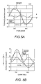
- the results of the analysis are shown in Figures 5A and 5B shows diagrams comparing the piston acceleration characteristics for a multi-link engine to a single-link engine.
- Figure 5A is a plot of piston acceleration characteristic curves versus the crank angle for a multi-link engine.
- Figure 5B is a plot of piston acceleration characteristic curves versus the crank angle for a single-link engine as a comparative example. This is a comparison with a common single-link engine in which the ratio of the connecting rod length to the stroke is about 1.5 to 3.
- the magnitude (absolute value) of the overall piston acceleration obtained by combining a first order component and a second order component is small in a vicinity of bottom dead center than in a vicinity of top dead center.
- the magnitude (absolute value) of the overall piston acceleration is substantially the same at both bottom dead center and top dead center.
- the magnitude of the second order component is smaller in the case of the multi-link engine than in the case of the single-link engine. Therefore, a characteristic of the multi-link engine is that second-order vibration can be reduced.
- Figure 7 is a perspective view of the vicinity of the piston, with the cylinder liner is depicted by the single-dotted line. The piston 32 is lowered at this time to a position where the remaining piston skirt 32a is lower than the topmost part 31 b of the bottom end of the cylinder liner.
- the cutouts 31b and 31 c are formed in this manner, the cylinder liner remainder part 31 d has lower strength. Furthermore, the surface pressure applied to the cylinder liner remainder part 31 d increases in proportion to the decrease in the surface area of the cylinder liner remainder part 31 d (decrease in the equivalent piston skirt).
- the illustrated embodiment is designed so that the axis of the upper link 11 (an imaginary straight line that joins a center of the piston pin 21 with a center of the upper link pin 22) and the axis of the cylinder are made parallel at this time.
- the angle formed by the axis of the upper link 11 and the axis of the cylinder is kept at zero degrees, which is the minimum amount, when the crank angle is within a range where the bottom end of the piston skirt 32a is positioned below the topmost part 31 b of the bottom end of the cylinder liner 31 a, as shown in Figure 6D . Therefore, the thrust force applied from the piston 32 to the cylinder liner 31 a is small, and deformation of the cylinder liner 31 a can be effectively suppressed even if cutouts 31 b and 31 c are formed in the cylinder liner 31 a.
- the thrust force applied from the piston 32 to the cylinder liner 31 a is at a minimum when the angle formed by the axis of the upper link 11 and the axis of the cylinder is at a minimum, as seen from the crank axial direction.
- the result of such a state is that no deformation occurs in the cylinder liner 31 a even if cutouts are formed in the cylinder liner 31 a.
- the curvature radius of the movement locus of the axial center of the upper link pin 22 is smaller in the vicinity of the piston bottom dead center than in the vicinity of the piston top dead center, as shown in Figure 6D .
- the distance L1 from straight line A to straight line C is less than the distance L2 from straight line B to straight line C, where A is a straight line orthogonal to the cylinder axis and tangent to an area in the vicinity of the top end of the elliptical axial locus of the upper link pin 22, B is a straight line orthogonal to the cylinder axis and tangent to an area in the vicinity of the bottom end of the elliptical locus, and C is a straight line which intersects the elliptical locus at two points, which is orthogonal to the cylinder axis, and along which the distance between the two points of intersection reaches a maximum.
- the axial center of the upper link pin 22 is positioned below the straight line D that joins the axial center of the control link pin 23 and the axial center of the crank pins 33b. If the axial center of the upper link pin 22, the axial center of the control link pin 23, and the axial center of the crank pins 33b all lie along one straight line, the axial center of the upper link pin 22 is positioned on the straight line D that joins the axial center of the control link pin 23 and the axial center of the crank pins 33b.
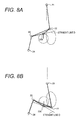
- a case is herein considered in which the axial center of the upper link pin 22 is positioned above the straight line D that joins the axial center of the control link pin 23 and the axial center of the crank pins 33b, as shown in the comparative example in Figure 8 .
- the position of the upper link pin 22 is higher than in the case shown in Figure 6 , regardless of whether the piston 32 is in the vicinity of the top dead center ( Figure 8A ) or in the vicinity of the bottom dead center ( Figure 8B ). Therefore, positioning the axial center of the upper link pin 22 below the straight line D makes it easier to lengthen the stroke without increasing the top deck height (overall height).
- the compression ratio can be mechanically adjusted.
- the geometry is set at this time so that the minimum angle formed by the axis of the upper link 11 and the cylinder axis is smaller at a low compression ratio than at a high compression ratio.
- the solid lines indicate a low compression ratio
- the dashed lines indicate a high compression ratio. Under high load conditions, it is advantageous to set the compression ratio low in accordance with the operating conditions in order to ensure the desired output.
- the multi-link engine 1 is a variable compression ratio engine
- the point where the minimum angle formed between the upper link axis of the upper link 11 and the cylinder axis can vary depending on the position of the eccentric position of the control shaft 24.
- the minimum angle formed between the upper link axis of the upper link and the cylinder axis can occur within a prescribed ranged that includes when the piston 32 is at bottom dead center, when the piston 32 is just before bottom dead center and when the piston 32 is just after bottom dead center.
- Figures 9A and 9B diagrammatically illustrate a link geometry of a multi-link engine according to a second embodiment.
- the first embodiment described above was designed so that the axial center of the upper link pin 22 was positioned below a straight line D that joins the axial center of the control link pin 23 and the axial center of the crank pins 33b.
- the second embodiment is designed so that the axial center of the upper link pin 22, the axial center of the control link pin 23, and the axial center of the crank pins 33b are disposed along one straight line, and the axial center of the upper link pin 22 is positioned above the straight line D that joins the axial center of the control link pin 23 and the axial center of the crank pins 33b.
- the position of the upper link pin 22 can be lowered regardless of whether the piston 32 is in the vicinity of the top dead center or in the vicinity of the bottom dead center, in comparison with the comparative example in Figures 8A and 8B . Therefore, even if the axial center of the upper link pin 22 is positioned on the straight line D, the stroke can be lengthened without increasing the top deck height (overall height).
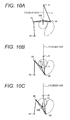
- Figure 10 diagrammatically illustrate a link geometry of a multi-link engine according to a third embodiment.
- the movement locus of the axial center of the upper link pin 22 was aligned with the cylinder axis.
- the third embodiment is a case in which the movement locus of the axial center of the upper link pin 22 is in a position displaced from the cylinder axis.
- the movement locus of the axial center of the upper link pin 22 has a shape inclined to the right, as shown in Figures 10A to 10C .
- the axial center of the upper link pin 22 reaches the left end of the movement locus while the piston is moving from the top dead center ( Figure 10A ) to the bottom dead center ( Figure 10C ), at which time the angle formed by the axis of the upper link 11 and the cylinder axis reaches a minimum ( Figure 10B ).
- the bottom end of the piston skirt is positioned below the topmost part 31 b of the bottom end of the cylinder liner 31 a at this time.
- the illustrated embodiment is designed so that at the time when the angle formed by the axis of the upper link 11 and the cylinder axis reaches a minimum, the bottom end of the piston skirt is positioned below the topmost part 31 b of the bottom end of the cylinder liner 31 a. Therefore, the thrust force applied from the piston 32 to the cylinder liner 31 a can be reduced even in cases in which the movement locus of the axial center of the upper link pin 22 is in a position that is offset from the cylinder axis, and no deformation occurs in the cylinder liner 31 a even if cutouts are formed in the cylinder liner 31 a.
- the control shaft 24 as an eccentric shaft and moving the position of the eccentric position of the control shaft 24 with respect to the pivot axis of the control shaft 24, the oscillation or rocking center of the control link 13, and the top dead center position of the piston 32 can be changed. In this way, the compression ratio can be mechanically adjusted.
- the minimum angle formed by the axis of the upper link 11 and the cylinder axis at this time is less at a low compression ratio than at a high compression ratio.
- the shape of the cylinder liner shown in Figure 4 is merely one example, and the cylinder may, for example, be shaped as shown in Figure 11 .
- the position of the bottom end of the cylinder liner in the direction of the cylinder axis can be formed so as to not be constant and so that at least one part of the bottom end has different positions.
- the bottom end of the piston skirt is positioned below the topmost part of the bottom end of the cylinder liner 31 a at the time when the angle formed by the axis of the upper link 11 and the axis of the cylinder reaches a minimum, as seen from the crank axis direction.
- the timing when the bottom end of the piston skirt is positioned below the topmost part of the bottom end of the cylinder liner 41 a is the timing when the angle formed by the axis of the upper link 11 and the axis of the cylinder reaches a minimum as seen from the crank axis direction, deformation of the cylinder liner 41 a can be effectively suppressed even if the bottom end position of the cylinder liner 41 a is formed so that the positions is not constant and at least one part of the bottom end has different positions.
- the term “comprising” and its derivatives, as used herein, are intended to be open ended terms that specify the presence of the stated features, elements, components, groups, integers, and/or steps, but do not exclude the presence of other unstated features, elements, components, groups, integers and/or steps.
- the foregoing also applies to words having similar meanings such as the terms, “including”, “having” and their derivatives.
- the terms “part,” “section,” “portion,” “member” or “element” when used in the singular can have the dual meaning of a single part or a plurality of parts.
- the terms of degree such as “substantially”, “about” and “approximately” as used herein mean a reasonable amount of deviation of the modified term such that the end result is not significantly changed.
Abstract
Description
- The present invention generally relates to a multi-link engine and particularly, but not exclusively, to a link geometry for a multi-link engine. Aspects of the invention relate to an apparatus, to an engine and to a vehicle.
- Engines have been developed in which a piston pin and a crank pin are connected by a plurality of links (such engines are hereinafter called multi-link engines). For example, a multi-link engine is disclosed in Japanese Laid-Open Patent Publication No.
2002-61501 - An engine in which the piston and crankshaft are connected by single link (i.e., a connecting rod) is a common engine that is referred to hereinafter as a "single-link engine" in contrast to a multi-link engine. A distinctive characteristic of a multi-link engine is that it enables a long stroke to be obtained without increasing the top deck height (overall height), which is not possible in an engine having one link (i.e., connecting rod) connected between the piston and the crank shaft (an engine with one link is a normal engine but hereinafter will be referred to as a "single-link engine"). Technologies utilizing this characteristic are being researched, such as in Japanese Laid-Open Patent Publication No.
2006-183595 - In Japanese Laid-Open Patent Application No.
2006-183595 2001-227367 2005-147068 - It has been discovered that when a cutout is formed in the bottom end of the cylinder liner as described above, the rigidity of the cylinder liner is weakened in the vicinity of the cutout. Meanwhile, the surface pressure applied to the cylinder liner is higher in the vicinity of the cutout because the surface area of the cylinder liner is smaller in the vicinity of the cutout. Consequently, there is the possibility that the cylinder liner will undergo deformation or the contact state between the cylinder liner and the piston skirt will be degraded when the piston experiences a large thrust load. Also, when the piston experiences a large thrust load, there is the possibility that an edge of the cutout of the cylinder liner will cause a film of lubricating oil on the piston skirt to be scraped off.
- It is an aim of the present invention to address this issue and to improve upon known technology. Embodiments of the invention may provide a link geometry for a multi-link engine that prevents deformation of the cylinder liner from occurring even when the rigidity of the cylinder liner has been weakened by removing a portion of the bottom end of the cylinder liner. Other aims and advantages of the invention will become apparent from the following description, claims and drawings.
- Aspects of the invention therefore provide an apparatus, an engine and a vehicle as claimed in the appended claims.
- According to another aspect of the invention for which protection is sought, there is provided a multi-link engine comprising an engine block body including at least one cylinder with a cylinder liner formed so that a bottom end position in the direction of a cylinder axis is not constant and at least part of the bottom end has different positions, a crankshaft including a crank pin, a piston operatively coupled to the crankshaft to reciprocally move inside the cylinder of the engine, an upper link rotatably connected to the piston by a piston pin, a lower link rotatably connected to the crank pin of the crankshaft and rotatably connected to the upper link by an upper link pin and a control link rotatably connected at one end to the lower link by a control link pin and rotatably connected at another end to the engine block body by a control shaft, the upper link having an upper link axis that forms an angle with the cylinder axis, as viewed along a crank axis direction of the crankshaft, such that the angle reaches a minimum angle when a crank angle of the engine is within a range where the bottom end of a piston skirt is positioned below a topmost part of the bottom end of the cylinder liner.
- In an embodiment, the upper link axis is parallel with the cylinder axis, as seen from the crank axis direction, when the angle formed by the upper link axis and the cylinder axis reaches the minimum angle, as seen from the crank axis direction.
- In an embodiment, the curvature radius of a movement locus of an axial center of the upper link pin is less in a vicinity of a bottom dead center of the piston than in the vicinity of a top dead center of the piston.
- In an embodiment, the upper link is configured such that a distance from a first straight line to a second straight line is less than a distance from a third straight line to the second straight line, where the first straight line is orthogonal to the cylinder axis and tangent to an area in the vicinity of a top end of an elliptical axial center locus of the upper link pin, the second straight line is orthogonal to the cylinder axis and tangent to an area in a vicinity of the bottom end of the elliptical locus and the third straight line intersects the elliptical locus at two points, and is orthogonal to the cylinder axis, in which a distance between the two points of intersection reaches a maximum.
- In an embodiment, an axial center of the upper link pin is positioned on or below a straight line that joins an axial center of the control link pin and an axial center of the crank pin.
- In an embodiment, the upper link, the lower link and the control link are arranged with respect to each other such that a size of a relative maximum value of a reciprocal motion acceleration of the piston when the piston is near bottom dead center is equal to or larger than a size of a relative maximum value of a reciprocal motion acceleration of the piston when the piston is near top dead center.
- In an embodiment, the multi-link engine is a variable compression ratio engine configured such that a compression ratio thereof can be changed in accordance with an operating condition by adjusting a position of an eccentric pin of the control shaft, with the minimum angle being set to a smaller angle at a low compression ratio than at a high compression ratio.
- In an embodiment, the minimum angle formed between the upper link axis of the upper link and the cylinder axis occurs when the piston is at bottom dead center.
- In an embodiment, the minimum angle formed between the upper link axis of the upper link and the cylinder axis occurs when the piston is before bottom dead center.
- In an embodiment, the minimum angle formed between the upper link axis of the upper link and the cylinder axis occurs when the piston is after bottom dead center.
- For example, in embodiments of the invention, a multi-link engine is provided that comprises an engine block body, a crankshaft, a piston, an upper link, a lower link and a control link. The engine block body includes at least one cylinder with a cylinder liner formed so that a bottom end position in the direction of a cylinder axis is not constant and at least part of the bottom end has different positions. The crankshaft includes a crank pin. The piston is operatively coupled to the crankshaft to reciprocally move inside the cylinder of the engine. The upper link is rotatably connected to the piston by a piston pin. The lower link is rotatably connected to the crank pin of the crankshaft and is rotatably connected to the upper link by an upper link pin. The control link is rotatably connected at one end to the lower link by a control link pin and rotatably connected at another end to the engine block body by a control shaft. The upper link has an upper link axis that forms an angle with the cylinder axis, as viewed along a crank axis direction of the crankshaft, such that the angle reaches a minimum when a crank angle of the engine is within a range where the bottom end of a piston skirt is positioned below a topmost part of the bottom end of the cylinder liner.
- Within the scope of this application, it is envisaged that the various aspects, embodiments, examples, features and alternatives set out in the preceding paragraphs, in the claims and/or in the following description and drawings may be taken individually or in any combination thereof.
- The present invention will now be described, by way of example only, with reference to the accompanying drawings, in which:
-
Figure 1 is a vertical cross sectional view of a multi-link engine in accordance with one embodiment; -
Figure 2A is a partial perspective view of a piston of the multi-link engine illustrated inFigure 1 ; -
Figure 2B is a cross sectional view of the piston illustrated inFigure 2A as seen alongsection line 2B-2B ofFigure 2A ; -
Figure 2C is a cross sectional view of the piston illustrated inFigure 2A as seen alongsection line 2C-2C ofFigure 2A ; -
Figure 3A is a diagrammatic view of the piston to illustrate the behavior of the piston; -
Figure 3B is a diagrammatic view of the piston to illustrate the behavior of the piston; -
Figure 4A is a longitudinal cross sectional view of a cylinder liner for the multi-link engine illustrated inFigure 1 showing a left-hand internal surface of the cylinder liner as viewed from the center axis of the cylinder; -
Figure 4B is a longitudinal cross sectional view of the cylinder liner for the multi-link engine illustrated inFigure 1 showing a right-hand internal surface of the cylinder liner as viewed from the center axis of the cylinder; -
Figure 5A is a graph that plots the piston acceleration versus the crank angle for explaining a piston acceleration characteristic of a variable compression ratio (VCR) multi-link engine; -
Figure 5B is a graph that plots the piston acceleration versus the crank angle for explaining a piston acceleration characteristic of a conventional single-link engine; -
Figure 6A is a longitudinal cross sectional view of the multi-link engine illustrated inFigure 1 where the piston is at top dead center; -
Figure 6B is a link diagram of the multi-link engine illustrated inFigure 6A where the piston is at top dead center; -
Figure 6C is a cross sectional view of the multi-link engine illustrated inFigure 1 where the piston is at bottom dead center; -
Figure 6D is a link diagram of the multi-link engine illustrated inFigure 6C where the piston is at bottom dead center; -
Figure 7 is a perspective view of selected parts of the multi-link engine in the vicinity of the piston, as viewed perpendicularly to the crankshaft from the left side of the crankshaft as seen inFigure 6C ; -
Figure 8A is a link diagram of a comparative example where the piston is at top dead center; -
Figure 8B is a link diagram of a comparative example where the piston is at bottom dead center; -
Figure 9A is a link diagram of a multi-link engine in accordance with a second embodiment of a link geometry where the piston is at top dead center; -
Figure 9B is a link diagram of the multi-link engine in accordance with the second embodiment of the link geometry where the piston is at bottom dead center; -
Figure 10A is a link diagram of a multi-link engine in accordance with a third embodiment of a link geometry where the piston is at top dead center; -
Figure 10B is a link diagram of the multi-link engine in accordance with the third embodiment of the link geometry where the piston is at bottom dead center; -
Figure 10C is a link diagram of the multi-link engine in accordance with the third embodiment of the link geometry where the piston is at bottom dead center with the position of the control shaft changed; -
Figure 11A is a longitudinal cross sectional view of another center liner for a multi-link engine illustrated inFigure 1 showing a left-hand internal surface of the cylinder liner as viewed from the center axis of the cylinder; and -
Figure 11B is a longitudinal cross sectional view of the center liner ofFigure 11 showing a right-hand internal surface of the cylinder liner as viewed from the center axis of the cylinder. - Selected embodiments of the present invention will now be explained with reference to the drawings. It will be apparent to those skilled in the art from this disclosure that the following descriptions of the embodiments of the present invention are provided for illustration only and not for the purpose of limiting the invention as defined by the appended claims and their equivalents.
- Referring initially to
Figure 1 , selected portions of amulti-link engine 10 is illustrated in accordance with an embodiment. Themulti-link engine 10 has a plurality of cylinder. However, only one cylinder will be illustrated herein for the sake of brevity. Themulti-link engine 10 includes, among other things, a linkage for each cylinder having anupper link 11, alower link 12 connected to theupper link 11 and acontrol link 13 connected to thelower link 12. Themulti-link engine 10 also includes apiston 32 for each cylinder and acrankshaft 33, which are connected by the upper andlower links - In
Figure 1 , thepiston 32 of the multi-link engine is illustrated at bottom dead center.Figure 1 is a cross sectional view taken along an axial direction of thecrankshaft 33 of theengine 10. Among those skilled in the engine field, it is customary to use the expressions "top dead center" and "bottom dead center" irrespective of the direction of gravity. In horizontally opposed engines (flat engine) and other similar engines, top dead center and bottom dead center do not necessarily correspond to the top and bottom of the engine, respectively, in terms of the direction of gravity. Furthermore, if the engine is inverted, it is possible for top dead center to correspond to the bottom or downward direction in terms of the direction of gravity and bottom dead center to correspond to the top or upward direction in terms of the direction of gravity. However, in this specification, common practice is observed and the direction corresponding to top dead center is referred to as the "upward direction" or "top" and the direction corresponding to bottom dead center is referred to as the "downward direction" or "bottom." - Now the linkage of the
multi-link engine 10, will be described in more detail. An upper end of theupper link 11 is connected to thepiston 32 by apiston pin 21, while a lower end of theupper link 11 is connected to one end of thelower link 12 by anupper link pin 22. Thepiston 32 moves reciprocally inside acylinder liner 31 a of acylinder block 31 in response to combustion pressure. In this embodiment, as shown inFigure 1 , theupper link 11 adopts an orientation substantially parallel to a center axis of thecylinder liner 31 a and a bottommost portion of thepiston 32 is positioned below a bottommost portion of a bottom end of thecylinder liner 31 a when thepiston 32 is at bottom dead center. - Referring
Figure 1 , thecrankshaft 33 is provided with a plurality of crankjournals 33a, a plurality of crank pins 33b and a plurality ofcounterweights 33c. The crankjournals 33a are rotatably supported by thecylinder block 31 and a ladder frame. Thecrank pin 33b for each cylinder is eccentric relative to the crankjournals 33a by a prescribed amount and thelower link 12 is rotatably connected to the crankpin 33b. Thelower link 12 has a bearing hole located in its approximate middle. Thecrank pin 33b of thecrankshaft 33 is disposed in the bearing hole of thelower link 12 such that thelower link 12 rotates about thecrank pin 33b. Thelower link 12 is constructed such that it can be divided into a left member and a right member (two members). One end of thelower link 12 is connected to theupper link 11 with theupper link pin 22 and the other end of thelower link 12 is connected to thecontrol link 13 with acontrol link pin 23. - The
piston 32 will be described herein with reference toFigures 2A to 3B . Thepiston 32 is designed so that apiston skirt 32a remains in the lengthwise center portion of thepiston pin 21, but there is no piston skirt on the sides of thepiston pin 21, as shown inFigure 2C . According to this structure of thepiston 32, thecounterweights 33c passes on the sides of the piston pin 21 (thepiston skirt 32a) when thepiston 32 is at the bottom dead center as shown inFigure 3A . Therefore, the length of theupper link 11 is minimized and the bottom dead center position of thepiston 32 is brought as close as possible to thecrankshaft 33, whereby the piston stroke can be enlarged proportionately. The side thrust force created by the tilt of theupper link 11 is primarily borne by the remainingpiston skirt 32a. - Next, the
cylinder liner 31 a will be described with reference toFigures 4A and 4B .
Figure 4A is a longitudinal cross-sectional view of the left inside surface of thecylinder liner 31 a, as seen from the cylinder axis.Figure 4B is a longitudinal cross-sectional view of the right inside surface of thecylinder liner 31 a, as seen from the cylinder axis. - As can be determined from
Figure 1 , thecrankshaft 33 and thelower link 12 pass through in the vicinity of the bottom end of thecylinder liner 31 a on the left side inFigure 1 . Therefore, acutout 31 b is formed in the bottom end of thecylinder liner 31 a on the left inner side for allowing thecounterweight 33c of thecrankshaft 33 to pass through, as shown inFigure 4A . Also acutout 31 c is formed in the bottom end of thecylinder liner 31 a on the left inner side for allowing thelower link 12 to pass through, as shown inFigure 4A . Therefore, the position of the bottom end of thecylinder liner 31 a in the axial direction of the cylinder is variable rather than constant. In the illustrated embodiment, thecutout 31 b is formed deeper than thecutout 31 c, and thecutout 31 b is level with the highest part of the bottom end of thecylinder liner 31 a. The remaining portions of thecutout 31 b and thecutout 31 c constitute aremainder part 31 d. - The
upper link 11 passes through the vicinity of the bottom end of thecylinder liner 31 a on the right side inFigure 1 . Therefore, acutout 31 e is formed in the bottom end of the right inner side of thecylinder liner 31 a for allowing theupper link 11 to pass through, as shown inFigure 4B . The position of the bottom end of thecylinder liner 31 a in the axial direction of the cylinder is therefore variable rather than constant. - Returning to
Figure 1 , thecontrol link pin 23 is inserted through the distal end of thecontrol link 13, which is turnably connected to thelower link 12. The control link 13 is connected at the other end to thecylinder block 31 via acontrol shaft 24. The control link 13 oscillates around thecontrol shaft 24. Part of thecontrol shaft 24 is made to be eccentric, and the eccentric position of thecontrol shaft 24 is moved as an eccentric axis, thereby changing the oscillation or rocking center of thecontrol link 13 and the top dead center position of thepiston 32, as shown in the drawing. It is thereby possible to mechanically adjust the compression ratio of the engine. - According to analysis, a multi-link engine can be made to have a lower degree of vibration than a single-link engine by adjusting the position of the control shaft appropriately. The results of the analysis are shown in
Figures 5A and 5B shows diagrams comparing the piston acceleration characteristics for a multi-link engine to a single-link engine.Figure 5A is a plot of piston acceleration characteristic curves versus the crank angle for a multi-link engine.Figure 5B is a plot of piston acceleration characteristic curves versus the crank angle for a single-link engine as a comparative example. This is a comparison with a common single-link engine in which the ratio of the connecting rod length to the stroke is about 1.5 to 3. Assuming the upper link of the multi-link engine is equivalent to the connecting rod of the single-link engine, the comparison is made under the conditions that the stroke lengths are the same and that the upper link of the multi-link engine has the same length as the connecting rod of the single-link engine. - As shown in
Figure 5B , with the single-link engine, the magnitude (absolute value) of the overall piston acceleration obtained by combining a first order component and a second order component is small in a vicinity of bottom dead center than in a vicinity of top dead center. Conversely, as shown inFigure 5A , with the multi-link engine the magnitude (absolute value) of the overall piston acceleration is substantially the same at both bottom dead center and top dead center. Additionally, the magnitude of the second order component is smaller in the case of the multi-link engine than in the case of the single-link engine. Therefore, a characteristic of the multi-link engine is that second-order vibration can be reduced. - Next, referring to
Figure 6 , the link geometry of the multi-link engine of the illustrated embodiment will be described in further detail. The substantially elliptical shapes indicated by the single-dotted lines inFigures 6B and 6D are the movement loci of the axis of theupper link pin 22. - In the illustrated embodiment, when the
piston 32 is at the bottom dead center as shown inFigure 6C , the bottom end of thepiston skirt 32a is positioned below thetopmost part 31 b of the bottom end of thecylinder liner 31 a. The positional relationship between the cylinder bore and thepiston 32 in the vicinity of the bottom dead center at this time is shown inFigure 7. Figure 7 is a perspective view of the vicinity of the piston, with the cylinder liner is depicted by the single-dotted line. Thepiston 32 is lowered at this time to a position where the remainingpiston skirt 32a is lower than thetopmost part 31 b of the bottom end of the cylinder liner. Formed in the bottom part of thecylinder liner 31a are thecutouts 31b for allowing thecounterweights 33c of thecrankshaft 33 to pass through, and thecutout 31c for allowing thelower link 12 to pass through, as described above. Since thecutouts liner remainder part 31 d has lower strength. Furthermore, the surface pressure applied to the cylinderliner remainder part 31 d increases in proportion to the decrease in the surface area of the cylinderliner remainder part 31 d (decrease in the equivalent piston skirt). Therefore, when the thrust load of thepiston 32 is considerable, there is a possibility that the cylinder liner (remainder part 31 d) will deform and that the state of contact between thecylinder liner 31 a and thepiston skirt 32a will be compromised. Also, when the thrust load of thepiston 32 is considerable, there is a possibility that the lubricating oil film on thepiston skirt 32a will be scraped off by the edges of thecutouts 31 b and31c of thecylinder liner 31 a. In view of this, the illustrated embodiment is designed so that the axis of the upper link 11 (an imaginary straight line that joins a center of thepiston pin 21 with a center of the upper link pin 22) and the axis of the cylinder are made parallel at this time. That is to say, the angle formed by the axis of theupper link 11 and the axis of the cylinder is kept at zero degrees, which is the minimum amount, when the crank angle is within a range where the bottom end of thepiston skirt 32a is positioned below thetopmost part 31 b of the bottom end of thecylinder liner 31 a, as shown inFigure 6D . Therefore, the thrust force applied from thepiston 32 to thecylinder liner 31 a is small, and deformation of thecylinder liner 31 a can be effectively suppressed even ifcutouts cylinder liner 31 a. Particularly, the thrust force applied from thepiston 32 to thecylinder liner 31 a is at a minimum when the angle formed by the axis of theupper link 11 and the axis of the cylinder is at a minimum, as seen from the crank axial direction. When the bottom end of the piston skirt is positioned below thetopmost part 31 b of the bottom end of thecylinder liner 31 a, the result of such a state is that no deformation occurs in thecylinder liner 31 a even if cutouts are formed in thecylinder liner 31 a. When thepiston 32 is at the bottom dead center, the bottommost part of thepiston 32 is positioned below the bottommost part of the bottom end of thecylinder liner 31 a, but since the thrust force applied from thepiston 32 to thecylinder liner 31a is small, it is possible to prevent the lubricating oil film on the piston skirt from being scraped off by the edges of the cutouts in thecylinder liner 31 a. - The curvature radius of the movement locus of the axial center of the
upper link pin 22 is smaller in the vicinity of the piston bottom dead center than in the vicinity of the piston top dead center, as shown inFigure 6D . In other words, the distance L1 from straight line A to straight line C is less than the distance L2 from straight line B to straight line C, where A is a straight line orthogonal to the cylinder axis and tangent to an area in the vicinity of the top end of the elliptical axial locus of theupper link pin 22, B is a straight line orthogonal to the cylinder axis and tangent to an area in the vicinity of the bottom end of the elliptical locus, and C is a straight line which intersects the elliptical locus at two points, which is orthogonal to the cylinder axis, and along which the distance between the two points of intersection reaches a maximum. - The axial center of the
upper link pin 22 is positioned below the straight line D that joins the axial center of thecontrol link pin 23 and the axial center of the crank pins 33b. If the axial center of theupper link pin 22, the axial center of thecontrol link pin 23, and the axial center of the crank pins 33b all lie along one straight line, the axial center of theupper link pin 22 is positioned on the straight line D that joins the axial center of thecontrol link pin 23 and the axial center of the crank pins 33b. - A case is herein considered in which the axial center of the
upper link pin 22 is positioned above the straight line D that joins the axial center of thecontrol link pin 23 and the axial center of the crank pins 33b, as shown in the comparative example inFigure 8 . When thecontrol shaft 24 is positioned to the lower left of the crankshaft center, and the control link pin is positioned to the left of the crank axial center (when the cylinder center line is positioned vertically in the drawing), the position of theupper link pin 22 is higher than in the case shown inFigure 6 , regardless of whether thepiston 32 is in the vicinity of the top dead center (Figure 8A ) or in the vicinity of the bottom dead center (Figure 8B ). Therefore, positioning the axial center of theupper link pin 22 below the straight line D makes it easier to lengthen the stroke without increasing the top deck height (overall height). - As described above, by making the
control shaft 24 as an eccentric shaft and moving the position of the eccentric position of thecontrol shaft 24 with respect to the pivot axis of thecontrol shaft 24, the oscillation or rocking center of thecontrol link 13, and thus, the top dead center position of thepiston 32 can be changed. In this way, the compression ratio can be mechanically adjusted. The geometry is set at this time so that the minimum angle formed by the axis of theupper link 11 and the cylinder axis is smaller at a low compression ratio than at a high compression ratio. InFigure 6D , the solid lines indicate a low compression ratio, and the dashed lines indicate a high compression ratio. Under high load conditions, it is advantageous to set the compression ratio low in accordance with the operating conditions in order to ensure the desired output. Under low load conditions, it is advantageous to set the compression ratio high so that exhaust loss is reduced by increasing expansion work. In cases in which the compression ratio is set in this manner, combustion pressure is increased and the side thrust force is greater during low load conditions. According to the illustrated embodiment, deformation of thecylinder liner 31a can be more effectively suppressed even in these cases. - Moreover, since the multi-link engine 1 is a variable compression ratio engine, the point where the minimum angle formed between the upper link axis of the
upper link 11 and the cylinder axis can vary depending on the position of the eccentric position of thecontrol shaft 24. Thus, the minimum angle formed between the upper link axis of the upper link and the cylinder axis can occur within a prescribed ranged that includes when thepiston 32 is at bottom dead center, when thepiston 32 is just before bottom dead center and when thepiston 32 is just after bottom dead center. -
Figures 9A and 9B diagrammatically illustrate a link geometry of a multi-link engine according to a second embodiment. The first embodiment described above was designed so that the axial center of theupper link pin 22 was positioned below a straight line D that joins the axial center of thecontrol link pin 23 and the axial center of the crank pins 33b. On the other hand, the second embodiment is designed so that the axial center of theupper link pin 22, the axial center of thecontrol link pin 23, and the axial center of the crank pins 33b are disposed along one straight line, and the axial center of theupper link pin 22 is positioned above the straight line D that joins the axial center of thecontrol link pin 23 and the axial center of the crank pins 33b. Thus, the position of theupper link pin 22 can be lowered regardless of whether thepiston 32 is in the vicinity of the top dead center or in the vicinity of the bottom dead center, in comparison with the comparative example inFigures 8A and 8B . Therefore, even if the axial center of theupper link pin 22 is positioned on the straight line D, the stroke can be lengthened without increasing the top deck height (overall height). -
Figure 10 diagrammatically illustrate a link geometry of a multi-link engine according to a third embodiment. In the first embodiment described above, the movement locus of the axial center of theupper link pin 22 was aligned with the cylinder axis. On the other hand, the third embodiment is a case in which the movement locus of the axial center of theupper link pin 22 is in a position displaced from the cylinder axis. - In this case, the movement locus of the axial center of the
upper link pin 22 has a shape inclined to the right, as shown inFigures 10A to 10C . The axial center of theupper link pin 22 reaches the left end of the movement locus while the piston is moving from the top dead center (Figure 10A ) to the bottom dead center (Figure 10C ), at which time the angle formed by the axis of theupper link 11 and the cylinder axis reaches a minimum (Figure 10B ). In the illustrated embodiment, the bottom end of the piston skirt is positioned below thetopmost part 31 b of the bottom end of thecylinder liner 31 a at this time. - Thus, the illustrated embodiment is designed so that at the time when the angle formed by the axis of the
upper link 11 and the cylinder axis reaches a minimum, the bottom end of the piston skirt is positioned below thetopmost part 31 b of the bottom end of thecylinder liner 31 a. Therefore, the thrust force applied from thepiston 32 to thecylinder liner 31 a can be reduced even in cases in which the movement locus of the axial center of theupper link pin 22 is in a position that is offset from the cylinder axis, and no deformation occurs in thecylinder liner 31 a even if cutouts are formed in thecylinder liner 31 a. - As described above, by making the
control shaft 24 as an eccentric shaft and moving the position of the eccentric position of thecontrol shaft 24 with respect to the pivot axis of thecontrol shaft 24, the oscillation or rocking center of thecontrol link 13, and the top dead center position of thepiston 32 can be changed. In this way, the compression ratio can be mechanically adjusted. The minimum angle formed by the axis of theupper link 11 and the cylinder axis at this time is less at a low compression ratio than at a high compression ratio. - The shape of the cylinder liner shown in
Figure 4 is merely one example, and the cylinder may, for example, be shaped as shown inFigure 11 . In other words, the position of the bottom end of the cylinder liner in the direction of the cylinder axis can be formed so as to not be constant and so that at least one part of the bottom end has different positions. - According to the illustrated embodiments, the bottom end of the piston skirt is positioned below the topmost part of the bottom end of the
cylinder liner 31 a at the time when the angle formed by the axis of theupper link 11 and the axis of the cylinder reaches a minimum, as seen from the crank axis direction. In other words, since the timing when the bottom end of the piston skirt is positioned below the topmost part of the bottom end of the cylinder liner 41 a is the timing when the angle formed by the axis of theupper link 11 and the axis of the cylinder reaches a minimum as seen from the crank axis direction, deformation of the cylinder liner 41 a can be effectively suppressed even if the bottom end position of the cylinder liner 41 a is formed so that the positions is not constant and at least one part of the bottom end has different positions. - In understanding the scope of the present invention, the term "comprising" and its derivatives, as used herein, are intended to be open ended terms that specify the presence of the stated features, elements, components, groups, integers, and/or steps, but do not exclude the presence of other unstated features, elements, components, groups, integers and/or steps. The foregoing also applies to words having similar meanings such as the terms, "including", "having" and their derivatives. Also, the terms "part," "section," "portion," "member" or "element" when used in the singular can have the dual meaning of a single part or a plurality of parts. The terms of degree such as "substantially", "about" and "approximately" as used herein mean a reasonable amount of deviation of the modified term such that the end result is not significantly changed.
- While only selected embodiments have been chosen to illustrate the present invention, it will be apparent to those skilled in the art from this disclosure that various changes and modifications can be made herein without departing from the scope of the invention as defined in the appended claims. For example, the size, shape, location or orientation of the various components can be changed as needed and/or desired. Components that are shown directly connected or contacting each other can have intermediate structures disposed between them. The functions of one element can be performed by two, and vice versa. The structures and functions of one embodiment can be adopted in another embodiment. It is not necessary for all advantages to be present in a particular embodiment at the same time. Every feature which is unique from the prior art, alone or in combination with other features, also should be considered a separate description of further inventions by the applicant, including the structural and/or functional concepts embodied by such feature(s). Thus, the foregoing descriptions of the embodiments according to the present invention are provided for illustration only, and not for the purpose of limiting the invention as defined by the appended claims and their equivalents.
- This application claims priority from Japanese Patent Application Nos.
2007-279395 2007-279401 2007-281459 2008-161633, filed 20th June 2008
Claims (12)
- An apparatus for an engine having an engine block body including at least one cylinder with a cylinder liner formed so that a bottom end position in the direction of a cylinder axis is not constant and at least part of the bottom end has different positions, a crankshaft including a crank pin and a piston operatively coupled to the crankshaft to reciprocally move inside the cylinder of the engine, the apparatus comprising:an upper link rotatably connected to the piston by a piston pin;a lower link rotatably connected to the crank pin of the crankshaft and rotatably connected to the upper link by an upper link pin; anda control link rotatably connected at one end to the lower link by a control link pin and rotatably connected at another end to the engine block body by a control shaft;where the bottom end of a piston skirt is positioned below a topmost part of the bottom end of the cylinder liner.
wherein the upper link has an upper link axis that forms an angle with the cylinder axis, as viewed along a crank axis direction of the crankshaft, such that the angle reaches a minimum angle when a crank angle of the engine is within a range - An apparatus as claimed in claim 1, wherein the upper link axis is parallel with the cylinder axis, as seen from the crank axis direction, when the angle formed by the upper link axis and the cylinder axis reaches the minimum angle, as seen from the crank axis direction.
- An apparatus as claimed in claim 1 or claim 2, wherein the curvature radius of a movement locus of an axial center of the upper link pin is less in a vicinity of a bottom dead center of the piston than in the vicinity of a top dead center of the piston.
- An apparatus as claimed in any preceding claim, wherein the upper link is configured such that a distance from a first straight line to a second straight line is less than a distance from a third straight line to the second straight line;
where the first straight line is orthogonal to the cylinder axis and tangent to an area in the vicinity of a top end of an elliptical axial center locus of the upper link pin;the second straight line is orthogonal to the cylinder axis and tangent to an area in a vicinity of the bottom end of the elliptical locus; andthe third straight line intersects the elliptical locus at two points, and is orthogonal to the cylinder axis, in which a distance between the two points of intersection reaches a maximum. - An apparatus as claimed in any preceding claim, wherein an axial center of the upper link pin is positioned on or below a straight line that joins an axial center of the control link pin and an axial center of the crank pin.
- An apparatus as claimed in any preceding claim, wherein the upper link, the lower link and the control link are arranged with respect to each other such that a size of a relative maximum value of a reciprocal motion acceleration of the piston when the piston is near bottom dead center is equal to or larger than a size of a relative maximum value of a reciprocal motion acceleration of the piston when the piston is near top dead center.
- An apparatus as claimed in any preceding claim, wherein the multi-link engine comprises a variable compression ratio engine configured such that a compression ratio thereof can be changed in accordance with an operating condition by adjusting a position of an eccentric pin of the control shaft, with the minimum angle being set to a smaller angle at a low compression ratio than at a high compression ratio.
- An apparatus as claimed in any preceding claim, wherein the minimum angle formed between the upper link axis of the upper link and the cylinder axis occurs when the piston is at bottom dead center.
- An apparatus as claimed in any preceding claim, wherein the minimum angle formed between the upper link axis of the upper link and the cylinder axis occurs when the piston is before bottom dead center.
- An apparatus as claimed in any preceding claim, wherein the minimum angle formed between the upper link axis of the upper link and the cylinder axis occurs when the piston is after bottom dead center.
- An engine having an apparatus as claimed in any preceding claim.
- A vehicle having an apparatus or an engine as claimed in any preceding claim.
Applications Claiming Priority (4)
| Application Number | Priority Date | Filing Date | Title |
|---|---|---|---|
| JP2007279395A JP4941231B2 (en) | 2007-10-26 | 2007-10-26 | Multilink engine link geometry |
| JP2007279401A JP2009108708A (en) | 2007-10-26 | 2007-10-26 | Link geometry for multi-link engine |
| JP2007281459 | 2007-10-30 | ||
| JP2008161633A JP5056612B2 (en) | 2007-10-30 | 2008-06-20 | Multilink engine link geometry |
Publications (3)
| Publication Number | Publication Date |
|---|---|
| EP2053218A2 true EP2053218A2 (en) | 2009-04-29 |
| EP2053218A3 EP2053218A3 (en) | 2012-05-30 |
| EP2053218B1 EP2053218B1 (en) | 2015-04-22 |
Family
ID=40139241
Family Applications (3)
| Application Number | Title | Priority Date | Filing Date |
|---|---|---|---|
| EP08167434.3A Active EP2053217B1 (en) | 2007-10-26 | 2008-10-23 | Multi-Link Engine |
| EP08167433.5A Active EP2053216B1 (en) | 2007-10-26 | 2008-10-23 | Multi-link Engine |
| EP20080167435 Active EP2053218B1 (en) | 2007-10-26 | 2008-10-23 | Multi-Link Engine |
Family Applications Before (2)
| Application Number | Title | Priority Date | Filing Date |
|---|---|---|---|
| EP08167434.3A Active EP2053217B1 (en) | 2007-10-26 | 2008-10-23 | Multi-Link Engine |
| EP08167433.5A Active EP2053216B1 (en) | 2007-10-26 | 2008-10-23 | Multi-link Engine |
Country Status (2)
| Country | Link |
|---|---|
| US (3) | US8100097B2 (en) |
| EP (3) | EP2053217B1 (en) |
Cited By (2)
| Publication number | Priority date | Publication date | Assignee | Title |
|---|---|---|---|---|
| CN110657024A (en) * | 2018-12-30 | 2020-01-07 | 长城汽车股份有限公司 | Variable compression ratio mechanism and engine |
| CN110671199A (en) * | 2018-12-30 | 2020-01-10 | 长城汽车股份有限公司 | Variable compression ratio mechanism and engine |
Families Citing this family (19)
| Publication number | Priority date | Publication date | Assignee | Title |
|---|---|---|---|---|
| JP5146250B2 (en) * | 2008-10-20 | 2013-02-20 | 日産自動車株式会社 | Vibration reduction structure of multi-link engine |
| KR20130065438A (en) * | 2011-12-09 | 2013-06-19 | 현대자동차주식회사 | Two cylinder engine |
| DE102012008244B4 (en) * | 2012-04-25 | 2017-04-06 | Audi Ag | Multi-joint crank drive of an internal combustion engine |
| JP5949148B2 (en) * | 2012-05-23 | 2016-07-06 | 日産自動車株式会社 | Multi-link internal combustion engine |
| CN104813013B (en) * | 2012-11-30 | 2017-11-24 | 康明斯知识产权公司 | Engine cylinder and spacer assembly |
| CN105102798B (en) * | 2013-04-11 | 2018-06-22 | 日产自动车株式会社 | Internal combustion engine |
| CN105452605B (en) | 2013-05-20 | 2019-06-11 | 托马斯·史蒂夫·汉弗莱斯 | Fluid flow machine |
| US11557404B2 (en) | 2013-08-23 | 2023-01-17 | Global Energy Research Associates, LLC | Method of using nanofuel in a nanofuel internal engine |
| US9881706B2 (en) * | 2013-08-23 | 2018-01-30 | Global Energy Research Associates, LLC | Nuclear powered rotary internal engine apparatus |
| US9947423B2 (en) | 2013-08-23 | 2018-04-17 | Global Energy Research Associates, LLC | Nanofuel internal engine |
| US11450442B2 (en) | 2013-08-23 | 2022-09-20 | Global Energy Research Associates, LLC | Internal-external hybrid microreactor in a compact configuration |
| EP3040527B1 (en) * | 2013-08-27 | 2018-08-22 | Nissan Motor Co., Ltd | Multi-link piston-crank mechanism for internal combustion engine |
| DE102013019214B3 (en) * | 2013-11-14 | 2015-03-05 | Audi Ag | Multi-joint crank drive of an internal combustion engine and method for operating a multi-joint crank drive |
| CN104265451A (en) * | 2014-08-04 | 2015-01-07 | 朱譞晟 | Double-cylinder engine capable of evenly adjusting compression ratio and mechanical supercharging |
| CA2973535C (en) * | 2015-01-15 | 2018-01-23 | Nissan Motor Co., Ltd. | Double-link piston crank mechanism for internal combustion engine |
| US10215090B2 (en) | 2015-07-03 | 2019-02-26 | Board Of Regents, The University Of Texas System | Combustion engine linkage systems |
| US10690048B2 (en) * | 2015-09-16 | 2020-06-23 | Nissan Motor Co., Ltd. | Bolt fastening method for lower link |
| CN110671197B (en) * | 2018-12-29 | 2021-08-20 | 长城汽车股份有限公司 | Engine and vehicle with same |
| US11376662B2 (en) * | 2019-05-10 | 2022-07-05 | American Axle & Manufacturing, Inc. | Method for forming center link of connecting rod for variable displacement engine |
Citations (8)
| Publication number | Priority date | Publication date | Assignee | Title |
|---|---|---|---|---|
| JP2001227367A (en) | 2000-02-16 | 2001-08-24 | Nissan Motor Co Ltd | Reciprocating internal combustion engine |
| JP2002061501A (en) | 2000-08-17 | 2002-02-28 | Nissan Motor Co Ltd | Dual link mechanism for internal combustion engine |
| JP2005147068A (en) | 2003-11-19 | 2005-06-09 | Nissan Motor Co Ltd | Internal combustion engine |
| JP2006183595A (en) | 2004-12-28 | 2006-07-13 | Nissan Motor Co Ltd | Internal combustion engine |
| JP2007281459A (en) | 2006-04-06 | 2007-10-25 | Samsung Electronics Co Ltd | Thin film transistor indicating board and its manufacturing method |
| JP2007279395A (en) | 2006-04-06 | 2007-10-25 | Fujifilm Corp | Image illuminator, image display device and imaging apparatus |
| JP2007279401A (en) | 2006-04-07 | 2007-10-25 | Hitachi Ltd | Display device and panel module device |
| JP2008161633A (en) | 2006-12-28 | 2008-07-17 | Yasuyoshi Saito | Removal tool of coating of tongue |
Family Cites Families (26)
| Publication number | Priority date | Publication date | Assignee | Title |
|---|---|---|---|---|
| DE1072835B (en) * | 1960-01-07 | Courbevoie Seine Alfred Heid't (Frankreich) | Internal combustion engine | |
| US3693463A (en) * | 1970-08-03 | 1972-09-26 | Wilbur G Garman | Linkage for a reciprocating engine crankshaft |
| US4732115A (en) * | 1978-03-28 | 1988-03-22 | The Laitram Corporation | Interval spark ignition combustion engine |
| JPH09228858A (en) | 1996-02-24 | 1997-09-02 | Hondou Jutaku:Kk | Reciprocating engine |
| US5680840A (en) * | 1996-11-08 | 1997-10-28 | Mandella; Michael J. | Multi-crankshaft variable stroke engine |
| JP3991550B2 (en) | 2000-03-21 | 2007-10-17 | 日産自動車株式会社 | Internal combustion engine with variable compression ratio mechanism |
| JP3968967B2 (en) * | 2000-07-07 | 2007-08-29 | 日産自動車株式会社 | Variable compression ratio mechanism of reciprocating internal combustion engine |
| JP3861583B2 (en) * | 2000-08-14 | 2006-12-20 | 日産自動車株式会社 | Piston crank mechanism of internal combustion engine |
| JP3726678B2 (en) * | 2000-12-15 | 2005-12-14 | 日産自動車株式会社 | Crank mechanism of a multi-link reciprocating internal combustion engine |
| JP3882643B2 (en) * | 2001-04-05 | 2007-02-21 | 日産自動車株式会社 | Variable compression ratio mechanism of internal combustion engine |
| JP2003232233A (en) * | 2001-12-06 | 2003-08-22 | Nissan Motor Co Ltd | Control device of internal combustion engine |
| JP2003343297A (en) | 2002-03-20 | 2003-12-03 | Honda Motor Co Ltd | Engine |
| JP4300749B2 (en) * | 2002-05-09 | 2009-07-22 | 日産自動車株式会社 | Link mechanism of reciprocating internal combustion engine |
| JP4596726B2 (en) | 2002-07-30 | 2010-12-15 | 日産自動車株式会社 | Control device for internal combustion engine |
| JP4092474B2 (en) | 2002-11-07 | 2008-05-28 | 日産自動車株式会社 | COMPRESSION RATIO CONTROL DEVICE FOR INTERNAL COMBUSTION ENGINE |
| JP4285129B2 (en) | 2003-08-27 | 2009-06-24 | 日産自動車株式会社 | Variable compression ratio mechanism of internal combustion engine |
| JP4341392B2 (en) | 2003-12-05 | 2009-10-07 | 日産自動車株式会社 | Variable compression ratio device for internal combustion engine |
| JP4403885B2 (en) | 2004-06-04 | 2010-01-27 | 日産自動車株式会社 | Engine with multi-link piston crank mechanism |
| JP4581552B2 (en) | 2004-08-11 | 2010-11-17 | 日産自動車株式会社 | Reciprocating internal combustion engine |
| EP1659276B1 (en) * | 2004-11-18 | 2011-04-27 | Honda Motor Co., Ltd. | Variable stroke property engine |
| JP4334462B2 (en) | 2004-12-02 | 2009-09-30 | 本田技研工業株式会社 | engine |
| JP4534759B2 (en) * | 2004-12-27 | 2010-09-01 | 日産自動車株式会社 | Internal combustion engine |
| JP4736778B2 (en) * | 2005-12-16 | 2011-07-27 | 日産自動車株式会社 | Internal combustion engine and crank bearing structure thereof |
| JP4779635B2 (en) | 2005-12-20 | 2011-09-28 | 日産自動車株式会社 | Lower link in piston crank mechanism of internal combustion engine |
| JP4984574B2 (en) * | 2006-03-03 | 2012-07-25 | 日産自動車株式会社 | Crankshaft of piston crank mechanism |
| JP5114046B2 (en) * | 2006-03-13 | 2013-01-09 | 日産自動車株式会社 | Variable expansion ratio engine |
-
2008
- 2008-10-21 US US12/255,336 patent/US8100097B2/en active Active
- 2008-10-21 US US12/255,390 patent/US8100098B2/en active Active
- 2008-10-21 US US12/255,370 patent/US7980207B2/en active Active
- 2008-10-23 EP EP08167434.3A patent/EP2053217B1/en active Active
- 2008-10-23 EP EP08167433.5A patent/EP2053216B1/en active Active
- 2008-10-23 EP EP20080167435 patent/EP2053218B1/en active Active
Patent Citations (8)
| Publication number | Priority date | Publication date | Assignee | Title |
|---|---|---|---|---|
| JP2001227367A (en) | 2000-02-16 | 2001-08-24 | Nissan Motor Co Ltd | Reciprocating internal combustion engine |
| JP2002061501A (en) | 2000-08-17 | 2002-02-28 | Nissan Motor Co Ltd | Dual link mechanism for internal combustion engine |
| JP2005147068A (en) | 2003-11-19 | 2005-06-09 | Nissan Motor Co Ltd | Internal combustion engine |
| JP2006183595A (en) | 2004-12-28 | 2006-07-13 | Nissan Motor Co Ltd | Internal combustion engine |
| JP2007281459A (en) | 2006-04-06 | 2007-10-25 | Samsung Electronics Co Ltd | Thin film transistor indicating board and its manufacturing method |
| JP2007279395A (en) | 2006-04-06 | 2007-10-25 | Fujifilm Corp | Image illuminator, image display device and imaging apparatus |
| JP2007279401A (en) | 2006-04-07 | 2007-10-25 | Hitachi Ltd | Display device and panel module device |
| JP2008161633A (en) | 2006-12-28 | 2008-07-17 | Yasuyoshi Saito | Removal tool of coating of tongue |
Cited By (2)
| Publication number | Priority date | Publication date | Assignee | Title |
|---|---|---|---|---|
| CN110657024A (en) * | 2018-12-30 | 2020-01-07 | 长城汽车股份有限公司 | Variable compression ratio mechanism and engine |
| CN110671199A (en) * | 2018-12-30 | 2020-01-10 | 长城汽车股份有限公司 | Variable compression ratio mechanism and engine |
Also Published As
| Publication number | Publication date |
|---|---|
| EP2053217B1 (en) | 2015-01-07 |
| EP2053216A3 (en) | 2012-05-23 |
| US7980207B2 (en) | 2011-07-19 |
| US8100097B2 (en) | 2012-01-24 |
| US20090107453A1 (en) | 2009-04-30 |
| US20090107468A1 (en) | 2009-04-30 |
| EP2053216A2 (en) | 2009-04-29 |
| EP2053217A2 (en) | 2009-04-29 |
| US20090107452A1 (en) | 2009-04-30 |
| EP2053216B1 (en) | 2014-08-27 |
| EP2053218B1 (en) | 2015-04-22 |
| EP2053218A3 (en) | 2012-05-30 |
| EP2053217A3 (en) | 2012-05-30 |
| US8100098B2 (en) | 2012-01-24 |
Similar Documents
| Publication | Publication Date | Title |
|---|---|---|
| EP2053218B1 (en) | Multi-Link Engine | |
| US8881695B2 (en) | Variable compression ratio internal combustion engine | |
| EP1798396B1 (en) | Internal combustion engine | |
| EP2337936B1 (en) | Multi-link engine design | |
| EP1830051A2 (en) | Crankshaft mechanism | |
| EP1361350B1 (en) | Link mechanism of reciprocating internal combustion engine | |
| JP2009257315A (en) | Internal combustion engine | |
| JP2012026384A (en) | Connection pin bearing structure of link mechanism | |
| JP4882913B2 (en) | Multilink engine link geometry | |
| JP4941231B2 (en) | Multilink engine link geometry | |
| JP5056612B2 (en) | Multilink engine link geometry | |
| JP4165506B2 (en) | Internal combustion engine | |
| JP4595817B2 (en) | Internal combustion engine | |
| JP4591079B2 (en) | Crank mechanism of internal combustion engine | |
| JP5126100B2 (en) | Double link mechanism | |
| JP4816587B2 (en) | Double link type piston-crank mechanism for internal combustion engine | |
| JP4581675B2 (en) | Internal combustion engine | |
| JP2010144608A (en) | Bearing structure of multi-link engine | |
| JP5067265B2 (en) | Bearing structure of multi-link engine | |
| JP4508136B2 (en) | Piston of internal combustion engine | |
| JP2010203345A (en) | Bearing structure for double link type internal combustion engine | |
| JP5304878B2 (en) | Multilink engine link geometry | |
| JP2002155921A (en) | Link rod for internal combustion engine | |
| JP6485174B2 (en) | Internal combustion engine | |
| JP2012092843A (en) | Link geometry of multi-link engine |
Legal Events
| Date | Code | Title | Description |
|---|---|---|---|
| PUAI | Public reference made under article 153(3) epc to a published international application that has entered the european phase |
Free format text: ORIGINAL CODE: 0009012 |
|
| AK | Designated contracting states |
Kind code of ref document: A2 Designated state(s): AT BE BG CH CY CZ DE DK EE ES FI FR GB GR HR HU IE IS IT LI LT LU LV MC MT NL NO PL PT RO SE SI SK TR |
|
| AX | Request for extension of the european patent |
Extension state: AL BA MK RS |
|
| PUAL | Search report despatched |
Free format text: ORIGINAL CODE: 0009013 |
|
| AK | Designated contracting states |
Kind code of ref document: A3 Designated state(s): AT BE BG CH CY CZ DE DK EE ES FI FR GB GR HR HU IE IS IT LI LT LU LV MC MT NL NO PL PT RO SE SI SK TR |
|
| AX | Request for extension of the european patent |
Extension state: AL BA MK RS |
|
| RIC1 | Information provided on ipc code assigned before grant |
Ipc: F02B 75/04 20060101AFI20120425BHEP |
|
| 17P | Request for examination filed |
Effective date: 20120917 |
|
| AKX | Designation fees paid |
Designated state(s): DE FR GB |
|
| 17Q | First examination report despatched |
Effective date: 20140814 |
|
| GRAP | Despatch of communication of intention to grant a patent |
Free format text: ORIGINAL CODE: EPIDOSNIGR1 |
|
| GRAS | Grant fee paid |
Free format text: ORIGINAL CODE: EPIDOSNIGR3 |
|
| INTG | Intention to grant announced |
Effective date: 20150219 |
|
| GRAA | (expected) grant |
Free format text: ORIGINAL CODE: 0009210 |
|
| AK | Designated contracting states |
Kind code of ref document: B1 Designated state(s): DE FR GB |
|
| REG | Reference to a national code |
Ref country code: GB Ref legal event code: FG4D |
|
| REG | Reference to a national code |
Ref country code: FR Ref legal event code: PLFP Year of fee payment: 8 |
|
| REG | Reference to a national code |
Ref country code: DE Ref legal event code: R096 Ref document number: 602008037774 Country of ref document: DE Effective date: 20150603 |
|
| REG | Reference to a national code |
Ref country code: DE Ref legal event code: R097 Ref document number: 602008037774 Country of ref document: DE |
|
| PLBE | No opposition filed within time limit |
Free format text: ORIGINAL CODE: 0009261 |
|
| STAA | Information on the status of an ep patent application or granted ep patent |
Free format text: STATUS: NO OPPOSITION FILED WITHIN TIME LIMIT |
|
| 26N | No opposition filed |
Effective date: 20160125 |
|
| REG | Reference to a national code |
Ref country code: FR Ref legal event code: PLFP Year of fee payment: 9 |
|
| REG | Reference to a national code |
Ref country code: FR Ref legal event code: PLFP Year of fee payment: 10 |
|
| REG | Reference to a national code |
Ref country code: FR Ref legal event code: PLFP Year of fee payment: 11 |
|
| PGFP | Annual fee paid to national office [announced via postgrant information from national office to epo] |
Ref country code: GB Payment date: 20230920 Year of fee payment: 16 |
|
| PGFP | Annual fee paid to national office [announced via postgrant information from national office to epo] |
Ref country code: FR Payment date: 20230920 Year of fee payment: 16 |
|
| PGFP | Annual fee paid to national office [announced via postgrant information from national office to epo] |
Ref country code: DE Payment date: 20230920 Year of fee payment: 16 |