EP2053006A2 - Method for controlling blower motor and blower system - Google Patents
Method for controlling blower motor and blower system Download PDFInfo
- Publication number
- EP2053006A2 EP2053006A2 EP08016249A EP08016249A EP2053006A2 EP 2053006 A2 EP2053006 A2 EP 2053006A2 EP 08016249 A EP08016249 A EP 08016249A EP 08016249 A EP08016249 A EP 08016249A EP 2053006 A2 EP2053006 A2 EP 2053006A2
- Authority
- EP
- European Patent Office
- Prior art keywords
- mistake rate
- blower
- yarn end
- inverter
- upper yarn
- Prior art date
- Legal status (The legal status is an assumption and is not a legal conclusion. Google has not performed a legal analysis and makes no representation as to the accuracy of the status listed.)
- Withdrawn
Links
- 238000000034 method Methods 0.000 title claims description 22
- 238000004804 winding Methods 0.000 claims abstract description 59
- 238000005520 cutting process Methods 0.000 claims description 13
- 230000007547 defect Effects 0.000 claims description 8
- 230000002950 deficient Effects 0.000 description 6
- 238000012423 maintenance Methods 0.000 description 4
- 230000009467 reduction Effects 0.000 description 3
- 238000009987 spinning Methods 0.000 description 3
- 230000003247 decreasing effect Effects 0.000 description 2
- 238000010586 diagram Methods 0.000 description 2
- 230000006870 function Effects 0.000 description 2
- 239000002699 waste material Substances 0.000 description 2
- 230000008859 change Effects 0.000 description 1
- 239000000428 dust Substances 0.000 description 1
- 230000004048 modification Effects 0.000 description 1
- 238000012986 modification Methods 0.000 description 1
- 230000008569 process Effects 0.000 description 1
- 230000008439 repair process Effects 0.000 description 1
- 238000010792 warming Methods 0.000 description 1
Images



Classifications
-
- B—PERFORMING OPERATIONS; TRANSPORTING
- B65—CONVEYING; PACKING; STORING; HANDLING THIN OR FILAMENTARY MATERIAL
- B65H—HANDLING THIN OR FILAMENTARY MATERIAL, e.g. SHEETS, WEBS, CABLES
- B65H54/00—Winding, coiling, or depositing filamentary material
- B65H54/02—Winding and traversing material on to reels, bobbins, tubes, or like package cores or formers
- B65H54/22—Automatic winding machines, i.e. machines with servicing units for automatically performing end-finding, interconnecting of successive lengths of material, controlling and fault-detecting of the running material and replacing or removing of full or empty cores
- B65H54/26—Automatic winding machines, i.e. machines with servicing units for automatically performing end-finding, interconnecting of successive lengths of material, controlling and fault-detecting of the running material and replacing or removing of full or empty cores having one or more servicing units moving along a plurality of fixed winding units
-
- B—PERFORMING OPERATIONS; TRANSPORTING
- B65—CONVEYING; PACKING; STORING; HANDLING THIN OR FILAMENTARY MATERIAL
- B65H—HANDLING THIN OR FILAMENTARY MATERIAL, e.g. SHEETS, WEBS, CABLES
- B65H54/00—Winding, coiling, or depositing filamentary material
- B65H54/70—Other constructional features of yarn-winding machines
-
- B—PERFORMING OPERATIONS; TRANSPORTING
- B65—CONVEYING; PACKING; STORING; HANDLING THIN OR FILAMENTARY MATERIAL
- B65H—HANDLING THIN OR FILAMENTARY MATERIAL, e.g. SHEETS, WEBS, CABLES
- B65H69/00—Methods of, or devices for, interconnecting successive lengths of material; Knot-tying devices ;Control of the correct working of the interconnecting device
- B65H69/06—Methods of, or devices for, interconnecting successive lengths of material; Knot-tying devices ;Control of the correct working of the interconnecting device by splicing
- B65H69/061—Methods of, or devices for, interconnecting successive lengths of material; Knot-tying devices ;Control of the correct working of the interconnecting device by splicing using pneumatic means
-
- B—PERFORMING OPERATIONS; TRANSPORTING
- B65—CONVEYING; PACKING; STORING; HANDLING THIN OR FILAMENTARY MATERIAL
- B65H—HANDLING THIN OR FILAMENTARY MATERIAL, e.g. SHEETS, WEBS, CABLES
- B65H2701/00—Handled material; Storage means
- B65H2701/30—Handled filamentary material
- B65H2701/31—Textiles threads or artificial strands of filaments
Definitions
- the present invention relates to a method for controlling a blower motor that supplies a negative pressure to a plurality of winding units constituting an automatic winder and a blower system.
- a winding unit in an automatic winder which winds a yarn unwound from a supplying bobbin to form a package has a yarn splicing function that, when a yarn defect is detected, cuts the yarn and fully automatically splices the cut yarn while eliminating the yarn defect.
- a negative pressure (suction force) supplied to a suction mouth allows an upper yarn end located on a package side to be caught. Then, the suction mouth delivers the upper yarn end to a yarn splicing device.
- a negative pressure needs to be supplied to the individual winding units.
- a blower system is adopted in which a single blower connected to an intake duct supplies the negative pressure to the individual winding units via the common intake duct.
- a sensor provided in a suction box detects the negative pressure so that the frequency of an inverter is controlled on the basis of the detected value from the sensor so as to maintain the negative pressure constant, to control the rotation speed of the motor driving the blower. That is, the detected value from the sensor is compared with a preset threshold so that where the detected value is smaller than the threshold, the frequency of the inverter is increased to increase the rotation speed of the inverter. In contrast, where the detected value is greater than the threshold, the frequency of the inverter is reduced to reduce the rotation speed of the motor.
- the preset threshold is a theoretical value for the negative pressure required to allow the automatic winder to operate smoothly.
- the preset threshold is set slightly greater than the actually required value.
- the rotation speed of the motor is increased by an amount corresponding to the value by which the preset threshold is greater than the actually required value. Consequently, extra power is disadvantageously consumed.
- the pressure sensor may operate incorrectly or break down in the worst case. As a result, adjustment or repair costs are required.
- An object for the present invention is to provide a blower system and a method for controlling a blower motor which eliminate the need for an additional device such as a sensor to enable a reduction in the costs of the whole system as well as facilitation of maintenance of the whole system.
- Another object of the present invention is to provide a blower system and a method for controlling a blower motor which enables a reduction in the rotation speed of the blower motor driving the blower while supplying the minimum required negative pressure, thus allowing required energy to be saved while smoothly operating the automatic winder.
- the present invention is intended for a method for controlling a blower motor for a blower system that supplies a negative pressure used for a yarn splicing operation, to a plurality of winding units having a yarn splicing function. Number of yarn splicing operations in each of the winding units and number of failures in yarn splicing are counted to calculate mistake rate of the whole system.
- the present invention is characterized in that an output frequency of an inverter supplying power to the blower motor is controllably increased or reduced on the basis of the mistake rate.
- the blower system includes an intake duct comprising a plurality of manifolds connected to the respective winding units, a blower connected to one end of the intake duct to generate a negative pressure, a blower motor rotationally driving the blower, and an inverter supplying power to the blower motor.
- a rotation speed of the blower motor is controlled by the output frequency of the inverter supplying power to the blower motor.
- the winding unit comprises a yarn cutting device cutting a yarn when a yarn defect is detected, a yarn splicing device performing an operation of splicing a lower yarn end and an upper yarn end formed by the yarn cutting operation, and a suction mouth utilizing a negative pressure generated by the blower to suck, catch, and deliver the upper yarn end to the yarn splicing device.
- the method for controlling the blower motor comprises a mistake rate calculating step of acquiring the number of yarn splicing operations in each of the winding units and the number of failures in yarn splicing to calculate an upper yarn end leading mistake rate of the whole system on the basis of the number of operations and the number of failures, and a frequency changing step of controllably increasing or reducing the output frequency of the inverter on the basis of the upper yarn end leading mistake rate calculated in the mistake rate calculating step.
- the mistake rate calculating step the upper yarn end leading mistake rate is calculated every set time and stored in a storage section.
- the frequency changing step the last upper yarn end leading mistake rate stored in the storage section is read. Where the calculated upper yarn end leading mistake rate is higher than the read upper yarn end leading mistake rate, the output frequency of the inverter is increased. Where the calculated upper yarn end leading mistake rate is the same as or lower than the read upper yarn end leading mistake rate, the output frequency of the inverter is reduced.
- the upper yarn end leading mistake rate may be calculated every set time.
- the calculated upper yarn end leading mistake rate is compared with a preset threshold value. Where the calculated upper yarn end leading mistake rate is higher than the threshold value, the output frequency of the inverter is increased. Where the calculated upper yarn end leading mistake rate is the same as or lower than the threshold value, the output frequency of the inverter is reduced.
- the output frequency of the inverter is preferably varied within a range between a preset maximum value and a preset minimum value.
- the present invention is intended for a blower system supplying a negative pressure to a plurality of winding units comprising an automatic winder.
- the blower system includes an intake duct comprising a plurality of manifolds connected to the respective winding units, a blower connected to one end of the intake duct to generate a negative pressure, a blower motor rotationally driving the blower, an inverter supplying power to the blower motor, and a control section controlling a rotation speed of the blower motor by controllably increasing or reducing an output frequency of the inverter.
- the winding unit comprises a yarn cutting device cutting a yarn when a yarn defect is detected, a yarn splicing device performing an operation of splicing a lower yarn end and an upper yarn end formed by the yarn cutting operation, and a suction mouth utilizing a negative pressure generated by the blower to suck, catch, and deliver the upper yarn end to the yarn splicing device.
- the blower system is characterized in that the control section acquires number of yarn splicing operations in each of the winding units and number of failures in yarn splicing to calculate an upper yarn end leading mistake rate of the whole system on the basis of the number of operations and the number of failures, and controllably increases or reduces the output frequency of the inverter on the basis of the upper yarn end leading mistake rate.
- the system may comprise a storage section storing the upper yarn end leading mistake rate calculated every set time by the control section.
- the control section reads the last upper yarn end leading mistake rate stored in the storage section.
- the control section increases the output frequency of the inverter where the calculated upper yarn end leading mistake rate is higher than the read upper yarn end leading mistake rate.
- the control section reduces the output frequency of the inverter where the calculated upper yarn end leading mistake rate is the same as or lower than the read upper yarn end leading mistake rate.
- the blower system may comprise a storage section storing a preset threshold value.
- the control section compares the calculated upper yarn end leading mistake with a threshold value stored in the storage section.
- the control section increases the output frequency of the inverter where the calculated upper yarn end leading mistake rate is higher than the threshold value.
- the control section reduces the output frequency of the inverter where the calculated upper yarn end leading mistake rate is the same as or lower than the threshold value.
- the control section preferably varies the output frequency of the inverter within a range between a preset maximum value and a preset minimum value.
- the upper yarn end leading mistake rate (mistake rate) of the whole system is calculated on the basis of the number of operations performed by the suction mouth of each of the winding units to deliver the upper yarn end to the yarn splicing device and the number of failures in the operation of delivering the upper yarn end to the yarn splicing device. Then, on the basis of the upper yarn end leading mistake rate, the output frequency of the inverter is controllably increased or reduced to increase or reduce the rotation speed of the blower motor.
- the present invention can eliminate the need for a sensor for detecting a negative pressure which is indispensable for the conventional blower system, to simplify the structure of the whole system.
- the costs of the blower system can thus be reduced.
- the sensor is prevented from operating incorrectly or break down, thus reducing the time and effort required for maintenance as well as the maintenance costs of the blower system.
- the preset threshold is the theoretical value for the negative pressure required to allow the automatic winder to operate smoothly.
- the preset threshold is set slightly greater than the actually required value.
- the rotation speed of the motor is increased by the amount corresponding to the value by which the preset threshold is greater than the actually required value. Consequently, extra power is unavoidably consumed.
- the output frequency of the inverter is controllably increased or reduced on the basis of the upper yarn end leading mistake rate so as to increase or reduce the rotation speed of the blower motor.
- the rotation speed of the blower motor, driving the blower can be reduced with the minimum required negative pressure supplied.
- the blower system can determine that an insufficient negative pressure is being supplied to prevent a proper upper yarn end leading operation from being performed. Furthermore, where the upper yarn end leading mistake rate is equivalent to or lower than the reference value, the blower system can determine that a sufficient negative pressure is being supplied. Therefore, the rotation speed of the blower motor, driving the blower, can be effectively reduced with the minimum required negative pressure supplied.
- the present invention is also excellent in that the rotation speed of the blower motor can be appropriately and automatically controllably increased or reduced according to the condition of a yarn processed by the winding unit.
- the last upper yarn end leading mistake rate can be adopted as the above-described reference value. Then, when the calculated mistake rate is compared with the last mistake rate and where the former is higher than the latter, the blower system determines that an insufficient negative pressure is being supplied to the suction mouth and that the number of failures in delivering operation tends to increase. Thus, the output frequency of the inverter is increased to increase the rotation speed of the blower motor. When the calculated mistake rate is compared with the last mistake rate and where the former is lower than the latter, the blower system determines that an excessive negative pressure is being supplied to the suction mouth. Thus, the output frequency of the inverter is reduced to reduce the rotation speed of the blower motor.
- the above-described reference value may be a preset threshold value. Then, when the calculated mistake rate is compared with the threshold value and where the former is higher than the latter, the blower system determines that an insufficient negative pressure is being supplied to the suction mouth and that the number of failures in delivering operation tends to increase. Thus, the output frequency of the inverter is increased to increase the rotation speed of the blower motor. When the calculated mistake rate is compared with the last mistake rate and where the former is lower than the latter, the blower system determines that an excessive negative pressure is being supplied to the suction mouth. Thus, the output frequency of the inverter is reduced to reduce the rotation speed of the blower motor.
- the minimum value for the negative pressure to be supplied can be specified.
- the rotation speed of the motor can be prevented from increasing beyond the appropriate range of output characteristics of the blower. Additionally, the rotation speed of the blower is prevented from decreasing or increasingly abnormally. A very reliable blower system can thus be obtained.
- the automatic winder is composed of a group of winding units 1 arranged in a row, a blower system 2 that supplies a negative pressure to each of the winding units 1, and a control device 3 that manages the operation of the group of winding units 1 and the blower system.
- the winding unit 1 is composed of a main body frame 5 fixed upright and shaped like a vertically long box, and serving as a base.
- a balloon breaker 6, a tension device 7, a yarn splicing device 8, a slab catcher 9, and the like are arranged on one side of the main body frame 5 in this order from the bottom to top of the frame.
- a traverse drum 10, a cradle 11, and the like are arranged at the top of the above-described side of the main body frame 5; the traverse drum 10 displaceably manipulates a yarn Y over a given width range, and the cradle 11 rotatably supports a package P.
- a relay pipe 12 and suction mouth 13 are provided in a middle portion of the row of the above-described devices so as to be swingable in a vertical direction; the relay pipe 12 that sucks, catches, and passes the cut yarn Y to the yarn splicing device 8.
- a spinning bobbin B is supported in an upright posture below the balloon breaker 6.
- the yarn Y unwound from the spinning bobbin B is checked for a yarn defect while passing through the above-described devices 6 to 9.
- the yarn is cut by a cutter provided in the slab catcher 9.
- the cutter constitutes a yarn cutting device according to the present invention.
- a defective portion of the yarn Y is detected, and the yarn Y is cut.
- a yarn splicing operation is performed to remove the defective potion and splice an upper yarn and a lower yarn.
- the upper yarn containing the defective portion is wound into the package P.
- the lower yarn is caught by the relay pipe 12.
- the suction mouth 13 swings upward and sucks and catches an upper yarn end of the upper yarn wound into the package P.
- each of the relay pipe 12 and the suction mouth 13 respectively swings to deliver the lower yarn and the upper yarn to the yarn splicing device 8, which removes the defective portion and splices the lower yarn and the upper yarn.
- the upper yarn, containing the defective portion, is sucked and caught by the suction mouth 13, and when the upper yarn is spliced with the lower yarn by the yarn splicing device 8, the yarn end portion of the upper yarn, containing the defective portion, is cut by the cutter, provided in the yarn splicing device 8, and is disposed of as a waste yarn.
- a negative pressure supplied to the winding unit 1 is required for the yarn splicing device 8, the relay pipe 12, and the suction mouth 13 mostly during the yarn splicing operation. The largest amount of negative pressure is consumed when the suction mouth 13 sucks and catches the upper yarn end.
- the blower system 2 comprises an intake duct 16 including a blower 17 installed at one end and sealed at the other end, a motor (blower motor) 18 that rotationally drives the blower 17, an inverter 19 that supplies power to the motor 18, a manifold 20 that connects each of the winding units 1 and the intake duct 16 together to supply a negative pressure, and a suction box 21 installed between the blower 17 and the winding unit 1.
- the intake duct 16 is located to extend toward a rear surface side of the winding unit 1 along the direction of the row of the winding units 1.
- the blower 17 is a centrifugal fan in which an impeller rotates in a casing to generate the negative pressure.
- a filter (not shown in the drawings) is attached to the suction box 21 to remove dust such as yarn waste which is sucked during the yarn splicing operation or the like.
- the control device 3 manages the operation of each winding unit 1 and the operation of the blower system 2.
- the control device 3 comprises a control section 23 that controls the devices and a memory 24 (storage section) in which various data is saved.
- the memory 24 is a nonvolatile storage device from which no data is deleted even when a power supply is turned off.
- An input device (not shown in the drawings) is provided on a front surface of the control device 3 so as to allow an operator to give an instruction on an operation or to change settings.
- the negative pressure is supplied to each of the winding units 1 by the blower system 2.
- the blower 17 supplies power to the motor 18, rotationally driving the blower 17, the blower 17 generates the negative pressure, and the negative pressure is supplied to the winding unit 1 via the intake duct 16 and the manifold 20.
- the supplied negative pressure enables each of the winding units 1 to perform the yarn splicing operation or the like.
- the yarn Y is wound from the spinning bobbin B to form the package P.
- the winding unit 1 is supplied with the negative pressure by the blower system 2, and almost all of the negative pressure is used for the yarn splicing operation.
- the negative pressure is required for the suction mouth 13, which sucks and catches the upper yarn wound into the package when the yarn Y is cut.
- the suction mouth 13 fails to suck and catch the upper yarn end during the yarn splicing operation.
- the upper yarn end thus fails to be delivered to the yarn splicing device, preventing the yarn splicing operation from being completed.
- the suction mouth 13 swings again to perform an operation of attempting to catch the upper yarn end.
- the winding unit 1 records the result of the yarn splicing operation.
- the control section 23 counts the upper yarn end leading mistake rate (MUP) of each of the winding units 1 (mistake rate calculating step) to calculate the upper yarn end leading mistake rate.
- the control section 23 compares the calculated mistake rate with the last calculated value stored in the memory 24 to increase or reduce the output frequency of the inverter 19. In the present embodiment, the output frequency of the inverter 19 is increased or reduced in increments of 1 Hz.
- the output frequency of the inverter 19 is controllably increased by 1 Hz to increase the rotation speed of the motor 18 and thus the negative pressure generated by the blower 17 in order to allow the yarn splicing operation to be smoothly operated.
- the output frequency of the inverter 19 is controllably reduced by 1 Hz to reduce the rotation speed of the motor 18 and thus the power supplied to the motor 18. The negative pressure generated by the blower 17 is thus reduced.
- the control section 23 reads the output frequency of the inverter 19 and the upper yarn end leading mistake rate (MUP) saved in the memory 24 (S1). That is, when the power supply is turned on, the motor 18 for the blower 17 is supplied with power at the last output frequency of the inverter 19.
- a timer is actuated to start clocking (S2). Once a set time for the winding operation elapses (YES in S3), the control section 23 reads data recorded in the operating winding unit 1.
- the control section 23 calculates an MUP value on the basis of the data acquired and compares the MUP value with the last one saved in the memory 24 (S4). Where the compared MUP value is greater than the last value (YES in S5), the control section checks whether or not the current output frequency of the inverter 19 is equal to the maximum value preset in the control section 23 (S6). Where the output frequency is equal to the maximum value, the control section 23 maintains the current output frequency (S7), and where the output frequency is not equal to the maximum value, the control section 23 controls the inverter 19 such that the output frequency is increased by 1 Hz (S8).
- the increase in the output frequency of the inverter 19 increases the rotation speed of the motor 18 and thus the negative pressure supplied to the winding unit 1 increases by the blower 17.
- the control section 23 then saves the changed output frequency and the calculated MUP value to the memory 24 (S9), and allows the timer to start clocking again.
- the control section 23 checks whether or not the current output frequency of the inverter 19 is equal to the minimum value preset in the control section 23 (S10). Where the output frequency is equal to the minimum value, the control section 23 maintains the current output frequency (S11), and where the output frequency is not equal to the maximum value, the control section 23 controls the inverter 19 such that the output frequency is reduced by 1 Hz (S12). The decrease in the output frequency of the inverter 19 reduces the rotation speed of the motor 18 and thus the negative pressure supplied to the winding unit 1 by the blower 17 is reduced.
- the control section 23 then saves the changed output frequency and the calculated MUP value to the memory 24 (S9), and allows the timer to start clocking again.
- the saved output frequency is used as an initial value for the next starting of the blower system, and the MUP value is used as the last value for the next comparison.
- the configuration of the automatic winder is the same as that of the first embodiment, and the description of the configuration is thus omitted.
- a preset threshold is compared with the calculated MUP value to control the output frequency of the inverter 19 on the basis of the comparison result.
- the control section 23 reads the output frequency of the inverter 19 saved in a memory 25 (S13). That is, when the power supply is turned on, the motor 18 for the blower 17 is supplied with power at the last output frequency of the inverter 19.
- the timer is actuated to start clocking (S14). Once the set time for the winding operation elapses (YES in S15), the control section 23 reads data recorded in the operating winding unit 1.
- the control section 23 calculates the MUP value on the basis of the data acquired and compares the MUP value with the preset threshold value saved in the memory 24 (S16). Where the compared MUP value is greater than the last value (YES in S17), the control section 23 checks whether or not the current output frequency of the inverter 19 is equal to the maximum value preset in the control section 23 (S18). Where the output frequency is equal to the maximum value, the control section 23 maintains the current output frequency (S19). Where the output frequency is not equal to the maximum value, the control section 23 controls the inverter 19 such that the output frequency is increased by 1 Hz (S20).
- the increase in the output frequency of the inverter 19 increases the rotation speed of the motor 18 and thus the negative pressure supplied to the winding unit 1 is increased by the blower 17.
- the control section 23 then saves the changed output frequency to the memory 24 (S21), and allows the timer to start clocking again.
- the control section 23 checks whether or not the current output frequency of the inverter 19 is equal to the minimum value preset in the control section 23 (S22). Where the output frequency is equal to the minimum value, the control section 23 maintains the current output frequency (S23), and where the output frequency is not equal to the minimum value, the control section 23 controls the inverter 19 such that the output frequency is reduced by 1 Hz (S24). The decrease in the output frequency of the inverter 19 reduces the rotation speed of the motor 18 and thus the negative pressure supplied to the winding unit 1 is reduced by the blower 17. The control section 23 then saves the changed output frequency to the memory 24 (S21), and allows the timer to start clocking again. The output frequency saved in S21 is used as an initial value for the next starting of the blower system.
- the output frequency of the inverter 19 is controlled on the basis of the upper yarn end leading mistake rate so as to control the rotation speed of the motor 18. Then, since the upper yarn end leading mistake rate is conventionally calculated utilizing the data managed by the winding unit 1 itself, the control section 23 can determine whether or not the winding unit 1 is supplied with the appropriate negative pressure without the need for an additional device such as a pressure sensor. Therefore, the present invention eliminates the need for a sensor and enables a reduction in the costs of the automatic winder and facilitation of maintenance of the automatic winder.
- the control section 23 calculates the upper yarn end leading mistake rate of the winding unit 1 every set time, and the control section 23 then compares the calculated rate with the last calculated upper yarn end leading mistake rate or the preset threshold value, which serves as a reference. Where the calculated upper yarn end leading mistake rate is greater than the last calculated value or the threshold value, the control section 23 can determine that an insufficient negative pressure is being supplied to prevent the suction mouth 13 from performing a proper upper yarn end leading operation. In this case, the control section 23 controllably increases the output frequency of the inverter 19 and thus the rotation speed of the motor 18 so as to increase the negative pressure generated by the blower 17.
- the control section 23 can determine that a sufficient negative pressure is being supplied to allow the suction mouth 13 to perform the proper upper yarn end leading operation.
- the control section 23 controllably reduces the output frequency of the inverter 19 and thus the rotation speed of the motor 18 so as to reduce the negative pressure generated by the blower 17.
- the output frequency of the inverter 19 is controlled so as to increase or reduce the negative pressure as required according to the operating status of the winding unit 1.
- the power consumed by the motor 18 can be reduced. This contributes to saving energy consumed by the automatic winder.
- the minimum value of the negative pressure to be supplied can be specified.
- the rotation speed of the motor 18 can be prevented from increasing beyond the appropriate range of the output characteristics of the blower 17. Additionally, the rotation speed of the blower 17 is prevented from decreasing or increasing abnormally. The reliability of the blower system 2 obtained can thus be improved.
Landscapes
- Engineering & Computer Science (AREA)
- Textile Engineering (AREA)
- Replacing, Conveying, And Pick-Finding For Filamentary Materials (AREA)
- Spinning Or Twisting Of Yarns (AREA)
Abstract
The present invention enables the rotation speed of a motor (18) driving a blower to be controlled without the need for an additional device such as a sensor.
The present invention enables the rotation speed of the motor driving the blower to be controlled while supplying a minimum required negative pressure. The present invention thus saves required energy while smoothly operating an automatic winder. The number of yarn splicing operation in each winding unit 1 and the number of failures in yarn splicing are counted to calculate the mistake rate of the whole system. On the basis of the calculated mistake rate, the output frequency of an inverter (19) supplying power to the blower motor (18) is controllably increased or reduced (Fig. 1 ).
Description
- The present invention relates to a method for controlling a blower motor that supplies a negative pressure to a plurality of winding units constituting an automatic winder and a blower system.
- A winding unit in an automatic winder which winds a yarn unwound from a supplying bobbin to form a package has a yarn splicing function that, when a yarn defect is detected, cuts the yarn and fully automatically splices the cut yarn while eliminating the yarn defect. During a yarn splicing operation, a negative pressure (suction force) supplied to a suction mouth allows an upper yarn end located on a package side to be caught. Then, the suction mouth delivers the upper yarn end to a yarn splicing device. Thus, in an automatic winder in which a plurality of winding units are juxtaposed, a negative pressure needs to be supplied to the individual winding units. Thus, a blower system is adopted in which a single blower connected to an intake duct supplies the negative pressure to the individual winding units via the common intake duct.
- In recent years, in connection with the issue of global warming or running costs, energy saving has been an important challenge for automatic winders. Analysis of the power consumption of an automatic winder indicates that a blower motor (hereinafter simply referred to as a motor) that drives a blower in a blower system accounts for a high percentage of the power consumption. Thus, energy saving is expected to be achieved by properly controlling the rotation speed of the motor so as to prevent an 10434621.doc excessive negative pressure from being supplied, to reduce the power consumption. For example, the Unexamined Japanese Utility Model Application Publication (Jikkai-Hei) No.
2-40759 - In the Unexamined Japanese Utility Model Application Publication (Jikkai-Hei) No.
2-40759 - An object for the present invention is to provide a blower system and a method for controlling a blower motor which eliminate the need for an additional device such as a sensor to enable a reduction in the costs of the whole system as well as facilitation of maintenance of the whole system. Another object of the present invention is to provide a blower system and a method for controlling a blower motor which enables a reduction in the rotation speed of the blower motor driving the blower while supplying the minimum required negative pressure, thus allowing required energy to be saved while smoothly operating the automatic winder.
- The present invention is intended for a method for controlling a blower motor for a blower system that supplies a negative pressure used for a yarn splicing operation, to a plurality of winding units having a yarn splicing function. Number of yarn splicing operations in each of the winding units and number of failures in yarn splicing are counted to calculate mistake rate of the whole system. The present invention is characterized in that an output frequency of an inverter supplying power to the blower motor is controllably increased or reduced on the basis of the mistake rate.
- Specifically, the blower system includes an intake duct comprising a plurality of manifolds connected to the respective winding units, a blower connected to one end of the intake duct to generate a negative pressure, a blower motor rotationally driving the blower, and an inverter supplying power to the blower motor. A rotation speed of the blower motor is controlled by the output frequency of the inverter supplying power to the blower motor. The winding unit comprises a yarn cutting device cutting a yarn when a yarn defect is detected, a yarn splicing device performing an operation of splicing a lower yarn end and an upper yarn end formed by the yarn cutting operation, and a suction mouth utilizing a negative pressure generated by the blower to suck, catch, and deliver the upper yarn end to the yarn splicing device. The method for controlling the blower motor comprises a mistake rate calculating step of acquiring the number of yarn splicing operations in each of the winding units and the number of failures in yarn splicing to calculate an upper yarn end leading mistake rate of the whole system on the basis of the number of operations and the number of failures, and a frequency changing step of controllably increasing or reducing the output frequency of the inverter on the basis of the upper yarn end leading mistake rate calculated in the mistake rate calculating step.
- Specifically, in the mistake rate calculating step, the upper yarn end leading mistake rate is calculated every set time and stored in a storage section. In the frequency changing step, the last upper yarn end leading mistake rate stored in the storage section is read. Where the calculated upper yarn end leading mistake rate is higher than the read upper yarn end leading mistake rate, the output frequency of the inverter is increased. Where the calculated upper yarn end leading mistake rate is the same as or lower than the read upper yarn end leading mistake rate, the output frequency of the inverter is reduced.
- In the mistake rate calculating step, the upper yarn end leading mistake rate may be calculated every set time. In this case, in the frequency changing step, the calculated upper yarn end leading mistake rate is compared with a preset threshold value. Where the calculated upper yarn end leading mistake rate is higher than the threshold value, the output frequency of the inverter is increased. Where the calculated upper yarn end leading mistake rate is the same as or lower than the threshold value, the output frequency of the inverter is reduced.
- In the frequency changing step, the output frequency of the inverter is preferably varied within a range between a preset maximum value and a preset minimum value.
- Furthermore, the present invention is intended for a blower system supplying a negative pressure to a plurality of winding units comprising an automatic winder. The blower system includes an intake duct comprising a plurality of manifolds connected to the respective winding units, a blower connected to one end of the intake duct to generate a negative pressure, a blower motor rotationally driving the blower, an inverter supplying power to the blower motor, and a control section controlling a rotation speed of the blower motor by controllably increasing or reducing an output frequency of the inverter. The winding unit comprises a yarn cutting device cutting a yarn when a yarn defect is detected, a yarn splicing device performing an operation of splicing a lower yarn end and an upper yarn end formed by the yarn cutting operation, and a suction mouth utilizing a negative pressure generated by the blower to suck, catch, and deliver the upper yarn end to the yarn splicing device. The blower system is characterized in that the control section acquires number of yarn splicing operations in each of the winding units and number of failures in yarn splicing to calculate an upper yarn end leading mistake rate of the whole system on the basis of the number of operations and the number of failures, and controllably increases or reduces the output frequency of the inverter on the basis of the upper yarn end leading mistake rate.
- Specifically, the system may comprise a storage section storing the upper yarn end leading mistake rate calculated every set time by the control section. When the upper yarn end leading mistake rate is calculated, the control section reads the last upper yarn end leading mistake rate stored in the storage section. The control section increases the output frequency of the inverter where the calculated upper yarn end leading mistake rate is higher than the read upper yarn end leading mistake rate. The control section reduces the output frequency of the inverter where the calculated upper yarn end leading mistake rate is the same as or lower than the read upper yarn end leading mistake rate.
- The blower system may comprise a storage section storing a preset threshold value. In this case, when the upper yarn end leading mistake rate is calculated, the control section compares the calculated upper yarn end leading mistake with a threshold value stored in the storage section. The control section increases the output frequency of the inverter where the calculated upper yarn end leading mistake rate is higher than the threshold value. The control section reduces the output frequency of the inverter where the calculated upper yarn end leading mistake rate is the same as or lower than the threshold value.
- The control section preferably varies the output frequency of the inverter within a range between a preset maximum value and a preset minimum value.
- With the blower system and the method for controlling the blower motor according to the present invention, the upper yarn end leading mistake rate (mistake rate) of the whole system is calculated on the basis of the number of operations performed by the suction mouth of each of the winding units to deliver the upper yarn end to the yarn splicing device and the number of failures in the operation of delivering the upper yarn end to the yarn splicing device. Then, on the basis of the upper yarn end leading mistake rate, the output frequency of the inverter is controllably increased or reduced to increase or reduce the rotation speed of the blower motor. That is, the number of delivery operations in each winding unit and the number of failures are counted to calculate the upper yarn end leading mistake rate so that the output frequency of the inverter is controllably increased or reduced on the basis of the upper yarn end leadind mistake rate. Therefore, the present invention can eliminate the need for a sensor for detecting a negative pressure which is indispensable for the conventional blower system, to simplify the structure of the whole system. The costs of the blower system can thus be reduced. The sensor is prevented from operating incorrectly or break down, thus reducing the time and effort required for maintenance as well as the maintenance costs of the blower system.
- As described above, in the Unexamined Japanese Utility Model Application Publication (Jikkai-Hei) No.
2-40759 - Specifically, the last upper yarn end leading mistake rate can be adopted as the above-described reference value. Then, when the calculated mistake rate is compared with the last mistake rate and where the former is higher than the latter, the blower system determines that an insufficient negative pressure is being supplied to the suction mouth and that the number of failures in delivering operation tends to increase. Thus, the output frequency of the inverter is increased to increase the rotation speed of the blower motor. When the calculated mistake rate is compared with the last mistake rate and where the former is lower than the latter, the blower system determines that an excessive negative pressure is being supplied to the suction mouth. Thus, the output frequency of the inverter is reduced to reduce the rotation speed of the blower motor.
- The above-described reference value may be a preset threshold value. Then, when the calculated mistake rate is compared with the threshold value and where the former is higher than the latter, the blower system determines that an insufficient negative pressure is being supplied to the suction mouth and that the number of failures in delivering operation tends to increase. Thus, the output frequency of the inverter is increased to increase the rotation speed of the blower motor. When the calculated mistake rate is compared with the last mistake rate and where the former is lower than the latter, the blower system determines that an excessive negative pressure is being supplied to the suction mouth. Thus, the output frequency of the inverter is reduced to reduce the rotation speed of the blower motor.
- In addition, when a minimum value and a maximum value are set for the output frequency of the inverter, the minimum value for the negative pressure to be supplied can be specified. Furthermore, the rotation speed of the motor can be prevented from increasing beyond the appropriate range of output characteristics of the blower. Additionally, the rotation speed of the blower is prevented from decreasing or increasingly abnormally. A very reliable blower system can thus be obtained.
- Other features, elements, processes, steps, characteristics and advantages of the present invention will become more apparent from the following detailed description of preferred embodiments of the present invention with reference to the attached drawings.
-
-
Figure 1 is a block diagram of an automatic winder according to the present invention. -
Figure 2 is a front view of a winding unit. -
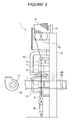
Figure 3 is a diagram generally showing the automatic winder. -
Figure 4 is a flowchart showing a first embodiment of a control method according to the present invention. -
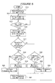
Figure 5 is a flowchart showing a second embodiment of a control method according to the present invention. - A first embodiment for an automatic winder to which a method for controlling a blower motor according to the present invention will be described with reference to
Figures 1 to 4 . As shown inFigure 2 , the automatic winder is composed of a group of windingunits 1 arranged in a row, a blower system 2 that supplies a negative pressure to each of the windingunits 1, and acontrol device 3 that manages the operation of the group of windingunits 1 and the blower system. - In
Figure 3 , the windingunit 1 is composed of amain body frame 5 fixed upright and shaped like a vertically long box, and serving as a base. Aballoon breaker 6, atension device 7, ayarn splicing device 8, aslab catcher 9, and the like are arranged on one side of themain body frame 5 in this order from the bottom to top of the frame. Atraverse drum 10, a cradle 11, and the like are arranged at the top of the above-described side of themain body frame 5; thetraverse drum 10 displaceably manipulates a yarn Y over a given width range, and the cradle 11 rotatably supports a package P. In addition to these devices, arelay pipe 12 andsuction mouth 13 are provided in a middle portion of the row of the above-described devices so as to be swingable in a vertical direction; therelay pipe 12 that sucks, catches, and passes the cut yarn Y to theyarn splicing device 8. - A spinning bobbin B is supported in an upright posture below the
balloon breaker 6. The yarn Y unwound from the spinning bobbin B is checked for a yarn defect while passing through the above-describeddevices 6 to 9. When a yarn defect is detected, the yarn is cut by a cutter provided in theslab catcher 9. The cutter constitutes a yarn cutting device according to the present invention. - During an operation of winding the yarn Y, a defective portion of the yarn Y is detected, and the yarn Y is cut. A yarn splicing operation is performed to remove the defective potion and splice an upper yarn and a lower yarn. When the yarn Y is cut, the upper yarn containing the defective portion is wound into the package P. The lower yarn is caught by the
relay pipe 12. Then, thesuction mouth 13 swings upward and sucks and catches an upper yarn end of the upper yarn wound into the package P. Subsequently, each of therelay pipe 12 and thesuction mouth 13 respectively swings to deliver the lower yarn and the upper yarn to theyarn splicing device 8, which removes the defective portion and splices the lower yarn and the upper yarn. The upper yarn, containing the defective portion, is sucked and caught by thesuction mouth 13, and when the upper yarn is spliced with the lower yarn by theyarn splicing device 8, the yarn end portion of the upper yarn, containing the defective portion, is cut by the cutter, provided in theyarn splicing device 8, and is disposed of as a waste yarn. A negative pressure supplied to the windingunit 1 is required for theyarn splicing device 8, therelay pipe 12, and thesuction mouth 13 mostly during the yarn splicing operation. The largest amount of negative pressure is consumed when thesuction mouth 13 sucks and catches the upper yarn end. - As shown in
Figures 2 and3 , the blower system 2 comprises anintake duct 16 including ablower 17 installed at one end and sealed at the other end, a motor (blower motor) 18 that rotationally drives theblower 17, aninverter 19 that supplies power to themotor 18, a manifold 20 that connects each of the windingunits 1 and theintake duct 16 together to supply a negative pressure, and asuction box 21 installed between theblower 17 and the windingunit 1. Theintake duct 16 is located to extend toward a rear surface side of the windingunit 1 along the direction of the row of the windingunits 1. Theblower 17 is a centrifugal fan in which an impeller rotates in a casing to generate the negative pressure. A filter (not shown in the drawings) is attached to thesuction box 21 to remove dust such as yarn waste which is sucked during the yarn splicing operation or the like. - The
control device 3 manages the operation of each windingunit 1 and the operation of the blower system 2. As shown inFigure 1 , thecontrol device 3 comprises acontrol section 23 that controls the devices and a memory 24 (storage section) in which various data is saved. Thememory 24 is a nonvolatile storage device from which no data is deleted even when a power supply is turned off. An input device (not shown in the drawings) is provided on a front surface of thecontrol device 3 so as to allow an operator to give an instruction on an operation or to change settings. - The negative pressure is supplied to each of the winding
units 1 by the blower system 2. When theinverter 19 supplies power to themotor 18, rotationally driving theblower 17, theblower 17 generates the negative pressure, and the negative pressure is supplied to the windingunit 1 via theintake duct 16 and the manifold 20. The supplied negative pressure enables each of the windingunits 1 to perform the yarn splicing operation or the like. The yarn Y is wound from the spinning bobbin B to form the package P. - The winding
unit 1 is supplied with the negative pressure by the blower system 2, and almost all of the negative pressure is used for the yarn splicing operation. In particular, the negative pressure is required for thesuction mouth 13, which sucks and catches the upper yarn wound into the package when the yarn Y is cut. When an insufficient negative pressure is supplied, thesuction mouth 13 fails to suck and catch the upper yarn end during the yarn splicing operation. The upper yarn end thus fails to be delivered to the yarn splicing device, preventing the yarn splicing operation from being completed. Where the yarn splicing operation fails to be completed, thesuction mouth 13 swings again to perform an operation of attempting to catch the upper yarn end. - As described above, the winding
unit 1 records the result of the yarn splicing operation. Thecontrol section 23 counts the upper yarn end leading mistake rate (MUP) of each of the winding units 1 (mistake rate calculating step) to calculate the upper yarn end leading mistake rate. Thecontrol section 23 compares the calculated mistake rate with the last calculated value stored in thememory 24 to increase or reduce the output frequency of theinverter 19. In the present embodiment, the output frequency of theinverter 19 is increased or reduced in increments of 1 Hz. - Where the calculated upper yarn end leading mistake rate (MUP) is higher than the last value, the output frequency of the
inverter 19 is controllably increased by 1 Hz to increase the rotation speed of themotor 18 and thus the negative pressure generated by theblower 17 in order to allow the yarn splicing operation to be smoothly operated. In contrast, where the calculated upper yarn end leading mistake rate (MUP) is lower than or the same as the last value, the output frequency of theinverter 19 is controllably reduced by 1 Hz to reduce the rotation speed of themotor 18 and thus the power supplied to themotor 18. The negative pressure generated by theblower 17 is thus reduced. - The method for controlling the blower motor and the frequency changing step according to the present embodiment will be described in further detail with reference to
Figure 4 . When the automatic winder is powered on, thecontrol section 23 reads the output frequency of theinverter 19 and the upper yarn end leading mistake rate (MUP) saved in the memory 24 (S1). That is, when the power supply is turned on, themotor 18 for theblower 17 is supplied with power at the last output frequency of theinverter 19. When a yarn winding operation is started, a timer is actuated to start clocking (S2). Once a set time for the winding operation elapses (YES in S3), thecontrol section 23 reads data recorded in theoperating winding unit 1. Thecontrol section 23 then calculates an MUP value on the basis of the data acquired and compares the MUP value with the last one saved in the memory 24 (S4). Where the compared MUP value is greater than the last value (YES in S5), the control section checks whether or not the current output frequency of theinverter 19 is equal to the maximum value preset in the control section 23 (S6). Where the output frequency is equal to the maximum value, thecontrol section 23 maintains the current output frequency (S7), and where the output frequency is not equal to the maximum value, thecontrol section 23 controls theinverter 19 such that the output frequency is increased by 1 Hz (S8). The increase in the output frequency of theinverter 19 increases the rotation speed of themotor 18 and thus the negative pressure supplied to the windingunit 1 increases by theblower 17. Thecontrol section 23 then saves the changed output frequency and the calculated MUP value to the memory 24 (S9), and allows the timer to start clocking again. - Then, where the compared MUP value is smaller than or the same as the last value (NO in S5), the
control section 23 checks whether or not the current output frequency of theinverter 19 is equal to the minimum value preset in the control section 23 (S10). Where the output frequency is equal to the minimum value, thecontrol section 23 maintains the current output frequency (S11), and where the output frequency is not equal to the maximum value, thecontrol section 23 controls theinverter 19 such that the output frequency is reduced by 1 Hz (S12). The decrease in the output frequency of theinverter 19 reduces the rotation speed of themotor 18 and thus the negative pressure supplied to the windingunit 1 by theblower 17 is reduced. Thecontrol section 23 then saves the changed output frequency and the calculated MUP value to the memory 24 (S9), and allows the timer to start clocking again. The saved output frequency is used as an initial value for the next starting of the blower system, and the MUP value is used as the last value for the next comparison. - A description will be given of a second embodiment of an automatic winder to which the method for controlling the blower motor according to the present invention is applied. The configuration of the automatic winder is the same as that of the first embodiment, and the description of the configuration is thus omitted. In the second embodiment, a preset threshold is compared with the calculated MUP value to control the output frequency of the
inverter 19 on the basis of the comparison result. - The method for controlling the blower motor according to the second embodiment of the present invention will be described with reference to
Figure 5 . When the automatic winder is powered on, thecontrol section 23 reads the output frequency of theinverter 19 saved in a memory 25 (S13). That is, when the power supply is turned on, themotor 18 for theblower 17 is supplied with power at the last output frequency of theinverter 19. When the yarn winding operation is started, the timer is actuated to start clocking (S14). Once the set time for the winding operation elapses (YES in S15), thecontrol section 23 reads data recorded in theoperating winding unit 1. Thecontrol section 23 then calculates the MUP value on the basis of the data acquired and compares the MUP value with the preset threshold value saved in the memory 24 (S16). Where the compared MUP value is greater than the last value (YES in S17), thecontrol section 23 checks whether or not the current output frequency of theinverter 19 is equal to the maximum value preset in the control section 23 (S18). Where the output frequency is equal to the maximum value, thecontrol section 23 maintains the current output frequency (S19). Where the output frequency is not equal to the maximum value, thecontrol section 23 controls theinverter 19 such that the output frequency is increased by 1 Hz (S20). The increase in the output frequency of theinverter 19 increases the rotation speed of themotor 18 and thus the negative pressure supplied to the windingunit 1 is increased by theblower 17. Thecontrol section 23 then saves the changed output frequency to the memory 24 (S21), and allows the timer to start clocking again. - Then, where the compared MUP value is smaller than or the same as the last value (NO in S17), the
control section 23 checks whether or not the current output frequency of theinverter 19 is equal to the minimum value preset in the control section 23 (S22). Where the output frequency is equal to the minimum value, thecontrol section 23 maintains the current output frequency (S23), and where the output frequency is not equal to the minimum value, thecontrol section 23 controls theinverter 19 such that the output frequency is reduced by 1 Hz (S24). The decrease in the output frequency of theinverter 19 reduces the rotation speed of themotor 18 and thus the negative pressure supplied to the windingunit 1 is reduced by theblower 17. Thecontrol section 23 then saves the changed output frequency to the memory 24 (S21), and allows the timer to start clocking again. The output frequency saved in S21 is used as an initial value for the next starting of the blower system. - As described above, the output frequency of the
inverter 19 is controlled on the basis of the upper yarn end leading mistake rate so as to control the rotation speed of themotor 18. Then, since the upper yarn end leading mistake rate is conventionally calculated utilizing the data managed by the windingunit 1 itself, thecontrol section 23 can determine whether or not the windingunit 1 is supplied with the appropriate negative pressure without the need for an additional device such as a pressure sensor. Therefore, the present invention eliminates the need for a sensor and enables a reduction in the costs of the automatic winder and facilitation of maintenance of the automatic winder. - The
control section 23 calculates the upper yarn end leading mistake rate of the windingunit 1 every set time, and thecontrol section 23 then compares the calculated rate with the last calculated upper yarn end leading mistake rate or the preset threshold value, which serves as a reference. Where the calculated upper yarn end leading mistake rate is greater than the last calculated value or the threshold value, thecontrol section 23 can determine that an insufficient negative pressure is being supplied to prevent thesuction mouth 13 from performing a proper upper yarn end leading operation. In this case, thecontrol section 23 controllably increases the output frequency of theinverter 19 and thus the rotation speed of themotor 18 so as to increase the negative pressure generated by theblower 17. Where the calculated upper yarn end leading mistake rate is smaller than the last calculated value or the threshold value, thecontrol section 23 can determine that a sufficient negative pressure is being supplied to allow thesuction mouth 13 to perform the proper upper yarn end leading operation. In this case, thecontrol section 23 controllably reduces the output frequency of theinverter 19 and thus the rotation speed of themotor 18 so as to reduce the negative pressure generated by theblower 17. In this manner, the output frequency of theinverter 19 is controlled so as to increase or reduce the negative pressure as required according to the operating status of the windingunit 1. Thus, the power consumed by themotor 18 can be reduced. This contributes to saving energy consumed by the automatic winder. - In addition, when the maximum and minimum values are set for the output frequency of the
inverter 19, the minimum value of the negative pressure to be supplied can be specified. Furthermore, the rotation speed of themotor 18 can be prevented from increasing beyond the appropriate range of the output characteristics of theblower 17. Additionally, the rotation speed of theblower 17 is prevented from decreasing or increasing abnormally. The reliability of the blower system 2 obtained can thus be improved. - While the present invention has been described with respect to preferred embodiments thereof, it will be apparent to those skilled in the art that the disclosed invention may be modified in numerous ways and may assume many embodiments other than those specifically set out and described above. Accordingly, it is intented by the appended claims to cover all modifications of the present invention that fall within the true spirit and scope of the invention.
Claims (9)
- A method for controlling a blower motor (18) for a blower system (2) that supplies a negative pressure used for a yarn splicing operation, to a plurality of winding units having a yarn splicing function, the method being characterized in that:number of yarn splicing operations in each of the winding units (1) and number of failures in yarn splicing are counted to calculate mistake rate (MUP) of the whole system, and an output frequency of an inverter (19) supplying power to the blower motor (18) is controllably increased or reduced on the basis of the mistake rate (MUP).
- A method for controlling a blower motor (18) according to Claim 1, characterized in that the blower system (2) includes an intake duct (16) comprising a plurality of manifolds (20) connected to the respective winding units (1), a blower (17) connected to one end of the intake duct (16) to generate a negative pressure, the blower motor (18) rotationally driving the blower (17), and an inverter (19) supplying power to the blower motor (18), and a rotation speed of said blower motor (18) is controlled by the output frequency of the inverter (19) supplying power to the blower motor (18), and in that the winding unit (1) comprises a yarn cutting device cutting a yarn when a yarn defect is detected, a yarn splicing device (8) performing an operation of splicing a lower yarn end and an upper yarn end formed by the yarn cutting operation, and a suction mouth (13) utilizing a negative pressure generated by the blower (17) to suck, catch, and deliver the upper yarn end to the yarn splicing device (8), and the method comprises a mistake rate calculating step of acquiring the number of yarn splicing operations in each of the winding units (1) and the number of failures in yarn splicing to calculate an upper yarn end leading mistake rate (MUP) of the whole system on the basis of the number of operations and the number of failures, and a frequency changing step of controllably increasing or reducing the output frequency of the inverter (19) on the basis of the upper yarn end leading mistake rate (MUP) calculated in the mistake rate calculating step.
- A method for controlling the blower motor (18) according to Claim 2, characterized in that in the mistake rate calculating step, the upper yarn end leading mistake rate (MUP) is calculated every set time and stored in a storage section (24), and in the frequency changing step, the last upper yarn end leading mistake rate stored in the storage section (24) is read, and where the calculated upper yarn end leading mistake rate (MUP) is higher than the read upper yarn end leading mistake rate, the output frequency of the inverter (19) is increased, and where the calculated upper yarn end leading mistake rate (MUP) is the same as or lower than the read upper yarn end leading mistake rate, the output frequency of said inverter (19) is reduced.
- A method for controlling the blower motor (18) according to Claim 2, characterized in that in the mistake rate calculating step, the upper yarn end leading mistake rate (MUP) is calculated every set time, and in the frequency changing step, the calculated upper yarn end leading mistake rate (MUP) is compared with a preset threshold value, and where the calculated upper yarn end leading mistake rate (MUP) is higher than the threshold value, the output frequency of the inverter (19) is increased, and where the calculated upper yarn end leading mistake rate is the same as or lower than the threshold value, the output frequency of said inverter (19) is reduced.
- A method for controlling the blower motor (18) according to any one of Claims 2 to 4, characterized in that in the frequency changing step, the output frequency of the inverter (19) is varied within a range between a preset maximum value and a preset minimum value.
- A blower system (2) supplying a negative pressure to a plurality of winding units (1) forming an automatic winder, the system being characterized by comprising an intake duct (16) including a plurality of manifolds (20) connected to the respective winding units (1), a blower (17) connected to one end of the intake duct (16) to generate a negative pressure, a blower motor (18) rotationally driving the blower (17), an inverter (19) supplying power to the blower motor (18), and a control section (23) controlling a rotation speed of the blower motor (18) by controllably increasing or reducing an output frequency of the inverter (19), and in that the winding unit (1) comprises a yarn cutting device cutting a yarn when a yarn defect is detected, a yarn splicing device (8) performing an operation of splicing a lower yarn end and an upper yarn end formed by the yarn cutting operation, and a suction mouth (13) utilizing a negative pressure generated by the blower (17) to suck, catch, and deliver the upper yarn end to the yarn splicing device (8) and in that the control section (23) acquires number of yarn splicing operations in each of the winding units (1) and number of failures in yarn splicing to calculate an upper yarn end leading mistake rate (MUP) of the whole system on the basis of the number of operations and the number of failures, and controllably increases or reduces the output frequency of the inverter (19) on the basis of the upper yarn end leading mistake rate (MUP).
- A blower system (2) according to Claim 6, characterized by further comprising a storage section (24) storing the upper yarn end leading mistake rate (MUP) calculated every set time by the control section (23), and in that when the upper yarn end leading mistake rate (MUP) is calculated, the control section (23) reads the last upper yarn end leading mistake rate stored in the storage section (24), and the control section (23) increases the output frequency of said inverter (19) where the calculated upper yarn end leading mistake rate (MUP) is higher than the read upper yarn end leading mistake rate, and reduces the output frequency of the inverter (19) where the calculated upper yarn end leading mistake rate (MUP) is the same as or lower than the read upper yarn end leading mistake rate.
- A blower system (2) according to Claim 6, characterized by further comprising a storage section (24) storing a preset threshold value, and when the upper yarn end leading mistake rate is calculated, the control section (23) compares the calculated upper yarn end leading mistake with a threshold value stored in the storage section (24), and the control section (23) increases the output frequency of said inverter (19) where the calculated upper yarn end leading mistake rate (MUP) is higher than the threshold value, and reduces the output frequency of the inverter (19) where the calculated upper yarn end leading mistake rate (MUP) is the same as or lower than the threshold value.
- A blower system (2) according to any one of Claims 6 to 8, characterized in that the control section (23) varies the output frequency of the inverter (19) within a range between a preset maximum value and a preset minimum value.
Applications Claiming Priority (1)
| Application Number | Priority Date | Filing Date | Title |
|---|---|---|---|
| JP2007276186A JP2009102132A (en) | 2007-10-24 | 2007-10-24 | Control method for blower motor and blower system |
Publications (1)
| Publication Number | Publication Date |
|---|---|
| EP2053006A2 true EP2053006A2 (en) | 2009-04-29 |
Family
ID=40282358
Family Applications (1)
| Application Number | Title | Priority Date | Filing Date |
|---|---|---|---|
| EP08016249A Withdrawn EP2053006A2 (en) | 2007-10-24 | 2008-09-15 | Method for controlling blower motor and blower system |
Country Status (3)
| Country | Link |
|---|---|
| EP (1) | EP2053006A2 (en) |
| JP (1) | JP2009102132A (en) |
| CN (1) | CN101419473A (en) |
Cited By (2)
| Publication number | Priority date | Publication date | Assignee | Title |
|---|---|---|---|---|
| ITMI20092013A1 (en) * | 2009-11-16 | 2011-05-17 | Savio Macchine Tessili Spa | INDIVIDUAL ASPIRATION SYSTEM FOR ROCKING UNIT |
| EP3511274A1 (en) * | 2018-01-16 | 2019-07-17 | Murata Machinery, Ltd. | Static pressure control method in automatic winder and automatic winder |
Families Citing this family (4)
| Publication number | Priority date | Publication date | Assignee | Title |
|---|---|---|---|---|
| DE102015013569A1 (en) * | 2015-10-20 | 2017-04-20 | Saurer Germany Gmbh & Co. Kg | A method of calibrating an upper thread detection process of work stations of a cross-wound textile machine |
| CN108343627A (en) * | 2018-02-11 | 2018-07-31 | 上海联达节能科技股份有限公司 | A kind of remodeling method of dedusting fan frequency-changing control system and dust pelletizing system |
| JP2020142897A (en) * | 2019-03-06 | 2020-09-10 | 村田機械株式会社 | Compressed air consumption output device and textile machine |
| CN115463530B (en) * | 2022-07-29 | 2023-10-13 | 北京京仪自动化装备技术股份有限公司 | Negative pressure control method, semiconductor exhaust gas treatment apparatus, and storage medium |
Citations (1)
| Publication number | Priority date | Publication date | Assignee | Title |
|---|---|---|---|---|
| JPH0240759U (en) | 1988-09-13 | 1990-03-20 |
Family Cites Families (3)
| Publication number | Priority date | Publication date | Assignee | Title |
|---|---|---|---|---|
| JPS6133470A (en) * | 1984-07-26 | 1986-02-17 | Murata Mach Ltd | Central blower in winder |
| JPH0240759A (en) * | 1988-07-29 | 1990-02-09 | Nec Corp | External data incorporation system |
| DE19653617A1 (en) * | 1996-12-20 | 1998-06-25 | Schlafhorst & Co W | Process for regulating the negative pressure in a suction air system of a textile machine |
-
2007
- 2007-10-24 JP JP2007276186A patent/JP2009102132A/en active Pending
-
2008
- 2008-08-29 CN CNA2008101468009A patent/CN101419473A/en active Pending
- 2008-09-15 EP EP08016249A patent/EP2053006A2/en not_active Withdrawn
Patent Citations (1)
| Publication number | Priority date | Publication date | Assignee | Title |
|---|---|---|---|---|
| JPH0240759U (en) | 1988-09-13 | 1990-03-20 |
Cited By (5)
| Publication number | Priority date | Publication date | Assignee | Title |
|---|---|---|---|---|
| ITMI20092013A1 (en) * | 2009-11-16 | 2011-05-17 | Savio Macchine Tessili Spa | INDIVIDUAL ASPIRATION SYSTEM FOR ROCKING UNIT |
| EP2322458A1 (en) * | 2009-11-16 | 2011-05-18 | Savio Macchine Tessili S.p.A. | Individual suction system for a winding unit |
| EP3511274A1 (en) * | 2018-01-16 | 2019-07-17 | Murata Machinery, Ltd. | Static pressure control method in automatic winder and automatic winder |
| CN110040572A (en) * | 2018-01-16 | 2019-07-23 | 村田机械株式会社 | The static pressure control method and automatic bobbin winder of automatic bobbin winder |
| CN110040572B (en) * | 2018-01-16 | 2022-04-05 | 村田机械株式会社 | Static pressure control method of automatic winder and automatic winder |
Also Published As
| Publication number | Publication date |
|---|---|
| JP2009102132A (en) | 2009-05-14 |
| CN101419473A (en) | 2009-04-29 |
Similar Documents
| Publication | Publication Date | Title |
|---|---|---|
| EP2377793B1 (en) | Yarn winding device and automatic winder | |
| JP5190703B2 (en) | Yarn winding device and automatic winder | |
| JP6351300B2 (en) | A method for optimizing negative pressure in a suction device of a textile machine producing a trample package | |
| JP2009102132A (en) | Control method for blower motor and blower system | |
| EP2105398A2 (en) | Yarn Winding Apparatus | |
| EP1882663B1 (en) | Device for pulling out a yarn end from a winding package | |
| CN106672698B (en) | Method for operating the weaving loom of production cross winding bobbin | |
| JP2011006179A (en) | Yarn winding device | |
| EP2511215B1 (en) | Automatic winder | |
| JP2000238963A (en) | Method of operating one working unit of a textile machine for winding a twill package | |
| JPH10194590A (en) | Method for controlling negative pressure in air suction device for fiber machine | |
| JP2012076884A (en) | Circuit board for yarn winding device, and yarn winding device | |
| JP4277227B2 (en) | Method for extracting winding package in automatic winder and automatic winder | |
| JP2015009965A (en) | Automatic winder | |
| EP2700601A2 (en) | Yarn winding unit and yarn winding machine | |
| JPH06322622A (en) | Automatic winder | |
| EP3511274B1 (en) | Static pressure control method in automatic winder and automatic winder | |
| JP3006562B2 (en) | Power outage processing system for yarn winding machine | |
| JP3726715B2 (en) | Automatic winder tension control device | |
| JP2023142771A (en) | Yarn winding machine and yarn winding method | |
| CN111032548B (en) | Automatic winder, yarn winding module, piecing module, yarn supply and replacement module included in the automatic winder, and method for manufacturing the automatic winder | |
| CN215557930U (en) | Wire end winding device of wire rewinding machine | |
| JP2019034847A (en) | Automatic winder, and manufacturing method of automatic winder | |
| JP3430631B2 (en) | Automatic winder | |
| KR20260029637A (en) | Automatic sewing thread winder of thread cuting and discharge apparatus |
Legal Events
| Date | Code | Title | Description |
|---|---|---|---|
| PUAI | Public reference made under article 153(3) epc to a published international application that has entered the european phase |
Free format text: ORIGINAL CODE: 0009012 |
|
| AK | Designated contracting states |
Kind code of ref document: A2 Designated state(s): AT BE BG CH CY CZ DE DK EE ES FI FR GB GR HR HU IE IS IT LI LT LU LV MC MT NL NO PL PT RO SE SI SK TR |
|
| AX | Request for extension of the european patent |
Extension state: AL BA MK RS |
|
| STAA | Information on the status of an ep patent application or granted ep patent |
Free format text: STATUS: THE APPLICATION IS DEEMED TO BE WITHDRAWN |
|
| 18D | Application deemed to be withdrawn |
Effective date: 20110331 |