EP2052933A2 - Verfahren und Vorrichtung zur Kontrolle eines abweichenden Kupplungsdrehmoments während der Drehmomentphase für eine Hybridübertragungssystem - Google Patents
Verfahren und Vorrichtung zur Kontrolle eines abweichenden Kupplungsdrehmoments während der Drehmomentphase für eine Hybridübertragungssystem Download PDFInfo
- Publication number
- EP2052933A2 EP2052933A2 EP08018704A EP08018704A EP2052933A2 EP 2052933 A2 EP2052933 A2 EP 2052933A2 EP 08018704 A EP08018704 A EP 08018704A EP 08018704 A EP08018704 A EP 08018704A EP 2052933 A2 EP2052933 A2 EP 2052933A2
- Authority
- EP
- European Patent Office
- Prior art keywords
- torque
- clutch
- electric machine
- reactive
- decreasing
- Prior art date
- Legal status (The legal status is an assumption and is not a legal conclusion. Google has not performed a legal analysis and makes no representation as to the accuracy of the status listed.)
- Granted
Links
Images


Classifications
-
- B—PERFORMING OPERATIONS; TRANSPORTING
- B60—VEHICLES IN GENERAL
- B60W—CONJOINT CONTROL OF VEHICLE SUB-UNITS OF DIFFERENT TYPE OR DIFFERENT FUNCTION; CONTROL SYSTEMS SPECIALLY ADAPTED FOR HYBRID VEHICLES; ROAD VEHICLE DRIVE CONTROL SYSTEMS FOR PURPOSES NOT RELATED TO THE CONTROL OF A PARTICULAR SUB-UNIT
- B60W20/00—Control systems specially adapted for hybrid vehicles
- B60W20/40—Controlling the engagement or disengagement of prime movers, e.g. for transition between prime movers
-
- B—PERFORMING OPERATIONS; TRANSPORTING
- B60—VEHICLES IN GENERAL
- B60K—ARRANGEMENT OR MOUNTING OF PROPULSION UNITS OR OF TRANSMISSIONS IN VEHICLES; ARRANGEMENT OR MOUNTING OF PLURAL DIVERSE PRIME-MOVERS IN VEHICLES; AUXILIARY DRIVES FOR VEHICLES; INSTRUMENTATION OR DASHBOARDS FOR VEHICLES; ARRANGEMENTS IN CONNECTION WITH COOLING, AIR INTAKE, GAS EXHAUST OR FUEL SUPPLY OF PROPULSION UNITS IN VEHICLES
- B60K6/00—Arrangement or mounting of plural diverse prime-movers for mutual or common propulsion, e.g. hybrid propulsion systems comprising electric motors and internal combustion engines
- B60K6/20—Arrangement or mounting of plural diverse prime-movers for mutual or common propulsion, e.g. hybrid propulsion systems comprising electric motors and internal combustion engines the prime-movers consisting of electric motors and internal combustion engines, e.g. HEVs
- B60K6/42—Arrangement or mounting of plural diverse prime-movers for mutual or common propulsion, e.g. hybrid propulsion systems comprising electric motors and internal combustion engines the prime-movers consisting of electric motors and internal combustion engines, e.g. HEVs characterised by the architecture of the hybrid electric vehicle
- B60K6/44—Series-parallel type
- B60K6/445—Differential gearing distribution type
-
- B—PERFORMING OPERATIONS; TRANSPORTING
- B60—VEHICLES IN GENERAL
- B60K—ARRANGEMENT OR MOUNTING OF PROPULSION UNITS OR OF TRANSMISSIONS IN VEHICLES; ARRANGEMENT OR MOUNTING OF PLURAL DIVERSE PRIME-MOVERS IN VEHICLES; AUXILIARY DRIVES FOR VEHICLES; INSTRUMENTATION OR DASHBOARDS FOR VEHICLES; ARRANGEMENTS IN CONNECTION WITH COOLING, AIR INTAKE, GAS EXHAUST OR FUEL SUPPLY OF PROPULSION UNITS IN VEHICLES
- B60K6/00—Arrangement or mounting of plural diverse prime-movers for mutual or common propulsion, e.g. hybrid propulsion systems comprising electric motors and internal combustion engines
- B60K6/20—Arrangement or mounting of plural diverse prime-movers for mutual or common propulsion, e.g. hybrid propulsion systems comprising electric motors and internal combustion engines the prime-movers consisting of electric motors and internal combustion engines, e.g. HEVs
- B60K6/50—Architecture of the driveline characterised by arrangement or kind of transmission units
- B60K6/54—Transmission for changing ratio
- B60K6/547—Transmission for changing ratio the transmission being a stepped gearing
-
- B—PERFORMING OPERATIONS; TRANSPORTING
- B60—VEHICLES IN GENERAL
- B60W—CONJOINT CONTROL OF VEHICLE SUB-UNITS OF DIFFERENT TYPE OR DIFFERENT FUNCTION; CONTROL SYSTEMS SPECIALLY ADAPTED FOR HYBRID VEHICLES; ROAD VEHICLE DRIVE CONTROL SYSTEMS FOR PURPOSES NOT RELATED TO THE CONTROL OF A PARTICULAR SUB-UNIT
- B60W10/00—Conjoint control of vehicle sub-units of different type or different function
- B60W10/02—Conjoint control of vehicle sub-units of different type or different function including control of driveline clutches
-
- B—PERFORMING OPERATIONS; TRANSPORTING
- B60—VEHICLES IN GENERAL
- B60W—CONJOINT CONTROL OF VEHICLE SUB-UNITS OF DIFFERENT TYPE OR DIFFERENT FUNCTION; CONTROL SYSTEMS SPECIALLY ADAPTED FOR HYBRID VEHICLES; ROAD VEHICLE DRIVE CONTROL SYSTEMS FOR PURPOSES NOT RELATED TO THE CONTROL OF A PARTICULAR SUB-UNIT
- B60W10/00—Conjoint control of vehicle sub-units of different type or different function
- B60W10/04—Conjoint control of vehicle sub-units of different type or different function including control of propulsion units
- B60W10/06—Conjoint control of vehicle sub-units of different type or different function including control of propulsion units including control of combustion engines
-
- B—PERFORMING OPERATIONS; TRANSPORTING
- B60—VEHICLES IN GENERAL
- B60W—CONJOINT CONTROL OF VEHICLE SUB-UNITS OF DIFFERENT TYPE OR DIFFERENT FUNCTION; CONTROL SYSTEMS SPECIALLY ADAPTED FOR HYBRID VEHICLES; ROAD VEHICLE DRIVE CONTROL SYSTEMS FOR PURPOSES NOT RELATED TO THE CONTROL OF A PARTICULAR SUB-UNIT
- B60W10/00—Conjoint control of vehicle sub-units of different type or different function
- B60W10/04—Conjoint control of vehicle sub-units of different type or different function including control of propulsion units
- B60W10/08—Conjoint control of vehicle sub-units of different type or different function including control of propulsion units including control of electric propulsion units, e.g. motors or generators
-
- B—PERFORMING OPERATIONS; TRANSPORTING
- B60—VEHICLES IN GENERAL
- B60W—CONJOINT CONTROL OF VEHICLE SUB-UNITS OF DIFFERENT TYPE OR DIFFERENT FUNCTION; CONTROL SYSTEMS SPECIALLY ADAPTED FOR HYBRID VEHICLES; ROAD VEHICLE DRIVE CONTROL SYSTEMS FOR PURPOSES NOT RELATED TO THE CONTROL OF A PARTICULAR SUB-UNIT
- B60W20/00—Control systems specially adapted for hybrid vehicles
-
- B—PERFORMING OPERATIONS; TRANSPORTING
- B60—VEHICLES IN GENERAL
- B60K—ARRANGEMENT OR MOUNTING OF PROPULSION UNITS OR OF TRANSMISSIONS IN VEHICLES; ARRANGEMENT OR MOUNTING OF PLURAL DIVERSE PRIME-MOVERS IN VEHICLES; AUXILIARY DRIVES FOR VEHICLES; INSTRUMENTATION OR DASHBOARDS FOR VEHICLES; ARRANGEMENTS IN CONNECTION WITH COOLING, AIR INTAKE, GAS EXHAUST OR FUEL SUPPLY OF PROPULSION UNITS IN VEHICLES
- B60K1/00—Arrangement or mounting of electrical propulsion units
- B60K1/02—Arrangement or mounting of electrical propulsion units comprising more than one electric motor
-
- B—PERFORMING OPERATIONS; TRANSPORTING
- B60—VEHICLES IN GENERAL
- B60K—ARRANGEMENT OR MOUNTING OF PROPULSION UNITS OR OF TRANSMISSIONS IN VEHICLES; ARRANGEMENT OR MOUNTING OF PLURAL DIVERSE PRIME-MOVERS IN VEHICLES; AUXILIARY DRIVES FOR VEHICLES; INSTRUMENTATION OR DASHBOARDS FOR VEHICLES; ARRANGEMENTS IN CONNECTION WITH COOLING, AIR INTAKE, GAS EXHAUST OR FUEL SUPPLY OF PROPULSION UNITS IN VEHICLES
- B60K6/00—Arrangement or mounting of plural diverse prime-movers for mutual or common propulsion, e.g. hybrid propulsion systems comprising electric motors and internal combustion engines
- B60K6/20—Arrangement or mounting of plural diverse prime-movers for mutual or common propulsion, e.g. hybrid propulsion systems comprising electric motors and internal combustion engines the prime-movers consisting of electric motors and internal combustion engines, e.g. HEVs
- B60K6/22—Arrangement or mounting of plural diverse prime-movers for mutual or common propulsion, e.g. hybrid propulsion systems comprising electric motors and internal combustion engines the prime-movers consisting of electric motors and internal combustion engines, e.g. HEVs characterised by apparatus, components or means specially adapted for HEVs
- B60K6/26—Arrangement or mounting of plural diverse prime-movers for mutual or common propulsion, e.g. hybrid propulsion systems comprising electric motors and internal combustion engines the prime-movers consisting of electric motors and internal combustion engines, e.g. HEVs characterised by apparatus, components or means specially adapted for HEVs characterised by the motors or the generators
-
- B—PERFORMING OPERATIONS; TRANSPORTING
- B60—VEHICLES IN GENERAL
- B60K—ARRANGEMENT OR MOUNTING OF PROPULSION UNITS OR OF TRANSMISSIONS IN VEHICLES; ARRANGEMENT OR MOUNTING OF PLURAL DIVERSE PRIME-MOVERS IN VEHICLES; AUXILIARY DRIVES FOR VEHICLES; INSTRUMENTATION OR DASHBOARDS FOR VEHICLES; ARRANGEMENTS IN CONNECTION WITH COOLING, AIR INTAKE, GAS EXHAUST OR FUEL SUPPLY OF PROPULSION UNITS IN VEHICLES
- B60K6/00—Arrangement or mounting of plural diverse prime-movers for mutual or common propulsion, e.g. hybrid propulsion systems comprising electric motors and internal combustion engines
- B60K6/20—Arrangement or mounting of plural diverse prime-movers for mutual or common propulsion, e.g. hybrid propulsion systems comprising electric motors and internal combustion engines the prime-movers consisting of electric motors and internal combustion engines, e.g. HEVs
- B60K6/22—Arrangement or mounting of plural diverse prime-movers for mutual or common propulsion, e.g. hybrid propulsion systems comprising electric motors and internal combustion engines the prime-movers consisting of electric motors and internal combustion engines, e.g. HEVs characterised by apparatus, components or means specially adapted for HEVs
- B60K6/36—Arrangement or mounting of plural diverse prime-movers for mutual or common propulsion, e.g. hybrid propulsion systems comprising electric motors and internal combustion engines the prime-movers consisting of electric motors and internal combustion engines, e.g. HEVs characterised by apparatus, components or means specially adapted for HEVs characterised by the transmission gearings
- B60K6/365—Arrangement or mounting of plural diverse prime-movers for mutual or common propulsion, e.g. hybrid propulsion systems comprising electric motors and internal combustion engines the prime-movers consisting of electric motors and internal combustion engines, e.g. HEVs characterised by apparatus, components or means specially adapted for HEVs characterised by the transmission gearings with the gears having orbital motion
-
- B—PERFORMING OPERATIONS; TRANSPORTING
- B60—VEHICLES IN GENERAL
- B60L—PROPULSION OF ELECTRICALLY-PROPELLED VEHICLES; SUPPLYING ELECTRIC POWER FOR AUXILIARY EQUIPMENT OF ELECTRICALLY-PROPELLED VEHICLES; ELECTRODYNAMIC BRAKE SYSTEMS FOR VEHICLES IN GENERAL; MAGNETIC SUSPENSION OR LEVITATION FOR VEHICLES; MONITORING OPERATING VARIABLES OF ELECTRICALLY-PROPELLED VEHICLES; ELECTRIC SAFETY DEVICES FOR ELECTRICALLY-PROPELLED VEHICLES
- B60L2240/00—Control parameters of input or output; Target parameters
- B60L2240/40—Drive Train control parameters
- B60L2240/42—Drive Train control parameters related to electric machines
- B60L2240/421—Speed
-
- B—PERFORMING OPERATIONS; TRANSPORTING
- B60—VEHICLES IN GENERAL
- B60L—PROPULSION OF ELECTRICALLY-PROPELLED VEHICLES; SUPPLYING ELECTRIC POWER FOR AUXILIARY EQUIPMENT OF ELECTRICALLY-PROPELLED VEHICLES; ELECTRODYNAMIC BRAKE SYSTEMS FOR VEHICLES IN GENERAL; MAGNETIC SUSPENSION OR LEVITATION FOR VEHICLES; MONITORING OPERATING VARIABLES OF ELECTRICALLY-PROPELLED VEHICLES; ELECTRIC SAFETY DEVICES FOR ELECTRICALLY-PROPELLED VEHICLES
- B60L2240/00—Control parameters of input or output; Target parameters
- B60L2240/40—Drive Train control parameters
- B60L2240/44—Drive Train control parameters related to combustion engines
- B60L2240/441—Speed
-
- B—PERFORMING OPERATIONS; TRANSPORTING
- B60—VEHICLES IN GENERAL
- B60L—PROPULSION OF ELECTRICALLY-PROPELLED VEHICLES; SUPPLYING ELECTRIC POWER FOR AUXILIARY EQUIPMENT OF ELECTRICALLY-PROPELLED VEHICLES; ELECTRODYNAMIC BRAKE SYSTEMS FOR VEHICLES IN GENERAL; MAGNETIC SUSPENSION OR LEVITATION FOR VEHICLES; MONITORING OPERATING VARIABLES OF ELECTRICALLY-PROPELLED VEHICLES; ELECTRIC SAFETY DEVICES FOR ELECTRICALLY-PROPELLED VEHICLES
- B60L2240/00—Control parameters of input or output; Target parameters
- B60L2240/40—Drive Train control parameters
- B60L2240/48—Drive Train control parameters related to transmissions
- B60L2240/486—Operating parameters
-
- B—PERFORMING OPERATIONS; TRANSPORTING
- B60—VEHICLES IN GENERAL
- B60W—CONJOINT CONTROL OF VEHICLE SUB-UNITS OF DIFFERENT TYPE OR DIFFERENT FUNCTION; CONTROL SYSTEMS SPECIALLY ADAPTED FOR HYBRID VEHICLES; ROAD VEHICLE DRIVE CONTROL SYSTEMS FOR PURPOSES NOT RELATED TO THE CONTROL OF A PARTICULAR SUB-UNIT
- B60W50/00—Details of control systems for road vehicle drive control not related to the control of a particular sub-unit, e.g. process diagnostic or vehicle driver interfaces
- B60W2050/0001—Details of the control system
- B60W2050/0019—Control system elements or transfer functions
- B60W2050/0042—Transfer function lag; delays
-
- B—PERFORMING OPERATIONS; TRANSPORTING
- B60—VEHICLES IN GENERAL
- B60W—CONJOINT CONTROL OF VEHICLE SUB-UNITS OF DIFFERENT TYPE OR DIFFERENT FUNCTION; CONTROL SYSTEMS SPECIALLY ADAPTED FOR HYBRID VEHICLES; ROAD VEHICLE DRIVE CONTROL SYSTEMS FOR PURPOSES NOT RELATED TO THE CONTROL OF A PARTICULAR SUB-UNIT
- B60W2510/00—Input parameters relating to a particular sub-units
- B60W2510/02—Clutches
- B60W2510/0241—Clutch slip, i.e. difference between input and output speeds
-
- B—PERFORMING OPERATIONS; TRANSPORTING
- B60—VEHICLES IN GENERAL
- B60W—CONJOINT CONTROL OF VEHICLE SUB-UNITS OF DIFFERENT TYPE OR DIFFERENT FUNCTION; CONTROL SYSTEMS SPECIALLY ADAPTED FOR HYBRID VEHICLES; ROAD VEHICLE DRIVE CONTROL SYSTEMS FOR PURPOSES NOT RELATED TO THE CONTROL OF A PARTICULAR SUB-UNIT
- B60W2510/00—Input parameters relating to a particular sub-units
- B60W2510/06—Combustion engines, Gas turbines
- B60W2510/0638—Engine speed
-
- B—PERFORMING OPERATIONS; TRANSPORTING
- B60—VEHICLES IN GENERAL
- B60W—CONJOINT CONTROL OF VEHICLE SUB-UNITS OF DIFFERENT TYPE OR DIFFERENT FUNCTION; CONTROL SYSTEMS SPECIALLY ADAPTED FOR HYBRID VEHICLES; ROAD VEHICLE DRIVE CONTROL SYSTEMS FOR PURPOSES NOT RELATED TO THE CONTROL OF A PARTICULAR SUB-UNIT
- B60W2510/00—Input parameters relating to a particular sub-units
- B60W2510/08—Electric propulsion units
- B60W2510/081—Speed
-
- B—PERFORMING OPERATIONS; TRANSPORTING
- B60—VEHICLES IN GENERAL
- B60W—CONJOINT CONTROL OF VEHICLE SUB-UNITS OF DIFFERENT TYPE OR DIFFERENT FUNCTION; CONTROL SYSTEMS SPECIALLY ADAPTED FOR HYBRID VEHICLES; ROAD VEHICLE DRIVE CONTROL SYSTEMS FOR PURPOSES NOT RELATED TO THE CONTROL OF A PARTICULAR SUB-UNIT
- B60W2510/00—Input parameters relating to a particular sub-units
- B60W2510/10—Change speed gearings
- B60W2510/104—Output speed
-
- B—PERFORMING OPERATIONS; TRANSPORTING
- B60—VEHICLES IN GENERAL
- B60W—CONJOINT CONTROL OF VEHICLE SUB-UNITS OF DIFFERENT TYPE OR DIFFERENT FUNCTION; CONTROL SYSTEMS SPECIALLY ADAPTED FOR HYBRID VEHICLES; ROAD VEHICLE DRIVE CONTROL SYSTEMS FOR PURPOSES NOT RELATED TO THE CONTROL OF A PARTICULAR SUB-UNIT
- B60W2540/00—Input parameters relating to occupants
- B60W2540/10—Accelerator pedal position
-
- B—PERFORMING OPERATIONS; TRANSPORTING
- B60—VEHICLES IN GENERAL
- B60W—CONJOINT CONTROL OF VEHICLE SUB-UNITS OF DIFFERENT TYPE OR DIFFERENT FUNCTION; CONTROL SYSTEMS SPECIALLY ADAPTED FOR HYBRID VEHICLES; ROAD VEHICLE DRIVE CONTROL SYSTEMS FOR PURPOSES NOT RELATED TO THE CONTROL OF A PARTICULAR SUB-UNIT
- B60W2540/00—Input parameters relating to occupants
- B60W2540/12—Brake pedal position
-
- B—PERFORMING OPERATIONS; TRANSPORTING
- B60—VEHICLES IN GENERAL
- B60W—CONJOINT CONTROL OF VEHICLE SUB-UNITS OF DIFFERENT TYPE OR DIFFERENT FUNCTION; CONTROL SYSTEMS SPECIALLY ADAPTED FOR HYBRID VEHICLES; ROAD VEHICLE DRIVE CONTROL SYSTEMS FOR PURPOSES NOT RELATED TO THE CONTROL OF A PARTICULAR SUB-UNIT
- B60W2710/00—Output or target parameters relating to a particular sub-units
- B60W2710/02—Clutches
- B60W2710/025—Clutch slip, i.e. difference between input and output speeds
-
- F—MECHANICAL ENGINEERING; LIGHTING; HEATING; WEAPONS; BLASTING
- F16—ENGINEERING ELEMENTS AND UNITS; GENERAL MEASURES FOR PRODUCING AND MAINTAINING EFFECTIVE FUNCTIONING OF MACHINES OR INSTALLATIONS; THERMAL INSULATION IN GENERAL
- F16H—GEARING
- F16H37/00—Combinations of mechanical gearings, not provided for in groups F16H1/00 - F16H35/00
- F16H37/02—Combinations of mechanical gearings, not provided for in groups F16H1/00 - F16H35/00 comprising essentially only toothed or friction gearings
- F16H37/06—Combinations of mechanical gearings, not provided for in groups F16H1/00 - F16H35/00 comprising essentially only toothed or friction gearings with a plurality of driving or driven shafts; with arrangements for dividing torque between two or more intermediate shafts
- F16H37/08—Combinations of mechanical gearings, not provided for in groups F16H1/00 - F16H35/00 comprising essentially only toothed or friction gearings with a plurality of driving or driven shafts; with arrangements for dividing torque between two or more intermediate shafts with differential gearing
- F16H37/0833—Combinations of mechanical gearings, not provided for in groups F16H1/00 - F16H35/00 comprising essentially only toothed or friction gearings with a plurality of driving or driven shafts; with arrangements for dividing torque between two or more intermediate shafts with differential gearing with arrangements for dividing torque between two or more intermediate shafts, i.e. with two or more internal power paths
- F16H37/084—Combinations of mechanical gearings, not provided for in groups F16H1/00 - F16H35/00 comprising essentially only toothed or friction gearings with a plurality of driving or driven shafts; with arrangements for dividing torque between two or more intermediate shafts with differential gearing with arrangements for dividing torque between two or more intermediate shafts, i.e. with two or more internal power paths at least one power path being a continuously variable transmission, i.e. CVT
- F16H2037/0866—Power-split transmissions with distributing differentials, with the output of the CVT connected or connectable to the output shaft
-
- F—MECHANICAL ENGINEERING; LIGHTING; HEATING; WEAPONS; BLASTING
- F16—ENGINEERING ELEMENTS AND UNITS; GENERAL MEASURES FOR PRODUCING AND MAINTAINING EFFECTIVE FUNCTIONING OF MACHINES OR INSTALLATIONS; THERMAL INSULATION IN GENERAL
- F16H—GEARING
- F16H37/00—Combinations of mechanical gearings, not provided for in groups F16H1/00 - F16H35/00
- F16H37/02—Combinations of mechanical gearings, not provided for in groups F16H1/00 - F16H35/00 comprising essentially only toothed or friction gearings
- F16H37/06—Combinations of mechanical gearings, not provided for in groups F16H1/00 - F16H35/00 comprising essentially only toothed or friction gearings with a plurality of driving or driven shafts; with arrangements for dividing torque between two or more intermediate shafts
- F16H37/08—Combinations of mechanical gearings, not provided for in groups F16H1/00 - F16H35/00 comprising essentially only toothed or friction gearings with a plurality of driving or driven shafts; with arrangements for dividing torque between two or more intermediate shafts with differential gearing
- F16H37/10—Combinations of mechanical gearings, not provided for in groups F16H1/00 - F16H35/00 comprising essentially only toothed or friction gearings with a plurality of driving or driven shafts; with arrangements for dividing torque between two or more intermediate shafts with differential gearing at both ends of intermediate shafts
- F16H2037/102—Combinations of mechanical gearings, not provided for in groups F16H1/00 - F16H35/00 comprising essentially only toothed or friction gearings with a plurality of driving or driven shafts; with arrangements for dividing torque between two or more intermediate shafts with differential gearing at both ends of intermediate shafts the input or output shaft of the transmission is connected or connectable to two or more differentials
-
- F—MECHANICAL ENGINEERING; LIGHTING; HEATING; WEAPONS; BLASTING
- F16—ENGINEERING ELEMENTS AND UNITS; GENERAL MEASURES FOR PRODUCING AND MAINTAINING EFFECTIVE FUNCTIONING OF MACHINES OR INSTALLATIONS; THERMAL INSULATION IN GENERAL
- F16H—GEARING
- F16H37/00—Combinations of mechanical gearings, not provided for in groups F16H1/00 - F16H35/00
- F16H37/02—Combinations of mechanical gearings, not provided for in groups F16H1/00 - F16H35/00 comprising essentially only toothed or friction gearings
- F16H37/06—Combinations of mechanical gearings, not provided for in groups F16H1/00 - F16H35/00 comprising essentially only toothed or friction gearings with a plurality of driving or driven shafts; with arrangements for dividing torque between two or more intermediate shafts
- F16H37/08—Combinations of mechanical gearings, not provided for in groups F16H1/00 - F16H35/00 comprising essentially only toothed or friction gearings with a plurality of driving or driven shafts; with arrangements for dividing torque between two or more intermediate shafts with differential gearing
- F16H37/10—Combinations of mechanical gearings, not provided for in groups F16H1/00 - F16H35/00 comprising essentially only toothed or friction gearings with a plurality of driving or driven shafts; with arrangements for dividing torque between two or more intermediate shafts with differential gearing at both ends of intermediate shafts
- F16H2037/104—Power-split transmissions with at least one end of a CVT connected or connectable to two or more differentials
-
- F—MECHANICAL ENGINEERING; LIGHTING; HEATING; WEAPONS; BLASTING
- F16—ENGINEERING ELEMENTS AND UNITS; GENERAL MEASURES FOR PRODUCING AND MAINTAINING EFFECTIVE FUNCTIONING OF MACHINES OR INSTALLATIONS; THERMAL INSULATION IN GENERAL
- F16H—GEARING
- F16H37/00—Combinations of mechanical gearings, not provided for in groups F16H1/00 - F16H35/00
- F16H37/02—Combinations of mechanical gearings, not provided for in groups F16H1/00 - F16H35/00 comprising essentially only toothed or friction gearings
- F16H37/06—Combinations of mechanical gearings, not provided for in groups F16H1/00 - F16H35/00 comprising essentially only toothed or friction gearings with a plurality of driving or driven shafts; with arrangements for dividing torque between two or more intermediate shafts
- F16H37/08—Combinations of mechanical gearings, not provided for in groups F16H1/00 - F16H35/00 comprising essentially only toothed or friction gearings with a plurality of driving or driven shafts; with arrangements for dividing torque between two or more intermediate shafts with differential gearing
- F16H37/10—Combinations of mechanical gearings, not provided for in groups F16H1/00 - F16H35/00 comprising essentially only toothed or friction gearings with a plurality of driving or driven shafts; with arrangements for dividing torque between two or more intermediate shafts with differential gearing at both ends of intermediate shafts
- F16H2037/105—Combinations of mechanical gearings, not provided for in groups F16H1/00 - F16H35/00 comprising essentially only toothed or friction gearings with a plurality of driving or driven shafts; with arrangements for dividing torque between two or more intermediate shafts with differential gearing at both ends of intermediate shafts characterised by number of modes or ranges, e.g. for compound gearing
- F16H2037/106—Combinations of mechanical gearings, not provided for in groups F16H1/00 - F16H35/00 comprising essentially only toothed or friction gearings with a plurality of driving or driven shafts; with arrangements for dividing torque between two or more intermediate shafts with differential gearing at both ends of intermediate shafts characterised by number of modes or ranges, e.g. for compound gearing with switching means to provide two variator modes or ranges
-
- F—MECHANICAL ENGINEERING; LIGHTING; HEATING; WEAPONS; BLASTING
- F16—ENGINEERING ELEMENTS AND UNITS; GENERAL MEASURES FOR PRODUCING AND MAINTAINING EFFECTIVE FUNCTIONING OF MACHINES OR INSTALLATIONS; THERMAL INSULATION IN GENERAL
- F16H—GEARING
- F16H3/00—Toothed gearings for conveying rotary motion with variable gear ratio or for reversing rotary motion
- F16H3/44—Toothed gearings for conveying rotary motion with variable gear ratio or for reversing rotary motion using gears having orbital motion
- F16H3/72—Toothed gearings for conveying rotary motion with variable gear ratio or for reversing rotary motion using gears having orbital motion with a secondary drive, e.g. regulating motor, in order to vary speed continuously
- F16H3/727—Toothed gearings for conveying rotary motion with variable gear ratio or for reversing rotary motion using gears having orbital motion with a secondary drive, e.g. regulating motor, in order to vary speed continuously with at least two dynamo electric machines for creating an electric power path inside the gearing, e.g. using generator and motor for a variable power torque path
- F16H3/728—Toothed gearings for conveying rotary motion with variable gear ratio or for reversing rotary motion using gears having orbital motion with a secondary drive, e.g. regulating motor, in order to vary speed continuously with at least two dynamo electric machines for creating an electric power path inside the gearing, e.g. using generator and motor for a variable power torque path with means to change ratio in the mechanical gearing
-
- Y—GENERAL TAGGING OF NEW TECHNOLOGICAL DEVELOPMENTS; GENERAL TAGGING OF CROSS-SECTIONAL TECHNOLOGIES SPANNING OVER SEVERAL SECTIONS OF THE IPC; TECHNICAL SUBJECTS COVERED BY FORMER USPC CROSS-REFERENCE ART COLLECTIONS [XRACs] AND DIGESTS
- Y02—TECHNOLOGIES OR APPLICATIONS FOR MITIGATION OR ADAPTATION AGAINST CLIMATE CHANGE
- Y02T—CLIMATE CHANGE MITIGATION TECHNOLOGIES RELATED TO TRANSPORTATION
- Y02T10/00—Road transport of goods or passengers
- Y02T10/60—Other road transportation technologies with climate change mitigation effect
- Y02T10/62—Hybrid vehicles
-
- Y—GENERAL TAGGING OF NEW TECHNOLOGICAL DEVELOPMENTS; GENERAL TAGGING OF CROSS-SECTIONAL TECHNOLOGIES SPANNING OVER SEVERAL SECTIONS OF THE IPC; TECHNICAL SUBJECTS COVERED BY FORMER USPC CROSS-REFERENCE ART COLLECTIONS [XRACs] AND DIGESTS
- Y02—TECHNOLOGIES OR APPLICATIONS FOR MITIGATION OR ADAPTATION AGAINST CLIMATE CHANGE
- Y02T—CLIMATE CHANGE MITIGATION TECHNOLOGIES RELATED TO TRANSPORTATION
- Y02T10/00—Road transport of goods or passengers
- Y02T10/60—Other road transportation technologies with climate change mitigation effect
- Y02T10/64—Electric machine technologies in electromobility
Definitions
- This disclosure pertains to control systems for electro-mechanical transmissions.
- Known powertrain architectures include torque-generative devices, including internal combustion engines and electric machines, which transmit torque through a transmission device to an output member.
- One exemplary powertrain includes a two-mode, compound-split, electro-mechanical transmission which utilizes an input member for receiving motive torque from a prime mover power source, preferably an internal combustion engine, and an output member.
- the output member can be operatively connected to a driveline for a motor vehicle for transmitting tractive torque thereto.
- Electric machines operative as motors or generators, generate a torque input to the transmission, independently of a torque input from the internal combustion engine.
- the electric machines may transform vehicle kinetic energy, transmitted through the vehicle driveline, to electrical energy that is storable in an electrical energy storage device.
- Clutches are known in a variety of designs and control methods.
- One known type of clutch is a mechanical clutch operating by separating or joining two connective surfaces, for instance, clutch plates, operating, when joined, to apply frictional torque to each other.
- One control method for operating such a mechanical clutch includes applying a hydraulic control system implementing fluidic pressures transmitted through hydraulic lines to exert or release clamping force between the two connective surfaces. Operated thusly, the clutch is not operated in a binary manner, but rather is capable of a range of engagement states, from fully disengaged and desynchronized, to synchronized with no clamping force applied, to engaged but with only minimal clamping force, to engaged with some maximum clamping force. Clamping force applied to the clutch determines how much reactive torque the clutch can carry before the clutch slips.
- Slip or relative rotational movement between the connective surfaces of the clutch, occurs whenever the reactive torque transmitted through the clutch exceeds the actual torque capacity created by the applied clamping force.
- Clutches can be asynchronous, designed to accommodate slip, or clutches can be synchronous, designed to operate with little or no slip. This disclosure is related primarily to synchronous clutches. Slip in a transmission in synchronous operation results in unintended loss of control within the transmission and adverse affects to drivability.
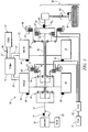
- FIG. 1 is a schematic diagram of an exemplary powertrain, in accordance with the present disclosure
- FIG. 2 is a schematic diagram of an exemplary architecture for a control system and powertrain, in accordance with the present disclosure
- FIG. 3 is a schematic diagram of a hydraulic circuit, in accordance with the present disclosure.
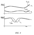
- FIG. 4 graphically depicts reaction times of exemplary hybrid powertrain components to changes in torque request, in accordance with the present disclosure
- FIG. 5 is a graphical representation of torque terms associated with a clutch through an exemplary transitional unlocking state, in accordance with the present disclosure
- FIG. 6 shows an exemplary control system architecture for controlling and managing torque and power flow in a powertrain system having multiple torque generative devices and residing in control modules in the form of executable algorithms and calibrations, in accordance with the present disclosure
- FIG. 8 is a flowchart demonstrating an exemplary process whereby limits may be imposed upon an engine and an electric machine, in accordance with the present disclosure.
- FIG. 1 depicts an exemplary electro-mechanical hybrid powertrain.
- the exemplary electro-mechanical hybrid powertrain in accordance with the present disclosure is depicted in FIG. 1 , comprising a two-mode, compound-split, electro-mechanical hybrid transmission 10 operatively connected to an engine 14 and first and second electric machines ('MG-A') 56 and ('MG-B') 72.
- the engine 14 and first and second electric machines 56 and 72 each generate power which can be transmitted to the transmission 10.
- the power generated by the engine 14 and the first and second electric machines 56 and 72 and transmitted to the transmission 10 is described in terms of input torques, referred to herein as T I , T A , and T B respectively, and speed, referred to herein as N I , N A , and N B , respectively.
- the exemplary engine 14 comprises a multi-cylinder internal combustion engine selectively operative in several states to transmit torque to the transmission 10 via an input shaft 12, and can be either a spark-ignition or a compression-ignition engine.
- the engine 14 includes a crankshaft (not shown) operatively coupled to the input shaft 12 of the transmission 10.
- a rotational speed sensor 11 monitors rotational speed of the input shaft 12.
- Power output from the engine 14, comprising rotational speed and output torque can differ from the input speed, N I , and the input torque, T I , to the transmission 10 due to placement of torque-consuming components on the input shaft 12 between the engine 14 and the transmission 10, e.g., a hydraulic pump (not shown) and/or a torque management device (not shown).
- the exemplary transmission 10 comprises three planetary-gear sets 24, 26 and 28, and four selectively engagable torque-transmitting devices, i.e., clutches C1 70, C2 62, C3 73, and C4 75.
- clutches refer to any type of friction torque transfer device including single or compound plate clutches or packs, band clutches, and brakes, for example.
- a hydraulic control circuit 42 preferably controlled by a transmission control module (hereafter 'TCM') 17, is operative to control clutch states.
- Clutches C2 62 and C4 75 preferably comprise hydraulically-applied rotating friction clutches.
- Clutches C1 70 and C3 73 preferably comprise hydraulically-controlled stationary devices that can be selectively grounded to a transmission case 68.
- Each of the clutches C1 70, C2 62, C3 73, and C4 75 is preferably hydraulically applied, selectively receiving pressurized hydraulic fluid via the hydraulic control circuit 42.
- the first and second electric machines 56 and 72 preferably comprise three-phase AC machines, each including a stator (not shown) and a rotor (not shown), and respective resolvers 80 and 82.
- the motor stator for each machine is grounded to an outer portion of the transmission case 68, and includes a stator core with coiled electrical windings extending therefrom.
- the rotor for the first electric machine 56 is supported on a hub plate gear that is operatively attached to shaft 60 via the second planetary gear set 26.
- the rotor for the second electric machine 72 is fixedly attached to a sleeve shaft hub 66.
- Each of the resolvers 80 and 82 preferably comprises a variable reluctance device including a resolver stator (not shown) and a resolver rotor (not shown).
- the resolvers 80 and 82 are appropriately positioned and assembled on respective ones of the first and second electric machines 56 and 72.
- Stators of respective ones of the resolvers 80 and 82 are operatively connected to one of the stators for the first and second electric machines 56 and 72.
- the resolver rotors are operatively connected to the rotor for the corresponding first and second electric machines 56 and 72.
- Each of the resolvers 80 and 82 is signally and operatively connected to a transmission power inverter control module (hereafter 'TPIM') 19, and each senses and monitors rotational position of the resolver rotor relative to the resolver stator, thus monitoring rotational position of respective ones of first and second electric machines 56 and 72. Additionally, the signals output from the resolvers 80 and 82 are interpreted to provide the rotational speeds for first and second electric machines 56 and 72, i.e., N A and N B , respectively.
- the transmission 10 includes an output member 64, e.g. a shaft, which is operably connected to a driveline 90 for a vehicle (not shown), to provide output power, e.g., to vehicle wheels 93, one of which is shown in FIG. 1 .
- the output power is characterized in terms of an output rotational speed, No and an output torque, To.
- a transmission output speed sensor 84 monitors rotational speed and rotational direction of the output member 64.
- Each of the vehicle wheels 93 is preferably equipped with a sensor 94 adapted to monitor wheel speed, V SS-WHL , the output of which is monitored by a control module of a distributed control module system described with respect to FIG. 2 , to determine vehicle speed, and absolute and relative wheel speeds for braking control, traction control, and vehicle acceleration management.
- the input torques from the engine 14 and the first and second electric machines 56 and 72 (T I , T A , and T B respectively) are generated as a result of energy conversion from fuel or electrical potential stored in an electrical energy storage device (hereafter 'ESD') 74.
- the ESD 74 is high voltage DC-coupled to the TPIM 19 via DC transfer conductors 27.
- the transfer conductors 27 include a contactor switch 38. When the contactor switch 38 is closed, under normal operation, electric current can flow between the ESD 74 and the TPIM 19. When the contactor switch 38 is opened electric current flow between the ESD 74 and the TPIM 19 is interrupted.
- the TPIM 19 transmits electrical power to and from the first electric machine 56 by transfer conductors 29, and the TPIM 19 similarly transmits electrical power to and from the second electric machine 72 by transfer conductors 31, in response to torque commands for the first and second electric machines 56 and 72 to achieve the input torques T A and T B . Electrical current is transmitted to and from the ESD 74 in accordance with whether the ESD 74 is being charged or discharged.
- the TPIM 19 includes the pair of power inverters (not shown) and respective motor control modules (not shown) configured to receive the torque commands and control inverter states therefrom for providing motor drive or regeneration functionality to meet the commanded motor torques T A and T B .
- the power inverters comprise known complementary three-phase power electronics devices, and each includes a plurality of insulated gate bipolar transistors (not shown) for converting DC power from the ESD 74 to AC power for powering respective ones of the first and second electric machines 56 and 72, by switching at high frequencies.
- the insulated gate bipolar transistors form a switch mode power supply configured to receive control commands. There is typically one pair of insulated gate bipolar transistors for each phase of each of the three-phase electric machines.
- the three-phase inverters receive or supply DC electric power via DC transfer conductors 27 and transform it to or from three-phase AC power, which is conducted to or from the first and second electric machines 56 and 72 for operation as motors or generators via transfer conductors 29 and 31 respectively.
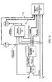
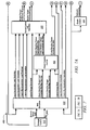
- FIG. 2 is a schematic block diagram of the distributed control module system.
- the elements described hereinafter comprise a subset of an overall vehicle control architecture, and provide coordinated system control of the exemplary powertrain described in FIG. 1 .
- the distributed control module system synthesizes pertinent information and inputs, and executes algorithms to control various actuators to achieve control objectives, including objectives related to fuel economy, emissions, performance, drivability, and protection of hardware, including batteries of ESD 74 and the first and second electric machines 56 and 72.
- the distributed control module system includes an engine control module (hereafter 'ECM') 23, the TCM 17, a battery pack control module (hereafter 'BPCM') 21, and the TPIM 19.
- 'ECM' engine control module
- TCM 17 battery pack control module
- TPIM 19 battery pack control module
- a hybrid control module (hereafter 'HCP') 5 provides supervisory control and coordination of the ECM 23, the TCM 17, the BPCM 21, and the TPIM 19.
- a user interface ('UI') 13 is operatively connected to a plurality of devices through which a vehicle operator controls or directs operation of the electro-mechanical hybrid powertrain.
- the devices include an accelerator pedal 113 ('AP') from which an operator torque request is determined, an operator brake pedal 112 ('BP'), a transmission gear selector 114 ('PRNDL'), and a vehicle speed cruise control (not shown).
- the transmission gear selector 114 may have a discrete number of operator-selectable positions, including the rotational direction of the output member 64 to enable one of a forward and a reverse direction.
- the aforementioned control modules communicate with other control modules, sensors, and actuators via a local area network (hereafter 'LAN') bus 6.
- the LAN bus 6 allows for structured communication of states of operating parameters and actuator command signals between the various control modules.
- the specific communication protocol utilized is application-specific.
- the LAN bus 6 and appropriate protocols provide for robust messaging and multi-control module interfacing between the aforementioned control modules, and other control modules providing functionality such as antilock braking, traction control, and vehicle stability.
- Multiple communications buses may be used to improve communications speed and provide some level of signal redundancy and integrity. Communication between individual control modules can also be effected using a direct link, e.g., a serial peripheral interface ('SPI') bus (not shown).
- 'SPI' serial peripheral interface
- the HCP 5 provides supervisory control of the powertrain, serving to coordinate operation of the ECM 23, TCM 17, TPIM 19, and BPCM 21. Based upon various input signals from the user interface 13 and the powertrain, including the ESD 74, the HCP 5 generates various commands, including: the operator torque request ('T O_REQ '), a commanded output torque ('T CMD ') to the driveline 90, an engine input torque command, clutch torques for the torque-transfer clutches C 1 70, C2 62, C3 73, C4 75 of the transmission 10; and the torque commands for the first and second electric machines 56 and 72, respectively.
- the TCM 17 is operatively connected to the hydraulic control circuit 42 and provides various functions including monitoring various pressure sensing devices (not shown) and generating and communicating control signals to various solenoids (not shown) thereby controlling pressure switches and control valves contained within the hydraulic control circuit 42.
- the ECM 23 is operatively connected to the engine 14, and functions to acquire data from sensors and control actuators of the engine 14 over a plurality of discrete lines, shown for simplicity as an aggregate bi-directional interface cable 35.
- the ECM 23 receives the engine input torque command from the HCP 5.
- the ECM 23 determines the actual engine input torque, T I , provided to the transmission 10 at that point in time based upon monitored engine speed and load, which is communicated to the HCP 5.
- the ECM 23 monitors input from the rotational speed sensor 11 to determine the engine input speed to the input shaft 12, which translates to the transmission input speed, N I .
- the ECM 23 monitors inputs from sensors (not shown) to determine states of other engine operating parameters including, e.g., a manifold pressure, engine coolant temperature, ambient air temperature, and ambient pressure.
- the engine load can be determined, for example, from the manifold pressure, or alternatively, from monitoring operator input to the accelerator pedal 113.
- the ECM 23 generates and communicates command signals to control engine actuators, including, e.g., fuel injectors, ignition modules, and throttle control modules, none of which are shown.
- the TCM 17 is operatively connected to the transmission 10 and monitors inputs from sensors (not shown) to determine states of transmission operating parameters.
- the TCM 17 generates and communicates command signals to control the transmission 10, including controlling the hydraulic circuit 42.
- Inputs from the TCM 17 to the HCP 5 include estimated clutch torques for each of the clutches, i.e., C 1 70, C2 62, C3 73, and C4 75, and rotational output speed, No, of the output member 64.
- Other actuators and sensors may be used to provide additional information from the TCM 17 to the HCP 5 for control purposes.
- the TCM 17 monitors inputs from pressure switches (not shown) and selectively actuates pressure control solenoids (not shown) and shift solenoids (not shown) of the hydraulic circuit 42 to selectively actuate the various clutches C1 70, C2 62, C3 73, and C4 75 to achieve various transmission operating range states, as described hereinbelow.
- the BPCM 21 is signally connected to sensors (not shown) to monitor the ESD 74, including states of electrical current and voltage parameters, to provide information indicative of parametric states of the batteries of the ESD 74 to the HCP 5.
- the parametric states of the batteries preferably include battery state-of-charge, battery voltage, battery temperature, and available battery power, referred to as a range P BAT_MIN to P BAT_MAX .
- Each of the control modules ECM 23, TCM 17, TPIM 19 and BPCM 21 is preferably a general-purpose digital computer comprising a microprocessor or central processing unit, storage mediums comprising read only memory ('ROM'), random access memory ('RAM'), electrically programmable read only memory ('EPROM'), a high speed clock, analog to digital ('A/D') and digital to analog ('D/A') circuitry, and input/output circuitry and devices ('I/O') and appropriate signal conditioning and buffer circuitry.
- Each of the control modules has a set of control algorithms, comprising resident program instructions and calibrations stored in one of the storage mediums and executed to provide the respective functions of each computer.
- control algorithms are executed during preset loop cycles such that each algorithm is executed at least once each loop cycle.
- Algorithms stored in the non-volatile memory devices are executed by one of the central processing units to monitor inputs from the sensing devices and execute control and diagnostic routines to control operation of the actuators, using preset calibrations.
- Loop cycles are executed at regular intervals, for example each 3.125, 6.25, 12.5, 25 and 100 milliseconds during ongoing operation of the powertrain. Alternatively, algorithms may be executed in response to the occurrence of an event.
- the exemplary powertrain selectively operates in one of several operating range states that can be described in terms of an engine state comprising one of an engine on state ('ON') and an engine off state ('OFF'), and a transmission state comprising a plurality of fixed gears and continuously variable operating modes, described with reference to Table 1, below.
- a third fixed gear operation ('FG3') is selected by applying clutches C2 62 and C4 75.
- a fourth fixed gear operation ('FG4') is selected by applying clutches C2 62 and C3 73.
- the fixed ratio operation of input-to-output speed increases with increased fixed gear operation due to decreased gear ratios in the planetary gears 24, 26, and 28.
- the rotational speeds of the first and second electric machines 56 and 72, N A and N B respectively, are dependent on internal rotation of the mechanism as defined by the clutching and are proportional to the input speed measured at the input shaft 12.
- the HCP 5 and one or more of the other control modules determine the commanded output torque, T CMD , intended to meet the operator torque request, T O_REQ , to be executed at the output member 64 and transmitted to the driveline 90.
- Final vehicle acceleration is affected by other factors including, e.g., road load, road grade, and vehicle mass.
- the operating range state is determined for the transmission 10 based upon a variety of operating characteristics of the powertrain. This includes the operator torque request, communicated through the accelerator pedal 113 and brake pedal 112 to the user interface 13 as previously described.
- the operating range state may be predicated on a powertrain torque demand caused by a command to operate the first and second electric machines 56 and 72 in an electrical energy generating mode or in a torque generating mode.
- the operating range state can be determined by an optimization algorithm or routine which determines optimum system efficiency based upon operator demand for power, battery state of charge, and energy efficiencies of the engine 14 and the first and second electric machines 56 and 72.
- the control system manages torque inputs from the engine 14 and the first and second electric machines 56 and 72 based upon an outcome of the executed optimization routine, and system efficiencies are optimized thereby, to manage fuel economy and battery charging. Furthermore, operation can be determined based upon a fault in a component or system.
- the HCP 5 monitors the torque-generative devices, and determines the power output from the transmission 10 required to achieve the desired output torque to meet the operator torque request.
- the ESD 74 and the first and second electric machines 56 and 72 are electrically-operatively coupled for power flow therebetween.
- the engine 14, the first and second electric machines 56 and 72, and the electro-mechanical transmission 10 are mechanically-operatively coupled to transmit power therebetween to generate a power flow to the output member 64.
- FIG. 3 depicts a schematic diagram of the hydraulic circuit 42 for controlling flow of hydraulic fluid in the exemplary transmission.
- a main hydraulic pump 88 is driven off the input shaft 12 from the engine 14, and an auxiliary pump 110 controlled by the TPIM 19 to provide pressurized fluid to the hydraulic circuit 42 through valve 140.
- the auxiliary pump 110 preferably comprises an electrically-powered pump of an appropriate size and capacity to provide sufficient flow of pressurized hydraulic fluid into the hydraulic circuit 42 when operational.
- the controllable pressure regulator 107 and spool valve 109 interact with PCS1 108 to control hydraulic pressure in the hydraulic circuit 42 over a range of pressures and may provide additional functionality for the hydraulic circuit 42.
- Pressure control solenoid PCS3 112 has a control position of normally high, and is fluidly connected to spool valve 113 and operative to effect flow therethrough when actuated.
- Spool valve 113 is fluidly connected to pressure switch PS3 via passage 126.
- Pressure control solenoid PCS2 114 has a control position of normally high, and is fluidly connected to spool valve 115 and operative to effect flow therethrough when actuated.
- Spool valve 115 is fluidly connected to pressure switch PS2 via passage 124.
- Pressure control solenoid PCS4 116 has a control position of normally low, and is fluidly connected to spool valve 117 and operative to effect flow therethrough when actuated.
- Spool valve 117 is fluidly connected to pressure switch PS4 via passage 128.
- the X-Valve 119 and Y-Valve 121 each comprise flow management valves controlled by solenoids 118, 120, respectively, in the exemplary system, and have control states of High ('1') and Low ('0').
- the control states refer to positions of each valve to which control flow to different devices in the hydraulic circuit 42 and the transmission 10.
- the X-valve 119 is operative to direct pressurized fluid to clutches C3 73 and C4 75 and cooling systems for stators of the first and second electric machines 56 and 72 via fluidic passages 136, 138, 144, 142 respectively, depending upon the source of the fluidic input, as is described hereinafter.
- the hydraulic circuit 42 includes a base cooling circuit for providing hydraulic fluid to cool the stators of the first and second electric machines 56 and 72.
- the base cooling circuit includes fluid conduits from the valve 140 flowing directly to a flow restrictor which leads to fluidic passage 144 leading to the base cooling circuit for the stator of the first electric machine 56, and to a flow restrictor which leads to fluidic passage 142 leading to the base cooling circuit for the stator of the second electric machine 72.
- Active cooling of stators for the first and second electric machines 56 and 72 is effected by selective actuation of pressure control solenoids PCS2 114, PCS3 112 and PCS4 116 and solenoid-controlled flow management valves X-valve 119 and Y-valve 121, which leads to flow of hydraulic fluid around the selected stator and permits heat to be transferred therebetween, primarily through conduction.
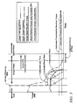
- Table 2 An exemplary logic table to accomplish control of the exemplary hydraulic control circuit 42 to control operation of the transmission 10 in one of the transmission operating range states is provided with reference to Table 2, below.
- Table 2 X-Valve Logic Y-Valve Logic PCS1 PCS2 PCS3 PCS4 Transmis -sion Operating Range State No Latch C2 Latch Normal High Normal High Normal High Normal Low EVT Mode I 0 0 Line Modulation MG-B Stator Cool C1 MG-A Stator Cool EVT Mode II 0 1 Line Modulation C2 MG-B Stator Cool MG-A Stator Cool Low Range 1 0 Line Modulation C2 C1 C4 High Range 1 1 Line Modulation C2 C3 C4
- a Low Range is defined as a transmission operating range state comprising one of the first continuously variable mode and the first and second fixed gear operations.
- a High Range is defined as a transmission operating range state comprising one of the second continuously variable mode and the third and fourth fixed gear operations.
- a transmission operating range state i.e. one of the fixed gear and continuously variable mode operations, is selected for the exemplary transmission 10 based upon a variety of operating characteristics of the powertrain. This includes the operator torque request, typically communicated through inputs to the UI 13 as previously described. Additionally, a demand for output torque is predicated on external conditions, including, e.g., road grade, road surface conditions, or wind load.
- the operating range state may be predicated on a powertrain torque demand caused by a control module command to operate of the electrical machines in an electrical energy generating mode or in a torque generating mode.
- the operating range state can be determined by an optimization algorithm or routine operable to determine an optimum system efficiency based upon the operator torque request, battery state of charge, and energy efficiencies of the engine 14 and the first and second electric machines 56 and 72.
- the control system manages the input torques from the engine 14 and the first and second electric machines 56 and 72 based upon an outcome of the executed optimization routine, and system optimization occurs to improve fuel economy and manage battery charging. Furthermore, the operation can be determined based upon a fault in a component or system.
- clutch slip is an event which occurs when the load or reactive torque applied across a clutch exceeds an actual torque capacity of the clutch.
- the torque applied overcomes static frictional forces between the connective surfaces of the clutch, and the connective surfaces rotate relative to each other.
- clamping force is necessarily transitioned rapidly from a high clamping force, at least sufficient to maintain the previous locked state, to a low or null clamping force sufficient to create an unlocked state.
- the reactive torque must be rapidly decreased to avoid slip.
- Slip created in an unlocking event creates variability it the torque transmitted through the transitioning clutch and can also create variability in the torque transmitted through other clutches in the vehicle.
- a method is disclosed to prevent slip within a clutch in an unlocking state by imposing torque constraints upon the engine and electrical machines applying torque to the clutch, thereby progressively eliminating applied reactive torque, and simultaneously maintaining torque capacity of the clutch in excess of the torque constraints throughout the unlocking state.
- any control system includes a reaction time. Changes to a powertrain operating point, comprising the speeds and torques of the various components to the powertrain required to achieve the desired vehicle operation, are driven by changes in control signals. These control signal changes act upon the various components to the powertrain and create reactions in each according to their respective reaction times. Applied to a hybrid powertrain, any change in control signals indicating a new torque request, for instance, as driven by a change in operator torque request or as required to execute a transmission shift, creates reactions in each affected torque generating device in order to execute the required changes to respective input torques. Changes to input torque supplied from an engine are controlled by an engine torque request setting the torque generated by the engine, as controlled, for example, through an ECM.
- Reaction time within an engine to changes in torque request to an engine is impacted by a number of factors well known in the art, and the particulars of a change to engine operation depend heavily on the particulars of the engine employed and the mode or modes of combustion being utilized. In many circumstances, the reaction time of an engine to changes in torque request will be the longest reaction time of the components to the hybrid drive system. Reaction time within an electric machine to changes in torque request include time to activate any necessary switches, relays, or other controls and time to energize or de-energize the electric machine with the change in applied electrical power.
- FIG. 4 graphically depicts reaction times of exemplary hybrid powertrain components to changes in torque request, in accordance with the present disclosure.
- Components to an exemplary hybrid powertrain system including an engine and two electric machines are exemplified. Torque requests and resulting changes in input torque produced by each torque generating device are illustrated. As described above, the data shows that electric machines quickly respond to changes in torque requests, whereas the engine follows changes in torque requests more slowly.
- a method is disclosed wherein reactions times of the engine and of the electric machine or machines within a hybrid powertrain are utilized to control in parallel a lead immediate torque request, controlling the engine, and an immediate torque request, controlling the electric machines, the torque requests being coordinated by respective reaction times in order to substantially effect simultaneous changes to input torque.
- an exemplary embodiment of the disclosed method can implement changes in torque request to the engine and the electric machine, acting in parallel as described above, including a lead period to the more quickly reacting device, the electric motor.
- This lead period may be developed experimentally, empirically, predictively, through modeling or other techniques adequate to accurately predict engine and electric machine operation, and a multitude of lead periods might be used by the same hybrid powertrain, depending upon different engine settings, conditions, operating and ranges and vehicle conditions.
- An exemplary equation that can be used in conjunction with test data or estimates of device reaction times to calculate lead period in accordance with the present disclosure includes the following relationship.
- T Lead T Lead Reaction - T Immediate Reaction
- T Lead equals the lead period for use in methods described herein. This equation assumes that two torque producing devices are utilized. T Lead Reaction represents the reaction time of the device with the longer reaction time, and T Immediate Reaction represents the reaction time of the device with the shorter reaction time. If a different system is utilized, comprising for example, an engine with a long lead period, a first electric machine with an intermediate lead period, and a second electric machine with a short lead period, lead periods can be developed comparing all of the torque generating devices. In this exemplary system, if all three torque generating devices are involved, two lead periods, one for the engine as compared to each of the electric machines, will be utilized to synchronize the responses in each of the devices.
- the same system at a different time might be operating with the engine off and disengaged from the transmission, and a lead period comparing the first electric machine and the second electric machine will be utilized to synchronize the responses in the two electric machines. In this way, a lead period can be developed coordinating reaction times between various torque generating devices can be developed.
- One exemplary method to utilize lead periods to implement parallel torque requests to distinct torque generating devices in order to effect substantially simultaneous changes to output torque in response to a change in operator torque request includes issuing substantially immediately a change to the engine torque immediate request, initiating within the engine a change to a new engine output torque.
- This new engine output torque in conjunction with the electric motor operating state, is still managed by the HCP in order to provide some portion of the total input torque to the transmission required to propel the vehicle. From the point that the engine torque immediate request changes, the lead period expires, described above taking into account the differences in reaction times between the engine and the electric machine.
- engine torque immediate requests and torque requests to an electric machine are disclosed for use in parallel to control distinct torque generative devices with different reaction times to reaction to changes in operator torque request.
- Changes in operator torque request can include a simple change in desired output torque within a particular transmission operating range state, or changes in operator torque request can be required in conjunction with a transmission shift between different operating range states.
- Changes to operator torque requests in conjunction with a transmission shift are more complex than changes contained within a single operating range state because torques and shaft speeds of the various hybrid powertrain components must be managed in order to transition torque applied from a first clutch and to a second previously not applied clutch without the occurrence of slip, as described above.
- An unlocking state requiring controlled reactions within the clutch as a reduction in clamping force, within the engine as a reduction in input torque, and within the electric machine as a reduction in electric machine torque, must balance the reaction times of the torque generative devices of the powertrain in order to simultaneously affect changes to output torque and to maintain the torque capacity of the clutch above the applied reactive torque.
- Reductions in torque capacity of a clutch are controlled by a commanded torque from the clutch control system. Reaction time within a clutch to changes in commanded torque is impacted by a number of factors, including the particulars of the clutch design and the control method of the clutch control system.
- contributors to reaction time include time required to activate solenoids and valves controlling hydraulic pressures and time required for hydraulic flow in the hydraulic medium to propagate through connected circuits.
- reaction times of the various hybrid drive components to an initiation of the unlocking state must be compared, and the torque capacity of the clutch must be maintained at a minimum level adequately above reactive torque levels to prevent slip until the reaction times of the torque producing components are accommodated through a lead period sufficient to allow for the reduction of reactive torque in the clutch.
- the minimum level of torque capacity necessary to prevent slip can be set to some value just exceeding the estimated level of reactive torque transmitted through the clutch.
- reactive torque transmitted through the clutch and torque capacity resulting from a clutch torque command are both estimated values that cannot be measured directly during vehicle operation.
- a safety margin or offset value can be used to maintain the torque capacity above the reactive torque. Therefore, preventing clutch slip according the described method can be accomplished in one exemplary embodiment by maintaining torque capacity above reactive torque transmitted through the clutch by at least an offset value calibrated to the particular reaction times within the hybrid drive system.
- FIG. 5 is a graphical representation of torque terms associated with a clutch through an exemplary transitional unlocking state in accordance with the present disclosure.
- Lines illustrated at the left extreme of the graph depict clutch operation in a locked state.
- the graph depicts clutch torque command by the clutch control system and a resulting torque capacity estimate.
- Clutch torque command is a value requested by the clutch control system.
- Torque capacity estimate in a clutch resulting from a commanded torque is a result of many factors, including available clamping pressure, design and conditional factors of the clutch, reaction time in the clutch to changes in the clutch control system.
- torque capacity estimate of the clutch begins to change as the clamping force applied to the clutch changes.
- the clutch reacts to a change in clutch torque command over a reaction time, and reaction time for a particular clutch will depend upon the particulars of the application.
- torque capacity estimate reacts to a reduction in commanded torque and begins to reduce accordingly.
- clutch reactive torque resulting from input torque and electric machine torques must also be unloaded from the clutch. Undesirable slip results if the reactive torque is not maintained below the torque capacity throughout the unlocking state.
- limits are initiated upon input torque in the form of a clutch reactive torque lead immediate maximum override.
- a clutch reactive torque immediate maximum override is implemented, controlling electric machine torque to both constrain electric machine torque and to utilize the quick reaction time of the electric machines to additionally constrain input torque from the engine, if needed to keep clutch reactive torque estimate below the torque capacity estimate.
- the input torque and electric machine torque or torques together provide, each up to the defined maximum values, the portion of the powertrain torque demand assigned to the clutch, described by the clutch reactive torque estimate.
- the lines indicated for clutch reactive torque lead immediate maximum override and clutch reactive torque immediate maximum override illustrate the commands and not the actual changes in torque
- the ramping down of input torque command by the clutch reactive torque lead immediate maximum override, depicted on the chart before the ramping down of electric machine torque command by the clutch reactive torque immediate maximum override illustrates necessary lead period between the reducing commands in order to enact substantially simultaneous reductions in reactive torque.
- the clutch reactive torque lead immediate maximum is ramped down in lead period
- the clutch reactive torque immediate maximum is ramped down in a second period following the lead period.
- the initial reduction in clutch torque command to some level above the actual clutch reactive torque initiates a reduction in torque capacity estimate, to some intermediate level lower than the maximum torque capacity utilized in a locked state, in preparation to reduce the torque capacity estimate to zero to complete the transition to the unlocked state.
- the above described process is utilized to reduce reactive torque transmitted through the clutch, initiating a lead period calibrated to the reaction time of the engine to torque commands, the commanded clutch torque remains steadily above the actual clutch reactive torque in order to eliminate potential for slip.
- the above exemplary process maintains the clutch reactive torque immediate maximum override through the lead period.
- One method to safeguard the ramp rates and prevent slip is to set the clutch torque command to be no smaller than the clutch reactive torque estimate until the clutch reactive torque estimate drops below a particular threshold, as is demonstrated by the horizontal calibrated threshold for reactive torque depicted in FIG. 5 .
- Another method to safeguard the ramp rates and prevent slip is set the clutch torque command according to either the clutch reactive torque immediate maximum override or the clutch reactive torque estimate, requiring the clutch torque command to exceed either value by a calibrated ramp offset value.
- a strategic optimization control scheme ('Strategic Control') 310 determines a preferred input speed ('N I_DES ') and a preferred engine state and transmission operating range state ('Hybrid Range State Des') based upon the output speed and the operator torque request, and optimized based upon other operating parameters of the hybrid powertrain, including battery power limits and response limits of the engine 14, the transmission 10, and the first and second electric machines 56 and 72.
- the strategic optimization control scheme 310 is preferably executed by the HCP 5 during each 100 ms loop cycle and each 25 ms loop cycle.
- the outputs of the strategic optimization control scheme 310 are used in a shift execution and engine start/stop control scheme ('Shift Execution and Engine Start/Stop') 320 to command changes in the transmission operation ('Transmission Commands') including changing the operating range state.
- the present operating range state ('Hybrid Range State Actual') and an input speed profile ('N I_PROF ') can be determined.
- a tactical control scheme ('Tactical Control and Operation') 330 is repeatedly executed during one of the control loop cycles to determine engine commands ('Engine Commands') for operating the engine, including a preferred input torque from the engine 14 to the transmission 10 based upon the output speed, the input speed, and the operator torque request and the present operating range state for the transmission.
- the engine commands also include engine states including one of an all-cylinder operating state and a cylinder deactivation operating state wherein a portion of the engine cylinders are deactivated and unfueled, and engine states including one of a fueled state and a fuel cutoff state.
- the preferred output torque is based upon the estimated clutch torque(s) for each of the clutches, the present input torque from the engine 14, the present operating range state, the input speed, the operator torque request, and the input speed profile.
- the first and second electric machines 56 and 72 are controlled through the TPIM 19 to meet the preferred motor torque commands based upon the preferred output torque.
- the motor torque control scheme 340 includes algorithmic code which is regularly executed during the 6.25 ms and 12.5 ms loop cycles to determine the preferred motor torque commands.
- FIG. 7 is a schematic diagram exemplifying data flow through a shift execution, describing more detail exemplary execution of the control system architecture such as the system of FIG. 6 in greater detail, in accordance with the present disclosure.
- Powertrain control system 400 is illustrated comprising several hybrid drive components, including an engine 410, an electric machine 420, and clutch hydraulics 430.
- Control modules strategic control module 310, shift execution module 450, clutch capacity control module 460, tactical control and operation module 330, output and motor torque determination module 340, and clutch control module 490, are illustrated, processing information and issuing control commands to engine 410, electric machine 420, and clutch hydraulics 430.
- control modules can be physically separate, can be grouped together in a number of different control devices, or can be entirely performed within a single physical control device.
- Module 310 a strategic control module, performs determinations regarding preferred powertrain operating points and preferred operating range states as described in FIG. 6 .
- Module 450 a shift execution module, receives input from strategic control module 310 and other sources regarding shift initiation. Module 450 processes inputs regarding the reactive torque currently applied to the clutch and the preferred operating range state to be transitioned to.
- Module 450 then employs programming, determining parameters for the execution of the shift, including hybrid range state parameters describing the balance of input torques required of the torque providing devices, details regarding a target input speed and input acceleration lead predicted required to execute the transition to the preferred operating range state, an input acceleration lead immediate as previously described, and clutch reactive torque lead immediate minimum and maximum and clutch reactive torque immediate minimum and maximum values as previously described.
- clutch reactive torque parameters and hybrid range state information are fed to clutch capacity control module 460, lead control parameters and signals are fed to tactical control and operation module 330, and immediate control parameters and signals are fed to output and motor torque determination module 340.
- Module 490 processes information from modules 460 and 340 and issues hydraulic commands in order to achieve the required clutch torque capacity required to operate the transmission.
- This particular embodiment of data flow illustrates one possible exemplary process by which a vehicular torque generative devices and related clutches can be controlled in accordance with the method disclosed herein. It will be appreciated by one having ordinary skill in the art that the particular process employed can vary, and this disclosure is not intended to limited to the particular exemplary embodiment described herein.
- FIG. 8 is a flowchart demonstrating an exemplary process whereby limits may be imposed upon an engine and electric machine in accordance with the present disclosure.
- a clutch reactive torque lead immediate maximum override and a clutch reactive torque immediate maximum override are defined and eventually ramped down to zero for purposes of unloading reactive torque from a clutch.
- the process begins.
- a timer is implemented in order to effect a calibrated delay, as described above, in order to utilize a lead period and coordinate overriding torque commands to the engine.
- the clutch reactive torque lead immediate maximum override is set to an initial clutch reactive torque estimate value calculated at the initiation of the unlocking state.
- the clutch reactive torque immediate maximum override is set to the initial clutch reactive torque estimate value.
- the clutch reactive torque lead immediate maximum override is decreased incrementally by a calibrated ramp rate.
- the clutch reactive torque lead immediate maximum override is examined, and if the value is less than zero, then the process proceeds to step 214. If the value is not less than zero, then the process proceeds to step 216.
- the clutch reactive torque lead immediate maximum override found to be negative at step 212, is set to zero.
- a value from the timer initiated at step 204 is compared to a lead period. If the timer has exceeded the lead period, then the process proceeds to step 220.
- step 218 the process still being within the lead period, the clutch reactive torque immediate maximum override is set to the initial clutch reactive torque estimate.
- step 220 the process having exceeded the lead period, the clutch reactive torque immediate maximum override is decreased incrementally by a calibrated ramp rate.
- step 222 the clutch reactive torque immediate maximum override is examined, and if the value is less than zero, then the process proceeds to step 224. If the value is not less than zero, then the process proceeds to step 226.
- step 224 the clutch reactive torque immediate maximum override, found to be negative at step 222, is set to zero.
- the clutch reactive torque estimate is examined, and if the value is less than a threshold, then the process proceeds to step 230. If the value is not less than a threshold, then the process proceeds to step 228.
- the clutch torque command in an exemplary method to reduce the clutch torque as the clutch reactive torque estimate is being ramped down, is set to the clutch reactive torque estimate plus an offset value.
- the clutch torque command is set to zero and the clutch is substantially commanded to an unlocked state.
- the clutch reactive torque estimate is examined, and if the value is less than a threshold for a set period, then the process is ended.
- step 210 the torques transmitted through a clutch in the form of an input torque and an electric machine torque or torques can be limited and ramped down to zero for the purpose of unloading the clutch.
- the above method describes a process for transitioning a single clutch from a locked state to an unlocked state.
- a plurality of clutches can be substantially simultaneously transitioned, wherein all of the clutch torque capacities are coordinated with an input torque and an electric machine torque or torques to prevent slip, for instance, if a vehicle has been shifted by the operator into a neutral gear state.
- each clutch can be individually controlled, with each clutch's torque capacity being maintained in excess of an estimated reactive torque for each clutch through a common lead period calibrated to the response time of the vehicle engine.
Landscapes
- Engineering & Computer Science (AREA)
- Chemical & Material Sciences (AREA)
- Combustion & Propulsion (AREA)
- Transportation (AREA)
- Mechanical Engineering (AREA)
- Automation & Control Theory (AREA)
- Hybrid Electric Vehicles (AREA)
- Electric Propulsion And Braking For Vehicles (AREA)
- Control Of Vehicle Engines Or Engines For Specific Uses (AREA)
- Control Of Driving Devices And Active Controlling Of Vehicle (AREA)
Applications Claiming Priority (2)
| Application Number | Priority Date | Filing Date | Title |
|---|---|---|---|
| US98246307P | 2007-10-25 | 2007-10-25 | |
| US12/248,199 US8296027B2 (en) | 2007-10-25 | 2008-10-09 | Method and apparatus to control off-going clutch torque during torque phase for a hybrid powertrain system |
Publications (3)
| Publication Number | Publication Date |
|---|---|
| EP2052933A2 true EP2052933A2 (de) | 2009-04-29 |
| EP2052933A3 EP2052933A3 (de) | 2012-04-04 |
| EP2052933B1 EP2052933B1 (de) | 2013-07-03 |
Family
ID=40371619
Family Applications (1)
| Application Number | Title | Priority Date | Filing Date |
|---|---|---|---|
| EP08018704.0A Ceased EP2052933B1 (de) | 2007-10-25 | 2008-10-24 | Verfahren und Vorrichtung zur Kontrolle eines abweichenden Kupplungsdrehmoments während der Drehmomentphase für eine Hybridübertragungssystem |
Country Status (3)
| Country | Link |
|---|---|
| US (1) | US8296027B2 (de) |
| EP (1) | EP2052933B1 (de) |
| CN (1) | CN101440870B (de) |
Cited By (2)
| Publication number | Priority date | Publication date | Assignee | Title |
|---|---|---|---|---|
| WO2014029595A1 (de) * | 2012-08-20 | 2014-02-27 | Bayerische Motoren Werke Aktiengesellschaft | Verfahren zum zugkraftunterbrechungsfreien schalten eines automatikhybridgetriebes sowie automatikhybridgetriebe |
| EP3401156A4 (de) * | 2016-03-30 | 2019-01-16 | Honda Motor Co., Ltd. | Antriebsvorrichtung |
Families Citing this family (130)
| Publication number | Priority date | Publication date | Assignee | Title |
|---|---|---|---|---|
| US7585249B2 (en) * | 2006-06-30 | 2009-09-08 | Gm Global Technology Operations, Inc. | Apparatus and method to control transmission torque output during a gear-to-gear shift |
| US8390240B2 (en) * | 2007-08-06 | 2013-03-05 | GM Global Technology Operations LLC | Absolute position sensor for field-oriented control of an induction motor |
| US7867135B2 (en) | 2007-09-26 | 2011-01-11 | GM Global Technology Operations LLC | Electro-mechanical transmission control system |
| US8234048B2 (en) * | 2007-10-19 | 2012-07-31 | GM Global Technology Operations LLC | Method and system for inhibiting operation in a commanded operating range state for a transmission of a powertrain system |
| US9140337B2 (en) * | 2007-10-23 | 2015-09-22 | GM Global Technology Operations LLC | Method for model based clutch control and torque estimation |
| US8060267B2 (en) * | 2007-10-23 | 2011-11-15 | GM Global Technology Operations LLC | Method for controlling power flow within a powertrain system |
| US8265821B2 (en) * | 2007-10-25 | 2012-09-11 | GM Global Technology Operations LLC | Method for determining a voltage level across an electric circuit of a powertrain |
| US8187145B2 (en) * | 2007-10-25 | 2012-05-29 | GM Global Technology Operations LLC | Method and apparatus for clutch torque control in mode and fixed gear for a hybrid powertrain system |
| US8118122B2 (en) * | 2007-10-25 | 2012-02-21 | GM Global Technology Operations LLC | Method and system for monitoring signal integrity in a distributed controls system |
| US8335623B2 (en) * | 2007-10-25 | 2012-12-18 | GM Global Technology Operations LLC | Method and apparatus for remediation of and recovery from a clutch slip event in a hybrid powertrain system |
| US8548703B2 (en) | 2007-10-26 | 2013-10-01 | GM Global Technology Operations LLC | Method and apparatus to determine clutch slippage in an electro-mechanical transmission |
| US8560191B2 (en) | 2007-10-26 | 2013-10-15 | GM Global Technology Operations LLC | Method and apparatus to control clutch pressures in an electro-mechanical transmission |
| US7985154B2 (en) * | 2007-10-26 | 2011-07-26 | GM Global Technology Operations LLC | Method and apparatus to control hydraulic pressure for component lubrication in an electro-mechanical transmission |
| US8303463B2 (en) * | 2007-10-26 | 2012-11-06 | GM Global Technology Operations LLC | Method and apparatus to control clutch fill pressure in an electro-mechanical transmission |
| US8167773B2 (en) | 2007-10-26 | 2012-05-01 | GM Global Technology Operations LLC | Method and apparatus to control motor cooling in an electro-mechanical transmission |
| US8204702B2 (en) * | 2007-10-26 | 2012-06-19 | GM Global Technology Operations LLC | Method for estimating battery life in a hybrid powertrain |
| US8406945B2 (en) * | 2007-10-26 | 2013-03-26 | GM Global Technology Operations LLC | Method and apparatus to control logic valves for hydraulic flow control in an electro-mechanical transmission |
| US9097337B2 (en) | 2007-10-26 | 2015-08-04 | GM Global Technology Operations LLC | Method and apparatus to control hydraulic line pressure in an electro-mechanical transmission |
| US8244426B2 (en) * | 2007-10-27 | 2012-08-14 | GM Global Technology Operations LLC | Method and apparatus for monitoring processor integrity in a distributed control module system for a powertrain system |
| US8062174B2 (en) * | 2007-10-27 | 2011-11-22 | GM Global Technology Operations LLC | Method and apparatus to control clutch stroke volume in an electro-mechanical transmission |
| US8099219B2 (en) | 2007-10-27 | 2012-01-17 | GM Global Technology Operations LLC | Method and apparatus for securing an operating range state mechanical transmission |
| US8428816B2 (en) * | 2007-10-27 | 2013-04-23 | GM Global Technology Operations LLC | Method and apparatus for monitoring software and signal integrity in a distributed control module system for a powertrain system |
| US8170762B2 (en) | 2007-10-29 | 2012-05-01 | GM Global Technology Operations LLC | Method and apparatus to control operation of a hydraulic pump for an electro-mechanical transmission |
| US8489293B2 (en) * | 2007-10-29 | 2013-07-16 | GM Global Technology Operations LLC | Method and apparatus to control input speed profile during inertia speed phase for a hybrid powertrain system |
| US8112194B2 (en) * | 2007-10-29 | 2012-02-07 | GM Global Technology Operations LLC | Method and apparatus for monitoring regenerative operation in a hybrid powertrain system |
| US8290681B2 (en) * | 2007-10-29 | 2012-10-16 | GM Global Technology Operations LLC | Method and apparatus to produce a smooth input speed profile in mode for a hybrid powertrain system |
| US8095254B2 (en) * | 2007-10-29 | 2012-01-10 | GM Global Technology Operations LLC | Method for determining a power constraint for controlling a powertrain system |
| US8282526B2 (en) * | 2007-10-29 | 2012-10-09 | GM Global Technology Operations LLC | Method and apparatus to create a pseudo torque phase during oncoming clutch engagement to prevent clutch slip for a hybrid powertrain system |
| US8209098B2 (en) * | 2007-10-29 | 2012-06-26 | GM Global Technology Operations LLC | Method and apparatus for monitoring a transmission range selector in a hybrid powertrain transmission |
| US8145375B2 (en) * | 2007-11-01 | 2012-03-27 | GM Global Technology Operations LLC | System constraints method of determining minimum and maximum torque limits for an electro-mechanical powertrain system |
| US8556011B2 (en) * | 2007-11-01 | 2013-10-15 | GM Global Technology Operations LLC | Prediction strategy for thermal management and protection of power electronic hardware |
| US8035324B2 (en) * | 2007-11-01 | 2011-10-11 | GM Global Technology Operations LLC | Method for determining an achievable torque operating region for a transmission |
| US7977896B2 (en) | 2007-11-01 | 2011-07-12 | GM Global Technology Operations LLC | Method of determining torque limit with motor torque and battery power constraints |
| US8073602B2 (en) * | 2007-11-01 | 2011-12-06 | GM Global Technology Operations LLC | System constraints method of controlling operation of an electro-mechanical transmission with an additional constraint range |
| US8121765B2 (en) * | 2007-11-02 | 2012-02-21 | GM Global Technology Operations LLC | System constraints method of controlling operation of an electro-mechanical transmission with two external input torque ranges |
| US8847426B2 (en) | 2007-11-02 | 2014-09-30 | GM Global Technology Operations LLC | Method for managing electric power in a powertrain system |
| US8131437B2 (en) * | 2007-11-02 | 2012-03-06 | GM Global Technology Operations LLC | Method for operating a powertrain system to transition between engine states |
| US8287426B2 (en) * | 2007-11-02 | 2012-10-16 | GM Global Technology Operations LLC | Method for controlling voltage within a powertrain system |
| US8170764B2 (en) | 2007-11-02 | 2012-05-01 | GM Global Technology Operations LLC | Method and apparatus to reprofile input speed during speed during speed phase during constrained conditions for a hybrid powertrain system |
| US8121767B2 (en) * | 2007-11-02 | 2012-02-21 | GM Global Technology Operations LLC | Predicted and immediate output torque control architecture for a hybrid powertrain system |
| US8585540B2 (en) | 2007-11-02 | 2013-11-19 | GM Global Technology Operations LLC | Control system for engine torque management for a hybrid powertrain system |
| US8224539B2 (en) | 2007-11-02 | 2012-07-17 | GM Global Technology Operations LLC | Method for altitude-compensated transmission shift scheduling |
| US8200403B2 (en) | 2007-11-02 | 2012-06-12 | GM Global Technology Operations LLC | Method for controlling input torque provided to a transmission |
| US8825320B2 (en) * | 2007-11-02 | 2014-09-02 | GM Global Technology Operations LLC | Method and apparatus for developing a deceleration-based synchronous shift schedule |
| US8133151B2 (en) * | 2007-11-02 | 2012-03-13 | GM Global Technology Operations LLC | System constraints method of controlling operation of an electro-mechanical transmission with an additional constraint |
| US8260511B2 (en) * | 2007-11-03 | 2012-09-04 | GM Global Technology Operations LLC | Method for stabilization of mode and fixed gear for a hybrid powertrain system |
| US8010247B2 (en) | 2007-11-03 | 2011-08-30 | GM Global Technology Operations LLC | Method for operating an engine in a hybrid powertrain system |
| US8204664B2 (en) | 2007-11-03 | 2012-06-19 | GM Global Technology Operations LLC | Method for controlling regenerative braking in a vehicle |
| US8285431B2 (en) | 2007-11-03 | 2012-10-09 | GM Global Technology Operations LLC | Optimal selection of hybrid range state and/or input speed with a blended braking system in a hybrid electric vehicle |
| US8068966B2 (en) | 2007-11-03 | 2011-11-29 | GM Global Technology Operations LLC | Method for monitoring an auxiliary pump for a hybrid powertrain |
| US8296021B2 (en) | 2007-11-03 | 2012-10-23 | GM Global Technology Operations LLC | Method for determining constraints on input torque in a hybrid transmission |
| US8002667B2 (en) * | 2007-11-03 | 2011-08-23 | GM Global Technology Operations LLC | Method for determining input speed acceleration limits in a hybrid transmission |
| US8135526B2 (en) * | 2007-11-03 | 2012-03-13 | GM Global Technology Operations LLC | Method for controlling regenerative braking and friction braking |
| US8155814B2 (en) | 2007-11-03 | 2012-04-10 | GM Global Technology Operations LLC | Method of operating a vehicle utilizing regenerative braking |
| US8224514B2 (en) * | 2007-11-03 | 2012-07-17 | GM Global Technology Operations LLC | Creation and depletion of short term power capability in a hybrid electric vehicle |
| US8406970B2 (en) | 2007-11-03 | 2013-03-26 | GM Global Technology Operations LLC | Method for stabilization of optimal input speed in mode for a hybrid powertrain system |
| US8868252B2 (en) * | 2007-11-03 | 2014-10-21 | GM Global Technology Operations LLC | Control architecture and method for two-dimensional optimization of input speed and input power including search windowing |
| US8504259B2 (en) | 2007-11-04 | 2013-08-06 | GM Global Technology Operations LLC | Method for determining inertia effects for a hybrid powertrain system |
| US9008926B2 (en) | 2007-11-04 | 2015-04-14 | GM Global Technology Operations LLC | Control of engine torque during upshift and downshift torque phase for a hybrid powertrain system |
| US8214114B2 (en) | 2007-11-04 | 2012-07-03 | GM Global Technology Operations LLC | Control of engine torque for traction and stability control events for a hybrid powertrain system |
| US8897975B2 (en) * | 2007-11-04 | 2014-11-25 | GM Global Technology Operations LLC | Method for controlling a powertrain system based on penalty costs |
| US8067908B2 (en) * | 2007-11-04 | 2011-11-29 | GM Global Technology Operations LLC | Method for electric power boosting in a powertrain system |
| US8002665B2 (en) * | 2007-11-04 | 2011-08-23 | GM Global Technology Operations LLC | Method for controlling power actuators in a hybrid powertrain system |
| US8098041B2 (en) | 2007-11-04 | 2012-01-17 | GM Global Technology Operations LLC | Method of charging a powertrain |
| US8200383B2 (en) | 2007-11-04 | 2012-06-12 | GM Global Technology Operations LLC | Method for controlling a powertrain system based upon torque machine temperature |
| US7988594B2 (en) | 2007-11-04 | 2011-08-02 | GM Global Technology Operations LLC | Method for load-based stabilization of mode and fixed gear operation of a hybrid powertrain system |
| US8079933B2 (en) | 2007-11-04 | 2011-12-20 | GM Global Technology Operations LLC | Method and apparatus to control engine torque to peak main pressure for a hybrid powertrain system |
| US8126624B2 (en) | 2007-11-04 | 2012-02-28 | GM Global Technology Operations LLC | Method for selection of optimal mode and gear and input speed for preselect or tap up/down operation |
| US8346449B2 (en) * | 2007-11-04 | 2013-01-01 | GM Global Technology Operations LLC | Method and apparatus to provide necessary output torque reserve by selection of hybrid range state and input speed for a hybrid powertrain system |
| US8118903B2 (en) | 2007-11-04 | 2012-02-21 | GM Global Technology Operations LLC | Method for preferential selection of modes and gear with inertia effects for a hybrid powertrain system |
| US8248023B2 (en) * | 2007-11-04 | 2012-08-21 | GM Global Technology Operations LLC | Method of externally charging a powertrain |
| US8112192B2 (en) * | 2007-11-04 | 2012-02-07 | GM Global Technology Operations LLC | Method for managing electric power within a powertrain system |
| US8594867B2 (en) * | 2007-11-04 | 2013-11-26 | GM Global Technology Operations LLC | System architecture for a blended braking system in a hybrid powertrain system |
| US8145397B2 (en) * | 2007-11-04 | 2012-03-27 | GM Global Technology Operations LLC | Optimal selection of blended braking capacity for a hybrid electric vehicle |
| US8374758B2 (en) * | 2007-11-04 | 2013-02-12 | GM Global Technology Operations LLC | Method for developing a trip cost structure to understand input speed trip for a hybrid powertrain system |
| US8000866B2 (en) | 2007-11-04 | 2011-08-16 | GM Global Technology Operations LLC | Engine control system for torque management in a hybrid powertrain system |
| US8221285B2 (en) * | 2007-11-04 | 2012-07-17 | GM Global Technology Operations LLC | Method and apparatus to offload offgoing clutch torque with asynchronous oncoming clutch torque, engine and motor torque for a hybrid powertrain system |
| US8092339B2 (en) * | 2007-11-04 | 2012-01-10 | GM Global Technology Operations LLC | Method and apparatus to prioritize input acceleration and clutch synchronization performance in neutral for a hybrid powertrain system |
| US8396634B2 (en) * | 2007-11-04 | 2013-03-12 | GM Global Technology Operations LLC | Method and apparatus for maximum and minimum output torque performance by selection of hybrid range state and input speed for a hybrid powertrain system |
| US8204656B2 (en) | 2007-11-04 | 2012-06-19 | GM Global Technology Operations LLC | Control architecture for output torque shaping and motor torque determination for a hybrid powertrain system |
| US8414449B2 (en) * | 2007-11-04 | 2013-04-09 | GM Global Technology Operations LLC | Method and apparatus to perform asynchronous shifts with oncoming slipping clutch torque for a hybrid powertrain system |
| US8818660B2 (en) * | 2007-11-04 | 2014-08-26 | GM Global Technology Operations LLC | Method for managing lash in a driveline |
| US8121766B2 (en) * | 2007-11-04 | 2012-02-21 | GM Global Technology Operations LLC | Method for operating an internal combustion engine to transmit power to a driveline |
| US8135532B2 (en) * | 2007-11-04 | 2012-03-13 | GM Global Technology Operations LLC | Method for controlling output power of an energy storage device in a powertrain system |
| US8138703B2 (en) * | 2007-11-04 | 2012-03-20 | GM Global Technology Operations LLC | Method and apparatus for constraining output torque in a hybrid powertrain system |
| US8214093B2 (en) * | 2007-11-04 | 2012-07-03 | GM Global Technology Operations LLC | Method and apparatus to prioritize transmission output torque and input acceleration for a hybrid powertrain system |
| US8095282B2 (en) | 2007-11-04 | 2012-01-10 | GM Global Technology Operations LLC | Method and apparatus for soft costing input speed and output speed in mode and fixed gear as function of system temperatures for cold and hot operation for a hybrid powertrain system |
| US8494732B2 (en) * | 2007-11-04 | 2013-07-23 | GM Global Technology Operations LLC | Method for determining a preferred engine operation in a hybrid powertrain system during blended braking |
| US8214120B2 (en) * | 2007-11-04 | 2012-07-03 | GM Global Technology Operations LLC | Method to manage a high voltage system in a hybrid powertrain system |
| US8630776B2 (en) * | 2007-11-04 | 2014-01-14 | GM Global Technology Operations LLC | Method for controlling an engine of a hybrid powertrain in a fuel enrichment mode |
| US8112206B2 (en) | 2007-11-04 | 2012-02-07 | GM Global Technology Operations LLC | Method for controlling a powertrain system based upon energy storage device temperature |
| US8285432B2 (en) * | 2007-11-05 | 2012-10-09 | GM Global Technology Operations LLC | Method and apparatus for developing a control architecture for coordinating shift execution and engine torque control |
| US8070647B2 (en) | 2007-11-05 | 2011-12-06 | GM Global Technology Operations LLC | Method and apparatus for adapting engine operation in a hybrid powertrain system for active driveline damping |
| US8285462B2 (en) | 2007-11-05 | 2012-10-09 | GM Global Technology Operations LLC | Method and apparatus to determine a preferred output torque in mode and fixed gear operation with clutch torque constraints for a hybrid powertrain system |
| US8249766B2 (en) * | 2007-11-05 | 2012-08-21 | GM Global Technology Operations LLC | Method of determining output torque limits of a hybrid transmission operating in a fixed gear operating range state |
| US8448731B2 (en) | 2007-11-05 | 2013-05-28 | GM Global Technology Operations LLC | Method and apparatus for determination of fast actuating engine torque for a hybrid powertrain system |
| US8099204B2 (en) | 2007-11-05 | 2012-01-17 | GM Global Technology Operatons LLC | Method for controlling electric boost in a hybrid powertrain |
| US8165777B2 (en) | 2007-11-05 | 2012-04-24 | GM Global Technology Operations LLC | Method to compensate for transmission spin loss for a hybrid powertrain system |
| US8321100B2 (en) | 2007-11-05 | 2012-11-27 | GM Global Technology Operations LLC | Method and apparatus for dynamic output torque limiting for a hybrid powertrain system |
| US8073601B2 (en) * | 2007-11-05 | 2011-12-06 | GM Global Technology Operations LLC | Method for preferential selection of mode and gear and input speed based on multiple engine state fueling costs for a hybrid powertrain system |
| US8135519B2 (en) * | 2007-11-05 | 2012-03-13 | GM Global Technology Operations LLC | Method and apparatus to determine a preferred output torque for operating a hybrid transmission in a fixed gear operating range state |
| US8219303B2 (en) | 2007-11-05 | 2012-07-10 | GM Global Technology Operations LLC | Method for operating an internal combustion engine for a hybrid powertrain system |
| US8112207B2 (en) | 2007-11-05 | 2012-02-07 | GM Global Technology Operations LLC | Method and apparatus to determine a preferred output torque for operating a hybrid transmission in a continuously variable mode |
| US8160761B2 (en) * | 2007-11-05 | 2012-04-17 | GM Global Technology Operations LLC | Method for predicting an operator torque request of a hybrid powertrain system |
| US8155815B2 (en) * | 2007-11-05 | 2012-04-10 | Gm Global Technology Operation Llc | Method and apparatus for securing output torque in a distributed control module system for a powertrain system |
| US8121768B2 (en) * | 2007-11-05 | 2012-02-21 | GM Global Technology Operations LLC | Method for controlling a hybrid powertrain system based upon hydraulic pressure and clutch reactive torque capacity |
| US8229633B2 (en) | 2007-11-05 | 2012-07-24 | GM Global Technology Operations LLC | Method for operating a powertrain system to control engine stabilization |
| US8281885B2 (en) | 2007-11-06 | 2012-10-09 | GM Global Technology Operations LLC | Method and apparatus to monitor rotational speeds in an electro-mechanical transmission |
| US8179127B2 (en) * | 2007-11-06 | 2012-05-15 | GM Global Technology Operations LLC | Method and apparatus to monitor position of a rotatable shaft |
| US8271173B2 (en) | 2007-11-07 | 2012-09-18 | GM Global Technology Operations LLC | Method and apparatus for controlling a hybrid powertrain system |
| US8209097B2 (en) * | 2007-11-07 | 2012-06-26 | GM Global Technology Operations LLC | Method and control architecture to determine motor torque split in fixed gear operation for a hybrid powertrain system |
| US8267837B2 (en) | 2007-11-07 | 2012-09-18 | GM Global Technology Operations LLC | Method and apparatus to control engine temperature for a hybrid powertrain |
| US8195349B2 (en) * | 2007-11-07 | 2012-06-05 | GM Global Technology Operations LLC | Method for predicting a speed output of a hybrid powertrain system |
| US8277363B2 (en) | 2007-11-07 | 2012-10-02 | GM Global Technology Operations LLC | Method and apparatus to control temperature of an exhaust aftertreatment system for a hybrid powertrain |
| US8433486B2 (en) * | 2007-11-07 | 2013-04-30 | GM Global Technology Operations LLC | Method and apparatus to determine a preferred operating point for an engine of a powertrain system using an iterative search |
| US8073610B2 (en) | 2007-11-07 | 2011-12-06 | GM Global Technology Operations LLC | Method and apparatus to control warm-up of an exhaust aftertreatment system for a hybrid powertrain |
| DE102009028374A1 (de) * | 2009-08-10 | 2011-02-17 | Robert Bosch Gmbh | Verfahren und Vorrichtung zur Adaption und/oder Diagnose eines in einem Hybridfahrzeug angeordneten Verbrennungsmotors |
| US8827865B2 (en) | 2011-08-31 | 2014-09-09 | GM Global Technology Operations LLC | Control system for a hybrid powertrain system |
| US9156468B2 (en) * | 2011-09-06 | 2015-10-13 | Toyota Jidosha Kabushiki Kaisha | Control device for hybrid vehicle |
| US8473134B1 (en) * | 2012-02-07 | 2013-06-25 | GM Global Technology Operations LLC | Method and apparatus for operating a vehicle including a hybrid powertrain system during a launch maneuver |
| US8801567B2 (en) | 2012-02-17 | 2014-08-12 | GM Global Technology Operations LLC | Method and apparatus for executing an asynchronous clutch-to-clutch shift in a hybrid transmission |
| US8989976B2 (en) * | 2012-06-12 | 2015-03-24 | GM Global Technology Operations LLC | Method and apparatus for operating a multi-mode transmission system under dynamic conditions |
| US8938342B1 (en) * | 2013-07-25 | 2015-01-20 | GM Global Technology Operations LLC | Asynchronous-to-synchronous clutch torque exchange in a hybrid electric vehicle |
| US9637114B2 (en) | 2014-04-08 | 2017-05-02 | Ford Global Technologies, Llc | Step-ratio transmission control for a hybrid vehicle |
| WO2017188932A1 (en) * | 2016-04-26 | 2017-11-02 | Wpt Power Corporation | Rapid onset overload prediction and protection |
| CN108001183B (zh) * | 2016-10-31 | 2020-02-21 | 比亚迪股份有限公司 | 动力传动系统以及具有其的车辆 |
| DE102018200774A1 (de) * | 2018-01-18 | 2019-07-18 | Zf Friedrichshafen Ag | Getriebesteuerung |
| CN110307931B (zh) * | 2019-07-05 | 2021-01-29 | 中国科学院重庆绿色智能技术研究院 | 一种离合器扭矩动态自标定平台及方法 |
| CN112511052B (zh) * | 2019-08-26 | 2022-03-11 | 上海汽车集团股份有限公司 | 一种转矩容量的估算方法及系统 |
| GB2634775A (en) * | 2023-10-20 | 2025-04-23 | Jaguar Land Rover Ltd | Control system for a torque-limited vehicle |
Family Cites Families (213)
| Publication number | Priority date | Publication date | Assignee | Title |
|---|---|---|---|---|
| US6364807B1 (en) * | 2000-06-30 | 2002-04-02 | Ford Global Technologies, Inc. | Control strategy for a hybrid powertrain for an automotive vehicle |
| US7163480B2 (en) * | 2001-05-03 | 2007-01-16 | Ford Global Technologies, Llc | Powertrain for a hybrid vehicle with all-wheel drive capability and method for controlling wheel slip |
| KR100534683B1 (ko) * | 2002-09-05 | 2005-12-07 | 현대자동차주식회사 | 하이브리드 차량의 모터에 의한 충격 방지방법 |
| CN1238210C (zh) * | 2003-01-27 | 2006-01-25 | 北方交通大学 | 一种用于并联式混合动力系统的换档控制方法 |
| US7356398B2 (en) | 2003-10-14 | 2008-04-08 | General Motors Corporation | Synchronous shift control in an electrically variable transmission |
| US7200476B2 (en) | 2003-10-14 | 2007-04-03 | General Motors Corporation | Optimal selection of input torque considering battery utilization for a hybrid electric vehicle |
| US6832148B1 (en) | 2003-10-14 | 2004-12-14 | General Motors Corporation | Automatic engine stop and restart mode for reducing emissions of a hybrid electric vehicle |
| US6910493B2 (en) | 2003-10-14 | 2005-06-28 | General Motors Corporation | Control apparatus, method and diagnostic for hydraulic fill and drain |
| US7130734B2 (en) | 2003-10-14 | 2006-10-31 | General Motors Corporation | Two clutch fixed-ratio exit control for multi-mode hybrid drive |
| US7110871B2 (en) | 2003-10-14 | 2006-09-19 | General Motors Corporation | Method for determining preferred input operating points for a vehicle transmission |
| US7127337B2 (en) | 2003-10-14 | 2006-10-24 | General Motors Corporation | Silent operating mode for reducing emissions of a hybrid electric vehicle |
| US7110869B2 (en) | 2003-10-14 | 2006-09-19 | General Motors Corporation | Hybrid transmission member speed determination, sensor diagnostics and fault recovery |
| US6957137B2 (en) | 2003-10-14 | 2005-10-18 | General Motors Corporation | Real-time operating parameter selection in a vehicular transmission |
| US7449891B2 (en) | 2003-10-14 | 2008-11-11 | General Motors Corporation | Managing service life of a battery |
| US6946818B2 (en) | 2003-10-14 | 2005-09-20 | General Motors Corporation | Method of determining battery power limits for an energy storage system of a hybrid electric vehicle |
| US6868318B1 (en) | 2003-10-14 | 2005-03-15 | General Motors Corporation | Method for adjusting battery power limits in a hybrid electric vehicle to provide consistent launch characteristics |
| US7219000B2 (en) | 2003-10-14 | 2007-05-15 | General Motors Corporation | Speed control for an electrically variable transmission |
| US7324885B2 (en) | 2004-02-14 | 2008-01-29 | General Motors Corporation | Shift through neutral control in an electrically variable transmission |
| US7010406B2 (en) | 2004-02-14 | 2006-03-07 | General Motors Corporation | Shift inhibit control for multi-mode hybrid drive |
| US7301304B2 (en) | 2004-02-14 | 2007-11-27 | General Motors Corporation | Energy storage system state of charge diagnostic |
| US7076356B2 (en) | 2004-02-14 | 2006-07-11 | General Motors Corporation | Optimal selection of input torque with stability of power flow for a hybrid electric vehicle |
| US7222013B2 (en) | 2004-02-14 | 2007-05-22 | General Motors Corporation | Throttle phase out control |
| US6974402B2 (en) * | 2004-02-17 | 2005-12-13 | Ford Global Technologies, Llc | Launch control of hybrid electric vehicle having a torque converterless driveline |
| US7236871B2 (en) | 2004-05-14 | 2007-06-26 | General Motors Corporation | Acceleration limiting for a vehicle |
| US7131708B2 (en) | 2004-05-14 | 2006-11-07 | General Motors Corporation | Coordinated regenerative and engine retard braking for a hybrid vehicle |
| US7277781B2 (en) | 2004-05-14 | 2007-10-02 | General Motors Corporation | Method of undervoltage protection during engine cranking |
| US7587442B2 (en) | 2004-05-14 | 2009-09-08 | Gm Global Technology Operations, Inc. | Method of determining the derivative of an input signal |
| US7217221B2 (en) | 2004-05-14 | 2007-05-15 | General Motors Corporation | Method for active engine stop of a hybrid electric vehicle |
| US7028657B2 (en) | 2004-05-14 | 2006-04-18 | General Motors Corporation | Multi-stage compression ignition engine start |
| US7369930B2 (en) | 2004-05-14 | 2008-05-06 | General Motors Corporation | Method and apparatus to control hydraulic pressure in an electrically variable transmission |
| US7653474B2 (en) | 2004-05-14 | 2010-01-26 | Gm Global Technology Operations, Inc. | Method of determining engine output power in a hybrid electric vehicle |
| US6976388B2 (en) | 2004-05-14 | 2005-12-20 | General Motors Corporation | Diagnostic method for a torque control of an electrically variable transmission |
| US7368886B2 (en) | 2004-05-14 | 2008-05-06 | General Motors Corporation | Method of testing motor torque integrity in a hybrid electric vehicle |
| US7222014B2 (en) | 2004-05-14 | 2007-05-22 | General Motors Corporation | Method for automatic traction control in a hybrid electric vehicle |
| US7214165B2 (en) | 2004-05-14 | 2007-05-08 | General Motors Corporation | Method of automatically flushing debris from an electrically-operated hydraulic valve |
| US7160224B2 (en) | 2004-05-14 | 2007-01-09 | General Motors Corporation | Single motor recovery for an electrically variable transmission |
| US7163487B2 (en) | 2004-05-14 | 2007-01-16 | General Motors Corporation | Engine retard operation scheduling and management in a hybrid vehicle |
| US7024299B2 (en) | 2004-05-15 | 2006-04-04 | General Motors Corporation | Method for dynamically determining peak output torque within battery constraints in a hybrid transmission including a parallel hybrid split |
| US7305873B2 (en) | 2004-05-15 | 2007-12-11 | General Motors Corporation | Method for dynamically determining peak output torque in an electrically variable transmission |
| US7149618B2 (en) | 2004-05-15 | 2006-12-12 | General Motors Corporation | Cost structure method including fuel economy and engine emission considerations |
| US7090613B2 (en) | 2004-05-15 | 2006-08-15 | General Motors Corporation | Method of providing electric motor torque reserve in a hybrid electric vehicle |
| US7103463B2 (en) | 2004-05-15 | 2006-09-05 | General Motors Corporation | Hydraulic clutch state diagnostic and control |
| CN1831385B (zh) * | 2005-03-10 | 2011-09-14 | 丰田自动车株式会社 | 车辆用锁止离合器的控制装置 |
| EP1710462A1 (de) | 2005-04-08 | 2006-10-11 | Scania CV AB (publ) | Schlupfschutzvorrichtung für eine Kupplung |
| JP4238845B2 (ja) * | 2005-06-22 | 2009-03-18 | トヨタ自動車株式会社 | 車両用駆動装置の制御装置 |
| US7601092B2 (en) | 2005-12-23 | 2009-10-13 | Gm Global Technology Operations, Inc. | Vehicle propulsion system |
| US7154236B1 (en) | 2006-02-13 | 2006-12-26 | Gm Global Technology Operations, Inc. | Control system for hybrid powertrain |
| US20070191181A1 (en) | 2006-02-13 | 2007-08-16 | Burns Robert D | Method and apparatus for controlling vehicle rollback |
| US8010263B2 (en) | 2006-03-22 | 2011-08-30 | GM Global Technology Operations LLC | Method and apparatus for multivariate active driveline damping |
| US7739016B2 (en) | 2006-03-22 | 2010-06-15 | Gm Global Technology Operations, Inc. | Parameter state estimation |
| US7577507B2 (en) | 2006-03-22 | 2009-08-18 | Gm Global Technology Operations, Inc. | Driveline lash estimation and clunk management using multivariable active driveline damping |
| US7315774B2 (en) | 2006-03-22 | 2008-01-01 | Gm Global Technology Operations, Inc. | Jerk management using multivariable active driveline damping |
| JP4222387B2 (ja) * | 2006-03-29 | 2009-02-12 | トヨタ自動車株式会社 | ハイブリッド駆動装置 |
| US7908063B2 (en) | 2006-05-03 | 2011-03-15 | GM Global Technology Operations LLC | Synchronous shift execution for hybrid transmission |
| US7706949B2 (en) | 2006-05-25 | 2010-04-27 | Gm Global Technology Operations, Inc. | Method and apparatus to control an electro-mechanical transmission during shifting event |
| US7556120B2 (en) | 2006-05-25 | 2009-07-07 | Gm Global Technology Operations, Inc. | Method and apparatus to control hydraulic pressure in an electro-mechanical transmission |
| US7538520B2 (en) | 2006-06-07 | 2009-05-26 | Gm Global Technology Operations, Inc. | Method and apparatus for quantifying quiescent period temperature effects upon an electric energy storage device |
| US7730984B2 (en) | 2006-06-07 | 2010-06-08 | Gm Global Technology Operations, Inc. | Method and apparatus for control of a hybrid electric vehicle to achieve a target life objective for an energy storage device |
| US7639018B2 (en) | 2006-06-07 | 2009-12-29 | Gm Global Technology Operations, Inc. | Method and apparatus for predicting change in an operating state of an electric energy storage device |
| US7638980B2 (en) | 2006-06-07 | 2009-12-29 | Gm Global Technology Operations, Inc. | Method and apparatus for determining the effect of temperature upon life expectancy of an electric energy storage device in a hybrid electric vehicle |
| US7598712B2 (en) | 2006-06-07 | 2009-10-06 | Gm Global Technology Operations, Inc. | Method and apparatus for real-time life estimation of an electric energy storage device |
| US8091667B2 (en) | 2006-06-07 | 2012-01-10 | GM Global Technology Operations LLC | Method for operating a hybrid electric powertrain based on predictive effects upon an electrical energy storage device |
| US7647205B2 (en) | 2006-06-07 | 2010-01-12 | Gm Global Technology Operations, Inc. | Method and apparatus for management of an electric energy storage device to achieve a target life objective |
| US7550946B2 (en) | 2006-06-07 | 2009-06-23 | Gm Global Technology Operations, Inc. | Method and apparatus for real-time life estimation of an electric energy storage device in a hybrid electric vehicle |
| US7585249B2 (en) | 2006-06-30 | 2009-09-08 | Gm Global Technology Operations, Inc. | Apparatus and method to control transmission torque output during a gear-to-gear shift |
| US7568990B2 (en) | 2006-08-04 | 2009-08-04 | Gm Global Technology Operations, Inc. | Method and apparatus to control operation of a hydraulic control circuit for an electro-mechanical transmission |
| US7497803B2 (en) | 2006-08-04 | 2009-03-03 | Gm Global Technology Operations, Inc. | Method and apparatus to control an electro-hydraulic transmission during shifting event |
| US7568402B2 (en) | 2006-08-04 | 2009-08-04 | Gm Global Technology Operations, Inc. | Method and apparatus for fault-tolerant transmission gear selector lever position determination |
| US7537542B2 (en) | 2006-09-11 | 2009-05-26 | Gm Global Technology Operations, Inc. | Control system architecture for a hybrid powertrain |
| US7544151B2 (en) | 2006-09-13 | 2009-06-09 | Gm Global Technology Operations, Inc. | Method and apparatus to monitor operation of an auxiliary hydraulic pump in a transmission |
| US7556578B2 (en) | 2006-10-26 | 2009-07-07 | Gm Global Technology Operations, Inc. | Method and apparatus to control operation of a hydraulic control circuit for an electro-mechanical transmission |
| US7853386B2 (en) | 2006-11-17 | 2010-12-14 | Gm Global Technology Operations, Inc. | Control architecture and method for two-dimensional optimization of input speed and input torque in mode for a hybrid powertrain system |
| US7641582B2 (en) | 2006-11-17 | 2010-01-05 | Gm Global Technology Operations, Inc. | Control architecture and method for two-dimensional optimization of input torque and motor torque in fixed gear for a hybrid powertrain system |
| US7670252B2 (en) | 2006-11-17 | 2010-03-02 | Gm Global Technology Operations, Inc. | Method and apparatus for controlling an electro-mechanical transmission during a shift execution |
| US7691026B2 (en) | 2006-11-17 | 2010-04-06 | Gm Global Technology Operations, Inc. | Control architecture for optimization and control of a hybrid powertrain system |
| US7568994B2 (en) | 2006-11-17 | 2009-08-04 | Gm Global Technology Operations, Inc. | Control architecture for selection of optimal mode or gear and input speed for a hybrid powertrain system |
| US7648440B2 (en) | 2007-01-24 | 2010-01-19 | Gm Global Technology Operations, Inc. | Method and apparatus to control operation of an electro-mechanical transmission |
| US7670254B2 (en) | 2007-01-24 | 2010-03-02 | Gm Global Technology Operations, Inc. | Method and apparatus to monitor devices of a hydraulic circuit of an electro-mechanical transmission |
| US7529637B2 (en) | 2007-01-31 | 2009-05-05 | Gm Global Technology Operations, Inc. | Method and apparatus to determine pressure in an unfired cylinder |
| US7555411B2 (en) | 2007-01-31 | 2009-06-30 | Gm Global Technology Operations, Inc. | Method and apparatus to monitor a temperature sensing device |
| US7670253B2 (en) | 2007-03-20 | 2010-03-02 | Gm Global Technology Operations, Inc. | Clutch control for hybrid transmission |
| US7987934B2 (en) | 2007-03-29 | 2011-08-02 | GM Global Technology Operations LLC | Method for controlling engine speed in a hybrid electric vehicle |
| US7865287B2 (en) | 2007-03-29 | 2011-01-04 | Gm Global Technology Operations, Inc. | Method and apparatus for controlling power flow in a hybrid powertrain system |
| US7493206B2 (en) | 2007-04-19 | 2009-02-17 | Gm Global Technology Operations, Inc. | Method and apparatus to determine instantaneous engine power loss for a powertrain system |
| US7487030B2 (en) | 2007-04-19 | 2009-02-03 | Gm Global Technology Operations, Inc. | Method and apparatus to optimize engine warm up |
| JP5125199B2 (ja) * | 2007-04-20 | 2013-01-23 | トヨタ自動車株式会社 | ハイブリッド車両のエンジン始動制御装置 |
| US7999496B2 (en) | 2007-05-03 | 2011-08-16 | GM Global Technology Operations LLC | Method and apparatus to determine rotational position of an electrical machine |
| US7996145B2 (en) | 2007-05-03 | 2011-08-09 | GM Global Technology Operations LLC | Method and apparatus to control engine restart for a hybrid powertrain system |
| US7835841B2 (en) | 2007-05-03 | 2010-11-16 | Gm Global Technology Operations, Inc. | Method and apparatus to determine rotational position of an internal combustion engine |
| US7463968B2 (en) | 2007-05-03 | 2008-12-09 | Gl Global Technology Operations, Inc. | Method and apparatus to control engine stop for a hybrid powertrain system |
| US7991519B2 (en) | 2007-05-14 | 2011-08-02 | GM Global Technology Operations LLC | Control architecture and method to evaluate engine off operation of a hybrid powertrain system operating in a continuously variable mode |
| US7988591B2 (en) | 2007-09-11 | 2011-08-02 | GM Global Technology Operations LLC | Control architecture and method for one-dimensional optimization of input torque and motor torque in fixed gear for a hybrid powertrain system |
| US8265813B2 (en) | 2007-09-11 | 2012-09-11 | GM Global Technology Operations LLC | Method and control architecture for optimization of engine fuel-cutoff selection and engine input torque for a hybrid powertrain system |
| US7983823B2 (en) | 2007-09-11 | 2011-07-19 | GM Global Technology Operations LLC | Method and control architecture for selection of optimal engine input torque for a powertrain system |
| US7647154B2 (en) | 2007-09-26 | 2010-01-12 | Gm Global Technology Operations, Inc. | Method and control architecture for optimization of cylinder deactivation selection and engine input torque for a hybrid powertrain system |
| US8062170B2 (en) | 2007-09-28 | 2011-11-22 | GM Global Technology Operations LLC | Thermal protection of an electric drive system |
| US8234048B2 (en) | 2007-10-19 | 2012-07-31 | GM Global Technology Operations LLC | Method and system for inhibiting operation in a commanded operating range state for a transmission of a powertrain system |
| US7555374B2 (en) | 2007-10-23 | 2009-06-30 | Gm Global Technology Operations, Inc. | Method for monitoring a motor speed sensor |
| US9140337B2 (en) | 2007-10-23 | 2015-09-22 | GM Global Technology Operations LLC | Method for model based clutch control and torque estimation |
| US8060267B2 (en) | 2007-10-23 | 2011-11-15 | GM Global Technology Operations LLC | Method for controlling power flow within a powertrain system |
| US8187145B2 (en) | 2007-10-25 | 2012-05-29 | GM Global Technology Operations LLC | Method and apparatus for clutch torque control in mode and fixed gear for a hybrid powertrain system |
| US8118122B2 (en) | 2007-10-25 | 2012-02-21 | GM Global Technology Operations LLC | Method and system for monitoring signal integrity in a distributed controls system |
| US8335623B2 (en) | 2007-10-25 | 2012-12-18 | GM Global Technology Operations LLC | Method and apparatus for remediation of and recovery from a clutch slip event in a hybrid powertrain system |
| US8265821B2 (en) | 2007-10-25 | 2012-09-11 | GM Global Technology Operations LLC | Method for determining a voltage level across an electric circuit of a powertrain |
| US8406945B2 (en) | 2007-10-26 | 2013-03-26 | GM Global Technology Operations LLC | Method and apparatus to control logic valves for hydraulic flow control in an electro-mechanical transmission |
| US8303463B2 (en) | 2007-10-26 | 2012-11-06 | GM Global Technology Operations LLC | Method and apparatus to control clutch fill pressure in an electro-mechanical transmission |
| US7985154B2 (en) | 2007-10-26 | 2011-07-26 | GM Global Technology Operations LLC | Method and apparatus to control hydraulic pressure for component lubrication in an electro-mechanical transmission |
| US8167773B2 (en) | 2007-10-26 | 2012-05-01 | GM Global Technology Operations LLC | Method and apparatus to control motor cooling in an electro-mechanical transmission |
| US9097337B2 (en) | 2007-10-26 | 2015-08-04 | GM Global Technology Operations LLC | Method and apparatus to control hydraulic line pressure in an electro-mechanical transmission |
| US8560191B2 (en) | 2007-10-26 | 2013-10-15 | GM Global Technology Operations LLC | Method and apparatus to control clutch pressures in an electro-mechanical transmission |
| US8548703B2 (en) | 2007-10-26 | 2013-10-01 | GM Global Technology Operations LLC | Method and apparatus to determine clutch slippage in an electro-mechanical transmission |
| US8204702B2 (en) | 2007-10-26 | 2012-06-19 | GM Global Technology Operations LLC | Method for estimating battery life in a hybrid powertrain |
| US8428816B2 (en) | 2007-10-27 | 2013-04-23 | GM Global Technology Operations LLC | Method and apparatus for monitoring software and signal integrity in a distributed control module system for a powertrain system |
| US8244426B2 (en) | 2007-10-27 | 2012-08-14 | GM Global Technology Operations LLC | Method and apparatus for monitoring processor integrity in a distributed control module system for a powertrain system |
| US8062174B2 (en) | 2007-10-27 | 2011-11-22 | GM Global Technology Operations LLC | Method and apparatus to control clutch stroke volume in an electro-mechanical transmission |
| US8099219B2 (en) | 2007-10-27 | 2012-01-17 | GM Global Technology Operations LLC | Method and apparatus for securing an operating range state mechanical transmission |
| US8489293B2 (en) | 2007-10-29 | 2013-07-16 | GM Global Technology Operations LLC | Method and apparatus to control input speed profile during inertia speed phase for a hybrid powertrain system |
| US8112194B2 (en) | 2007-10-29 | 2012-02-07 | GM Global Technology Operations LLC | Method and apparatus for monitoring regenerative operation in a hybrid powertrain system |
| US8170762B2 (en) | 2007-10-29 | 2012-05-01 | GM Global Technology Operations LLC | Method and apparatus to control operation of a hydraulic pump for an electro-mechanical transmission |
| US8282526B2 (en) | 2007-10-29 | 2012-10-09 | GM Global Technology Operations LLC | Method and apparatus to create a pseudo torque phase during oncoming clutch engagement to prevent clutch slip for a hybrid powertrain system |
| US8209098B2 (en) | 2007-10-29 | 2012-06-26 | GM Global Technology Operations LLC | Method and apparatus for monitoring a transmission range selector in a hybrid powertrain transmission |
| US8095254B2 (en) | 2007-10-29 | 2012-01-10 | GM Global Technology Operations LLC | Method for determining a power constraint for controlling a powertrain system |
| US8290681B2 (en) | 2007-10-29 | 2012-10-16 | GM Global Technology Operations LLC | Method and apparatus to produce a smooth input speed profile in mode for a hybrid powertrain system |
| US8078371B2 (en) | 2007-10-31 | 2011-12-13 | GM Global Technology Operations LLC | Method and apparatus to monitor output of an electro-mechanical transmission |
| US8073602B2 (en) | 2007-11-01 | 2011-12-06 | GM Global Technology Operations LLC | System constraints method of controlling operation of an electro-mechanical transmission with an additional constraint range |
| US8556011B2 (en) | 2007-11-01 | 2013-10-15 | GM Global Technology Operations LLC | Prediction strategy for thermal management and protection of power electronic hardware |
| US8035324B2 (en) | 2007-11-01 | 2011-10-11 | GM Global Technology Operations LLC | Method for determining an achievable torque operating region for a transmission |
| US8145375B2 (en) | 2007-11-01 | 2012-03-27 | GM Global Technology Operations LLC | System constraints method of determining minimum and maximum torque limits for an electro-mechanical powertrain system |
| US7977896B2 (en) | 2007-11-01 | 2011-07-12 | GM Global Technology Operations LLC | Method of determining torque limit with motor torque and battery power constraints |
| US8287426B2 (en) | 2007-11-02 | 2012-10-16 | GM Global Technology Operations LLC | Method for controlling voltage within a powertrain system |
| US8825320B2 (en) | 2007-11-02 | 2014-09-02 | GM Global Technology Operations LLC | Method and apparatus for developing a deceleration-based synchronous shift schedule |
| US8585540B2 (en) | 2007-11-02 | 2013-11-19 | GM Global Technology Operations LLC | Control system for engine torque management for a hybrid powertrain system |
| US8847426B2 (en) | 2007-11-02 | 2014-09-30 | GM Global Technology Operations LLC | Method for managing electric power in a powertrain system |
| US8224539B2 (en) | 2007-11-02 | 2012-07-17 | GM Global Technology Operations LLC | Method for altitude-compensated transmission shift scheduling |
| US8121765B2 (en) | 2007-11-02 | 2012-02-21 | GM Global Technology Operations LLC | System constraints method of controlling operation of an electro-mechanical transmission with two external input torque ranges |
| US8170764B2 (en) | 2007-11-02 | 2012-05-01 | GM Global Technology Operations LLC | Method and apparatus to reprofile input speed during speed during speed phase during constrained conditions for a hybrid powertrain system |
| US8121767B2 (en) | 2007-11-02 | 2012-02-21 | GM Global Technology Operations LLC | Predicted and immediate output torque control architecture for a hybrid powertrain system |
| US8133151B2 (en) | 2007-11-02 | 2012-03-13 | GM Global Technology Operations LLC | System constraints method of controlling operation of an electro-mechanical transmission with an additional constraint |
| US8131437B2 (en) | 2007-11-02 | 2012-03-06 | GM Global Technology Operations LLC | Method for operating a powertrain system to transition between engine states |
| US8200403B2 (en) | 2007-11-02 | 2012-06-12 | GM Global Technology Operations LLC | Method for controlling input torque provided to a transmission |
| US8296021B2 (en) | 2007-11-03 | 2012-10-23 | GM Global Technology Operations LLC | Method for determining constraints on input torque in a hybrid transmission |
| US8135526B2 (en) | 2007-11-03 | 2012-03-13 | GM Global Technology Operations LLC | Method for controlling regenerative braking and friction braking |
| US8406970B2 (en) | 2007-11-03 | 2013-03-26 | GM Global Technology Operations LLC | Method for stabilization of optimal input speed in mode for a hybrid powertrain system |
| US8285431B2 (en) | 2007-11-03 | 2012-10-09 | GM Global Technology Operations LLC | Optimal selection of hybrid range state and/or input speed with a blended braking system in a hybrid electric vehicle |
| US8204664B2 (en) | 2007-11-03 | 2012-06-19 | GM Global Technology Operations LLC | Method for controlling regenerative braking in a vehicle |
| US8155814B2 (en) | 2007-11-03 | 2012-04-10 | GM Global Technology Operations LLC | Method of operating a vehicle utilizing regenerative braking |
| US8224514B2 (en) | 2007-11-03 | 2012-07-17 | GM Global Technology Operations LLC | Creation and depletion of short term power capability in a hybrid electric vehicle |
| US8002667B2 (en) | 2007-11-03 | 2011-08-23 | GM Global Technology Operations LLC | Method for determining input speed acceleration limits in a hybrid transmission |
| US8068966B2 (en) | 2007-11-03 | 2011-11-29 | GM Global Technology Operations LLC | Method for monitoring an auxiliary pump for a hybrid powertrain |
| US8010247B2 (en) | 2007-11-03 | 2011-08-30 | GM Global Technology Operations LLC | Method for operating an engine in a hybrid powertrain system |
| US8868252B2 (en) | 2007-11-03 | 2014-10-21 | GM Global Technology Operations LLC | Control architecture and method for two-dimensional optimization of input speed and input power including search windowing |
| US8260511B2 (en) | 2007-11-03 | 2012-09-04 | GM Global Technology Operations LLC | Method for stabilization of mode and fixed gear for a hybrid powertrain system |
| US8374758B2 (en) | 2007-11-04 | 2013-02-12 | GM Global Technology Operations LLC | Method for developing a trip cost structure to understand input speed trip for a hybrid powertrain system |
| US8214093B2 (en) | 2007-11-04 | 2012-07-03 | GM Global Technology Operations LLC | Method and apparatus to prioritize transmission output torque and input acceleration for a hybrid powertrain system |
| US8067908B2 (en) | 2007-11-04 | 2011-11-29 | GM Global Technology Operations LLC | Method for electric power boosting in a powertrain system |
| US8214114B2 (en) | 2007-11-04 | 2012-07-03 | GM Global Technology Operations LLC | Control of engine torque for traction and stability control events for a hybrid powertrain system |
| US8221285B2 (en) | 2007-11-04 | 2012-07-17 | GM Global Technology Operations LLC | Method and apparatus to offload offgoing clutch torque with asynchronous oncoming clutch torque, engine and motor torque for a hybrid powertrain system |
| US8145397B2 (en) | 2007-11-04 | 2012-03-27 | GM Global Technology Operations LLC | Optimal selection of blended braking capacity for a hybrid electric vehicle |
| US8121766B2 (en) | 2007-11-04 | 2012-02-21 | GM Global Technology Operations LLC | Method for operating an internal combustion engine to transmit power to a driveline |
| US8079933B2 (en) | 2007-11-04 | 2011-12-20 | GM Global Technology Operations LLC | Method and apparatus to control engine torque to peak main pressure for a hybrid powertrain system |
| US8494732B2 (en) | 2007-11-04 | 2013-07-23 | GM Global Technology Operations LLC | Method for determining a preferred engine operation in a hybrid powertrain system during blended braking |
| US8126624B2 (en) | 2007-11-04 | 2012-02-28 | GM Global Technology Operations LLC | Method for selection of optimal mode and gear and input speed for preselect or tap up/down operation |
| US8818660B2 (en) | 2007-11-04 | 2014-08-26 | GM Global Technology Operations LLC | Method for managing lash in a driveline |
| US8002665B2 (en) | 2007-11-04 | 2011-08-23 | GM Global Technology Operations LLC | Method for controlling power actuators in a hybrid powertrain system |
| US7988594B2 (en) | 2007-11-04 | 2011-08-02 | GM Global Technology Operations LLC | Method for load-based stabilization of mode and fixed gear operation of a hybrid powertrain system |
| US8112206B2 (en) | 2007-11-04 | 2012-02-07 | GM Global Technology Operations LLC | Method for controlling a powertrain system based upon energy storage device temperature |
| US8118903B2 (en) | 2007-11-04 | 2012-02-21 | GM Global Technology Operations LLC | Method for preferential selection of modes and gear with inertia effects for a hybrid powertrain system |
| US8630776B2 (en) | 2007-11-04 | 2014-01-14 | GM Global Technology Operations LLC | Method for controlling an engine of a hybrid powertrain in a fuel enrichment mode |
| US8214120B2 (en) | 2007-11-04 | 2012-07-03 | GM Global Technology Operations LLC | Method to manage a high voltage system in a hybrid powertrain system |
| US8346449B2 (en) | 2007-11-04 | 2013-01-01 | GM Global Technology Operations LLC | Method and apparatus to provide necessary output torque reserve by selection of hybrid range state and input speed for a hybrid powertrain system |
| US8204656B2 (en) | 2007-11-04 | 2012-06-19 | GM Global Technology Operations LLC | Control architecture for output torque shaping and motor torque determination for a hybrid powertrain system |
| US8000866B2 (en) | 2007-11-04 | 2011-08-16 | GM Global Technology Operations LLC | Engine control system for torque management in a hybrid powertrain system |
| US8248023B2 (en) | 2007-11-04 | 2012-08-21 | GM Global Technology Operations LLC | Method of externally charging a powertrain |
| US8504259B2 (en) | 2007-11-04 | 2013-08-06 | GM Global Technology Operations LLC | Method for determining inertia effects for a hybrid powertrain system |
| US8200383B2 (en) | 2007-11-04 | 2012-06-12 | GM Global Technology Operations LLC | Method for controlling a powertrain system based upon torque machine temperature |
| US8138703B2 (en) | 2007-11-04 | 2012-03-20 | GM Global Technology Operations LLC | Method and apparatus for constraining output torque in a hybrid powertrain system |
| US8098041B2 (en) | 2007-11-04 | 2012-01-17 | GM Global Technology Operations LLC | Method of charging a powertrain |
| US8396634B2 (en) | 2007-11-04 | 2013-03-12 | GM Global Technology Operations LLC | Method and apparatus for maximum and minimum output torque performance by selection of hybrid range state and input speed for a hybrid powertrain system |
| US8414449B2 (en) | 2007-11-04 | 2013-04-09 | GM Global Technology Operations LLC | Method and apparatus to perform asynchronous shifts with oncoming slipping clutch torque for a hybrid powertrain system |
| US8092339B2 (en) | 2007-11-04 | 2012-01-10 | GM Global Technology Operations LLC | Method and apparatus to prioritize input acceleration and clutch synchronization performance in neutral for a hybrid powertrain system |
| US8897975B2 (en) | 2007-11-04 | 2014-11-25 | GM Global Technology Operations LLC | Method for controlling a powertrain system based on penalty costs |
| US8095282B2 (en) | 2007-11-04 | 2012-01-10 | GM Global Technology Operations LLC | Method and apparatus for soft costing input speed and output speed in mode and fixed gear as function of system temperatures for cold and hot operation for a hybrid powertrain system |
| US8112192B2 (en) | 2007-11-04 | 2012-02-07 | GM Global Technology Operations LLC | Method for managing electric power within a powertrain system |
| US8135532B2 (en) | 2007-11-04 | 2012-03-13 | GM Global Technology Operations LLC | Method for controlling output power of an energy storage device in a powertrain system |
| US8594867B2 (en) | 2007-11-04 | 2013-11-26 | GM Global Technology Operations LLC | System architecture for a blended braking system in a hybrid powertrain system |
| US9008926B2 (en) | 2007-11-04 | 2015-04-14 | GM Global Technology Operations LLC | Control of engine torque during upshift and downshift torque phase for a hybrid powertrain system |
| US8073601B2 (en) | 2007-11-05 | 2011-12-06 | GM Global Technology Operations LLC | Method for preferential selection of mode and gear and input speed based on multiple engine state fueling costs for a hybrid powertrain system |
| US8070647B2 (en) | 2007-11-05 | 2011-12-06 | GM Global Technology Operations LLC | Method and apparatus for adapting engine operation in a hybrid powertrain system for active driveline damping |
| US8448731B2 (en) | 2007-11-05 | 2013-05-28 | GM Global Technology Operations LLC | Method and apparatus for determination of fast actuating engine torque for a hybrid powertrain system |
| US8099204B2 (en) | 2007-11-05 | 2012-01-17 | GM Global Technology Operatons LLC | Method for controlling electric boost in a hybrid powertrain |
| US8321100B2 (en) | 2007-11-05 | 2012-11-27 | GM Global Technology Operations LLC | Method and apparatus for dynamic output torque limiting for a hybrid powertrain system |
| US8155815B2 (en) | 2007-11-05 | 2012-04-10 | Gm Global Technology Operation Llc | Method and apparatus for securing output torque in a distributed control module system for a powertrain system |
| US8285462B2 (en) | 2007-11-05 | 2012-10-09 | GM Global Technology Operations LLC | Method and apparatus to determine a preferred output torque in mode and fixed gear operation with clutch torque constraints for a hybrid powertrain system |
| US8219303B2 (en) | 2007-11-05 | 2012-07-10 | GM Global Technology Operations LLC | Method for operating an internal combustion engine for a hybrid powertrain system |
| US8121768B2 (en) | 2007-11-05 | 2012-02-21 | GM Global Technology Operations LLC | Method for controlling a hybrid powertrain system based upon hydraulic pressure and clutch reactive torque capacity |
| US8160761B2 (en) | 2007-11-05 | 2012-04-17 | GM Global Technology Operations LLC | Method for predicting an operator torque request of a hybrid powertrain system |
| US8135519B2 (en) | 2007-11-05 | 2012-03-13 | GM Global Technology Operations LLC | Method and apparatus to determine a preferred output torque for operating a hybrid transmission in a fixed gear operating range state |
| US8285432B2 (en) | 2007-11-05 | 2012-10-09 | GM Global Technology Operations LLC | Method and apparatus for developing a control architecture for coordinating shift execution and engine torque control |
| US8165777B2 (en) | 2007-11-05 | 2012-04-24 | GM Global Technology Operations LLC | Method to compensate for transmission spin loss for a hybrid powertrain system |
| US8112207B2 (en) | 2007-11-05 | 2012-02-07 | GM Global Technology Operations LLC | Method and apparatus to determine a preferred output torque for operating a hybrid transmission in a continuously variable mode |
| US8249766B2 (en) | 2007-11-05 | 2012-08-21 | GM Global Technology Operations LLC | Method of determining output torque limits of a hybrid transmission operating in a fixed gear operating range state |
| US8229633B2 (en) | 2007-11-05 | 2012-07-24 | GM Global Technology Operations LLC | Method for operating a powertrain system to control engine stabilization |
| US8179127B2 (en) | 2007-11-06 | 2012-05-15 | GM Global Technology Operations LLC | Method and apparatus to monitor position of a rotatable shaft |
| US8281885B2 (en) | 2007-11-06 | 2012-10-09 | GM Global Technology Operations LLC | Method and apparatus to monitor rotational speeds in an electro-mechanical transmission |
| US8277363B2 (en) | 2007-11-07 | 2012-10-02 | GM Global Technology Operations LLC | Method and apparatus to control temperature of an exhaust aftertreatment system for a hybrid powertrain |
| US8073610B2 (en) | 2007-11-07 | 2011-12-06 | GM Global Technology Operations LLC | Method and apparatus to control warm-up of an exhaust aftertreatment system for a hybrid powertrain |
| US8005632B2 (en) | 2007-11-07 | 2011-08-23 | GM Global Technology Operations LLC | Method and apparatus for detecting faults in a current sensing device |
| US8433486B2 (en) | 2007-11-07 | 2013-04-30 | GM Global Technology Operations LLC | Method and apparatus to determine a preferred operating point for an engine of a powertrain system using an iterative search |
| US8195349B2 (en) | 2007-11-07 | 2012-06-05 | GM Global Technology Operations LLC | Method for predicting a speed output of a hybrid powertrain system |
| US8224544B2 (en) | 2007-11-07 | 2012-07-17 | GM Global Technology Operations LLC | Method and apparatus to control launch of a vehicle having an electro-mechanical transmission |
| US8267837B2 (en) | 2007-11-07 | 2012-09-18 | GM Global Technology Operations LLC | Method and apparatus to control engine temperature for a hybrid powertrain |
| US8209097B2 (en) | 2007-11-07 | 2012-06-26 | GM Global Technology Operations LLC | Method and control architecture to determine motor torque split in fixed gear operation for a hybrid powertrain system |
| US8271173B2 (en) | 2007-11-07 | 2012-09-18 | GM Global Technology Operations LLC | Method and apparatus for controlling a hybrid powertrain system |
-
2008
- 2008-10-09 US US12/248,199 patent/US8296027B2/en not_active Expired - Fee Related
- 2008-10-24 CN CN2008101887638A patent/CN101440870B/zh not_active Expired - Fee Related
- 2008-10-24 EP EP08018704.0A patent/EP2052933B1/de not_active Ceased
Cited By (2)
| Publication number | Priority date | Publication date | Assignee | Title |
|---|---|---|---|---|
| WO2014029595A1 (de) * | 2012-08-20 | 2014-02-27 | Bayerische Motoren Werke Aktiengesellschaft | Verfahren zum zugkraftunterbrechungsfreien schalten eines automatikhybridgetriebes sowie automatikhybridgetriebe |
| EP3401156A4 (de) * | 2016-03-30 | 2019-01-16 | Honda Motor Co., Ltd. | Antriebsvorrichtung |
Also Published As
| Publication number | Publication date |
|---|---|
| CN101440870A (zh) | 2009-05-27 |
| US8296027B2 (en) | 2012-10-23 |
| EP2052933B1 (de) | 2013-07-03 |
| EP2052933A3 (de) | 2012-04-04 |
| CN101440870B (zh) | 2013-06-19 |
| US20090112419A1 (en) | 2009-04-30 |
Similar Documents
| Publication | Publication Date | Title |
|---|---|---|
| EP2052933B1 (de) | Verfahren und Vorrichtung zur Kontrolle eines abweichenden Kupplungsdrehmoments während der Drehmomentphase für eine Hybridübertragungssystem | |
| US8282526B2 (en) | Method and apparatus to create a pseudo torque phase during oncoming clutch engagement to prevent clutch slip for a hybrid powertrain system | |
| EP2055586B1 (de) | Verfahren und Vorrichtung zur Entwicklung einer Steuerarchitektur zur Koordinierung der Schaltausführung und Verbrennungsmotordrehmomentsteuerung | |
| EP2055551B1 (de) | Verfahren und Vorrichtung zur Steuerung des Eingangsgeschwindigkeitsprofils in der Trägheitsgeschwindigkeitsphase für einen Hybridantriebsstrangsystem | |
| EP2052932B1 (de) | Verfahren und Vorrichtung zur Abstellung und Wiederherstellung eines Kupplungsschlupfs in einem Hybridantriebsstrangsystem | |
| EP2055604B1 (de) | Verfahren und Vorrichtung zur erneuten Laufspieleingabegeschwindigkeit in einer Geschwindigkeitsphase bei eingeschränkten Bedingungen für ein Antriebsstrang-System | |
| EP2055999B1 (de) | System und Vorrichtung zur Priorisierung des Übersetzungsausgabedrehmoments und Eingabebeschleunigung für ein hybrides Antriebsstrang-System | |
| EP2055556B1 (de) | Steuerung des Verbrennungsmotordrehmoments in der Hoch- und Herunterschalt-Drehmomentphase eines Hybridantriebsstrangsystems | |
| EP2056002B1 (de) | Verfahren und Vorrichtung zur Entlastung eines ausgelösten Kupplungsdrehmoments mit asynchronem Kupplungsdrehmomenteintritt, Motor und Motordrehmoment für ein hybrides Antriebsstrang-System | |
| EP2056000B1 (de) | Verfahren und Vorrichtung zur Priorisierung der Eingabebeschleunigung und Kupplungssynchronisationsleistung im Leerlauf für ein hybrides Antriebsstrang-System | |
| EP2053724B1 (de) | Verfahren und Vorrichtung zur Steuerung der Motorabkühlung in einem elektromechanischen Getriebe | |
| US8187145B2 (en) | Method and apparatus for clutch torque control in mode and fixed gear for a hybrid powertrain system | |
| EP2056001B1 (de) | Verfahren und Vorrichtung zur Durchführung asynchroner Schaltungen mit anfänglichem Rutschkupplungsdrehmoment für ein hybrides Antriebsstrang-System | |
| EP2052931A2 (de) | Verfahren und Vorrichtung zur Bestimmung des Kupplungsschlupfs in einem elektromechanischen Getriebe | |
| EP2052927A2 (de) | Verfahren und Vorrichtung zur Steuerung von Logikventilen zur Hydraulikflüssigkeitsdurchflussregelung in einem elektromechanischen Getriebe |
Legal Events
| Date | Code | Title | Description |
|---|---|---|---|
| PUAI | Public reference made under article 153(3) epc to a published international application that has entered the european phase |
Free format text: ORIGINAL CODE: 0009012 |
|
| AK | Designated contracting states |
Kind code of ref document: A2 Designated state(s): AT BE BG CH CY CZ DE DK EE ES FI FR GB GR HR HU IE IS IT LI LT LU LV MC MT NL NO PL PT RO SE SI SK TR |
|
| AX | Request for extension of the european patent |
Extension state: AL BA MK RS |
|
| RAP1 | Party data changed (applicant data changed or rights of an application transferred) |
Owner name: GM GLOBAL TECHNOLOGY OPERATIONS LLC |
|
| RAP1 | Party data changed (applicant data changed or rights of an application transferred) |
Owner name: BAYERISCHE MOTOREN WERKE AKTIENGESELLSCHAFT Owner name: CHRYSLER LLC Owner name: DAIMLER AG Owner name: GM GLOBAL TECHNOLOGY OPERATIONS LLC |
|
| PUAL | Search report despatched |
Free format text: ORIGINAL CODE: 0009013 |
|
| AK | Designated contracting states |
Kind code of ref document: A3 Designated state(s): AT BE BG CH CY CZ DE DK EE ES FI FR GB GR HR HU IE IS IT LI LT LU LV MC MT NL NO PL PT RO SE SI SK TR |
|
| AX | Request for extension of the european patent |
Extension state: AL BA MK RS |
|
| RIC1 | Information provided on ipc code assigned before grant |
Ipc: B60K 6/547 20071001ALI20120229BHEP Ipc: B60K 6/26 20071001ALI20120229BHEP Ipc: B60W 10/08 20060101ALN20120229BHEP Ipc: B60W 20/00 20060101AFI20120229BHEP Ipc: B60W 10/02 20060101ALN20120229BHEP Ipc: B60K 6/445 20071001ALI20120229BHEP Ipc: F16H 3/66 20060101ALI20120229BHEP Ipc: B60K 6/365 20071001ALI20120229BHEP Ipc: B60K 1/02 20060101ALI20120229BHEP Ipc: B60W 10/06 20060101ALN20120229BHEP |
|
| 17P | Request for examination filed |
Effective date: 20120605 |
|
| AKX | Designation fees paid |
Designated state(s): DE |
|
| GRAP | Despatch of communication of intention to grant a patent |
Free format text: ORIGINAL CODE: EPIDOSNIGR1 |
|
| RIC1 | Information provided on ipc code assigned before grant |
Ipc: F16H 3/66 20060101ALI20121128BHEP Ipc: B60W 10/06 20060101ALN20121128BHEP Ipc: B60W 10/08 20060101ALN20121128BHEP Ipc: B60K 6/365 20071001ALI20121128BHEP Ipc: B60W 10/02 20060101ALN20121128BHEP Ipc: B60K 6/547 20071001ALI20121128BHEP Ipc: B60K 1/02 20060101ALI20121128BHEP Ipc: B60K 6/445 20071001ALI20121128BHEP Ipc: B60W 20/00 20060101AFI20121128BHEP Ipc: B60K 6/26 20071001ALI20121128BHEP |
|
| RIC1 | Information provided on ipc code assigned before grant |
Ipc: B60W 10/02 20060101ALN20121130BHEP Ipc: B60K 6/445 20071001ALI20121130BHEP Ipc: B60K 6/365 20071001ALI20121130BHEP Ipc: B60K 6/26 20071001ALI20121130BHEP Ipc: B60W 10/08 20060101ALN20121130BHEP Ipc: B60K 1/02 20060101ALI20121130BHEP Ipc: B60W 20/00 20060101AFI20121130BHEP Ipc: F16H 3/66 20060101ALI20121130BHEP Ipc: B60K 6/547 20071001ALI20121130BHEP Ipc: B60W 10/06 20060101ALN20121130BHEP |
|
| GRAS | Grant fee paid |
Free format text: ORIGINAL CODE: EPIDOSNIGR3 |
|
| GRAP | Despatch of communication of intention to grant a patent |
Free format text: ORIGINAL CODE: EPIDOSNIGR1 |
|
| GRAA | (expected) grant |
Free format text: ORIGINAL CODE: 0009210 |
|
| INTG | Intention to grant announced |
Effective date: 20130513 |
|
| RIC1 | Information provided on ipc code assigned before grant |
Ipc: F16H 3/66 20060101ALI20130426BHEP Ipc: B60W 10/06 20060101ALN20130426BHEP Ipc: B60K 1/02 20060101ALI20130426BHEP Ipc: B60K 6/445 20071001ALI20130426BHEP Ipc: B60W 20/00 20060101AFI20130426BHEP Ipc: B60K 6/365 20071001ALI20130426BHEP Ipc: B60K 6/26 20071001ALI20130426BHEP Ipc: B60W 10/02 20060101ALN20130426BHEP Ipc: B60W 10/08 20060101ALN20130426BHEP Ipc: B60K 6/547 20071001ALI20130426BHEP |
|
| AK | Designated contracting states |
Kind code of ref document: B1 Designated state(s): DE |
|
| REG | Reference to a national code |
Ref country code: DE Ref legal event code: R096 Ref document number: 602008025667 Country of ref document: DE Effective date: 20130829 |
|
| PLBE | No opposition filed within time limit |
Free format text: ORIGINAL CODE: 0009261 |
|
| STAA | Information on the status of an ep patent application or granted ep patent |
Free format text: STATUS: NO OPPOSITION FILED WITHIN TIME LIMIT |
|
| 26N | No opposition filed |
Effective date: 20140404 |
|
| REG | Reference to a national code |
Ref country code: DE Ref legal event code: R097 Ref document number: 602008025667 Country of ref document: DE Effective date: 20140404 |
|
| PGFP | Annual fee paid to national office [announced via postgrant information from national office to epo] |
Ref country code: DE Payment date: 20191008 Year of fee payment: 12 |
|
| REG | Reference to a national code |
Ref country code: DE Ref legal event code: R119 Ref document number: 602008025667 Country of ref document: DE |
|
| PG25 | Lapsed in a contracting state [announced via postgrant information from national office to epo] |
Ref country code: DE Free format text: LAPSE BECAUSE OF NON-PAYMENT OF DUE FEES Effective date: 20210501 |