EP2052816A2 - Steuerungsvorrichtung für Handwerkzeug mit einstellbarem Winkel - Google Patents
Steuerungsvorrichtung für Handwerkzeug mit einstellbarem Winkel Download PDFInfo
- Publication number
- EP2052816A2 EP2052816A2 EP08166276A EP08166276A EP2052816A2 EP 2052816 A2 EP2052816 A2 EP 2052816A2 EP 08166276 A EP08166276 A EP 08166276A EP 08166276 A EP08166276 A EP 08166276A EP 2052816 A2 EP2052816 A2 EP 2052816A2
- Authority
- EP
- European Patent Office
- Prior art keywords
- pawl
- button
- hand tool
- driving head
- connection end
- Prior art date
- Legal status (The legal status is an assumption and is not a legal conclusion. Google has not performed a legal analysis and makes no representation as to the accuracy of the status listed.)
- Granted
Links
Images


Classifications
-
- B—PERFORMING OPERATIONS; TRANSPORTING
- B25—HAND TOOLS; PORTABLE POWER-DRIVEN TOOLS; MANIPULATORS
- B25G—HANDLES FOR HAND IMPLEMENTS
- B25G1/00—Handle constructions
- B25G1/06—Handle constructions reversible or adjustable for position
- B25G1/063—Handle constructions reversible or adjustable for position for screwdrivers, wrenches or spanners
-
- B—PERFORMING OPERATIONS; TRANSPORTING
- B25—HAND TOOLS; PORTABLE POWER-DRIVEN TOOLS; MANIPULATORS
- B25G—HANDLES FOR HAND IMPLEMENTS
- B25G3/00—Attaching handles to the implements
- B25G3/38—Hinged, pivoted, swivelling, or folding joints
Definitions
- the present invention relates to a control device for angle adjustable hand tool.
- a conventional angle adjustable hand tool is disclosed in US Pat. No. 7131356 which includes a spring and a positioning plate at the front end of the adjusting member and the positioning plate supports the driving head when the adjusting member is disengaged from the teeth of the driving head such that the driving head does not fall suddenly.
- extra parts are required and the assembly processes becomes complicated and difficult.
- the present invention intends to provide a control device for an angle adjustable hand tool which includes a simple and compact structure and effectively control the driving head during the process for setting its angle.
- the present invention relates to an angle adjustable hand tool which comprises a handle having a first connection end and a first hole is defined axially in the first connection end so as to receive a spring and a pawl therein.
- a second hole is defined in the first connection end and perpendicularly communicates with the first hole so as to receive another spring and button therein.
- a driving head includes a driving member and a second connection end which is pivotably connected to the first connection end and includes a second engagement end.
- the pawl is includes a first engagement end which is removably engaged with the second engagement end.
- At least one first flat surface is defined in a shank of the pawl and a first contact surface connects the at least one first flat surface.
- the button includes at least one second flat surface which is matched with the at least one first flat surface of the pawl.
- a recess is defined in the button and located substantially perpendicular to the at least one second flat surface.
- a second contact surface connects the recess.
- the button When the button is pushed, the second contact surface is disengaged from the first contact surface and the pawl is then located in the recess of the button so that the driving head can be pivoted and the second engagement end of the driving head moves over the first engagement end of the pawl to adjust the angle of the driving head relative to the handle.
- the first engagement end of the pawl is engaged with the second engagement end again when releasing the button.
- the primary object of the present invention is to provide a control device for adjusting the driving head relative to the handle, the driving head is kept being engaged with a pawl when pivoting to a new angle.
- the control device is easily to be assembled and operated.
- the angle adjustable hand tool of the present invention comprises a handle 10 having a first connection end 11 and a first hole 114 is defined axially in the first connection end 11.
- the first connection end 11 includes two protrusions 112 and a space 111 is defined between the two protrusions 112.
- a second hole 115 is defined in the first connection end 11 and perpendicularly communicates with the first hole 114.
- Two respective springs "A", "B” are received in the first and second holes 114, 115 respectively.
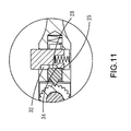
- a driving head 40 includes a driving member 41 such as an open end as show in Fig. 1 or a ratchet driving member as shown in Fig. 15 or a box end as shown in Fig. 16 .
- a second connection end 42 which is pivotably connected between the two protrusions 112 of the first connection end 11 by extending a pin "C" through the two respective first pin holes 113 on the two protrusions 112 and the second pin hole 44 defined through the insertion of the driving head 40.
- the insertion includes a second engagement end 43 which includes teeth defined therein.
- the teeth are shaped to include a V-shaped space or U-shaped space defined between the teeth of the second engagement end 43.
- a pawl 20 is movably received in the first hole 114 and biased by the spring "A", the pawl 20 includes a first engagement end 21 which is a wedge end and removably engaged with the teeth of the second engagement end 43.
- a first flat surface 22 is defined in a shank of the pawl 20 and a first contact surface 23 connects the at least one first flat surface 22.
- a first guide surface 25 connects the first contact surface 23 of the pawl 20.
- a button 30 is engaged with the second hole 115 and biased by the spring "B".
- the button 30 includes a second flat surface 31 which is matched with the first flat surface 22 of the pawl 20.
- a recess 32 is defined in the button 30 and located substantially perpendicular to the second flat surface 31.
- a second guide surface 34 is connected between the recess 32 and a second contact surface 33. As shown in Fig. 4 , the pawl 20 is pushed by the second contact surface 33 and the spring "B" so that the first engagement end 21 is engaged with the teeth of the second connection end 42 of the driving head 40.
- the button 30 when the button 30 is pushed by the user, the button 30 is lowered and the second contact surface 33 is disengaged from the first contact surface 23, the pawl 20 is then located in the recess 32 of the button 30.
- the pawl 20 is not longer positioned by the second contact surface 33 so that the driving head 40 can be pivoted and the second engagement end 43 of the driving head 40 moves over the first engagement end 21 of the pawl 20 to adjust the angle of the driving head 40 relative to the handle 10.
- the first engagement end 21 of the pawl 20 is engaged with the second engagement end 43 again and the pawl 20 is positioned by the button 30.
- Figs. 8-14 show another embodiment of the control device of the present invention, wherein the pawl 20 includes a slot 24 defined axially therein so as to define two first flat surfaces 22 in two facing insides of the slot 24.
- the button 30 includes two second flat surfaces 31 and the recess 32 is located at two respective ends of the two second flat surfaces 31.
- the shank of the button 30 is movably engaged with the slot 24 and the two second flat surfaces 31 are engaged with the first flat surfaces 22. By this way, the button 30 cannot rotate.
- the second contact surface 33 connects the recess 32 via the second guide surface 34 which is a curved and convex surface.
- the operation processes are the same as the first embodiment of the control device.
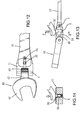
- Figs. 17 to 19 show that the first connection end 11 of the handle 10 includes an insertion and the second connection end 42 of the driving head 40 includes two protrusions with a space defined therebetween so that the insertion of the first connection end 11 of the handle 10 is pivotably connected between the two protrusions of the second connection end 42 by the pin "C".
- the pawl 20 is movably inserted in the first hole in the first connection end 11 and the button 30 is perpendicularly engaged with the pawl 20 in the first connection end 11.
- the pin "C” includes a second engagement end "C1" which includes teeth and located in the space between the two protrusions.
- the first engagement end 21 of the pawl 20 is engaged with the second engagement end "C1".
- the button 30 When the button 30 is pushed, the second contact surface 33 is disengaged from the first contact surface 23 of the pawl 20 and the pawl 20 is then located in the recess 32 of the button 30.
- the driving head 40 can be pivoted and the second engagement end C1 of the pin "C” moves over the first engagement end 21 of the pawl 20 to adjust the angle of the driving head 40 relative to the handle 10.
- the first engagement end 21 of the pawl 20 is engaged with the second engagement end "C1" again when releasing the button 30.
- the pawl 20 and the button 30 are directly in contact with each other and the pawl 20 is activated when the button 30 is pushed so that the number of parts can be minimized and the driving head 40 does not drop suddenly when the button 30 is pushed.
Landscapes
- Engineering & Computer Science (AREA)
- Mechanical Engineering (AREA)
- Portable Nailing Machines And Staplers (AREA)
- Finish Polishing, Edge Sharpening, And Grinding By Specific Grinding Devices (AREA)
- Details Of Spanners, Wrenches, And Screw Drivers And Accessories (AREA)
Applications Claiming Priority (1)
| Application Number | Priority Date | Filing Date | Title |
|---|---|---|---|
| CN200710163486A CN100591487C (zh) | 2007-10-26 | 2007-10-26 | 可弯曲角度的手工具 |
Publications (3)
| Publication Number | Publication Date |
|---|---|
| EP2052816A2 true EP2052816A2 (de) | 2009-04-29 |
| EP2052816A3 EP2052816A3 (de) | 2010-05-26 |
| EP2052816B1 EP2052816B1 (de) | 2013-12-11 |
Family
ID=39305510
Family Applications (1)
| Application Number | Title | Priority Date | Filing Date |
|---|---|---|---|
| EP08166276.9A Not-in-force EP2052816B1 (de) | 2007-10-26 | 2008-10-09 | Steuerungsvorrichtung für Handwerkzeug mit einstellbarem Winkel |
Country Status (2)
| Country | Link |
|---|---|
| EP (1) | EP2052816B1 (de) |
| CN (1) | CN100591487C (de) |
Cited By (1)
| Publication number | Priority date | Publication date | Assignee | Title |
|---|---|---|---|---|
| CN111163874A (zh) * | 2017-10-06 | 2020-05-15 | 米沃奇电动工具公司 | 齿轮传动的导管弯曲器 |
Families Citing this family (4)
| Publication number | Priority date | Publication date | Assignee | Title |
|---|---|---|---|---|
| CN105196233B (zh) * | 2015-11-13 | 2017-03-15 | 中国空气动力研究与发展中心低速空气动力研究所 | 一种定向软轴螺丝刀 |
| US20210187710A1 (en) * | 2017-12-07 | 2021-06-24 | Stanley Winnard | Hand-held tool with swivel joint adapter and fail-safe release mechanism |
| US12390911B2 (en) * | 2020-11-12 | 2025-08-19 | Snap-On Incorporated | Universal joint tool adapter assembly |
| TWI874986B (zh) * | 2023-05-05 | 2025-03-01 | 大陸商浙江邁特工具製造有限公司 | 扳手角度調整結構 |
Citations (2)
| Publication number | Priority date | Publication date | Assignee | Title |
|---|---|---|---|---|
| US7131356B2 (en) | 2004-06-02 | 2006-11-07 | Lea Way Hand Tool Corporation | Hand tool having an adjustable head with joint lock mechanism |
| US7168346B2 (en) | 2004-08-31 | 2007-01-30 | Lea Way Hand Tool Corporation | Hand tool having an adjustable head with a joint lock mechanism |
Family Cites Families (6)
| Publication number | Priority date | Publication date | Assignee | Title |
|---|---|---|---|---|
| CN2390726Y (zh) * | 1999-10-29 | 2000-08-09 | 胡厚飞 | 一种可小角度微调固定结构的棘轮扳手 |
| US6216317B1 (en) * | 1999-12-27 | 2001-04-17 | Tzn-Cha Chen | Handle adjustable in locating angle thereof |
| TWI242483B (en) * | 2002-10-25 | 2005-11-01 | Hou-Fei Hu | Fastener-driving tool assembly |
| TWI262118B (en) * | 2003-01-28 | 2006-09-21 | Hou-Fei Hu | Structure improvement of head-rotatable wrench |
| CN100478139C (zh) * | 2003-11-13 | 2009-04-15 | 香港商亚洲丹纳赫工具有限公司台湾分公司 | 具有定位锁定关节的手工具 |
| US6857341B1 (en) * | 2004-01-16 | 2005-02-22 | Chin Shun Cheng | F-type wrench structure |
-
2007
- 2007-10-26 CN CN200710163486A patent/CN100591487C/zh not_active Expired - Fee Related
-
2008
- 2008-10-09 EP EP08166276.9A patent/EP2052816B1/de not_active Not-in-force
Patent Citations (2)
| Publication number | Priority date | Publication date | Assignee | Title |
|---|---|---|---|---|
| US7131356B2 (en) | 2004-06-02 | 2006-11-07 | Lea Way Hand Tool Corporation | Hand tool having an adjustable head with joint lock mechanism |
| US7168346B2 (en) | 2004-08-31 | 2007-01-30 | Lea Way Hand Tool Corporation | Hand tool having an adjustable head with a joint lock mechanism |
Cited By (2)
| Publication number | Priority date | Publication date | Assignee | Title |
|---|---|---|---|---|
| CN111163874A (zh) * | 2017-10-06 | 2020-05-15 | 米沃奇电动工具公司 | 齿轮传动的导管弯曲器 |
| US11759838B2 (en) | 2017-10-06 | 2023-09-19 | Milwaukee Electric Tool Corporation | Geared conduit bender |
Also Published As
| Publication number | Publication date |
|---|---|
| CN101157215A (zh) | 2008-04-09 |
| EP2052816A3 (de) | 2010-05-26 |
| EP2052816B1 (de) | 2013-12-11 |
| CN100591487C (zh) | 2010-02-24 |
Similar Documents
| Publication | Publication Date | Title |
|---|---|---|
| US7581468B2 (en) | Control device for angle adjustable hand tool | |
| US7698972B2 (en) | Multi-angle tool handle | |
| US6976410B2 (en) | Tool bit drive adaptor | |
| EP2052816B1 (de) | Steuerungsvorrichtung für Handwerkzeug mit einstellbarem Winkel | |
| US6382052B1 (en) | Ratchet tool | |
| US7097084B2 (en) | Adjustable device for adjusting safety device of power nailers | |
| EP2058087B1 (de) | Schlüssel mit beweglichem Schieber für das metrische und das englische System | |
| US20090307847A1 (en) | Multi-function Tool | |
| US20080263777A1 (en) | Tool Frame Member Including Spring | |
| US7185565B1 (en) | Screwdriver having a ratchet mechanism | |
| US6895839B1 (en) | Control mechanism for controlling head of a box end wrench | |
| US6877751B2 (en) | Insertable tool connector | |
| US7353734B1 (en) | Screwdriver having a ratchet mechanism | |
| JP2014034099A (ja) | 綴じ具 | |
| US7641088B2 (en) | Nail gun with nail alignment adjustment device | |
| US7124664B1 (en) | Ratchet wrench | |
| US6516692B1 (en) | Pawl controlling device for ratchet tools | |
| US20040103766A1 (en) | Locking pliers | |
| EP2030735A2 (de) | Handwerkzeug mit austauschbarem Funktionskopf | |
| US20040089111A1 (en) | Ratchet tool having operation levers on two sides of the tool | |
| US5709145A (en) | Matrix plate holder and matrix plate for a hand stamp | |
| US6327941B1 (en) | Socket wrench extension structure | |
| US5926885A (en) | Combination chisel and punch | |
| US7472631B1 (en) | Hand tool with replaceable function head | |
| US7201085B1 (en) | Pivoting device for hand tools |
Legal Events
| Date | Code | Title | Description |
|---|---|---|---|
| PUAI | Public reference made under article 153(3) epc to a published international application that has entered the european phase |
Free format text: ORIGINAL CODE: 0009012 |
|
| AK | Designated contracting states |
Kind code of ref document: A2 Designated state(s): AT BE BG CH CY CZ DE DK EE ES FI FR GB GR HR HU IE IS IT LI LT LU LV MC MT NL NO PL PT RO SE SI SK TR |
|
| AX | Request for extension of the european patent |
Extension state: AL BA MK RS |
|
| PUAL | Search report despatched |
Free format text: ORIGINAL CODE: 0009013 |
|
| 17P | Request for examination filed |
Effective date: 20100330 |
|
| AK | Designated contracting states |
Kind code of ref document: A3 Designated state(s): AT BE BG CH CY CZ DE DK EE ES FI FR GB GR HR HU IE IS IT LI LT LU LV MC MT NL NO PL PT RO SE SI SK TR |
|
| AX | Request for extension of the european patent |
Extension state: AL BA MK RS |
|
| RIN1 | Information on inventor provided before grant (corrected) |
Inventor name: WU, ARTHUR |
|
| AKX | Designation fees paid |
Designated state(s): AT BE BG CH CY CZ DE DK EE ES FI FR GB GR HR HU IE IS IT LI LT LU LV MC MT NL NO PL PT RO SE SI SK TR |
|
| GRAP | Despatch of communication of intention to grant a patent |
Free format text: ORIGINAL CODE: EPIDOSNIGR1 |
|
| INTG | Intention to grant announced |
Effective date: 20130814 |
|
| GRAS | Grant fee paid |
Free format text: ORIGINAL CODE: EPIDOSNIGR3 |
|
| GRAA | (expected) grant |
Free format text: ORIGINAL CODE: 0009210 |
|
| AK | Designated contracting states |
Kind code of ref document: B1 Designated state(s): AT BE BG CH CY CZ DE DK EE ES FI FR GB GR HR HU IE IS IT LI LT LU LV MC MT NL NO PL PT RO SE SI SK TR |
|
| REG | Reference to a national code |
Ref country code: GB Ref legal event code: FG4D |
|
| REG | Reference to a national code |
Ref country code: CH Ref legal event code: EP |
|
| REG | Reference to a national code |
Ref country code: AT Ref legal event code: REF Ref document number: 644232 Country of ref document: AT Kind code of ref document: T Effective date: 20140115 |
|
| REG | Reference to a national code |
Ref country code: IE Ref legal event code: FG4D |
|
| REG | Reference to a national code |
Ref country code: DE Ref legal event code: R096 Ref document number: 602008029199 Country of ref document: DE Effective date: 20140206 |
|
| REG | Reference to a national code |
Ref country code: NL Ref legal event code: VDEP Effective date: 20131211 |
|
| REG | Reference to a national code |
Ref country code: AT Ref legal event code: MK05 Ref document number: 644232 Country of ref document: AT Kind code of ref document: T Effective date: 20131211 |
|
| PG25 | Lapsed in a contracting state [announced via postgrant information from national office to epo] |
Ref country code: NO Free format text: LAPSE BECAUSE OF FAILURE TO SUBMIT A TRANSLATION OF THE DESCRIPTION OR TO PAY THE FEE WITHIN THE PRESCRIBED TIME-LIMIT Effective date: 20140311 Ref country code: HR Free format text: LAPSE BECAUSE OF FAILURE TO SUBMIT A TRANSLATION OF THE DESCRIPTION OR TO PAY THE FEE WITHIN THE PRESCRIBED TIME-LIMIT Effective date: 20131211 Ref country code: LT Free format text: LAPSE BECAUSE OF FAILURE TO SUBMIT A TRANSLATION OF THE DESCRIPTION OR TO PAY THE FEE WITHIN THE PRESCRIBED TIME-LIMIT Effective date: 20131211 Ref country code: NL Free format text: LAPSE BECAUSE OF FAILURE TO SUBMIT A TRANSLATION OF THE DESCRIPTION OR TO PAY THE FEE WITHIN THE PRESCRIBED TIME-LIMIT Effective date: 20131211 Ref country code: FI Free format text: LAPSE BECAUSE OF FAILURE TO SUBMIT A TRANSLATION OF THE DESCRIPTION OR TO PAY THE FEE WITHIN THE PRESCRIBED TIME-LIMIT Effective date: 20131211 Ref country code: SE Free format text: LAPSE BECAUSE OF FAILURE TO SUBMIT A TRANSLATION OF THE DESCRIPTION OR TO PAY THE FEE WITHIN THE PRESCRIBED TIME-LIMIT Effective date: 20131211 |
|
| REG | Reference to a national code |
Ref country code: LT Ref legal event code: MG4D |
|
| PG25 | Lapsed in a contracting state [announced via postgrant information from national office to epo] |
Ref country code: LV Free format text: LAPSE BECAUSE OF FAILURE TO SUBMIT A TRANSLATION OF THE DESCRIPTION OR TO PAY THE FEE WITHIN THE PRESCRIBED TIME-LIMIT Effective date: 20131211 Ref country code: AT Free format text: LAPSE BECAUSE OF FAILURE TO SUBMIT A TRANSLATION OF THE DESCRIPTION OR TO PAY THE FEE WITHIN THE PRESCRIBED TIME-LIMIT Effective date: 20131211 Ref country code: CY Free format text: LAPSE BECAUSE OF FAILURE TO SUBMIT A TRANSLATION OF THE DESCRIPTION OR TO PAY THE FEE WITHIN THE PRESCRIBED TIME-LIMIT Effective date: 20131211 |
|
| PG25 | Lapsed in a contracting state [announced via postgrant information from national office to epo] |
Ref country code: EE Free format text: LAPSE BECAUSE OF FAILURE TO SUBMIT A TRANSLATION OF THE DESCRIPTION OR TO PAY THE FEE WITHIN THE PRESCRIBED TIME-LIMIT Effective date: 20131211 Ref country code: BE Free format text: LAPSE BECAUSE OF FAILURE TO SUBMIT A TRANSLATION OF THE DESCRIPTION OR TO PAY THE FEE WITHIN THE PRESCRIBED TIME-LIMIT Effective date: 20131211 Ref country code: IS Free format text: LAPSE BECAUSE OF FAILURE TO SUBMIT A TRANSLATION OF THE DESCRIPTION OR TO PAY THE FEE WITHIN THE PRESCRIBED TIME-LIMIT Effective date: 20140411 |
|
| PG25 | Lapsed in a contracting state [announced via postgrant information from national office to epo] |
Ref country code: CZ Free format text: LAPSE BECAUSE OF FAILURE TO SUBMIT A TRANSLATION OF THE DESCRIPTION OR TO PAY THE FEE WITHIN THE PRESCRIBED TIME-LIMIT Effective date: 20131211 Ref country code: SK Free format text: LAPSE BECAUSE OF FAILURE TO SUBMIT A TRANSLATION OF THE DESCRIPTION OR TO PAY THE FEE WITHIN THE PRESCRIBED TIME-LIMIT Effective date: 20131211 Ref country code: PL Free format text: LAPSE BECAUSE OF FAILURE TO SUBMIT A TRANSLATION OF THE DESCRIPTION OR TO PAY THE FEE WITHIN THE PRESCRIBED TIME-LIMIT Effective date: 20131211 Ref country code: ES Free format text: LAPSE BECAUSE OF FAILURE TO SUBMIT A TRANSLATION OF THE DESCRIPTION OR TO PAY THE FEE WITHIN THE PRESCRIBED TIME-LIMIT Effective date: 20131211 Ref country code: PT Free format text: LAPSE BECAUSE OF FAILURE TO SUBMIT A TRANSLATION OF THE DESCRIPTION OR TO PAY THE FEE WITHIN THE PRESCRIBED TIME-LIMIT Effective date: 20140411 Ref country code: RO Free format text: LAPSE BECAUSE OF FAILURE TO SUBMIT A TRANSLATION OF THE DESCRIPTION OR TO PAY THE FEE WITHIN THE PRESCRIBED TIME-LIMIT Effective date: 20131211 |
|
| REG | Reference to a national code |
Ref country code: DE Ref legal event code: R097 Ref document number: 602008029199 Country of ref document: DE |
|
| PLBE | No opposition filed within time limit |
Free format text: ORIGINAL CODE: 0009261 |
|
| STAA | Information on the status of an ep patent application or granted ep patent |
Free format text: STATUS: NO OPPOSITION FILED WITHIN TIME LIMIT |
|
| PG25 | Lapsed in a contracting state [announced via postgrant information from national office to epo] |
Ref country code: DK Free format text: LAPSE BECAUSE OF FAILURE TO SUBMIT A TRANSLATION OF THE DESCRIPTION OR TO PAY THE FEE WITHIN THE PRESCRIBED TIME-LIMIT Effective date: 20131211 |
|
| 26N | No opposition filed |
Effective date: 20140912 |
|
| REG | Reference to a national code |
Ref country code: DE Ref legal event code: R097 Ref document number: 602008029199 Country of ref document: DE Effective date: 20140912 |
|
| PG25 | Lapsed in a contracting state [announced via postgrant information from national office to epo] |
Ref country code: SI Free format text: LAPSE BECAUSE OF FAILURE TO SUBMIT A TRANSLATION OF THE DESCRIPTION OR TO PAY THE FEE WITHIN THE PRESCRIBED TIME-LIMIT Effective date: 20131211 |
|
| PG25 | Lapsed in a contracting state [announced via postgrant information from national office to epo] |
Ref country code: LU Free format text: LAPSE BECAUSE OF FAILURE TO SUBMIT A TRANSLATION OF THE DESCRIPTION OR TO PAY THE FEE WITHIN THE PRESCRIBED TIME-LIMIT Effective date: 20141009 Ref country code: MC Free format text: LAPSE BECAUSE OF FAILURE TO SUBMIT A TRANSLATION OF THE DESCRIPTION OR TO PAY THE FEE WITHIN THE PRESCRIBED TIME-LIMIT Effective date: 20131211 |
|
| REG | Reference to a national code |
Ref country code: CH Ref legal event code: PL |
|
| REG | Reference to a national code |
Ref country code: IE Ref legal event code: MM4A |
|
| PG25 | Lapsed in a contracting state [announced via postgrant information from national office to epo] |
Ref country code: CH Free format text: LAPSE BECAUSE OF NON-PAYMENT OF DUE FEES Effective date: 20141031 Ref country code: LI Free format text: LAPSE BECAUSE OF NON-PAYMENT OF DUE FEES Effective date: 20141031 |
|
| REG | Reference to a national code |
Ref country code: FR Ref legal event code: PLFP Year of fee payment: 8 |
|
| PG25 | Lapsed in a contracting state [announced via postgrant information from national office to epo] |
Ref country code: IE Free format text: LAPSE BECAUSE OF NON-PAYMENT OF DUE FEES Effective date: 20141009 |
|
| PG25 | Lapsed in a contracting state [announced via postgrant information from national office to epo] |
Ref country code: BG Free format text: LAPSE BECAUSE OF FAILURE TO SUBMIT A TRANSLATION OF THE DESCRIPTION OR TO PAY THE FEE WITHIN THE PRESCRIBED TIME-LIMIT Effective date: 20131211 |
|
| PG25 | Lapsed in a contracting state [announced via postgrant information from national office to epo] |
Ref country code: IT Free format text: LAPSE BECAUSE OF FAILURE TO SUBMIT A TRANSLATION OF THE DESCRIPTION OR TO PAY THE FEE WITHIN THE PRESCRIBED TIME-LIMIT Effective date: 20131211 Ref country code: GR Free format text: LAPSE BECAUSE OF FAILURE TO SUBMIT A TRANSLATION OF THE DESCRIPTION OR TO PAY THE FEE WITHIN THE PRESCRIBED TIME-LIMIT Effective date: 20140312 |
|
| PG25 | Lapsed in a contracting state [announced via postgrant information from national office to epo] |
Ref country code: HU Free format text: LAPSE BECAUSE OF FAILURE TO SUBMIT A TRANSLATION OF THE DESCRIPTION OR TO PAY THE FEE WITHIN THE PRESCRIBED TIME-LIMIT; INVALID AB INITIO Effective date: 20081009 Ref country code: MT Free format text: LAPSE BECAUSE OF FAILURE TO SUBMIT A TRANSLATION OF THE DESCRIPTION OR TO PAY THE FEE WITHIN THE PRESCRIBED TIME-LIMIT Effective date: 20131211 Ref country code: TR Free format text: LAPSE BECAUSE OF FAILURE TO SUBMIT A TRANSLATION OF THE DESCRIPTION OR TO PAY THE FEE WITHIN THE PRESCRIBED TIME-LIMIT Effective date: 20131211 |
|
| REG | Reference to a national code |
Ref country code: FR Ref legal event code: PLFP Year of fee payment: 9 |
|
| REG | Reference to a national code |
Ref country code: FR Ref legal event code: PLFP Year of fee payment: 10 |
|
| REG | Reference to a national code |
Ref country code: FR Ref legal event code: PLFP Year of fee payment: 11 |
|
| PGFP | Annual fee paid to national office [announced via postgrant information from national office to epo] |
Ref country code: DE Payment date: 20211028 Year of fee payment: 14 Ref country code: GB Payment date: 20211022 Year of fee payment: 14 |
|
| PGFP | Annual fee paid to national office [announced via postgrant information from national office to epo] |
Ref country code: FR Payment date: 20211022 Year of fee payment: 14 |
|
| REG | Reference to a national code |
Ref country code: DE Ref legal event code: R119 Ref document number: 602008029199 Country of ref document: DE |
|
| GBPC | Gb: european patent ceased through non-payment of renewal fee |
Effective date: 20221009 |
|
| PG25 | Lapsed in a contracting state [announced via postgrant information from national office to epo] |
Ref country code: FR Free format text: LAPSE BECAUSE OF NON-PAYMENT OF DUE FEES Effective date: 20221031 Ref country code: DE Free format text: LAPSE BECAUSE OF NON-PAYMENT OF DUE FEES Effective date: 20230503 |
|
| PG25 | Lapsed in a contracting state [announced via postgrant information from national office to epo] |
Ref country code: GB Free format text: LAPSE BECAUSE OF NON-PAYMENT OF DUE FEES Effective date: 20221009 |