EP2052782A1 - Dust collecting apparatus - Google Patents
Dust collecting apparatus Download PDFInfo
- Publication number
- EP2052782A1 EP2052782A1 EP07790751A EP07790751A EP2052782A1 EP 2052782 A1 EP2052782 A1 EP 2052782A1 EP 07790751 A EP07790751 A EP 07790751A EP 07790751 A EP07790751 A EP 07790751A EP 2052782 A1 EP2052782 A1 EP 2052782A1
- Authority
- EP
- European Patent Office
- Prior art keywords
- electrode
- dust collecting
- dust
- voltage
- charging
- Prior art date
- Legal status (The legal status is an assumption and is not a legal conclusion. Google has not performed a legal analysis and makes no representation as to the accuracy of the status listed.)
- Withdrawn
Links
Images


Classifications
-
- B—PERFORMING OPERATIONS; TRANSPORTING
- B03—SEPARATION OF SOLID MATERIALS USING LIQUIDS OR USING PNEUMATIC TABLES OR JIGS; MAGNETIC OR ELECTROSTATIC SEPARATION OF SOLID MATERIALS FROM SOLID MATERIALS OR FLUIDS; SEPARATION BY HIGH-VOLTAGE ELECTRIC FIELDS
- B03C—MAGNETIC OR ELECTROSTATIC SEPARATION OF SOLID MATERIALS FROM SOLID MATERIALS OR FLUIDS; SEPARATION BY HIGH-VOLTAGE ELECTRIC FIELDS
- B03C3/00—Separating dispersed particles from gases or vapour, e.g. air, by electrostatic effect
- B03C3/02—Plant or installations having external electricity supply
- B03C3/04—Plant or installations having external electricity supply dry type
- B03C3/08—Plant or installations having external electricity supply dry type characterised by presence of stationary flat electrodes arranged with their flat surfaces parallel to the gas stream
-
- B—PERFORMING OPERATIONS; TRANSPORTING
- B03—SEPARATION OF SOLID MATERIALS USING LIQUIDS OR USING PNEUMATIC TABLES OR JIGS; MAGNETIC OR ELECTROSTATIC SEPARATION OF SOLID MATERIALS FROM SOLID MATERIALS OR FLUIDS; SEPARATION BY HIGH-VOLTAGE ELECTRIC FIELDS
- B03C—MAGNETIC OR ELECTROSTATIC SEPARATION OF SOLID MATERIALS FROM SOLID MATERIALS OR FLUIDS; SEPARATION BY HIGH-VOLTAGE ELECTRIC FIELDS
- B03C3/00—Separating dispersed particles from gases or vapour, e.g. air, by electrostatic effect
- B03C3/34—Constructional details or accessories or operation thereof
- B03C3/40—Electrode constructions
- B03C3/41—Ionising-electrodes
-
- B—PERFORMING OPERATIONS; TRANSPORTING
- B03—SEPARATION OF SOLID MATERIALS USING LIQUIDS OR USING PNEUMATIC TABLES OR JIGS; MAGNETIC OR ELECTROSTATIC SEPARATION OF SOLID MATERIALS FROM SOLID MATERIALS OR FLUIDS; SEPARATION BY HIGH-VOLTAGE ELECTRIC FIELDS
- B03C—MAGNETIC OR ELECTROSTATIC SEPARATION OF SOLID MATERIALS FROM SOLID MATERIALS OR FLUIDS; SEPARATION BY HIGH-VOLTAGE ELECTRIC FIELDS
- B03C3/00—Separating dispersed particles from gases or vapour, e.g. air, by electrostatic effect
- B03C3/34—Constructional details or accessories or operation thereof
- B03C3/40—Electrode constructions
- B03C3/45—Collecting-electrodes
- B03C3/47—Collecting-electrodes flat, e.g. plates, discs, gratings
-
- B—PERFORMING OPERATIONS; TRANSPORTING
- B03—SEPARATION OF SOLID MATERIALS USING LIQUIDS OR USING PNEUMATIC TABLES OR JIGS; MAGNETIC OR ELECTROSTATIC SEPARATION OF SOLID MATERIALS FROM SOLID MATERIALS OR FLUIDS; SEPARATION BY HIGH-VOLTAGE ELECTRIC FIELDS
- B03C—MAGNETIC OR ELECTROSTATIC SEPARATION OF SOLID MATERIALS FROM SOLID MATERIALS OR FLUIDS; SEPARATION BY HIGH-VOLTAGE ELECTRIC FIELDS
- B03C2201/00—Details of magnetic or electrostatic separation
- B03C2201/06—Ionising electrode being a needle
Definitions
- This invention relates to dust collectors for collecting dust electrically charged in the air.
- Electric dust collectors of electrostatic type are conventionally known that include an air passage, a charging part placed in the air passage and a dust collecting part placed downstream of the charging part (see Patent Document 1).
- the electric dust collectors are configured to collect by adsorption dust in the air introduced into the air passage, thereby cleaning the air containing the dust.
- the charging part of the electric dust collector positively charges the dust having flowed into the air passage.
- the dust collecting part collects by adsorption the dust positively charged by the charging part.
- the dust is separated from the air containing it to clean the air.
- the dust collecting part in Patent Document 1 includes dust collecting electrodes formed in the shape of a flat plate and high-voltage electrodes of the same shape, wherein the dust collecting electrodes and the high-voltage electrodes are alternately arranged in parallel.
- the dust collecting electrodes are grounded, while the high-voltage electrodes are connected to the positive side of a power supply provided in the electric dust collector.
- a voltage is applied from the power supply, whereby a predetermined potential difference is created between each pair of adjacent high-voltage and dust collecting electrodes. Positively charged dust flows into the spaces where the predetermined potential difference is created, and is collected by adsorption on the grounded dust collecting electrodes.
- Patent Document 1 Published Japanese Patent Application No. H01-310753
- the resistance between each pair of adjacent dust collecting and high-voltage electrodes may drop to allow an excessive electric current to flow between the adjacent electrodes and thereby cause a spark (spark discharge). Furthermore, also when electroconductive powder dust is mixed in positively charged dust flowing into the dust collecting part, an excessive electric current may flow between the adjacent electrodes and thereby cause a spark. In short, when under normal operating conditions the resistance between the adjacent electrodes drops owing to some influence, a spark is caused between the electrodes.
- the present invention has been made in view of the foregoing points and, therefore, an object thereof is to prevent the occurrence of spark between each adjacent electrodes in the dust collecting part while reducing deterioration in the dust collecting capacity of the dust collecting part.
- a first aspect of the present invention is directed to a dust collector including: a charging part (12) for charging dust in the air with electricity; a dust collecting part (30) including a first electrode (40) and a second electrode (50) disposed near the first electrode (40); and a power supply for applying a voltage to the dust collecting part (30).
- the charging part (12) of the dust collector includes a charging means (12a) for positively charging the dust.
- the first electrode (40) is grounded and the second electrode (50) is connected to the positive side of the power supply.
- the first electrode (40) is made of an electroconductive resin.
- the first electrode (40) is constituted as a dust collecting electrode (40) for collecting the charged dust by adsorption.
- the grounded first electrode (dust collecting electrode) (40) is made of an electroconductive resin, the volume resistivity of the dust collecting electrode (40) can be increased as compared to, for example, electrodes made of metal.
- a second aspect of the invention is the dust collector according to the first aspect of the invention, wherein the volume resistivity of the electroconductive resin is 10 8 ⁇ cm to 10 12 ⁇ cm, both inclusive.
- the volume resistivity of the electroconductive resin since the volume resistivity of the electroconductive resin is specified, a predetermined volume resistivity can be given to the dust collecting electrode (40) constituting the first electrode.
- the volume resistivity of the electroconductive resin if the volume resistivity of the electroconductive resin is too low, the electroconductive resin loses resin characteristics, thereby easily causing a spark.
- the volume resistivity of the electroconductive resin is too high, the mobility of charges within the dust collecting electrode (40) upon approach of dust is decreased. Therefore, the mobility of charges to the surface of the dust collecting electrode (40) is decreased, resulting in a significantly deteriorated dust collecting capacity of the dust collecting part (30).
- the dust collecting electrode (40) can be constituted as an electrode that reduces deterioration in the dust collecting capacity of the dust collecting part (30) while maintaining its resin characteristics.
- a third aspect of the invention is the dust collector according to the first or second aspect of the invention, wherein the second electrode (50) connected to the positive side of the power supply is made of an electroconductive resin and the volume resistivity of the electroconductive resin is 10 3 ⁇ cm to 10 8 ⁇ cm, both inclusive.
- a predetermined volume resistivity is given not only to the dust collecting electrode (40) but also to the second electrode (high-voltage electrode) (50) connected to the positive side of the power supply.
- respective suitable volume resistivities for the dust collecting electrode (40) and the high-voltage electrode (50) can be set within the ranges of volume resistivities of respective electroconductive resins for the electrodes (40, 50).
- a fourth aspect of the present invention is directed to a dust collector including: a charging part (12) for charging dust in the air with electricity; a dust collecting part (30) including a first electrode (40) and a second electrode (50) disposed near the first electrode (40); and a power supply for applying a voltage to the dust collecting part (30).
- the charging part (12) of the dust collector includes a charging means (12a) for negatively charging the dust.
- the first electrode (40) is grounded and the second electrode (50) is connected to the negative side of the power supply.
- the first electrode (40) is made of an electroconductive resin.
- the grounded first electrode (dust collecting electrode) (40) is made of an electroconductive resin, the volume resistivity of the dust collecting electrode (40) can be increased as compared to, for example, electrodes made of metal.
- a fifth aspect of the invention is the dust collector according to the fourth aspect of the invention, wherein the volume resistivity of the electroconductive resin is 10 8 ⁇ cm to 10 12 ⁇ cm, both inclusive.
- the volume resistivity of the electroconductive resin is specified, a predetermined volume resistivity can be given to the dust collecting electrode (40).
- a sixth aspect of the invention is the dust collector according to the fourth or fifth aspect of the invention, wherein the second electrode (50) connected to the negative side of the power supply is made of an electroconductive resin and the volume resistivity of the electroconductive resin is 10 3 ⁇ cm to 10 8 ⁇ cm, both inclusive.
- a predetermined volume resistivity is given not only to the dust collecting electrode (40) but also to the second electrode (high-voltage electrode) (50) connected to the negative side of the power supply.
- respective suitable volume resistivities for the dust collecting electrode (40) and the high-voltage electrode (50) can be set within the ranges of volume resistivities of respective electroconductive resins for the electrodes (40, 50).
- the volume resistivity of the dust collecting electrode (40) can be increased by making the first electrode (40) from an electroconductive resin. Therefore, even if the resistance between the first electrode (40) and the second electrode (50) drops owing to some influence, it can be prevented that an excessive current flows between the electrodes. Thus, the occurrence of spark can be prevented without reducing the voltage applied from the power supply below a predetermined value or increasing the distance between the electrodes above a predetermined value.
- the occurrence of spark can be prevented while deterioration in the dust collecting capacity of the dust collecting part (30) can be reduced.
- the electrodes (40, 50) in giving volume resistivities to the electrodes (40, 50) of the dust collecting part (30), the electrodes (40, 50) can be independently given their respective volume resistivities. Therefore, the occurrence of spark can be prevented while the flexibility of configuration of the electrodes (40, 50) can be increased.
- the volume resistivity of the first electrode (40) can be increased by making the first electrode (40) from an electroconductive resin. Therefore, even if the resistance between the first electrode (40) and the second electrode (50) drops owing to some influence, it can be prevented that an excessive current flows between the electrodes (40, 50).
- the occurrence of spark can be prevented while the deterioration in the dust collecting capacity of the dust collecting part (30) can be reduced.
- the electrodes (40, 50) in giving volume resistivities to the electrodes (40, 50) of the dust collecting part (30), the electrodes (40, 50) can be independently given their respective volume resistivities. Therefore, the occurrence of spark can be prevented while the flexibility of configuration of the electrodes (40, 50) can be increased.
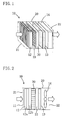
- FIG. 1 is a schematic perspective view showing the general structure of an air cleaner according to an embodiment of the present invention.
- FIG. 2 is a schematic side view showing the general structure of the air cleaner according to the above embodiment of the present invention.
- FIG. 3 is a perspective view showing a dust collecting part in the above embodiment of the present invention.
- FIG. 4 is a perspective view showing part of the dust collecting part in the above embodiment of the present invention in magnified form.
- FIG. 5 is a cross-sectional side view showing part of the dust collecting part in the above embodiment of the present invention in magnified form.
- FIG. 6 is a schematic perspective view of a dust collecting part in another embodiment of the present invention.
- FIG. 7 is a schematic perspective view of a dust collecting part in still another embodiment of the present invention.
- an air cleaner (10) constitutes a dust collector according to the present invention and is, for example, a household air cleaner used at home or in a small store.
- the air cleaner (10) includes a casing (20) and also includes a prefilter (11), a charging part (12), a dust collecting part (30), a catalyst filter (13) and a fan (14) that are contained in the casing (20).
- the air cleaner (10) includes a power supply, which is not shown here, for applying voltage to the charging part (12) and the dust collecting part (30).
- the casing (20) is formed, for example, in a rectangular, horizontally long container. Its front surface forms an air inlet (21), its back surface forms an air outlet (22) and its interior forms an air passage (23).
- the prefilter (11), the charging part (12), the dust collecting part (30), the catalyst filter (13) and the fan (14) are arranged in this order from the inlet (21) towards the outlet (22).
- the prefilter (11) constitutes a filter for collecting relatively large dust in the air taken through the inlet (21) into the casing (20).
- the charging part (12) constitutes an ionizer to charge relatively small dust having passed through the prefilter (11) with electricity.
- the charging part (12) is composed, for example, of a plurality of ionizing wires (a charging means) (12a) and a plurality of opposed electrodes (12b) opposed to the ionizing wires (12a).
- the ionizing wires (12a) are connected to the positive side of the power supply, while the opposed electrodes (12b) are connected to the negative side of the power supply.
- the charging part (12) is configured so that a direct-current voltage can be applied between the ionizing wires (12a) and the opposed electrodes (12b).
- the ionizing wires (12a) are disposed to extend from the upper end to lower end of the charging part (12), and the opposed electrodes(12b) are disposed, one between adjacent two of the ionizing wires (12a).
- the dust collecting part (30) is configured to collect dust electrically charged at the charging part (12) by adsorption and includes, as shown in FIGS. 3 to 5 , a dust collecting electrode (40) as a first electrode and a high-voltage electrode (50) as a second electrode.
- the dust collecting electrode (40) is grounded, while the high-voltage electrode (50) is connected to the positive side of the power supply.
- the dust collecting electrode (40) and the high-voltage electrode (50) constitute paired electrodes opposed to each other.
- Each of the dust collecting electrode (40) and the high-voltage electrode (50) of the dust collecting part (30) is formed by integral molding.
- the dust collecting electrode (40) and the high-voltage electrode (50) are formed in substantially the same shape and configured in an insertion structure in which they can be partly inserted into each other.
- Each of the dust collecting electrode (40) and the high-voltage electrode (50) is formed in a rectangular shape and includes a single base (41, 51) and a large number of projections (42, 52) projecting from the base (41, 51).
- the base (41, 51) includes a frame (43, 53), a plurality of vertical partitions (44, 54) arranged within the frame (43, 53) and a plurality of horizontal partitions (45, 55) arranged within the frame (43, 53).
- the frame (43, 53) is formed in a rectangular shape.
- the frame (43) of the dust collecting electrode (40) is formed with a larger thickness than the frame (53) of the high-voltage electrode (50).
- the frame (43) of the dust collecting electrode (40) has thickness-reduced portions (4a) formed at its four corners, and the thickness-reduced portions (4a) have their respective fixing legs (4c) formed thereon and having fixing holes (4b).
- the frame (53) of the high-voltage electrode (50) has thickness-reduced portions (5a) formed at its four corners, and the thickness-reduced portions (5a) have fixing holes (5b) formed therein.
- the frame (43) of the dust collecting electrode (40) and the frame (53) of the high-voltage electrode (50) are fixed to each other at their four corners (4a, 5a) through the fixing legs (4c) by screwing tapping screws through the fixing holes (5b) into the respective associated fixing holes (4b), whereby the base (41) of the dust collecting electrode (40) and the base (51) of the high-voltage electrode (50) are disposed to face each other. Furthermore, the bases (41, 51) of the dust collecting electrode (40) and the high-voltage electrode (50) are oriented in a direction orthogonal to the air flow in the air passage (23).
- the vertical partitions (44, 54) of the dust collecting electrode (40) and the high-voltage electrode (50) extend in the vertical direction of the casing (20), while the horizontal partitions (45, 55) thereof extend in the horizontal direction of the casing (20).
- the vertical partitions (44, 54) and the horizontal partitions (45, 55) are arranged to crisscross each other.
- Each base (41, 51) has a large number of vent holes (46, 56) formed therein and surrounded by the frame (43, 53), the vertical partitions (44, 54) and the horizontal partitions (45, 55).
- the base (41, 51) is formed in a rectangular grid structure by the vertical partitions (44, 54) and the horizontal partitions (45, 55), thereby forming a large number of rectangular tubular parts to form the vent holes (46, 56).
- Each of the vertical partitions (44) of the dust collecting electrode (40) and an associated one of the vertical partitions (54) of the high-voltage electrode (50) are formed to be in the same plane in an assembled state where the base (41) of the dust collecting electrode (40) and the base (51) of the high-voltage electrode (50) are locked with each other.
- the horizontal partitions (45) of the dust collecting electrode (40) and the horizontal partitions (55) of the high-voltage electrode (50) are formed to be alternately arranged in a vertically staggered pattern in FIG. 5 in the assembled state where the base (41) of the dust collecting electrode (40) and the base (51) of the high-voltage electrode (50) are locked with each other.
- the horizontal partitions (45) of the dust collecting electrode (40) are located in the middle of the vent holes (56) of the high-voltage electrode (50), while the horizontal partitions (55) of the high-voltage electrode (50) are located in the middle of the vent holes (46) of the dust collecting electrode (40).
- the projections (42, 52) are integrally formed with the associated horizontal partitions (45, 55) to project from them.
- the projections (42, 52) are formed into projecting pieces in the shape of a flat plate having the same thickness as the horizontal partitions (45, 55) and extend towards the inside of the associated vent holes (56, 46) of the opposed electrodes (50, 40). Furthermore, the projections (42, 52) are formed so that each of the vertical partitions (54, 44) of the opposed electrode (50, 40) is located in a clearance between horizontally adjacent two of the projections (42, 52).
- the projections (42, 52) are each located in the middle of the associated vent hole (56, 46) in the assembled state where the base (41) of the dust collecting electrode (40) and the base (51) of the high-voltage electrode (50) are locked with each other, whereby air flows above and below the projections (42, 52).
- Each projection (42) of the dust collecting electrode (40) and the adjacent projection (52) of the high-voltage electrode (50) are configured to have a distance of 1.8mm to 2.0mm between them.
- the vertical partitions (44) of the dust collecting electrode (40) and the vertical partitions (54) of the high-voltage electrode (50) are located a predetermined distance apart from and without contact with each other in the assembled state where the base (41) of the dust collecting electrode (40) and the base (51) of the high-voltage electrode (50) are locked with each other.
- a direct-current voltage is applied between the dust collecting electrode (40) and the high-voltage electrode (50) to create an electric field between them, whereby electrically charged dust is adsorbed on the dust collecting electrode (40).
- each of the dust collecting electrode (40) and the high-voltage electrode (50) of the dust collecting part (30) is made of an electroconductive resin.
- the volume resistivity of the dust collecting electrode (40) is preferably 10 8 ⁇ cm to 10 12 ⁇ cm, both inclusive
- the volume resistivity of the high-voltage electrode (50) is preferably 10 3 ⁇ cm to 10 8 ⁇ cm, both inclusive.
- the catalyst filter (13) is formed, for example, by carrying a catalyst on the surface of a support material having a honeycomb structure.
- Applicable catalysts include manganese catalysts and precious metal catalysts. The catalyst decomposes toxic substances and odorous substances in the air from which dust has been removed by the passage through the dust collecting part (30).
- the fan (14) is disposed at the most downstream site of the air passage (23) in the casing (20) and configured to draw room air into the casing (20) and then blow clean air to the room.
- a direct-current voltage is applied between each ionizing wire (12a) and the associated opposed electrode (12b) in the charging part (12) and a direct-current voltage is also applied between the dust collecting electrode (40) and the high-voltage electrode (50) of the dust collecting part (30).
- the prefilter (11) collects relatively large dust in the room air first.
- the room air having passed through the prefilter (11) flows into the charging part (12).
- relatively small dust having passed through the prefilter (11) is charged with electricity to take a positive charge, for example, and the electrically charged dust flows downstream.
- the electrically charged dust flows into the dust collecting part (30) and flows through the vent holes (46, 56) in the bases (41, 51) of the dust collecting electrode (40) and the high-voltage electrode (50).
- the room air flows through the vent holes (46, 56) formed by the frames (43, 53), the vertical partitions (44, 54) and the horizontal partitions (45, 55) of the bases (41, 51) of the dust collecting electrode (40) and the high-voltage electrode (50) and flows around each of the projections (42, 52) of the dust collecting electrode (40) and the high-voltage electrode (50).
- the dust collecting electrode (40) serves as an earth electrode, for example, the dust charged with positive electricity is adsorbed on the dust collecting electrode (40) by an electrical image force. Specifically, the dust is adsorbed on the inner surface of the frame (43) of the dust collecting electrode (40), the surfaces of the vertical partitions (44) thereof, the surfaces of the horizontal partitions (45) thereof and the surfaces of the projections (42) thereof.
- the room air from which the dust has been removed flows through the catalyst filter (13), whereby toxic substances and odorous substances in the air are decomposed and clean air is thereby produced.
- the clean air passes through the fan (14) and is then blown through the air passage (23) to the room. The above operation is repeated to clean room air.
- the volume resistivity of the dust collecting electrode (40) can be increased by making the dust collecting electrode (40) from an electroconductive resin. Therefore, even if the resistance between the dust collecting electrode (40) and the high-voltage electrode (50) drops owing to some influence, it can be prevented that an excessive current flows between the electrodes. Specifically, even if dust adheres to the surface of the dust collecting electrode (40) of the dust collecting part (30) over and over and is deposited thereon or if electroconductive powder dust is mixed in positively charged dust flowing into the dust collecting part (30), it can be prevented that an excessive current flows between the electrodes. As a result, the occurrence of spark can be prevented.
- the volume resistivity of the dust collecting electrode (40) is 10 8 ⁇ cm to 10 12 ⁇ cm, both inclusive
- the volume resistivity of the high-voltage electrode (50) is 10 3 ⁇ cm to 10 8 ⁇ cm, both inclusive
- the above embodiment of the present invention may have the following configurations.
- a dust collecting part (30) may be constituted so that a plurality of board-shaped dust collecting electrodes (40) and a plurality of board-shaped high-voltage electrodes (50) are alternately arranged in parallel.
- a dust collecting part (30) may be constituted by a combination of a plurality of high-voltage electrodes (50) of slender square column form and a grid dust collecting electrode (40).
- the air cleaner may be configured by connecting the ionizing wires (12a) of the charging part (12) to the negative side of the power supply, connecting the opposed electrodes (12b) of the charging part (12) to the positive side of the power supply and connecting the high-voltage electrode (40) of the dust collecting part (30) to the negative side of the power supply.
- each of the dust collecting electrode (40) and the high-voltage electrode (50) can be made from an electroconductive resin.
- the dust collector of the present invention is not limited to application to an air cleaner (10), may be assembled in an air conditioner or may include no catalyst part (13).
- the present invention is useful for dust collectors for collecting dust electrically charged in the air.
Landscapes
- Electrostatic Separation (AREA)
Abstract
Description
- This invention relates to dust collectors for collecting dust electrically charged in the air.
- Electric dust collectors of electrostatic type are conventionally known that include an air passage, a charging part placed in the air passage and a dust collecting part placed downstream of the charging part (see Patent Document 1). The electric dust collectors are configured to collect by adsorption dust in the air introduced into the air passage, thereby cleaning the air containing the dust. Specifically, first, the charging part of the electric dust collector positively charges the dust having flowed into the air passage. Next, the dust collecting part collects by adsorption the dust positively charged by the charging part. Thus, the dust is separated from the air containing it to clean the air.
- The dust collecting part in Patent Document 1 includes dust collecting electrodes formed in the shape of a flat plate and high-voltage electrodes of the same shape, wherein the dust collecting electrodes and the high-voltage electrodes are alternately arranged in parallel. The dust collecting electrodes are grounded, while the high-voltage electrodes are connected to the positive side of a power supply provided in the electric dust collector. A voltage is applied from the power supply, whereby a predetermined potential difference is created between each pair of adjacent high-voltage and dust collecting electrodes. Positively charged dust flows into the spaces where the predetermined potential difference is created, and is collected by adsorption on the grounded dust collecting electrodes. Patent Document 1: Published Japanese Patent Application No.
H01-310753 - When during operation of the electric dust collector dust adheres to the surfaces of the dust collecting electrodes of the dust collecting part over and over in the above manner and is deposited thereon, the resistance between each pair of adjacent dust collecting and high-voltage electrodes may drop to allow an excessive electric current to flow between the adjacent electrodes and thereby cause a spark (spark discharge). Furthermore, also when electroconductive powder dust is mixed in positively charged dust flowing into the dust collecting part, an excessive electric current may flow between the adjacent electrodes and thereby cause a spark. In short, when under normal operating conditions the resistance between the adjacent electrodes drops owing to some influence, a spark is caused between the electrodes. To prevent the occurrence of spark, it is conceivable to reduce the voltage applied from the power supply below a predetermined value or to increase the distance between each adjacent electrodes above a predetermined value. These measures can prevent the occurrence of spark but the dust collecting capacity of the dust collecting part is significantly deteriorated as compared to a desired capacity.
- The present invention has been made in view of the foregoing points and, therefore, an object thereof is to prevent the occurrence of spark between each adjacent electrodes in the dust collecting part while reducing deterioration in the dust collecting capacity of the dust collecting part.
- A first aspect of the present invention is directed to a dust collector including: a charging part (12) for charging dust in the air with electricity; a dust collecting part (30) including a first electrode (40) and a second electrode (50) disposed near the first electrode (40); and a power supply for applying a voltage to the dust collecting part (30).
- Furthermore, the charging part (12) of the dust collector includes a charging means (12a) for positively charging the dust. The first electrode (40) is grounded and the second electrode (50) is connected to the positive side of the power supply. In addition, the first electrode (40) is made of an electroconductive resin. In this case, the first electrode (40) is constituted as a dust collecting electrode (40) for collecting the charged dust by adsorption.
- In the first aspect of the invention, since the grounded first electrode (dust collecting electrode) (40) is made of an electroconductive resin, the volume resistivity of the dust collecting electrode (40) can be increased as compared to, for example, electrodes made of metal.
- A second aspect of the invention is the dust collector according to the first aspect of the invention, wherein the volume resistivity of the electroconductive resin is 108 Ωcm to 1012 Ωcm, both inclusive.
- In the second aspect of the invention, since the volume resistivity of the electroconductive resin is specified, a predetermined volume resistivity can be given to the dust collecting electrode (40) constituting the first electrode. In this relation, if the volume resistivity of the electroconductive resin is too low, the electroconductive resin loses resin characteristics, thereby easily causing a spark. On the contrary, if the volume resistivity of the electroconductive resin is too high, the mobility of charges within the dust collecting electrode (40) upon approach of dust is decreased. Therefore, the mobility of charges to the surface of the dust collecting electrode (40) is decreased, resulting in a significantly deteriorated dust collecting capacity of the dust collecting part (30). If the volume resistivity of the electroconductive resin is specified in the manner of the second aspect of the invention, the dust collecting electrode (40) can be constituted as an electrode that reduces deterioration in the dust collecting capacity of the dust collecting part (30) while maintaining its resin characteristics.
- A third aspect of the invention is the dust collector according to the first or second aspect of the invention, wherein the second electrode (50) connected to the positive side of the power supply is made of an electroconductive resin and the volume resistivity of the electroconductive resin is 103 Ωcm to 108 Ωcm, both inclusive.
- In the third aspect of the invention, a predetermined volume resistivity is given not only to the dust collecting electrode (40) but also to the second electrode (high-voltage electrode) (50) connected to the positive side of the power supply. As a result, respective suitable volume resistivities for the dust collecting electrode (40) and the high-voltage electrode (50) can be set within the ranges of volume resistivities of respective electroconductive resins for the electrodes (40, 50).
- A fourth aspect of the present invention is directed to a dust collector including: a charging part (12) for charging dust in the air with electricity; a dust collecting part (30) including a first electrode (40) and a second electrode (50) disposed near the first electrode (40); and a power supply for applying a voltage to the dust collecting part (30).
- Furthermore, the charging part (12) of the dust collector includes a charging means (12a) for negatively charging the dust. The first electrode (40) is grounded and the second electrode (50) is connected to the negative side of the power supply. In addition, the first electrode (40) is made of an electroconductive resin.
- In the fourth aspect of the invention, like the first aspect of the invention, since the grounded first electrode (dust collecting electrode) (40) is made of an electroconductive resin, the volume resistivity of the dust collecting electrode (40) can be increased as compared to, for example, electrodes made of metal.
- A fifth aspect of the invention is the dust collector according to the fourth aspect of the invention, wherein the volume resistivity of the electroconductive resin is 108 Ωcm to 1012 Ωcm, both inclusive.
- In the fifth aspect of the invention, like the second aspect of the invention, since the volume resistivity of the electroconductive resin is specified, a predetermined volume resistivity can be given to the dust collecting electrode (40).
- A sixth aspect of the invention is the dust collector according to the fourth or fifth aspect of the invention, wherein the second electrode (50) connected to the negative side of the power supply is made of an electroconductive resin and the volume resistivity of the electroconductive resin is 103 Ωcm to 108 Ωcm, both inclusive.
- In the sixth aspect of the invention, like the third aspect of the invention, a predetermined volume resistivity is given not only to the dust collecting electrode (40) but also to the second electrode (high-voltage electrode) (50) connected to the negative side of the power supply. As a result, respective suitable volume resistivities for the dust collecting electrode (40) and the high-voltage electrode (50) can be set within the ranges of volume resistivities of respective electroconductive resins for the electrodes (40, 50).
- According to the first aspect of the invention, the volume resistivity of the dust collecting electrode (40) can be increased by making the first electrode (40) from an electroconductive resin. Therefore, even if the resistance between the first electrode (40) and the second electrode (50) drops owing to some influence, it can be prevented that an excessive current flows between the electrodes. Thus, the occurrence of spark can be prevented without reducing the voltage applied from the power supply below a predetermined value or increasing the distance between the electrodes above a predetermined value.
- According to the second aspect of the invention, with the use of the electroconductive resin having a predetermined volume resistivity, the occurrence of spark can be prevented while deterioration in the dust collecting capacity of the dust collecting part (30) can be reduced.
- According to the third aspect of the invention, in giving volume resistivities to the electrodes (40, 50) of the dust collecting part (30), the electrodes (40, 50) can be independently given their respective volume resistivities. Therefore, the occurrence of spark can be prevented while the flexibility of configuration of the electrodes (40, 50) can be increased.
- According to the fourth aspect of the invention, like the first aspect of the invention, the volume resistivity of the first electrode (40) can be increased by making the first electrode (40) from an electroconductive resin. Therefore, even if the resistance between the first electrode (40) and the second electrode (50) drops owing to some influence, it can be prevented that an excessive current flows between the electrodes (40, 50).
- According to the fifth aspect of the invention, like the second aspect of the invention, with the use of the electroconductive resin having a predetermined volume resistivity, the occurrence of spark can be prevented while the deterioration in the dust collecting capacity of the dust collecting part (30) can be reduced.
- According to the sixth aspect of the invention, like the third aspect of the invention, in giving volume resistivities to the electrodes (40, 50) of the dust collecting part (30), the electrodes (40, 50) can be independently given their respective volume resistivities. Therefore, the occurrence of spark can be prevented while the flexibility of configuration of the electrodes (40, 50) can be increased.
- [
FIG. 1] FIG. 1 is a schematic perspective view showing the general structure of an air cleaner according to an embodiment of the present invention. - [
FIG. 2] FIG. 2 is a schematic side view showing the general structure of the air cleaner according to the above embodiment of the present invention. - [
FIG. 3] FIG. 3 is a perspective view showing a dust collecting part in the above embodiment of the present invention. - [
FIG. 4] FIG. 4 is a perspective view showing part of the dust collecting part in the above embodiment of the present invention in magnified form. - [
FIG. 5] FIG. 5 is a cross-sectional side view showing part of the dust collecting part in the above embodiment of the present invention in magnified form. - [
FIG. 6] FIG. 6 is a schematic perspective view of a dust collecting part in another embodiment of the present invention. - [
FIG. 7] FIG. 7 is a schematic perspective view of a dust collecting part in still another embodiment of the present invention. -
- 10
- air cleaner (dust collector)
- 12
- charging part
- 30
- dust collecting part
- 40
- dust collecting electrode (first electrode)
- 50
- high-voltage electrode (second electrode)
- Embodiments of the present invention will be described below in detail with reference to the drawings.
- As shown in
FIGS. 1 and 2 , an air cleaner (10) according to this embodiment constitutes a dust collector according to the present invention and is, for example, a household air cleaner used at home or in a small store. - The air cleaner (10) includes a casing (20) and also includes a prefilter (11), a charging part (12), a dust collecting part (30), a catalyst filter (13) and a fan (14) that are contained in the casing (20). The air cleaner (10) includes a power supply, which is not shown here, for applying voltage to the charging part (12) and the dust collecting part (30).
- The casing (20) is formed, for example, in a rectangular, horizontally long container. Its front surface forms an air inlet (21), its back surface forms an air outlet (22) and its interior forms an air passage (23). The prefilter (11), the charging part (12), the dust collecting part (30), the catalyst filter (13) and the fan (14) are arranged in this order from the inlet (21) towards the outlet (22).
- The prefilter (11) constitutes a filter for collecting relatively large dust in the air taken through the inlet (21) into the casing (20).
- The charging part (12) constitutes an ionizer to charge relatively small dust having passed through the prefilter (11) with electricity. The charging part (12) is composed, for example, of a plurality of ionizing wires (a charging means) (12a) and a plurality of opposed electrodes (12b) opposed to the ionizing wires (12a). The ionizing wires (12a) are connected to the positive side of the power supply, while the opposed electrodes (12b) are connected to the negative side of the power supply. Furthermore, the charging part (12) is configured so that a direct-current voltage can be applied between the ionizing wires (12a) and the opposed electrodes (12b). The ionizing wires (12a) are disposed to extend from the upper end to lower end of the charging part (12), and the opposed electrodes(12b) are disposed, one between adjacent two of the ionizing wires (12a).
- The dust collecting part (30) is configured to collect dust electrically charged at the charging part (12) by adsorption and includes, as shown in
FIGS. 3 to 5 , a dust collecting electrode (40) as a first electrode and a high-voltage electrode (50) as a second electrode. The dust collecting electrode (40) is grounded, while the high-voltage electrode (50) is connected to the positive side of the power supply. The dust collecting electrode (40) and the high-voltage electrode (50) constitute paired electrodes opposed to each other. - Each of the dust collecting electrode (40) and the high-voltage electrode (50) of the dust collecting part (30) is formed by integral molding. The dust collecting electrode (40) and the high-voltage electrode (50) are formed in substantially the same shape and configured in an insertion structure in which they can be partly inserted into each other.
- Each of the dust collecting electrode (40) and the high-voltage electrode (50) is formed in a rectangular shape and includes a single base (41, 51) and a large number of projections (42, 52) projecting from the base (41, 51). The base (41, 51) includes a frame (43, 53), a plurality of vertical partitions (44, 54) arranged within the frame (43, 53) and a plurality of horizontal partitions (45, 55) arranged within the frame (43, 53).
- The frame (43, 53) is formed in a rectangular shape. The frame (43) of the dust collecting electrode (40) is formed with a larger thickness than the frame (53) of the high-voltage electrode (50). The frame (43) of the dust collecting electrode (40) has thickness-reduced portions (4a) formed at its four corners, and the thickness-reduced portions (4a) have their respective fixing legs (4c) formed thereon and having fixing holes (4b). The frame (53) of the high-voltage electrode (50) has thickness-reduced portions (5a) formed at its four corners, and the thickness-reduced portions (5a) have fixing holes (5b) formed therein. The frame (43) of the dust collecting electrode (40) and the frame (53) of the high-voltage electrode (50) are fixed to each other at their four corners (4a, 5a) through the fixing legs (4c) by screwing tapping screws through the fixing holes (5b) into the respective associated fixing holes (4b), whereby the base (41) of the dust collecting electrode (40) and the base (51) of the high-voltage electrode (50) are disposed to face each other. Furthermore, the bases (41, 51) of the dust collecting electrode (40) and the high-voltage electrode (50) are oriented in a direction orthogonal to the air flow in the air passage (23).
- The vertical partitions (44, 54) of the dust collecting electrode (40) and the high-voltage electrode (50) extend in the vertical direction of the casing (20), while the horizontal partitions (45, 55) thereof extend in the horizontal direction of the casing (20). The vertical partitions (44, 54) and the horizontal partitions (45, 55) are arranged to crisscross each other. Each base (41, 51) has a large number of vent holes (46, 56) formed therein and surrounded by the frame (43, 53), the vertical partitions (44, 54) and the horizontal partitions (45, 55). In other words, the base (41, 51) is formed in a rectangular grid structure by the vertical partitions (44, 54) and the horizontal partitions (45, 55), thereby forming a large number of rectangular tubular parts to form the vent holes (46, 56).
- Each of the vertical partitions (44) of the dust collecting electrode (40) and an associated one of the vertical partitions (54) of the high-voltage electrode (50) are formed to be in the same plane in an assembled state where the base (41) of the dust collecting electrode (40) and the base (51) of the high-voltage electrode (50) are locked with each other. On the other hand, the horizontal partitions (45) of the dust collecting electrode (40) and the horizontal partitions (55) of the high-voltage electrode (50) are formed to be alternately arranged in a vertically staggered pattern in
FIG. 5 in the assembled state where the base (41) of the dust collecting electrode (40) and the base (51) of the high-voltage electrode (50) are locked with each other. In other words, the horizontal partitions (45) of the dust collecting electrode (40) are located in the middle of the vent holes (56) of the high-voltage electrode (50), while the horizontal partitions (55) of the high-voltage electrode (50) are located in the middle of the vent holes (46) of the dust collecting electrode (40). - The projections (42, 52) are integrally formed with the associated horizontal partitions (45, 55) to project from them. The projections (42, 52) are formed into projecting pieces in the shape of a flat plate having the same thickness as the horizontal partitions (45, 55) and extend towards the inside of the associated vent holes (56, 46) of the opposed electrodes (50, 40). Furthermore, the projections (42, 52) are formed so that each of the vertical partitions (54, 44) of the opposed electrode (50, 40) is located in a clearance between horizontally adjacent two of the projections (42, 52).
- The projections (42, 52) are each located in the middle of the associated vent hole (56, 46) in the assembled state where the base (41) of the dust collecting electrode (40) and the base (51) of the high-voltage electrode (50) are locked with each other, whereby air flows above and below the projections (42, 52). Each projection (42) of the dust collecting electrode (40) and the adjacent projection (52) of the high-voltage electrode (50) are configured to have a distance of 1.8mm to 2.0mm between them.
- The vertical partitions (44) of the dust collecting electrode (40) and the vertical partitions (54) of the high-voltage electrode (50) are located a predetermined distance apart from and without contact with each other in the assembled state where the base (41) of the dust collecting electrode (40) and the base (51) of the high-voltage electrode (50) are locked with each other.
- A direct-current voltage is applied between the dust collecting electrode (40) and the high-voltage electrode (50) to create an electric field between them, whereby electrically charged dust is adsorbed on the dust collecting electrode (40).
- A feature of the present invention is that each of the dust collecting electrode (40) and the high-voltage electrode (50) of the dust collecting part (30) is made of an electroconductive resin. In this regard, the volume resistivity of the dust collecting electrode (40) is preferably 108 Ωcm to 1012 Ωcm, both inclusive, and the volume resistivity of the high-voltage electrode (50) is preferably 103 Ωcm to 108 Ωcm, both inclusive.
- Although not shown here, the catalyst filter (13) is formed, for example, by carrying a catalyst on the surface of a support material having a honeycomb structure. Applicable catalysts include manganese catalysts and precious metal catalysts. The catalyst decomposes toxic substances and odorous substances in the air from which dust has been removed by the passage through the dust collecting part (30).
- The fan (14) is disposed at the most downstream site of the air passage (23) in the casing (20) and configured to draw room air into the casing (20) and then blow clean air to the room.
- Next, a description is given of the air cleaning operation of the air cleaner (10).
- As shown in
FIGS. 1 and 2 , when the air cleaner (10) activates the fan (14), room air is drawn into the air passage (23) in the casing (20) and flows through the air passage (23). - On the other hand, a direct-current voltage is applied between each ionizing wire (12a) and the associated opposed electrode (12b) in the charging part (12) and a direct-current voltage is also applied between the dust collecting electrode (40) and the high-voltage electrode (50) of the dust collecting part (30).
- When the room air is drawn into the air passage (23) in the casing (20), the prefilter (11) collects relatively large dust in the room air first.
- The room air having passed through the prefilter (11) flows into the charging part (12). In the charging part (12), relatively small dust having passed through the prefilter (11) is charged with electricity to take a positive charge, for example, and the electrically charged dust flows downstream.
- Subsequently, the electrically charged dust flows into the dust collecting part (30) and flows through the vent holes (46, 56) in the bases (41, 51) of the dust collecting electrode (40) and the high-voltage electrode (50). Specifically, the room air flows through the vent holes (46, 56) formed by the frames (43, 53), the vertical partitions (44, 54) and the horizontal partitions (45, 55) of the bases (41, 51) of the dust collecting electrode (40) and the high-voltage electrode (50) and flows around each of the projections (42, 52) of the dust collecting electrode (40) and the high-voltage electrode (50).
- Since during the passage of room air the dust collecting electrode (40) serves as an earth electrode, for example, the dust charged with positive electricity is adsorbed on the dust collecting electrode (40) by an electrical image force. Specifically, the dust is adsorbed on the inner surface of the frame (43) of the dust collecting electrode (40), the surfaces of the vertical partitions (44) thereof, the surfaces of the horizontal partitions (45) thereof and the surfaces of the projections (42) thereof.
- Thereafter, the room air from which the dust has been removed flows through the catalyst filter (13), whereby toxic substances and odorous substances in the air are decomposed and clean air is thereby produced. The clean air passes through the fan (14) and is then blown through the air passage (23) to the room. The above operation is repeated to clean room air.
- According to the above embodiment, the volume resistivity of the dust collecting electrode (40) can be increased by making the dust collecting electrode (40) from an electroconductive resin. Therefore, even if the resistance between the dust collecting electrode (40) and the high-voltage electrode (50) drops owing to some influence, it can be prevented that an excessive current flows between the electrodes. Specifically, even if dust adheres to the surface of the dust collecting electrode (40) of the dust collecting part (30) over and over and is deposited thereon or if electroconductive powder dust is mixed in positively charged dust flowing into the dust collecting part (30), it can be prevented that an excessive current flows between the electrodes. As a result, the occurrence of spark can be prevented.
- Furthermore, since the volume resistivity of the dust collecting electrode (40) is 108 Ωcm to 1012 Ωcm, both inclusive, and the volume resistivity of the high-voltage electrode (50) is 103 Ωcm to 108 Ωcm, both inclusive, this prevents the occurrence of spark while reducing deterioration in the dust collecting capacity of the dust collecting part (30).
- The above embodiment of the present invention may have the following configurations.
- For example, as shown in
FIG. 6 , a dust collecting part (30) may be constituted so that a plurality of board-shaped dust collecting electrodes (40) and a plurality of board-shaped high-voltage electrodes (50) are alternately arranged in parallel. Alternatively, as shown inFIG. 7 , a dust collecting part (30) may be constituted by a combination of a plurality of high-voltage electrodes (50) of slender square column form and a grid dust collecting electrode (40). - Alternatively, the air cleaner may be configured by connecting the ionizing wires (12a) of the charging part (12) to the negative side of the power supply, connecting the opposed electrodes (12b) of the charging part (12) to the positive side of the power supply and connecting the high-voltage electrode (40) of the dust collecting part (30) to the negative side of the power supply.
- Also in these cases, the occurrence of spark can be avoided by making each of the dust collecting electrode (40) and the high-voltage electrode (50) from an electroconductive resin.
- The dust collector of the present invention is not limited to application to an air cleaner (10), may be assembled in an air conditioner or may include no catalyst part (13).
- The above embodiments are merely preferred embodiments in nature and are not intended to limit the scope, applications and use of the invention.
- As can be seen from the above description, the present invention is useful for dust collectors for collecting dust electrically charged in the air.
Claims (6)
- A dust collector including: a charging part (12) for charging dust in the air with electricity; a dust collecting part (30) including a first electrode (40) and a second electrode (50) disposed near the first electrode (40); and a power supply for applying a voltage to the dust collecting part (30), characterised in that
the charging part (12) includes a charging means (12a) for positively charging the dust,
the first electrode (40) is grounded,
the second electrode (50) is connected to the positive side of the power supply, and
the first electrode (40) is made of an electroconductive resin. - The dust collector of claim 1, characterised in that
the volume resistivity of the electroconductive resin is 108 Ωcm to 1012 Ωcm, both inclusive. - The dust collector of claim 1, characterised in that
the second electrode (50) is made of an electroconductive resin and the volume resistivity of the electroconductive resin is 103 Ωcm to 108 Ωcm, both inclusive. - A dust collector including a charging part (12) for charging dust in the air with electricity, a dust collecting part (30) including a first electrode (40) and a second electrode (50) disposed near the first electrode (40), and a power supply for applying a voltage to the dust collecting part (30), characterised in that
the charging part (12) includes a charging means (12a) for negatively charging the dust,
the first electrode (40) is grounded,
the second electrode (50) is connected to the negative side of the power supply, and
the first electrode (40) is made of an electroconductive resin. - The dust collector of claim 4, characterised in that
the volume resistivity of the electroconductive resin is 108 Ωcm to 1012 Ωcm, both inclusive. - The dust collector of claim 4, characterised in that
the second electrode (50) is made of an electroconductive resin and the volume resistivity of the electroconductive resin is 103 Ωcm to 108 Ωcm, both inclusive.
Applications Claiming Priority (2)
| Application Number | Priority Date | Filing Date | Title |
|---|---|---|---|
| JP2006198209A JP2008023444A (en) | 2006-07-20 | 2006-07-20 | Dust collector |
| PCT/JP2007/063970 WO2008010458A1 (en) | 2006-07-20 | 2007-07-13 | Dust collecting apparatus |
Publications (2)
| Publication Number | Publication Date |
|---|---|
| EP2052782A1 true EP2052782A1 (en) | 2009-04-29 |
| EP2052782A4 EP2052782A4 (en) | 2012-11-21 |
Family
ID=38956791
Family Applications (1)
| Application Number | Title | Priority Date | Filing Date |
|---|---|---|---|
| EP07790751A Withdrawn EP2052782A4 (en) | 2006-07-20 | 2007-07-13 | DUST COLLECTOR APPARATUS |
Country Status (3)
| Country | Link |
|---|---|
| EP (1) | EP2052782A4 (en) |
| JP (1) | JP2008023444A (en) |
| WO (1) | WO2008010458A1 (en) |
Families Citing this family (1)
| Publication number | Priority date | Publication date | Assignee | Title |
|---|---|---|---|---|
| CN105363557B (en) * | 2015-12-03 | 2017-08-15 | 宁波哲恺电器有限公司 | Electrostatic precipitation module and its electrostatic air cleaner |
Family Cites Families (12)
| Publication number | Priority date | Publication date | Assignee | Title |
|---|---|---|---|---|
| JP3328683B2 (en) * | 1993-09-24 | 2002-09-30 | 株式会社安川電機 | Air purifier |
| SE515908C2 (en) * | 1995-02-08 | 2001-10-29 | Purocell Sa | Electrostatic filter device |
| JPH11151452A (en) * | 1997-11-20 | 1999-06-08 | Midori Anzen Co Ltd | Electric dust collector |
| JPH11204234A (en) * | 1998-01-13 | 1999-07-30 | Ricoh Elemex Corp | Electrode structure for electric dust collector |
| JP3674751B2 (en) * | 1999-01-28 | 2005-07-20 | 三菱電機株式会社 | Electric dust collector |
| JP3618591B2 (en) * | 1999-08-02 | 2005-02-09 | ミドリ安全株式会社 | Electrostatic dust collector |
| JP2001062343A (en) * | 1999-08-27 | 2001-03-13 | Daikin Ind Ltd | Electric dust collection element |
| JP3702726B2 (en) * | 1999-10-01 | 2005-10-05 | 三菱電機株式会社 | Electric dust collector |
| JP3729403B2 (en) * | 2001-05-02 | 2005-12-21 | ミドリ安全株式会社 | Resin electrode and electrostatic precipitator using the same |
| JP3818101B2 (en) * | 2001-08-31 | 2006-09-06 | 松下電器産業株式会社 | Electric dust collector and blower using the same |
| WO2005115627A1 (en) * | 2004-05-28 | 2005-12-08 | Midori Anzen Co., Ltd. | Electrode and electric dirt collector |
| JP4354884B2 (en) * | 2004-08-02 | 2009-10-28 | 三菱電機株式会社 | Air purifier, air purifier and air conditioner |
-
2006
- 2006-07-20 JP JP2006198209A patent/JP2008023444A/en active Pending
-
2007
- 2007-07-13 WO PCT/JP2007/063970 patent/WO2008010458A1/en not_active Ceased
- 2007-07-13 EP EP07790751A patent/EP2052782A4/en not_active Withdrawn
Also Published As
| Publication number | Publication date |
|---|---|
| WO2008010458A1 (en) | 2008-01-24 |
| JP2008023444A (en) | 2008-02-07 |
| EP2052782A4 (en) | 2012-11-21 |
Similar Documents
| Publication | Publication Date | Title |
|---|---|---|
| US8192535B2 (en) | Dust collector | |
| US8192536B2 (en) | Dust collector | |
| EP2316575B1 (en) | Electric precipitator and air cleaner having the same | |
| EP2309198A1 (en) | Ventilation device | |
| EP2347829B1 (en) | Dust collecting device | |
| US7090717B2 (en) | Air purifier | |
| CN1257775C (en) | Electric dust collector and air supply device using the electric dust collector | |
| JP2005205405A (en) | Charging device, collection device and electrostatic dust collection device | |
| JP2008018425A (en) | Dust collector | |
| JP2022147333A (en) | charging device and air purifier | |
| JP4347837B2 (en) | Electric dust collecting device and air treatment apparatus equipped with the electric dust collecting device | |
| CN114729757B (en) | air conditioner | |
| FI129270B (en) | An electrostatic filter and a rack for filter plates of an electrostatic filter | |
| WO2008010458A1 (en) | Dust collecting apparatus | |
| KR20230072371A (en) | Electrostatic precipitator and method for controlling thereof | |
| KR20050119843A (en) | Air purifier | |
| JPH0713447U (en) | Spiral electrode type air purifier | |
| JP2009056432A (en) | Dust collector | |
| KR20210091884A (en) | Air conditioner |
Legal Events
| Date | Code | Title | Description |
|---|---|---|---|
| PUAI | Public reference made under article 153(3) epc to a published international application that has entered the european phase |
Free format text: ORIGINAL CODE: 0009012 |
|
| 17P | Request for examination filed |
Effective date: 20090217 |
|
| AK | Designated contracting states |
Kind code of ref document: A1 Designated state(s): AT BE BG CH CY CZ DE DK EE ES FI FR GB GR HU IE IS IT LI LT LU LV MC MT NL PL PT RO SE SI SK TR |
|
| AX | Request for extension of the european patent |
Extension state: AL BA HR MK RS |
|
| DAX | Request for extension of the european patent (deleted) | ||
| A4 | Supplementary search report drawn up and despatched |
Effective date: 20121023 |
|
| RIC1 | Information provided on ipc code assigned before grant |
Ipc: B03C 3/64 20060101AFI20121017BHEP Ipc: B03C 3/40 20060101ALI20121017BHEP Ipc: B03C 3/51 20060101ALI20121017BHEP |
|
| STAA | Information on the status of an ep patent application or granted ep patent |
Free format text: STATUS: THE APPLICATION HAS BEEN WITHDRAWN |
|
| 18W | Application withdrawn |
Effective date: 20130430 |