EP2052685A1 - Method of controlling x-ray diagnosis device - Google Patents
Method of controlling x-ray diagnosis device Download PDFInfo
- Publication number
- EP2052685A1 EP2052685A1 EP06781500A EP06781500A EP2052685A1 EP 2052685 A1 EP2052685 A1 EP 2052685A1 EP 06781500 A EP06781500 A EP 06781500A EP 06781500 A EP06781500 A EP 06781500A EP 2052685 A1 EP2052685 A1 EP 2052685A1
- Authority
- EP
- European Patent Office
- Prior art keywords
- rotation
- floor
- stand
- ray
- arm
- Prior art date
- Legal status (The legal status is an assumption and is not a legal conclusion. Google has not performed a legal analysis and makes no representation as to the accuracy of the status listed.)
- Ceased
Links
Images




Classifications
-
- A—HUMAN NECESSITIES
- A61—MEDICAL OR VETERINARY SCIENCE; HYGIENE
- A61B—DIAGNOSIS; SURGERY; IDENTIFICATION
- A61B6/00—Apparatus or devices for radiation diagnosis; Apparatus or devices for radiation diagnosis combined with radiation therapy equipment
- A61B6/44—Constructional features of apparatus for radiation diagnosis
- A61B6/4429—Constructional features of apparatus for radiation diagnosis related to the mounting of source units and detector units
- A61B6/4435—Constructional features of apparatus for radiation diagnosis related to the mounting of source units and detector units the source unit and the detector unit being coupled by a rigid structure
- A61B6/4441—Constructional features of apparatus for radiation diagnosis related to the mounting of source units and detector units the source unit and the detector unit being coupled by a rigid structure the rigid structure being a C-arm or U-arm
-
- A—HUMAN NECESSITIES
- A61—MEDICAL OR VETERINARY SCIENCE; HYGIENE
- A61B—DIAGNOSIS; SURGERY; IDENTIFICATION
- A61B6/00—Apparatus or devices for radiation diagnosis; Apparatus or devices for radiation diagnosis combined with radiation therapy equipment
- A61B6/04—Positioning of patients; Tiltable beds or the like
Definitions
- the present invention relates to a method for controlling an X-ray diagnostic apparatus having a floor-mounted C-arm.
- Medical imaging diagnostic technology using X-ray diagnostic apparatus, MRI apparatus, or X-ray CT scanners has made rapid progress with the advance of computer technology, and has become indispensable for today's medical treatment.
- X-ray diagnostic apparatuses for circulatory organs generally include an X-ray generator, an X-ray detector, a retainer for the X-ray generator and the X-ray detector, a bed (tabletop), a signal processor, a display, and so on.
- the retainer turns, rotates, or moves a C-arm or ⁇ -arm around a patient (hereinafter, referred to as a subject) to allow radiography imaging in an optimum position or direction.
- An X-ray film or an image intensifier (II) has been used as X-ray detection element for use in the X-ray detector of X-ray diagnostic apparatuses.
- X-ray projection data (hereinafter, referred to as projection data) that is given by the passage of X-rays generated from an X-ray generator through the subject to an optical image by the II, and the optical image is converted to an electric signal by an X-ray TV camera, then converted from analog to digital data, and displayed on a monitor.
- the radiograph using the II allows real-time imaging which was impossible for that using a film, and also allows collection of digital projection data, thus allowing various image processings.
- a two-dimensional-array plane detector has received attention, part of which has already come into practical use.
- FIG. 9 shows a C-arm support unit used in a conventional circulatory-organ X-ray diagnostic apparatus.
- An X-ray generator 1101 is mounted to an end (the lower end) of a C-arm 1103 of the C-arm support unit 1110, while an X-ray detector 1102 having a plane detection element is mounted to the other end (the upper end) in such a manner as to face the X-ray generator 1101.
- the alternate long and short dash line 1108 in the drawing indicates an exposure axis connecting the focus of the X-ray tube in the X-ray generator 1101 and the center of the plane detection element of the X-ray detector 1102.
- the alternate long and short dash line indicates also the center line of a tabletop 1107 in a lateral reference position, or a base line BL for exposure which substantially agrees with the body axis of the subject.
- the C-arm 1103 is retained by a stand 1105 installed on a floor 1106 through an arm holder 1104.
- the C-arm 1103 is mounted to an end of the arm holder 1104 slidably in the direction indicated by arrow a.
- the arm holder 1104 is mounted to the top of the stand 1105 in such a manner as to turn or rotate in the direction indicated by arrow b.
- the stand 1105 is composed of a stand fixing section 1105a fixed to the floor 1106 and a stand moving section 1105b that is rotatable in the direction of arrow c about the support axis.
- the X-ray generator 1101 and the X-ray detector 1102 (hereinafter, collectively referred to as an imaging system) are set in a position and direction suitable for a subject (not shown) laid on the tabletop 1107 by the sliding of the C-arm 1103 in the direction a and the rotation of the arm holder 1104 in the direction b. Turning the stand moving section 1105b in the direction c enables the imaging system and the C-arm 1103 to be separated from the subject.
- the separation of the imaging system and the C-arm 1103 provides a working space for a doctor or a medical technologist (hereinafter, referred to as an operator) around the head of the subject, thus facilitating rearrangement of the subject on the tabletop 1107 or turn of the position before and after the examination, and placement of anesthetic equipment.
- an operator a medical technologist
- An L-shaped offset arm as shown in FIG. 9 , is generally used as the arm holder 1104.
- Forming the arm holder 1104 in L-shape enables the C-arm 1103 to be mounted on the side of the tabletop 1107, thus permitting the longitudinal end of the tabletop 1107 to be moved in the direction of arrow d to the vicinity of the stand 1105.
- the use of the L-shaped arm holder 1104 increases the moving range of the tabletop 1107, thereby increasing the subject distance.
- the use of the L-shaped arm holder 1104 also has the advantage of providing enough working space for the operator around the subject's head.
- the provision of working space and increase of the subject distance by the rotation of the stand moving section 1105b or the L-shaped arm holder 1104 have limitation because the stand 1105 is fixed on the floor 1106, which is not always enough for the operator.
- a ceiling-mounted C-arm support unit in which an arm holder is fixed to an end of an arm that is rotatably fixed at the other end to the ceiling, and in which the exposure region of the subject to can be set freely by bringing the rotation axis of the arm into agreement with the longitudinal center of the tabletop (for example, refer to JP-A-2000-70248 ).
- a method for controlling an X-ray diagnostic apparatus comprising a floor-mounted rotary arm mounted at one end on a floor rotatably about a substantially vertical rotation axis; a stand supported at the other end of the floor-mounted rotary arm rotatably about a substantially vertical rotation axis; a substantially C-shaped arm slidably supported by the stand; an X-ray tube supported at one end of the C-arm; an X-ray detector supported at the other end of the C-arm rotatably about a shooting axis passing through the X-ray focus of the X-ray tube and the center of the detection surface; and a controller for controlling the components of the apparatus, the method comprising the steps of: moving the X-ray tube and the X-ray detector linearly by controlling the rotation of the floor-mounted rotary arm and the rotation of the stand; and maintaining the erection of the image in a display screen by controlling the axial rotation of the X-ray detector in synchronization with the rotation of the
- a floor-mounted rotary arm 54 is mounted on a floor 59 in such a manner as to rotate (d) at on end about a substantially vertical first rotation axis Z1.
- the first rotation axis Z1 is a vertical axis orthogonal to a horizontal base line BL.
- a subject 150 is laid on a tabletop 17 in such a manner that the body axis of the subject 150 substantially agrees with the base line BL.
- the base line BL substantially agrees with the center line of the tabletop 17.
- the tabletop 17 is disposed on a bed 18 in such a manner as to be movable along the length parallel to the base line BL.
- the first rotation axis Z1 crosses the base line BL within the longitudinal moving range MR of the tabletop 17. That is, the floor-mounted rotary arm 54 is disposed in the longitudinal moving range MR.
- a stand 53 is supported at the other end of the floor-mounted rotary arm 54 in such a manner as to be rotatable (c) about a substantially vertical second rotation axis Z2.
- the stand 53 supports an arm holder 52 in such a manner as to be rotatable (b) about a substantially horizontal third rotation axis (C-arm horizontal rotation axis) Z3.
- the arm holder 52 supports a substantially C-shaped arm 51 in such a manner as to be slidably rotatable (a) about a substantially horizontal fourth rotation axis (sliding rotation axis) Z4 orthogonal to the C-arm horizontal rotation axis Z3.
- a C-arm 51 is fitted at one end with an X-ray generator 1.
- the C-arm 51 has at the other end an X-ray detector (commonly referred to as a flat panel detector (FPD)) 2 which typically has a plurality of two-dimensional-array X-ray detecting semiconductor devices.
- FPD flat panel detector
- the X-ray generator 1 and the X-ray detector 2 are disposed with an offset of zero from the C-arm 51 so that the center line CL of the C-arm 51 agrees with the shooting axis SA connecting the X-ray focus of the X-ray tube and the center of the detection surface of the X-ray detector 2, that is, the shooting axis SA connecting the X-ray focus of the X-ray tube and the center of the detection surface of the X-ray detector 2 is located in the plane passing through the center line CL of the C-arm 51.
- the X-ray generator 1 includes an X-ray tube and an X-ray limiting mechanism that forms the X-ray irradiation field into a desired shape such as a rectangle or a circle.
- the X-ray limiting mechanism is supported by an axial rotation mechanism 515-1 (see FIG. 3 ) in such a manner as to be rotatable about the shooting axis SA (in agreement with the fifth rotation axis Z5) connecting the X-ray focus of the X-ray tube and the center of the detection surface of the X-ray detector 2.
- the X-ray detector 2 is supported by an axial rotation mechanism 515-2 in such a manner as to be rotatable about the shooting axis SA (in agreement with the fifth rotation axis Z5).
- the X-ray limiting mechanism forms the X-ray irradiation field into the shape of a circle, there is necessarily no need to rotate the X-ray limiting mechanism about the shooting axis SA (in agreement with the fifth rotation axis Z5) to erect an image.
- the apparatus is designed such that the shooting axis SA (Z5) passing through the X-ray focus of the X-ray generator 1 and the center of the detection surface of the X-ray detector 2 cross the C-arm horizontal rotation axis Z3 and the slide rotation axis Z4 at one point.
- the absolute coordinates of the intersection point do not change unless the stand 53 turns on the second rotation axis Z2 even when the C-arm 51 rotates about the C-arm horizontal rotation axis Z3, even when the C-arm 51 rotates about the slide rotation axis Z4, or even when the floor-mounted rotary arm 54 rotates about the first rotation axis Z1.
- the absolute coordinates are generally called an isocenter IS.
- the apparatus is designed such that when the turning angle of the stand 53 about the second rotation axis Z2 is at the reference angle (0°), so that the C-arm 51 overlaps over the floor-mounted rotary arm 54 to the smallest, the isocenter is located on the first rotation axis Z1 of the floor-mounted rotary arm 54, in other words, such that the shooting axis SA (Z5), the C-arm horizontal rotation axis Z3, and the slide rotation axis Z4 intersect the first rotation axis Z1 of the floor-mounted rotary arm 54 on the isocenter.
- the length of the floor-mounted rotary arm 54, the size of the stand 53, the size of the arm holder 52, and the radius of the C-arm 51 are totally determined so that the distance between the first rotation axis Z1 of the floor-mounted rotary arm 54 and the second rotation axis Z2 of the stand 53 and the distance between the second rotation axis Z2 of the stand 53 and the isocenter IS are the same.
- the shooting axis SA (Z5) substantially agrees with the first rotation axis Z1 of the floor-mounted rotary arm 54 in the case in which the turning angle of the stand 53 about the second rotation axis Z2 is at the reference angle (0°).
- driving signals are respectively supplied from drivers 311, 312, 313, 314, 315-1, 315-2, and 316 serving as power source to the motors of the mechanisms 511, 512, 513, 514, 515-1, 515-2, and 516 of a C-arm support unit 5 under the control of a moving-mechanism drive controller 33 of a moving-mechanism driver 3 in response to the control signals from a system controller 10 or operating signals from an operating section 9.
- the components are rotated or slid.
- a driving signal is supplied from a tabletop-mechanism driver 32 to a longitudinal-lateral shift mechanism 171 and a vertical shift mechanism 172 of the tabletop 17 under the control of the moving-mechanism drive controller 33 of the moving-mechanism driver 3 in response to the control signal from a system controller 10 or the operating signal from the operating section 9.
- the brake of the tabletop 17 is released to be able to move in the longitudinal direction f (in the Y-direction) or in the lateral direction (in the X-direction), or the tabletop 17 can be moved in the vertical direction g.
- FIG. 4 shows the operation screen of an operating section 11.
- the operation screen may be either a touch panel or an operator console in which substantial switches or buttons are arranged.
- the operation screen has manual operation buttons 211 to 227, 233, and 234 for manually controlling the movement of the components.
- the operation screen also has preset buttons 229, 230, 231, and 232 for automatically moving the C-arm support unit 5 in a predetermined position.
- the controller 33 controls a driver 31 so that the floor-mounted rotary arm 54 is turned forward (counterclockwise) about the rotation axis Z1 by the floor-mounted-arm rotating mechanism 514 by an angle corresponding to the operation amount, typically, pressing time.
- the controller 33 controls the driver 31 so that the floor-mounted rotary arm 54 is turned backward (clockwise) about the rotation axis Z1 by the floor-mounted-arm rotating mechanism 514 by an angle corresponding to the operation amount.
- the controller 33 controls a driver 31 so that the stand 53 is turned forward (counterclockwise) about the rotation axis Z2 by the stand turning mechanism 513 by an angle corresponding to the operation amount.
- the controller 33 controls the driver 31 so that the stand 53 is turned backward (clockwise) about the rotation axis Z2 by the stand turning mechanism 513 by an angle corresponding to the operation amount.
- the controller 33 controls a driver 31 so that the arm holder 52 is turned forward horizontally about the rotation axis Z3 by the arm-holder turning mechanism 512 by an angle corresponding to the operation amount.
- the controller 33 controls the driver 31 so that the arm holder 52 is turned backward horizontally about the rotation axis Z3 by the arm-holder turning mechanism 512 by an angle corresponding to the operation amount.
- the controller 33 controls a driver 31 so that the C-arm 51 is slid forward about the rotation axis Z4 and along the arm holder 52 by the C-arm sliding mechanism 511 by an angle corresponding to the operation amount.
- the controller 33 controls the driver 31 so that the C-arm 51 is slid backward about the rotation axis Z4 and along the arm holder 52 by the C-arm sliding mechanism 511 by an angle corresponding to the operation amount.
- the controller 33 controls a driver 31 so that the X-ray limiting device rotates forward about the rotation axis Z5 (shooting axis SA) together with the X-ray detector 2 by an angle corresponding to the operation amount in synchronism with the axial rotation mechanisms 515-1 and 515-2.
- the controller 33 controls the driver 31 so that the X-ray limiting device rotates backward about the rotation axis Z5 (shooting axis SA) together with the X-ray detector 2 by an angle corresponding to the operation amount in synchronism with the axial rotation mechanisms 515-1 and 515-2.
- the controller 33 controls the driver 32 so that the tabletop 17 rises along a vertical axis by a distance corresponding to the operation amount by the vertically moving mechanism 172.
- the controller 33 controls the driver 32 so that the tabletop 17 falls along the vertical axis by a distance corresponding to the operation amount by the vertically moving mechanism 172.
- the tabletop brake button 227 is clicked or pressed, the brake is released to enable the tabletop 17 to be moved in the longitudinal direction (the Y-direction) or in the lateral direction (the X-direction).
- the tabletop brake button 227 is clicked or pressed again after the tabletop is moved, the tabletop 17 is braked.
- the controller 33 controls the SID change mechanism 516 so as to synchronously separate the X-ray tube 1 and the X-ray detector 2 from the isocenter IS along the shooting axis SA by a distance corresponding to the operation amount to increase the SID (the distance between the X-ray tube 1 and the X-ray detector 2).
- the controller 33 controls the SID change mechanism 516 so as to synchronously bring the X-ray tube 1 and the X-ray detector 2 close to the isocenter IS along the shooting axis SA by a distance corresponding to the operation amount to decrease the SID (the distance between the X-ray tube 1 and the X-ray detector 2).
- the controller 33 controls the drivers 314 and 313 so as to move the X-ray tube 1 and the X-ray detector 2 together with the C-arm 51 linearly substantially in parallel with the straight line WL in such a manner that the shooting axis SA shifts from initial position, shown in FIG. 7A , to the left by a distance corresponding to the operation amount while maintaining the intersection with the straight line WL orthogonal to the base line BL (see FIG. 7B ).
- the controller 33 controls the rotation of the floor-mounted rotary arm 54 about the rotation axis Z1 and the turn of the stand 53 about the rotation axis Z2 so as to shift the shooting axis SA linearly.
- the relationship between the rotation angle of the floor-mounted rotary arm 54 and that of the stand 53 for locating the shooting axis SA on the straight line WL is determined in advance.
- the controller 33 individually controls the rotation of the floor-mounted rotary arm 54 and the turn of the stand 53 according to the relationship.
- the controller 33 may turn the stand 53 in connection with the rotation of the floor-mounted rotary arm 54 so as to locate the shooting axis SA on the straight line WL.
- the controller 33 may also rotate the floor-mounted rotary arm 54 in synchronization with the turn of the stand 53 so as to locate the shooting axis SA on the straight line WL.
- the floor-mounted rotary arm 54 and the stand 53 typically rotate at the same time, the floor-mounted rotary arm 54 and the stand 53 may be rotated alternately.
- the controller 33 controls the X-ray limiting device and the X-ray detector to rotate about the rotation axis Z5 (shooting axis SA) by the axial rotation mechanisms 515-1 and 515-2 in synchronism with the rotation of the floor-mounted rotary arm 54 about the rotation axis Z1 and the rotation of the stand 53 about the rotation axis Z2.
- the X-ray flux by the X-ray limiting device is circular, there is no need to rotate the X-ray limiting device. Only the X-ray detector may be rotated with the rotation of the floor-mounted rotary arm 54 and the stand 53.
- the controller 33 controls the drivers 314 and 313 so as to move the X-ray tube 1 and the X-ray detector 2 together with the C-arm 51 linearly substantially in parallel with the straight line WL in such a manner that the shooting axis SA shifts to the right by a distance corresponding to the operation amount while maintaining the intersection with the straight line WL.
- the controller 33 controls the rotation of the floor-mounted rotary arm 54 about the rotation axis Z1 and the turn of the stand 53 about the rotation axis Z2 so as to shift the shooting axis SA linearly.
- the relationship between the rotation angle of the floor-mounted rotary arm 54 and that of the stand 53 for locating the shooting axis SA on the straight line WL is determined in advance.
- the controller 33 individually controls the rotation of the floor-mounted rotary arm 54 and the turn of the stand 53 according to the relationship.
- the controller 33 may turn the stand 53 in connection with the rotation of the floor-mounted rotary arm 54 so as to locate the shooting axis SA on the straight line WL.
- the controller 33 may also rotate the floor-mounted rotary arm 54 in synchronization with the turn of the stand 53 so as to locate the shooting axis SA on the straight line WL.
- the floor-mounted rotary arm 54 and the stand 53 typically rotate at the same time, the floor-mounted rotary arm 54 and the stand 53 may be rotated alternately.
- the controller 33 controls the X-ray limiting device and the X-ray detector to rotate about the rotation axis Z5 (shooting axis SA) by the axial rotation mechanisms 515-1 and 515-2 in synchronization with the rotation of the floor-mounted rotary arm 54 about the rotation axis Z1 and the rotation of the stand 53 about the rotation axis Z2.
- the rotation of the floor-mounted rotary arm 54 and the rotation of the stand 53 are operatively associated, a wide coverage across the width of the patient can be provided even with the floor-fixed support unit.
- An example of the characteristic arrangements is a patient upper-arm position.
- the sequence to the position is as follows: the arm 51 is set in a patient's head position and moved in a desired right or left position by a manual/auto positioning operation. Specifically, the arm 54 is turned to thereby set the arm 51 in the patient's head position.
- the floor-mounted rotary arm 54 and the stand 53 are turned in association with each other to move the patient to the right or left.
- a possible motion of the arm 51 is to linearly move across the width of the patient by the interconnected turns of the floor-mounted rotary arm 54 and the stand 53 by one action of the button 221 or 222.
- the X-ray detector 2 and the X-ray limiting device are controlled so as to erect the image constantly, thus eliminating the need for manual setting.
- the rotation angles may be set manually at desired angles.
- An example of characteristic motions that can be made from the apparatus during examination/surgical operation after the arrangement is an approach from the upper arm.
- the increase in the lateral stroke allows the approach from the upper arm, the case of which is recently increasing. Since the X-ray limiting device and the X-ray detector 2 can be turned freely, unnecessary exposure when the arms are inclined can be prevented.
- the controller 33 controls the drivers 314 and 313 so that the shooting axis SA shifts toward the head by a distance corresponding to the operation amount while maintaining the intersection with the base line BL to move the X-ray tube 1 and the X-ray detector 2 together with the C-arm 51 linearly substantially in parallel with the base line BL (see FIG. 7C ).
- the controller 33 controls the rotation of the floor-mounted rotary arm 54 about the rotation axis Z1 and the rotation of the stand 53 about the rotation axis Z2 so as to shift the shooting axis SA linearly.
- the relationship between the rotation angle of the floor-mounted rotary arm 54 and that of the stand 53 for locating the shooting axis SA on the base line BL is determined in advance.
- the controller 33 individually controls the rotation of the floor-mounted rotary arm 54 and the rotation of the stand 53 according to the relationship.
- the controller 33 may turn the stand 53 in synchronization with the rotation of the floor-mounted rotary arm 54 so as to locate the shooting axis SA on the base line BL.
- the controller 33 may also rotate the floor-mounted rotary arm 54 in synchronization with the rotation of the stand 53 so as to locate the shooting axis SA on the base line BL.
- the floor-mounted rotary arm 54 and the stand 53 typically rotates at the same time, the floor-mounted rotary arm 54 and the stand 53 may be rotated alternately.
- the head-to-toe linear movement of the floor-mounted rotary arm 54 can be made on either side of the right and left of the subject. Which side the floor-mounted rotary arm 54 is disposed depends on the instruction of the operator.
- the controller 33 controls the drivers 315-1 and 315-2 to turn the X-ray limiting device and the X-ray detector about the rotation axis Z5 (shooting axis SA) by the axial rotation mechanisms 515-1 an 515-2 in synchronization with the rotation of the floor-mounted rotary arm 54 about the rotation axis Z1 and the rotation of the stand 53 about the rotation axis Z2.
- the controller 33 controls the drivers 314 and 313 so that the shooting axis SA shifts toward the toes by a distance corresponding to the operation amount while maintaining the intersection with the base line BL to move the X-ray tube 1 and the X-ray detector 2 together with the C-arm 51 linearly substantially in parallel with the base line BL.
- the controller 33 controls the rotation of the floor-mounted rotary arm 54 about the rotation axis Z1 and the rotation of the stand 53 about the rotation axis Z2 so as to shift the shooting axis SA linearly.
- the relationship between the rotation angle of the floor-mounted rotary arm 54 and that of the stand 53 for locating the shooting axis SA on the base line BL is determined in advance.
- the controller 33 individually controls the rotation of the floor-mounted rotary arm 54 and the rotation of the stand 53 according to the relationship.
- the controller 33 may turn the stand 53 in synchronization with the rotation of the floor-mounted rotary arm 54 so as to locate the shooting axis SA on the base line BL.
- the controller 33 may also rotate the floor-mounted rotary arm 54 in synchronization with the rotation of the stand 53 so as to locate the shooting axis SA on the base line BL.
- the floor-mounted rotary arm 54 and the stand 53 typically rotate at the same time, the floor-mounted rotary arm 54 and the stand 53 may be rotated alternately.
- the controller 33 controls the drivers 315-1 and 315-2 to turn the X-ray limiting device and the X-ray detector about the rotation axis Z5 (shooting axis SA) by the axial rotation mechanisms 515-1 an 515-2 in synchronization with the rotation of the floor-mounted rotary arm 54 about the rotation axis Z1 and the rotation of the stand 53 about the rotation axis Z2.
- the rotation of the floor-mounted rotary arm 54 and the rotation of the stand 53 are operatively associated, a wide coverage across the length of the patient can be provided even with the floor-fixed support unit.
- An example of the characteristic arrangements is a patient's leg position. The sequence to the position is as follows: the arm 51 is set in the patient's leg position by a manual/auto positioning operation. The floor-mounted rotary arm 54 is turned to the right or left of the patient. The floor-mounted rotary arm 54 and the stand 53 are turned in synchronization with each other to move the X-ray tube 1 and the X-ray detector 2 toward the legs.
- a possible motion of the arm 51 in this arrangement is to linearly move the X-ray tube 1 and the X-ray detector 2 across the length of the patient by the interconnected rotations of the floor-mounted rotary arm 54 and the stand 53 by one action of the button 223 or 224.
- This allows the examination or medical surgery of the whole body.
- This arrangement allows an arm motion in the direction, RAO/LAO or CRA/CAU, by one action of clinical angular control.
- the X-ray detector 2 and the X-ray limiting device are controlled so as to erect the image constantly, thus eliminating the need for manual setting.
- Examples of characteristic motions that can be made from the apparatus during examination/surgical operation after the arrangement include longitudinal scanning and digital subtraction angiography (DSA) of legs only by arm operation without moving the bed. Retracting the arm 51 to the patient's toes as much as possible to clear the surrounding of the patient allows compatibility with surgical operation that needs no radiography. This makes it possible to cope with pediatric cases in which switching to surgical operation may occur.
- DSA digital subtraction angiography
- the controller 33 controls the drivers 313 and 314 so that the C-arm support unit 5 is set in a predetermined position suitable for increasing the work space for the operator to approach the subject 150 from the right head, as shown in FIGS. 5A and 5B .
- the C-arm 51 comes over the floor-mounted rotary arm 54. That is, a second position line PL2 connecting the second rotation axis Z2 and the fifth rotation axis Z5 (shooting axis SA) agrees with a first position line PL1 connecting the first rotation axis Z1 and the second rotation axis Z2.
- the fifth rotation axis Z5 (shooting axis SA) of the X-ray limiting device and the X-ray detector 2 substantially agrees with the first rotation axis Z1 of the floor-mounted rotary arm 54.
- the first and second position lines PL1 and PL2 are inclined positively substantially at 45 degrees with respect to the base line BL.
- the controller 33 controls the driver 314 to rotate the floor-mounted rotary arm 54 about the first rotation axis Z1 with the stand 53 at zero degree about the second rotation axis Z2 so as to have such a preset position. This position provides a wide work space sufficient for the operator to approach the right head of the subject 150.
- the position is automatically set by the operation of the right-head-approach position button 229, allowing quick shift to the position.
- the inclination angle is finely controlled by the manual operation with the button 211 or 212 as necessary.
- the controller 33 controls the orientation of the image according to the rotation of the X-ray detector 2 (FPD) and the X-ray limiting device.
- the preset angle can be changed as appropriate by setting.
- the controller 33 controls the drivers 313 and 314 so that the C-arm support unit 5 is set in a predetermined position suitable for increasing the work space for the operator to approach the subject 150 from the left head, as shown in FIGS. 5A and 5C .
- the C-arm 51 comes over the floor-mounted rotary arm 54 to make the shooting axis Z5 substantially agree with the rotation axis Z1.
- the first and second position lines PL1 and PL2 are inclined negatively substantially at 45 degrees with respect to the base line BL.
- the controller 33 controls the driver 314 to rotate the floor-mounted rotary arm 54 about the first rotation axis Z1 with the stand 53 at zero degree about the second rotation axis Z2 so as to have such a preset position.
- This position provides a wide work space sufficient for the operator to approach the left head of the subject 150.
- the position is automatically set by the operation of the left-head-approach position button 230, allowing quick shift to the position.
- the inclination angle is finely controlled by the manual operation with the button 211 or 212 as necessary.
- the controller 33 controls the orientation of the image according to the rotation of the X-ray detector 2 (FPD) and the X-ray limiting device.
- the preset angle can be changed as appropriate by setting.
- the controller 33 controls the drivers 313 and 314 so that the C-arm support unit 5 is set in a predetermined position suitable for increasing the work space for the operator to approach the subject 150 from all around the head, as shown in FIGS. 6A and 6B .
- the position in which the work space is provided all around the head is typically advantageous for biplane imaging in combination with a ceiling-mounted ⁇ -arm 101 having an X-ray generator 105 and an X-ray detector 103 at both horizontal ends, respectively.
- the C-arm 51 comes over the floor-mounted rotary arm 51.
- the first and second position lines PL1 and PL2 are inclined positively or negatively substantially at 135 degrees with respect to the base line BL.
- the controller 33 controls the driver 314 to rotate the floor-mounted rotary arm 54 about the first rotation axis Z1 with the stand 53 at zero degree about the second rotation axis Z2 so as to have such a preset position.
- This position provides a wide work space sufficient for the operator to approach all around the head of the subject 150.
- the position is automatically set by the operation of the head-free-approach position button 231, allowing quick shift to the position.
- the inclination angle is finely controlled by the manual operation with the button 211 or 212 as necessary.
- the controller 33 controls the orientation of the image according to the rotation of the X-ray detector 2 (FPD) and the X-ray limiting device.
- the preset angle can be changed as appropriate by setting.
- This rotation of the C-arm 51 between the ⁇ -arm 101 and the tabletop 17 during biplane imaging clears the vicinity of the head completely.
- An example of the characteristic arrangements is a biplane complete head free position. The sequence to the position is as follows: the ⁇ -arm 101 is moved to a retracted position; the ⁇ -arm 101 is then rotated on the floor into a position about 110 degrees or more to the left from the patient. Then, the ⁇ -arm 101 is moved from the retracted position to the biplane set position. When the operator is on the left of the patient, the C-arm 51 is moved to the right symmetric position.
- This position allows an arm motion in the direction, RAO/LAO or CRA/CAU, by one action of clinical angular control, and synchronous operation of the C-arm 51 and the ⁇ -arm 101.
- the X-ray detector 2 and the X-ray limiting device are controlled so as to erect the image constantly, thus eliminating the need for manual setting.
- This arrangement enables the periphery of the head to be completely cleared, thus having an advantage in installing a general anesthetic apparatus and making an approach to the right and left carotid arteries during examination/surgical operation after arrangement and facilitating patient access of medical staff.
- This arrangement also provides the same operability and angles as normal biplane setting. Switching to surgical operation for brain cases can be made only by moving the tabletop 17 in the longitudinal direction.
- the controller 33 controls the driver 31 so that the C-arm support unit 5 is set in a position (in which the subject 150 is imaged in a slanting direction from between the front and the side) suitable for inserting the subject 150 from the head into an exposure region, as shown in FIG. 8 .
- the second position line PL2 connecting the second rotation axis Z2 and the fifth rotation axis Z5 agrees with the first position line PL1 connecting the first rotation axis Z1 and the second rotation axis Z2, so that the C-arm 51 is placed over the floor-mounted rotary arm 51.
- the C-arm 51 rotates about the rotation axis Z4 and the rotation axis Z3 at predetermined angles, respectively, so that the shooting axis SA obliquely crosses the base line BL. Furthermore, the X-ray limiting device and the X-ray detector 2 are rotated at a predetermined angle about the rotation axis Z5, thereby allowing the image to be oriented appropriately. Also for oblique exposure, a sufficient wide work space and a head position can be provided. The position is automatically set by the operation with the position button 232, allowing quick shift to the position. The inclination angle is finely controlled by the manual operation with the buttons 211 to 218 as necessary. There is no need to provide the dedicated buttons 229, 230, 231, and 232; alternatively, a ten-key pad may be used to read numbers stored in advance.
- the invention can improve the operability of radiography imaging in a method for controlling an X-ray diagnostic apparatus having a floor-mounted C-arm.
Landscapes
- Health & Medical Sciences (AREA)
- Life Sciences & Earth Sciences (AREA)
- Medical Informatics (AREA)
- Engineering & Computer Science (AREA)
- Radiology & Medical Imaging (AREA)
- Biomedical Technology (AREA)
- Biophysics (AREA)
- Nuclear Medicine, Radiotherapy & Molecular Imaging (AREA)
- Optics & Photonics (AREA)
- Pathology (AREA)
- Physics & Mathematics (AREA)
- High Energy & Nuclear Physics (AREA)
- Heart & Thoracic Surgery (AREA)
- Molecular Biology (AREA)
- Surgery (AREA)
- Animal Behavior & Ethology (AREA)
- General Health & Medical Sciences (AREA)
- Public Health (AREA)
- Veterinary Medicine (AREA)
- Apparatus For Radiation Diagnosis (AREA)
Abstract
Description
- The present invention relates to a method for controlling an X-ray diagnostic apparatus having a floor-mounted C-arm.
- Medical imaging diagnostic technology using X-ray diagnostic apparatus, MRI apparatus, or X-ray CT scanners has made rapid progress with the advance of computer technology, and has become indispensable for today's medical treatment.
- In recent years, X-ray diagnosis has made a progress mainly in the field of circulatory organs with the advance of catheterization. X-ray diagnostic apparatuses for circulatory organs generally include an X-ray generator, an X-ray detector, a retainer for the X-ray generator and the X-ray detector, a bed (tabletop), a signal processor, a display, and so on. The retainer turns, rotates, or moves a C-arm or Ω-arm around a patient (hereinafter, referred to as a subject) to allow radiography imaging in an optimum position or direction.
- An X-ray film or an image intensifier (II) has been used as X-ray detection element for use in the X-ray detector of X-ray diagnostic apparatuses. In the radiography imaging using the II, X-ray projection data (hereinafter, referred to as projection data) that is given by the passage of X-rays generated from an X-ray generator through the subject to an optical image by the II, and the optical image is converted to an electric signal by an X-ray TV camera, then converted from analog to digital data, and displayed on a monitor. Accordingly, the radiograph using the II allows real-time imaging which was impossible for that using a film, and also allows collection of digital projection data, thus allowing various image processings. As an alternative to the II, a two-dimensional-array plane detector has received attention, part of which has already come into practical use.
-
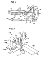
FIG. 9 shows a C-arm support unit used in a conventional circulatory-organ X-ray diagnostic apparatus. AnX-ray generator 1101 is mounted to an end (the lower end) of a C-arm 1103 of the C-arm support unit 1110, while anX-ray detector 1102 having a plane detection element is mounted to the other end (the upper end) in such a manner as to face theX-ray generator 1101. The alternate long and short dash line 1108 in the drawing indicates an exposure axis connecting the focus of the X-ray tube in theX-ray generator 1101 and the center of the plane detection element of theX-ray detector 1102. The alternate long and short dash line indicates also the center line of atabletop 1107 in a lateral reference position, or a base line BL for exposure which substantially agrees with the body axis of the subject. - The C-
arm 1103 is retained by astand 1105 installed on afloor 1106 through anarm holder 1104. The C-arm 1103 is mounted to an end of thearm holder 1104 slidably in the direction indicated by arrow a. Thearm holder 1104 is mounted to the top of thestand 1105 in such a manner as to turn or rotate in the direction indicated by arrow b. Thestand 1105 is composed of astand fixing section 1105a fixed to thefloor 1106 and astand moving section 1105b that is rotatable in the direction of arrow c about the support axis. - The
X-ray generator 1101 and the X-ray detector 1102 (hereinafter, collectively referred to as an imaging system) are set in a position and direction suitable for a subject (not shown) laid on thetabletop 1107 by the sliding of the C-arm 1103 in the direction a and the rotation of thearm holder 1104 in the direction b. Turning thestand moving section 1105b in the direction c enables the imaging system and the C-arm 1103 to be separated from the subject. The separation of the imaging system and the C-arm 1103 provides a working space for a doctor or a medical technologist (hereinafter, referred to as an operator) around the head of the subject, thus facilitating rearrangement of the subject on thetabletop 1107 or turn of the position before and after the examination, and placement of anesthetic equipment. - An L-shaped offset arm, as shown in
FIG. 9 , is generally used as thearm holder 1104. Forming thearm holder 1104 in L-shape enables the C-arm 1103 to be mounted on the side of thetabletop 1107, thus permitting the longitudinal end of thetabletop 1107 to be moved in the direction of arrow d to the vicinity of thestand 1105. In other words, the use of the L-shaped arm holder 1104 increases the moving range of thetabletop 1107, thereby increasing the subject distance. The use of the L-shaped arm holder 1104 also has the advantage of providing enough working space for the operator around the subject's head. - However, the provision of working space and increase of the subject distance by the rotation of the
stand moving section 1105b or the L-shaped arm holder 1104 have limitation because thestand 1105 is fixed on thefloor 1106, which is not always enough for the operator. - To solve the above problems, a ceiling-mounted C-arm support unit is proposed in which an arm holder is fixed to an end of an arm that is rotatably fixed at the other end to the ceiling, and in which the exposure region of the subject to can be set freely by bringing the rotation axis of the arm into agreement with the longitudinal center of the tabletop (for example, refer to
JP-A-2000-70248 - It is an object of the present invention to improve the operability of radiography in controlling an X-ray diagnostic apparatus having a floor C-arm.
- According to an aspect of the invention, A method for controlling an X-ray diagnostic apparatus comprising a floor-mounted rotary arm mounted at one end on a floor rotatably about a substantially vertical rotation axis; a stand supported at the other end of the floor-mounted rotary arm rotatably about a substantially vertical rotation axis; a substantially C-shaped arm slidably supported by the stand; an X-ray tube supported at one end of the C-arm; an X-ray detector supported at the other end of the C-arm rotatably about a shooting axis passing through the X-ray focus of the X-ray tube and the center of the detection surface; and a controller for controlling the components of the apparatus, the method comprising the steps of: moving the X-ray tube and the X-ray detector linearly by controlling the rotation of the floor-mounted rotary arm and the rotation of the stand; and maintaining the erection of the image in a display screen by controlling the axial rotation of the X-ray detector in synchronization with the rotation of the floor-mounted rotary arm and the rotation of the stand is provided.
-
-
FIG. 1 is an external view of a C-arm support unit of an X-ray diagnostic system according to an embodiment of the invention; -
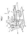
FIG. 2 is an external view of the C-arm support unit of the X-ray diagnostic system according to the embodiment of the invention; -
FIG. 3 is a functional block diagram of the principal part of the X-ray diagnostic system according to the embodiment of the invention; -
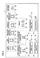
FIG. 4 is a diagram of an example of the operation screen of the operating section ofFIG. 3 ; -
FIG. 5A is a diagram showing a reference position controlled by the moving-mechanism drive controller ofFIG. 3 ; -
FIG. 5B is a diagram showing a right-head approach position controlled by the moving-mechanism drive controller ofFIG. 3 ; -
FIG. 5C is a diagram showing a left-head approach position controlled by the moving-mechanism drive controller ofFIG. 3 ; -
FIG. 6A is a plan view of a head free approach position controlled by the moving-mechanism drive controller ofFIG. 3 ; -
FIG. 6B is a perspective view of the head free approach position controlled by the moving-mechanism drive controller ofFIG. 3 ; -
FIG. 7A is a diagram of the shift of a shooting axis achieved by the synchronous control of the moving-mechanism drive controller ofFIG. 3 ; -
FIG. 7B is a diagram of the lateral shift of the shooting axis achieved by the synchronous control of the moving-mechanism drive controller ofFIG. 3 ; -
FIG. 7C is a diagram of the head-to-toe shift of the shooting axis achieved by the synchronous control of the moving-mechanism drive controller ofFIG. 3 ; -
FIG. 8 is a diagram of an oblique exposure position controlled by the moving-mechanism drive controller ofFIG. 3 ; and -
FIG. 9 is an external view of a floor-mounted C-arm support unit of a related art. - Embodiments of the invention will be described with reference to the drawings.
- Referring to
FIGS. 1 and2 , a floor-mountedrotary arm 54 is mounted on afloor 59 in such a manner as to rotate (d) at on end about a substantially vertical first rotation axis Z1. The first rotation axis Z1 is a vertical axis orthogonal to a horizontal base line BL. During exposure, asubject 150 is laid on atabletop 17 in such a manner that the body axis of thesubject 150 substantially agrees with the base line BL. The base line BL substantially agrees with the center line of thetabletop 17. Thetabletop 17 is disposed on abed 18 in such a manner as to be movable along the length parallel to the base line BL. The first rotation axis Z1 crosses the base line BL within the longitudinal moving range MR of thetabletop 17. That is, the floor-mountedrotary arm 54 is disposed in the longitudinal moving range MR. - A
stand 53 is supported at the other end of the floor-mountedrotary arm 54 in such a manner as to be rotatable (c) about a substantially vertical second rotation axis Z2. Thestand 53 supports anarm holder 52 in such a manner as to be rotatable (b) about a substantially horizontal third rotation axis (C-arm horizontal rotation axis) Z3. Thearm holder 52 supports a substantially C-shapedarm 51 in such a manner as to be slidably rotatable (a) about a substantially horizontal fourth rotation axis (sliding rotation axis) Z4 orthogonal to the C-arm horizontal rotation axis Z3. A C-arm 51 is fitted at one end with anX-ray generator 1. The C-arm 51 has at the other end an X-ray detector (commonly referred to as a flat panel detector (FPD)) 2 which typically has a plurality of two-dimensional-array X-ray detecting semiconductor devices. - Referring to
FIG. 5A , theX-ray generator 1 and theX-ray detector 2 are disposed with an offset of zero from the C-arm 51 so that the center line CL of the C-arm 51 agrees with the shooting axis SA connecting the X-ray focus of the X-ray tube and the center of the detection surface of theX-ray detector 2, that is, the shooting axis SA connecting the X-ray focus of the X-ray tube and the center of the detection surface of theX-ray detector 2 is located in the plane passing through the center line CL of the C-arm 51. - Although not shown, the
X-ray generator 1 includes an X-ray tube and an X-ray limiting mechanism that forms the X-ray irradiation field into a desired shape such as a rectangle or a circle. The X-ray limiting mechanism is supported by an axial rotation mechanism 515-1 (seeFIG. 3 ) in such a manner as to be rotatable about the shooting axis SA (in agreement with the fifth rotation axis Z5) connecting the X-ray focus of the X-ray tube and the center of the detection surface of theX-ray detector 2. Similarly, theX-ray detector 2 is supported by an axial rotation mechanism 515-2 in such a manner as to be rotatable about the shooting axis SA (in agreement with the fifth rotation axis Z5). When the X-ray limiting mechanism forms the X-ray irradiation field into the shape of a circle, there is necessarily no need to rotate the X-ray limiting mechanism about the shooting axis SA (in agreement with the fifth rotation axis Z5) to erect an image. - The apparatus is designed such that the shooting axis SA (Z5) passing through the X-ray focus of the
X-ray generator 1 and the center of the detection surface of theX-ray detector 2 cross the C-arm horizontal rotation axis Z3 and the slide rotation axis Z4 at one point. As well known, the absolute coordinates of the intersection point (the position on the coordinate system of the exposure room) do not change unless thestand 53 turns on the second rotation axis Z2 even when the C-arm 51 rotates about the C-arm horizontal rotation axis Z3, even when the C-arm 51 rotates about the slide rotation axis Z4, or even when the floor-mountedrotary arm 54 rotates about the first rotation axis Z1. The absolute coordinates are generally called an isocenter IS. - Referring to
FIG. 1 , the apparatus is designed such that when the turning angle of thestand 53 about the second rotation axis Z2 is at the reference angle (0°), so that the C-arm 51 overlaps over the floor-mountedrotary arm 54 to the smallest, the isocenter is located on the first rotation axis Z1 of the floor-mountedrotary arm 54, in other words, such that the shooting axis SA (Z5), the C-arm horizontal rotation axis Z3, and the slide rotation axis Z4 intersect the first rotation axis Z1 of the floor-mountedrotary arm 54 on the isocenter. That is, the length of the floor-mountedrotary arm 54, the size of thestand 53, the size of thearm holder 52, and the radius of the C-arm 51 are totally determined so that the distance between the first rotation axis Z1 of the floor-mountedrotary arm 54 and the second rotation axis Z2 of thestand 53 and the distance between the second rotation axis Z2 of thestand 53 and the isocenter IS are the same. - With this design, when the rotation angle of the C-
arm 51 about the C-arm horizontal rotation axis Z3 is at the reference angle (0°), and moreover, when the rotation angle of the C-arm 51 about the slide rotation axis Z4 is at the reference angle (0°), so that the shooting axis SA (Z5) is in the vertical direction, the shooting axis SA (Z5) substantially agrees with the first rotation axis Z1 of the floor-mountedrotary arm 54 in the case in which the turning angle of thestand 53 about the second rotation axis Z2 is at the reference angle (0°). - Referring to
FIG. 3 , typically, driving signals are respectively supplied fromdrivers mechanisms arm support unit 5 under the control of a moving-mechanism drive controller 33 of a moving-mechanism driver 3 in response to the control signals from asystem controller 10 or operating signals from anoperating section 9. Thus, the components are rotated or slid. Similarly, a driving signal is supplied from a tabletop-mechanism driver 32 to a longitudinal-lateral shift mechanism 171 and avertical shift mechanism 172 of thetabletop 17 under the control of the moving-mechanism drive controller 33 of the moving-mechanism driver 3 in response to the control signal from asystem controller 10 or the operating signal from theoperating section 9. Thus, the brake of thetabletop 17 is released to be able to move in the longitudinal direction f (in the Y-direction) or in the lateral direction (in the X-direction), or thetabletop 17 can be moved in the vertical direction g. -
FIG. 4 shows the operation screen of anoperating section 11. The operation screen may be either a touch panel or an operator console in which substantial switches or buttons are arranged. The operation screen hasmanual operation buttons 211 to 227, 233, and 234 for manually controlling the movement of the components. The operation screen also has presetbuttons arm support unit 5 in a predetermined position. - When the floor-mounted-
arm turning button 211 is clicked or pressed, thecontroller 33 controls a driver 31 so that the floor-mountedrotary arm 54 is turned forward (counterclockwise) about the rotation axis Z1 by the floor-mounted-armrotating mechanism 514 by an angle corresponding to the operation amount, typically, pressing time. When the floor-mounted-arm turning button 212 is clicked or pressed, thecontroller 33 controls the driver 31 so that the floor-mountedrotary arm 54 is turned backward (clockwise) about the rotation axis Z1 by the floor-mounted-armrotating mechanism 514 by an angle corresponding to the operation amount. - When the
stand turning button 213 is clicked or pressed, thecontroller 33 controls a driver 31 so that thestand 53 is turned forward (counterclockwise) about the rotation axis Z2 by thestand turning mechanism 513 by an angle corresponding to the operation amount. When thestand turning button 214 is clicked or pressed, thecontroller 33 controls the driver 31 so that thestand 53 is turned backward (clockwise) about the rotation axis Z2 by thestand turning mechanism 513 by an angle corresponding to the operation amount. - When the arm-holder horizontally turning
button 215 is clicked or pressed, thecontroller 33 controls a driver 31 so that thearm holder 52 is turned forward horizontally about the rotation axis Z3 by the arm-holder turning mechanism 512 by an angle corresponding to the operation amount. When the arm-holder horizontally turningbutton 216 is clicked or pressed, thecontroller 33 controls the driver 31 so that thearm holder 52 is turned backward horizontally about the rotation axis Z3 by the arm-holder turning mechanism 512 by an angle corresponding to the operation amount. - When the C-arm slide
rotating button 217 is clicked or pressed, thecontroller 33 controls a driver 31 so that the C-arm 51 is slid forward about the rotation axis Z4 and along thearm holder 52 by the C-arm sliding mechanism 511 by an angle corresponding to the operation amount. When the C-arm sliderotating button 218 is clicked or pressed, thecontroller 33 controls the driver 31 so that the C-arm 51 is slid backward about the rotation axis Z4 and along thearm holder 52 by the C-arm sliding mechanism 511 by an angle corresponding to the operation amount. - When the X-ray-tube/
detector rotating button 219 is clicked or pressed, thecontroller 33 controls a driver 31 so that the X-ray limiting device rotates forward about the rotation axis Z5 (shooting axis SA) together with theX-ray detector 2 by an angle corresponding to the operation amount in synchronism with the axial rotation mechanisms 515-1 and 515-2. When the X-ray-tube/detector rotating button 220 is clicked or pressed, thecontroller 33 controls the driver 31 so that the X-ray limiting device rotates backward about the rotation axis Z5 (shooting axis SA) together with theX-ray detector 2 by an angle corresponding to the operation amount in synchronism with the axial rotation mechanisms 515-1 and 515-2. - When the
tabletop operating button 225 is clicked or pressed, thecontroller 33 controls thedriver 32 so that thetabletop 17 rises along a vertical axis by a distance corresponding to the operation amount by the vertically movingmechanism 172. When thetabletop operating button 226 is clicked or pressed, thecontroller 33 controls thedriver 32 so that thetabletop 17 falls along the vertical axis by a distance corresponding to the operation amount by the vertically movingmechanism 172. When thetabletop brake button 227 is clicked or pressed, the brake is released to enable thetabletop 17 to be moved in the longitudinal direction (the Y-direction) or in the lateral direction (the X-direction). When thetabletop brake button 227 is clicked or pressed again after the tabletop is moved, thetabletop 17 is braked. - When the
SID change button 233 is clicked or pressed, thecontroller 33 controls theSID change mechanism 516 so as to synchronously separate theX-ray tube 1 and theX-ray detector 2 from the isocenter IS along the shooting axis SA by a distance corresponding to the operation amount to increase the SID (the distance between theX-ray tube 1 and the X-ray detector 2). When theSID change button 234 is clicked or pressed, thecontroller 33 controls theSID change mechanism 516 so as to synchronously bring theX-ray tube 1 and theX-ray detector 2 close to the isocenter IS along the shooting axis SA by a distance corresponding to the operation amount to decrease the SID (the distance between theX-ray tube 1 and the X-ray detector 2). - When the lateral
linear shift button 221 is clicked or pressed, thecontroller 33 controls thedrivers X-ray tube 1 and theX-ray detector 2 together with the C-arm 51 linearly substantially in parallel with the straight line WL in such a manner that the shooting axis SA shifts from initial position, shown inFIG. 7A , to the left by a distance corresponding to the operation amount while maintaining the intersection with the straight line WL orthogonal to the base line BL (seeFIG. 7B ). Thecontroller 33 controls the rotation of the floor-mountedrotary arm 54 about the rotation axis Z1 and the turn of thestand 53 about the rotation axis Z2 so as to shift the shooting axis SA linearly. Actually, the relationship between the rotation angle of the floor-mountedrotary arm 54 and that of thestand 53 for locating the shooting axis SA on the straight line WL is determined in advance. Thecontroller 33 individually controls the rotation of the floor-mountedrotary arm 54 and the turn of thestand 53 according to the relationship. Of course, thecontroller 33 may turn thestand 53 in connection with the rotation of the floor-mountedrotary arm 54 so as to locate the shooting axis SA on the straight line WL. Thecontroller 33 may also rotate the floor-mountedrotary arm 54 in synchronization with the turn of thestand 53 so as to locate the shooting axis SA on the straight line WL. Although the floor-mountedrotary arm 54 and thestand 53 typically rotate at the same time, the floor-mountedrotary arm 54 and thestand 53 may be rotated alternately. - Furthermore, in order to prevent the turn of the image associated with the rotation of the floor-mounted
rotary arm 54 about the rotation axis Z1 and the rotation of thestand 53 about the rotation axis Z2 to maintain the erection of the image, thecontroller 33 controls the X-ray limiting device and the X-ray detector to rotate about the rotation axis Z5 (shooting axis SA) by the axial rotation mechanisms 515-1 and 515-2 in synchronism with the rotation of the floor-mountedrotary arm 54 about the rotation axis Z1 and the rotation of thestand 53 about the rotation axis Z2. When the X-ray flux by the X-ray limiting device is circular, there is no need to rotate the X-ray limiting device. Only the X-ray detector may be rotated with the rotation of the floor-mountedrotary arm 54 and thestand 53. - Similarly, when the lateral
linear shift button 222 is clicked or pressed, thecontroller 33 controls thedrivers X-ray tube 1 and theX-ray detector 2 together with the C-arm 51 linearly substantially in parallel with the straight line WL in such a manner that the shooting axis SA shifts to the right by a distance corresponding to the operation amount while maintaining the intersection with the straight line WL. Thecontroller 33 controls the rotation of the floor-mountedrotary arm 54 about the rotation axis Z1 and the turn of thestand 53 about the rotation axis Z2 so as to shift the shooting axis SA linearly. Actually, the relationship between the rotation angle of the floor-mountedrotary arm 54 and that of thestand 53 for locating the shooting axis SA on the straight line WL is determined in advance. Thecontroller 33 individually controls the rotation of the floor-mountedrotary arm 54 and the turn of thestand 53 according to the relationship. Of course, thecontroller 33 may turn thestand 53 in connection with the rotation of the floor-mountedrotary arm 54 so as to locate the shooting axis SA on the straight line WL. Thecontroller 33 may also rotate the floor-mountedrotary arm 54 in synchronization with the turn of thestand 53 so as to locate the shooting axis SA on the straight line WL. Although the floor-mountedrotary arm 54 and thestand 53 typically rotate at the same time, the floor-mountedrotary arm 54 and thestand 53 may be rotated alternately. - Furthermore, in order to prevent the turn of the image associated with the rotation of the floor-mounted
rotary arm 54 about the rotation axis Z1 and the rotation of thestand 53 about the rotation axis Z2 to fix the orientation of the image, thecontroller 33 controls the X-ray limiting device and the X-ray detector to rotate about the rotation axis Z5 (shooting axis SA) by the axial rotation mechanisms 515-1 and 515-2 in synchronization with the rotation of the floor-mountedrotary arm 54 about the rotation axis Z1 and the rotation of thestand 53 about the rotation axis Z2. - Since the rotation of the floor-mounted
rotary arm 54 and the rotation of thestand 53 are operatively associated, a wide coverage across the width of the patient can be provided even with the floor-fixed support unit. An example of the characteristic arrangements is a patient upper-arm position. The sequence to the position is as follows: thearm 51 is set in a patient's head position and moved in a desired right or left position by a manual/auto positioning operation. Specifically, thearm 54 is turned to thereby set thearm 51 in the patient's head position. The floor-mountedrotary arm 54 and thestand 53 are turned in association with each other to move the patient to the right or left. A possible motion of thearm 51 is to linearly move across the width of the patient by the interconnected turns of the floor-mountedrotary arm 54 and thestand 53 by one action of thebutton X-ray detector 2 and the X-ray limiting device are controlled so as to erect the image constantly, thus eliminating the need for manual setting. The rotation angles may be set manually at desired angles. An example of characteristic motions that can be made from the apparatus during examination/surgical operation after the arrangement is an approach from the upper arm. The increase in the lateral stroke allows the approach from the upper arm, the case of which is recently increasing. Since the X-ray limiting device and theX-ray detector 2 can be turned freely, unnecessary exposure when the arms are inclined can be prevented. - When the head-to-toe
linear shift button 223 is clicked or pressed, thecontroller 33 controls thedrivers X-ray tube 1 and theX-ray detector 2 together with the C-arm 51 linearly substantially in parallel with the base line BL (seeFIG. 7C ). - The
controller 33 controls the rotation of the floor-mountedrotary arm 54 about the rotation axis Z1 and the rotation of thestand 53 about the rotation axis Z2 so as to shift the shooting axis SA linearly. Actually, the relationship between the rotation angle of the floor-mountedrotary arm 54 and that of thestand 53 for locating the shooting axis SA on the base line BL is determined in advance. Thecontroller 33 individually controls the rotation of the floor-mountedrotary arm 54 and the rotation of thestand 53 according to the relationship. Of course, thecontroller 33 may turn thestand 53 in synchronization with the rotation of the floor-mountedrotary arm 54 so as to locate the shooting axis SA on the base line BL. Thecontroller 33 may also rotate the floor-mountedrotary arm 54 in synchronization with the rotation of thestand 53 so as to locate the shooting axis SA on the base line BL. Although the floor-mountedrotary arm 54 and thestand 53 typically rotates at the same time, the floor-mountedrotary arm 54 and thestand 53 may be rotated alternately. The head-to-toe linear movement of the floor-mountedrotary arm 54 can be made on either side of the right and left of the subject. Which side the floor-mountedrotary arm 54 is disposed depends on the instruction of the operator. - Furthermore, in order to prevent the turn of the image associated with the rotation of the floor-mounted
rotary arm 54 about the rotation axis Z1 and the rotation of thestand 53 about the rotation axis Z2 to fix the orientation of the image, thecontroller 33 controls the drivers 315-1 and 315-2 to turn the X-ray limiting device and the X-ray detector about the rotation axis Z5 (shooting axis SA) by the axial rotation mechanisms 515-1 an 515-2 in synchronization with the rotation of the floor-mountedrotary arm 54 about the rotation axis Z1 and the rotation of thestand 53 about the rotation axis Z2. - When the head-to-toe
linear shift button 224 is clicked or pressed, thecontroller 33 controls thedrivers X-ray tube 1 and theX-ray detector 2 together with the C-arm 51 linearly substantially in parallel with the base line BL. Thecontroller 33 controls the rotation of the floor-mountedrotary arm 54 about the rotation axis Z1 and the rotation of thestand 53 about the rotation axis Z2 so as to shift the shooting axis SA linearly. Actually, the relationship between the rotation angle of the floor-mountedrotary arm 54 and that of thestand 53 for locating the shooting axis SA on the base line BL is determined in advance. Thecontroller 33 individually controls the rotation of the floor-mountedrotary arm 54 and the rotation of thestand 53 according to the relationship. Of course, thecontroller 33 may turn thestand 53 in synchronization with the rotation of the floor-mountedrotary arm 54 so as to locate the shooting axis SA on the base line BL. Thecontroller 33 may also rotate the floor-mountedrotary arm 54 in synchronization with the rotation of thestand 53 so as to locate the shooting axis SA on the base line BL. Although the floor-mountedrotary arm 54 and thestand 53 typically rotate at the same time, the floor-mountedrotary arm 54 and thestand 53 may be rotated alternately. - Furthermore, in order to prevent the turn of the image associated with the rotation of the floor-mounted
rotary arm 54 about the rotation axis Z1 and the rotation of thestand 53 about the rotation axis Z2 to fix the orientation of the image, thecontroller 33 controls the drivers 315-1 and 315-2 to turn the X-ray limiting device and the X-ray detector about the rotation axis Z5 (shooting axis SA) by the axial rotation mechanisms 515-1 an 515-2 in synchronization with the rotation of the floor-mountedrotary arm 54 about the rotation axis Z1 and the rotation of thestand 53 about the rotation axis Z2. - Since the rotation of the floor-mounted
rotary arm 54 and the rotation of thestand 53 are operatively associated, a wide coverage across the length of the patient can be provided even with the floor-fixed support unit. An example of the characteristic arrangements is a patient's leg position. The sequence to the position is as follows: thearm 51 is set in the patient's leg position by a manual/auto positioning operation. The floor-mountedrotary arm 54 is turned to the right or left of the patient. The floor-mountedrotary arm 54 and thestand 53 are turned in synchronization with each other to move theX-ray tube 1 and theX-ray detector 2 toward the legs. A possible motion of thearm 51 in this arrangement is to linearly move theX-ray tube 1 and theX-ray detector 2 across the length of the patient by the interconnected rotations of the floor-mountedrotary arm 54 and thestand 53 by one action of thebutton X-ray detector 2 and the X-ray limiting device are controlled so as to erect the image constantly, thus eliminating the need for manual setting. Examples of characteristic motions that can be made from the apparatus during examination/surgical operation after the arrangement include longitudinal scanning and digital subtraction angiography (DSA) of legs only by arm operation without moving the bed. Retracting thearm 51 to the patient's toes as much as possible to clear the surrounding of the patient allows compatibility with surgical operation that needs no radiography. This makes it possible to cope with pediatric cases in which switching to surgical operation may occur. - When the right-head-
approach position button 229 is clicked or pressed, thecontroller 33 controls thedrivers arm support unit 5 is set in a predetermined position suitable for increasing the work space for the operator to approach the subject 150 from the right head, as shown inFIGS. 5A and 5B . Specifically, since thestand 53 is turned to the reference position, the C-arm 51 comes over the floor-mountedrotary arm 54. That is, a second position line PL2 connecting the second rotation axis Z2 and the fifth rotation axis Z5 (shooting axis SA) agrees with a first position line PL1 connecting the first rotation axis Z1 and the second rotation axis Z2. Therefore, the fifth rotation axis Z5 (shooting axis SA) of the X-ray limiting device and theX-ray detector 2 substantially agrees with the first rotation axis Z1 of the floor-mountedrotary arm 54. Furthermore, the first and second position lines PL1 and PL2 are inclined positively substantially at 45 degrees with respect to the base line BL. Thecontroller 33 controls thedriver 314 to rotate the floor-mountedrotary arm 54 about the first rotation axis Z1 with thestand 53 at zero degree about the second rotation axis Z2 so as to have such a preset position. This position provides a wide work space sufficient for the operator to approach the right head of the subject 150. The position is automatically set by the operation of the right-head-approach position button 229, allowing quick shift to the position. The inclination angle is finely controlled by the manual operation with thebutton controller 33 controls the orientation of the image according to the rotation of the X-ray detector 2 (FPD) and the X-ray limiting device. The preset angle can be changed as appropriate by setting. - When the left-head-
approach position button 230 is clicked or pressed, thecontroller 33 controls thedrivers arm support unit 5 is set in a predetermined position suitable for increasing the work space for the operator to approach the subject 150 from the left head, as shown inFIGS. 5A and 5C . Specifically, similarly to the right-head approach position, the C-arm 51 comes over the floor-mountedrotary arm 54 to make the shooting axis Z5 substantially agree with the rotation axis Z1. Furthermore, the first and second position lines PL1 and PL2 are inclined negatively substantially at 45 degrees with respect to the base line BL. Thecontroller 33 controls thedriver 314 to rotate the floor-mountedrotary arm 54 about the first rotation axis Z1 with thestand 53 at zero degree about the second rotation axis Z2 so as to have such a preset position. This position provides a wide work space sufficient for the operator to approach the left head of the subject 150. The position is automatically set by the operation of the left-head-approach position button 230, allowing quick shift to the position. The inclination angle is finely controlled by the manual operation with thebutton controller 33 controls the orientation of the image according to the rotation of the X-ray detector 2 (FPD) and the X-ray limiting device. The preset angle can be changed as appropriate by setting. - When the head-free-
approach position button 231 is clicked or pressed, thecontroller 33 controls thedrivers arm support unit 5 is set in a predetermined position suitable for increasing the work space for the operator to approach the subject 150 from all around the head, as shown inFIGS. 6A and 6B . The position in which the work space is provided all around the head is typically advantageous for biplane imaging in combination with a ceiling-mounted Ω-arm 101 having anX-ray generator 105 and anX-ray detector 103 at both horizontal ends, respectively. - Specifically, similarly to the right-head approach position, the C-
arm 51 comes over the floor-mountedrotary arm 51. Furthermore, the first and second position lines PL1 and PL2 are inclined positively or negatively substantially at 135 degrees with respect to the base line BL. Thecontroller 33 controls thedriver 314 to rotate the floor-mountedrotary arm 54 about the first rotation axis Z1 with thestand 53 at zero degree about the second rotation axis Z2 so as to have such a preset position. This position provides a wide work space sufficient for the operator to approach all around the head of the subject 150. The position is automatically set by the operation of the head-free-approach position button 231, allowing quick shift to the position. The inclination angle is finely controlled by the manual operation with thebutton controller 33 controls the orientation of the image according to the rotation of the X-ray detector 2 (FPD) and the X-ray limiting device. The preset angle can be changed as appropriate by setting. - This rotation of the C-
arm 51 between the Ω-arm 101 and thetabletop 17 during biplane imaging clears the vicinity of the head completely. An example of the characteristic arrangements is a biplane complete head free position. The sequence to the position is as follows: the Ω-arm 101 is moved to a retracted position; the Ω-arm 101 is then rotated on the floor into a position about 110 degrees or more to the left from the patient. Then, the Ω-arm 101 is moved from the retracted position to the biplane set position. When the operator is on the left of the patient, the C-arm 51 is moved to the right symmetric position. This position allows an arm motion in the direction, RAO/LAO or CRA/CAU, by one action of clinical angular control, and synchronous operation of the C-arm 51 and the Ω-arm 101. TheX-ray detector 2 and the X-ray limiting device are controlled so as to erect the image constantly, thus eliminating the need for manual setting. This arrangement enables the periphery of the head to be completely cleared, thus having an advantage in installing a general anesthetic apparatus and making an approach to the right and left carotid arteries during examination/surgical operation after arrangement and facilitating patient access of medical staff. This arrangement also provides the same operability and angles as normal biplane setting. Switching to surgical operation for brain cases can be made only by moving thetabletop 17 in the longitudinal direction. - When the oblique exposing
position button 232 is clicked or pressed, thecontroller 33 controls the driver 31 so that the C-arm support unit 5 is set in a position (in which the subject 150 is imaged in a slanting direction from between the front and the side) suitable for inserting the subject 150 from the head into an exposure region, as shown inFIG. 8 . Specifically, the second position line PL2 connecting the second rotation axis Z2 and the fifth rotation axis Z5 (shooting axis SA) agrees with the first position line PL1 connecting the first rotation axis Z1 and the second rotation axis Z2, so that the C-arm 51 is placed over the floor-mountedrotary arm 51. The C-arm 51 rotates about the rotation axis Z4 and the rotation axis Z3 at predetermined angles, respectively, so that the shooting axis SA obliquely crosses the base line BL. Furthermore, the X-ray limiting device and theX-ray detector 2 are rotated at a predetermined angle about the rotation axis Z5, thereby allowing the image to be oriented appropriately. Also for oblique exposure, a sufficient wide work space and a head position can be provided. The position is automatically set by the operation with theposition button 232, allowing quick shift to the position. The inclination angle is finely controlled by the manual operation with thebuttons 211 to 218 as necessary. There is no need to provide thededicated buttons - It is to be understood that the invention is not limited to the embodiments and that various modifications may be made without departing from the spirit and scope thereof. It is to be further understood that the invention may be variously modified in appropriate combinations of the components of the embodiments. For example, several components may be omitted from all the components of the embodiments. Furthermore, the components of the different embodiments may be combined as appropriate.
- The invention can improve the operability of radiography imaging in a method for controlling an X-ray diagnostic apparatus having a floor-mounted C-arm.
Claims (16)
- A method for controlling an X-ray diagnostic apparatus comprising a floor-mounted rotary arm mounted at one end on a floor rotatably about a substantially vertical rotation axis; a stand supported at the other end of the floor-mounted rotary arm rotatably about a substantially vertical rotation axis; a substantially C-shaped arm slidably supported by the stand; an X-ray tube supported at one end of the C-arm; an X-ray detector supported at the other end of the C-arm rotatably about a shooting axis passing through the X-ray focus of the X-ray tube and the center of the detection surface; and a controller for controlling the components of the apparatus, the method comprising the steps of:moving the X-ray tube and the X-ray detector linearly by controlling the rotation of the floor-mounted rotary arm and the rotation of the stand; andmaintaining the erection of the image in a display screen by controlling the axial rotation of the X-ray detector in synchronization with the rotation of the floor-mounted rotary arm and the rotation of the stand.
- A method for controlling an X-ray diagnostic apparatus comprising a floor-mounted rotary arm mounted at one end on a floor rotatably about a substantially vertical rotation axis; a stand supported at the other end of the floor-mounted rotary arm rotatably about a substantially vertical rotation axis; a substantially C-shaped arm slidably supported by the stand; an X-ray tube supported at one end of the C-arm; an X-ray detector supported at the other end of the C-arm rotatably about a shooting axis passing through the X-ray focus of the X-ray tube and the center of the detection surface; and a controller for controlling the components of the apparatus, the method comprising the steps of:controlling the rotation of the floor-mounted rotary arm;moving the X-ray tube and the X-ray detector linearly by controlling the rotation of the stand in synchronization with the rotation of the floor-mounted rotary arm; andmaintaining the erection of the image in a display screen by controlling the axial rotation of the X-ray detector in synchronization with the rotation of the floor-mounted rotary arm.
- A method for controlling an X-ray diagnostic apparatus comprising a floor-mounted rotary arm mounted at one end on a floor rotatably about a substantially vertical rotation axis; a stand supported at the other end of the floor-mounted rotary arm rotatably about a substantially vertical rotation axis; a substantially C-shaped arm slidably supported by the stand; an X-ray tube supported at one end of the C-arm; an X-ray detector supported at the other end of the C-arm rotatably about a shooting axis passing through the X-ray focus of the X-ray tube and the center of the detection surface; and a controller for controlling the components of the apparatus, the method comprising the steps of:controlling the rotation of the stand;moving the X-ray tube and the X-ray detector linearly by controlling the rotation of the floor-mounted rotary arm in synchronization with the rotation of the stand; andmaintaining the erection of the image in a display screen by controlling the axial rotation of the X-ray detector in synchronization with the rotation of the stand.
- A method for controlling an X-ray diagnostic apparatus comprising a floor-mounted rotary arm mounted at one end on a floor rotatably about a substantially vertical rotation axis; a stand supported at the other end of the floor-mounted rotary arm rotatably about a substantially vertical rotation axis; a substantially C-shaped arm slidably supported by the stand; an X-ray tube supported at one end of the C-arm; an X-ray detector supported at the other end of the C-arm; and a controller for controlling the components of the apparatus, the method comprising the steps of:controlling the rotation of the floor-mounted rotary arm; andmoving the X-ray tube and the X-ray detector linearly by controlling the rotation of the stand in synchronization with the rotation of floor-mounted rotary arm.
- A method for controlling an X-ray diagnostic apparatus comprising a floor-mounted rotary arm mounted at one end on a floor rotatably about a substantially vertical rotation axis; a stand supported at the other end of the floor-mounted rotary arm rotatably about a substantially vertical rotation axis; a substantially C-shaped arm slidably supported by the stand; an X-ray tube supported at one end of the C-arm; an X-ray detector supported at the other end of the C-arm rotatably about a shooting axis passing through the X-ray focus of the X-ray tube and the center of the detection surface; and a controller for controlling the components of the apparatus, the method comprising the steps of:controlling the rotation of the stand; andmoving the X-ray tube and the X-ray detector linearly by controlling the rotation of the floor-mounted rotary arm in synchronization with the rotation of the stand.
- The method for controlling the X-ray diagnostic apparatus according to claim 1, wherein the shooting axis can be made substantially agree with the floor-mounted rotary arm.
- The method for controlling the X-ray diagnostic apparatus according to claim 1, further comprising the step of controlling the rotation of the stand so that the shooting axis substantially agrees with the floor-mounted rotary arm according to the instruction of a specific operator.
- A method for controlling an X-ray diagnostic apparatus comprising: a tabletop movably supported along a reference line; a floor-mounted rotary arm mounted at one end on a floor rotatably about a substantially vertical first rotation axis intersecting the reference line within the movable range of the tabletop; a driver of the rotation of the floor-mounted rotary arm; a stand supported at the other end of the floor-mounted rotary arm rotatably about a substantially vertical second rotation axis; a driver of the rotation of the stand; a substantially C-shaped arm supported by the stand; an X-ray tube supported at one end of the C-arm; an X-ray detector supported at the other end of the C-arm rotatably about a third rotation axis that substantially agrees with a shooting axis passing through the X-ray focus of the X-ray tube and the center of the detection surface; a driver of the rotation of the X-ray detector; and a controller for controlling the components of the apparatus, the method comprising the steps of:moving the X-ray tube and the X-ray detector linearly substantially in parallel with the reference line by controlling the floor-mounted-rotary-arm rotation driver and the stand rotation driver; androtating the X-ray detector in synchronization with the rotation of the floor-mounted rotary arm and the rotation of the stand by controlling the X-ray-detector rotation driver in such a manner as to maintain the erection of the image in a display screen.
- A method for controlling an X-ray diagnostic apparatus comprising: a tabletop movably supported along a reference line; a floor-mounted rotary arm mounted at one end on a floor rotatably about a substantially vertical first rotation axis intersecting the reference line within the movable range of the tabletop; a driver of the rotation of the floor-mounted rotary arm; a stand supported at the other end of the floor-mounted rotary arm rotatably about a substantially vertical second rotation axis; a driver of the rotation of the stand; a substantially C-shaped arm supported by the stand; an X-ray tube supported at one end of the C-arm; an X-ray detector for forming an image, the X-ray detector being supported at the other end of the C-arm rotatably about a third rotation axis that substantially agrees with a shooting axis passing through the X-ray focus of the X-ray tube and the center of the detection surface; a driver of the rotation of the X-ray detector; and a controller for controlling the components of the apparatus, the method comprising the steps of:rotating the floor-mounted rotary arm about the first rotation axis by controlling the driver of the rotation of the floor-mounted rotary arm;rotating the stand about the second rotation axis in synchronization with the rotation of the floor-mounted rotary arm in such a manner as to move the X-ray tube and the X-ray detector linearly substantially in parallel with the reference line by controlling the stand rotation driver; androtating the X-ray detector in synchronization with the rotation of the floor-mounted rotary arm and the rotation of the stand in such a manner as to maintain the erection of the image on a display screen by controlling the X-ray-detector rotation driver.
- A method for controlling an X-ray diagnostic apparatus comprising: a tabletop movably supported along a reference line; a floor-mounted rotary arm mounted at one end on a floor rotatably about a substantially vertical first rotation axis intersecting the reference line within the movable range of the tabletop; a driver of the rotation of the floor-mounted rotary arm; a stand supported at the other end of the floor-mounted rotary arm rotatably about a substantially vertical second rotation axis; a driver of the rotation of the stand; a substantially C-shaped arm supported by the stand; an X-ray tube supported at one end of the C-arm; an X-ray detector supported at the other end of the C-arm rotatably about a third rotation axis that substantially agrees with a shooting axis passing through the X-ray focus of the X-ray tube and the center of the detection surface; a driver of the rotation of the X-ray detector; and a controller for controlling the components of the apparatus, the method comprising the steps of:rotating the stand about the second rotation axis by controlling the stand rotation driver;rotating the floor-mounted rotary arm about the first rotation axis in synchronization with the rotation of the stand in such a manner as to move the X-ray tube and the X-ray detector linearly substantially in parallel with the reference line by controlling the driver of the rotation of the floor-mounted rotary arm; androtating the X-ray detector in synchronization with the rotation of the floor-mounted rotary arm and the rotation of the stand in such a manner as to maintain the erection of the image on a display screen by controlling the X-ray-detector rotation driver.
- A method for controlling an X-ray diagnostic apparatus comprising: a tabletop movably supported along a reference line; a floor-mounted rotary arm mounted at one end on a floor rotatably about a substantially vertical first rotation axis intersecting the reference line within the movable range of the tabletop; a driver of the rotation of the floor-mounted rotary arm; a stand supported at the other end of the floor-mounted rotary arm rotatably about a substantially vertical second rotation axis; a driver of the rotation of the stand; a substantially C-shaped arm supported by the stand; an X-ray tube supported at one end of the C-arm; an X-ray detector supported at the other end of the C-arm rotatably about a third rotation axis that substantially agrees with a shooting axis passing through the X-ray focus of the X-ray tube and the center of the detection surface; a driver of the rotation of the X-ray detector; and a controller for controlling the components of the apparatus, the method comprising the steps of:rotating the floor-mounted rotary arm about the first rotation axis and rotating the stand about the second rotation axis in such a manner as to move the shooting axis while maintaining the intersection with the reference line by controlling the driver of the rotation of the floor-mounted rotary arm and the stand rotation driver; androtating the X-ray detector in synchronization with the rotation of the floor-mounted rotary arm and the rotation of the stand in such a manner as to maintain the erection of the image on a display screen by controlling the X-ray-detector rotation driver.
- A method for controlling an X-ray diagnostic apparatus comprising: a tabletop movably supported along a reference line; a floor-mounted rotary arm mounted at one end on a floor rotatably about a substantially vertical first rotation axis intersecting the reference line within the movable range of the tabletop; a driver of the rotation of the floor-mounted rotary arm; a stand supported at the other end of the floor-mounted rotary arm rotatably about a substantially vertical second rotation axis; a driver of the rotation of the stand; a substantially C-shaped arm supported by the stand; an X-ray tube supported at one end of the C-arm; an X-ray detector for forming an image supported at the other end of the C-arm rotatably about a third rotation axis that substantially agrees with a shooting axis passing through the X-ray focus of the X-ray tube and the center of the detection surface; a driver of the rotation of the X-ray detector; and a controller for controlling the components of the apparatus, the method comprising the steps of:rotating the floor-mounted rotary arm about a first rotation axis and rotating the stand about a second rotation axis in such a manner as to move the X-ray tube and the X-ray detector linearly in the direction substantially orthogonal to the reference line by controlling the driver of the rotation of the floor-mounted rotary arm and the stand rotation driver; androtating the X-ray detector in synchronization with the rotation of the floor-mounted rotary arm and the rotation of the stand in such a manner as to maintain the erection of the image on a display screen by controlling the X-ray-detector rotation driver.
- A method for controlling an X-ray diagnostic apparatus comprising: a tabletop movably supported along a reference line; a floor-mounted rotary arm mounted at one end on a floor rotatably about a substantially vertical first rotation axis intersecting the reference line within the movable range of the tabletop; a driver of the rotation of the floor-mounted rotary arm; a stand supported at the other end of the floor-mounted rotary arm rotatably about a substantially vertical second rotation axis; a driver of the rotation of the stand; a substantially C-shaped arm supported by the stand; an X-ray tube supported at one end of the C-arm; an X-ray detector for forming an image, the X-ray detector being supported at the other end of the C-arm rotatably about a third rotation axis that substantially agrees with a shooting axis passing through the X-ray focus of the X-ray tube and the center of the detection surface; a driver of the rotation of the X-ray detector; and a controller for controlling the components of the apparatus, the method comprising the steps of:rotating the floor-mounted rotary arm about the first rotation axis by controlling the driver of the rotation of the floor-mounted rotary arm; androtating the stand about the second rotation axis in synchronization with the rotation of the floor-mounted rotary arm in such a manner as to move the X-ray tube and the X-ray detector linearly in the direction substantially orthogonal to the reference line by controlling the stand rotation driver; androtating the X-ray detector in synchronization with the rotation of the floor-mounted rotary arm and the rotation of the stand in such a manner as to maintain the erection of the image on a display screen by controlling the X-ray-detector rotation driver.
- A method for controlling an X-ray diagnostic apparatus comprising: a tabletop movably supported along a reference line; a floor-mounted rotary arm mounted at one end on a floor rotatably about a substantially vertical first rotation axis intersecting the reference line within the movable range of the tabletop; a driver of the rotation of the floor-mounted rotary arm; a stand supported at the other end of the floor-mounted rotary arm rotatably about a substantially vertical second rotation axis; a driver of the rotation of the stand; a substantially C-shaped arm supported by the stand; an X-ray tube supported at one end of the C-arm; an X-ray detector for forming an image supported at the other end of the C-arm rotatably about a third rotation axis that substantially agrees with a shooting axis passing through the X-ray focus of the X-ray tube and the center of the detection surface; a driver of the rotation of the X-ray detector; and a controller for controlling the components of the apparatus, the method comprising the steps of:rotating the stand about the second rotation axis by controlling the stand rotation driver;rotating the floor-mounted rotary arm about the first rotation axis in synchronization with the rotation of the stand in such a manner as to move the X-ray tube and the X-ray detector linearly in the direction substantially orthogonal to the reference line by controlling the driver of the rotation of the floor-mounted rotary arm; androtating the X-ray detector in synchronization with the rotation of the floor-mounted rotary arm and the rotation of the stand in such a manner as to maintain the erection of the image on a display screen by controlling the X-ray-detector rotation driver.
- A method for controlling an X-ray diagnostic apparatus comprising: a tabletop movably supported along a reference line; a floor-mounted rotary arm mounted at one end on a floor rotatably about a substantially vertical first rotation axis intersecting the reference line within the movable range of the tabletop; a driver of the rotation of the floor-mounted rotary arm; a stand supported at the other end of the floor-mounted rotary arm rotatably about a substantially vertical second rotation axis; a driver of the rotation of the stand; a substantially C-shaped arm supported by the stand; an X-ray tube supported at one end of the C-arm; an X-ray detector for forming an image supported at the other end of the C-arm rotatably about a third rotation axis that substantially agrees with a shooting axis passing through the X-ray focus of the X-ray tube and the center of the detection surface; a driver of the rotation of the X-ray detector; and a controller for controlling the components of the apparatus, the method comprising the steps of:rotating the floor-mounted rotary arm about the first rotation axis in such a manner that the floor-mounted rotary arm obliquely intersects the reference line at a specified angle by controlling the driver of the rotation of the floor-mounted rotary arm;rotating the stand about the second rotation axis in such a manner that the third rotation axis substantially agrees with the first rotation axis by controlling the stand rotation driver; androtating the X-ray detector in such a manner as to maintain the erection of the image on a display screen by controlling the X-ray-detector rotation driver.
- The method for controlling the X-ray diagnostic apparatus according to claim 8, wherein the X-ray diagnostic apparatus further comprises an X-ray limiting device provided to the X-ray tube rotatably about the third rotation axis and a driver of the rotation of the X-ray limiting device, the method further comprising the step of:rotating the X-ray limiting device together with the X-ray detector by controlling the driver of the rotation of the X-ray limiting device.
Applications Claiming Priority (1)
| Application Number | Priority Date | Filing Date | Title |
|---|---|---|---|
| PCT/JP2006/314588 WO2008012864A1 (en) | 2006-07-24 | 2006-07-24 | Method of controlling x-ray diagnosis device |
Publications (2)
| Publication Number | Publication Date |
|---|---|
| EP2052685A1 true EP2052685A1 (en) | 2009-04-29 |
| EP2052685A4 EP2052685A4 (en) | 2009-11-18 |
Family
ID=38981179
Family Applications (1)
| Application Number | Title | Priority Date | Filing Date |
|---|---|---|---|
| EP20060781500 Ceased EP2052685A4 (en) | 2006-07-24 | 2006-07-24 | METHOD FOR CONTROLLING AN X-RAY DIAGNOSTIC DEVICE |
Country Status (4)
| Country | Link |
|---|---|
| US (1) | US7591587B2 (en) |
| EP (1) | EP2052685A4 (en) |
| CN (1) | CN101212931B (en) |
| WO (1) | WO2008012864A1 (en) |
Families Citing this family (27)
| Publication number | Priority date | Publication date | Assignee | Title |
|---|---|---|---|---|
| JP5619535B2 (en) | 2009-10-23 | 2014-11-05 | 株式会社東芝 | X-ray diagnostic equipment |
| WO2012098949A1 (en) * | 2011-01-18 | 2012-07-26 | 株式会社 日立メディコ | Mobile x-ray apparatus |
| KR101232757B1 (en) * | 2011-04-11 | 2013-02-13 | 최용림 | Medical radiography system |
| DE102012202360B4 (en) * | 2012-02-16 | 2023-09-21 | Siemens Healthcare Gmbh | Method for image acquisition of a two-dimensional projective X-ray image with a C-arm system and C-arm system |
| US9693437B2 (en) | 2012-04-13 | 2017-06-27 | General Electric Company | Systems and methods for controlling X-ray imaging systems |
| JP6469336B2 (en) * | 2013-02-12 | 2019-02-13 | キヤノンメディカルシステムズ株式会社 | X-ray diagnostic apparatus and control method of X-ray diagnostic apparatus |
| DE102013209769B4 (en) * | 2013-05-27 | 2015-10-08 | Siemens Aktiengesellschaft | X-ray imaging device for stitching and associated method |
| US9808211B2 (en) * | 2013-11-12 | 2017-11-07 | Carestream Health, Inc. | Head and neck imager |
| EP3079588B1 (en) * | 2013-12-12 | 2022-07-06 | General Electric Company | Mobile medical imaging robot |
| CN105510361B (en) * | 2014-10-17 | 2019-01-15 | 中国科学院高能物理研究所 | A kind of scanning means and method of CL system |
| US20160206262A1 (en) * | 2015-01-21 | 2016-07-21 | General Electric Company | Extended volume imaging |
| JP6559966B2 (en) * | 2015-02-04 | 2019-08-14 | キヤノンメディカルシステムズ株式会社 | X-ray diagnostic equipment |
| US10136870B2 (en) * | 2015-06-11 | 2018-11-27 | Carestream Health, Inc. | Extremity imaging for animals |
| CN105079986B (en) * | 2015-09-07 | 2017-12-12 | 四川大学 | A kind of non-co-planar radiotherapy system |
| CN105445302A (en) * | 2015-12-18 | 2016-03-30 | 贵州安吉航空精密铸造有限责任公司 | Large casting X ray fluoroscopy tool and method thereof |
| CN106963401A (en) * | 2016-01-14 | 2017-07-21 | 卢山 | The flexible X-ray photographic receiver frame of movable rotary |
| CN206228357U (en) * | 2016-06-03 | 2017-06-09 | 北京东软医疗设备有限公司 | One kind suspention frame |
| CN107518907A (en) * | 2016-06-22 | 2017-12-29 | 沈阳东软医疗系统有限公司 | A kind of medical imaging device and its frame |
| JP6610795B2 (en) * | 2016-08-29 | 2019-11-27 | 株式会社島津製作所 | X-ray imaging apparatus holding mechanism and X-ray imaging apparatus |
| CN108261203B (en) * | 2017-01-03 | 2023-06-16 | 通用电气公司 | C-arm X-ray imaging equipment and its base |
| US10517553B2 (en) * | 2017-03-29 | 2019-12-31 | General Electric Company | C-arm imaging system with multiple automated independent rotational axes |
| CN107436308B (en) * | 2017-09-15 | 2024-02-09 | 中国特种设备检测研究院 | CT (computed tomography) chromatographic scanning device for plate-shaped workpiece |
| US10820870B2 (en) * | 2017-10-03 | 2020-11-03 | Canon Medical Systems Corporation | X-ray diagnostic apparatus and X-ray high-voltage generator |
| JP6750746B2 (en) * | 2017-11-15 | 2020-09-02 | 株式会社島津製作所 | Radiography device |
| CN109044388A (en) * | 2018-10-17 | 2018-12-21 | 北京唯迈医疗设备有限公司 | A kind of C-arm and X-ray equipment |
| CN109157237A (en) * | 2018-10-17 | 2019-01-08 | 北京唯迈医疗设备有限公司 | A kind of C-arm control system and control method |
| US11534120B2 (en) * | 2020-06-15 | 2022-12-27 | Medtronic Navigation, Inc. | Line scanner imaging device, system, and methods |
Family Cites Families (21)
| Publication number | Priority date | Publication date | Assignee | Title |
|---|---|---|---|---|
| US4674107A (en) * | 1985-07-31 | 1987-06-16 | Picker International, Inc. | Display for radiation imaging |
| FR2632177A1 (en) * | 1988-06-03 | 1989-12-08 | Gen Electric Cgr | STATUS OF ISOCENTRIC RADIOLOGY WITH FOUR AXES OF ROTATION |
| JPH0683708B2 (en) * | 1989-11-17 | 1994-10-26 | 株式会社東芝 | X-ray equipment |
| SE9304249D0 (en) * | 1993-12-22 | 1993-12-22 | Siemens Elema Ab | Radiographic Equipment |
| US5521957A (en) * | 1994-03-15 | 1996-05-28 | Hansen; Steven J. | X-ray imaging system |
| US5475730A (en) * | 1994-08-24 | 1995-12-12 | John K. Grady | Telescoping X-ray support arms |
| JPH0970400A (en) * | 1995-09-05 | 1997-03-18 | Hitachi Medical Corp | X-ray image photographing apparatus |
| DE19827022C2 (en) * | 1998-06-17 | 2002-01-03 | Siemens Ag | Medical device |
| SE9802826D0 (en) * | 1998-08-25 | 1998-08-25 | Siemens Elema Ab | Radiographic Stand |
| DE19839620B4 (en) * | 1998-08-31 | 2005-03-24 | Siemens Ag | Medical x-ray system, in particular angiography system |
| FR2782630B1 (en) * | 1998-09-01 | 2001-01-12 | Ge Medical Syst Sa | RADIOLOGY APPARATUS |
| JP2000197621A (en) * | 1999-01-06 | 2000-07-18 | Toshiba Corp | Medical imaging equipment |
| JP4417459B2 (en) * | 1999-01-11 | 2010-02-17 | 株式会社東芝 | X-ray diagnostic equipment |
| JP4398528B2 (en) * | 1999-02-12 | 2010-01-13 | 株式会社東芝 | Radiation diagnostic equipment |
| SE9904644D0 (en) * | 1999-12-17 | 1999-12-17 | Siemens Elema Ab | Radiographic Equipment |
| JP3960081B2 (en) * | 2002-03-01 | 2007-08-15 | 株式会社島津製作所 | X-ray equipment |
| DE10215982A1 (en) * | 2002-04-11 | 2003-11-06 | Siemens Ag | Medical X-ray stem is mounted from a ceiling using a gantry arrangement with a system of two cantilever arms to which an X-ray C-frame is attached enabling very flexible positioning relative to the patient bed |
| US6789941B1 (en) * | 2002-05-24 | 2004-09-14 | Grady John K | Dual C-arm angiographic device for flat panel receptor |
| JP4008928B2 (en) | 2004-12-15 | 2007-11-14 | 株式会社東芝 | C-arm holding device and X-ray diagnostic device |
| CN100512756C (en) * | 2005-01-31 | 2009-07-15 | 株式会社东芝 | X-ray diagnostic apparatus |
| JP3971428B2 (en) | 2005-03-03 | 2007-09-05 | 株式会社東芝 | X-ray diagnostic equipment |
-
2006
- 2006-07-24 CN CN2006800160517A patent/CN101212931B/en active Active
- 2006-07-24 EP EP20060781500 patent/EP2052685A4/en not_active Ceased
- 2006-07-24 WO PCT/JP2006/314588 patent/WO2008012864A1/en not_active Ceased
-
2007
- 2007-10-30 US US11/928,499 patent/US7591587B2/en active Active
Also Published As
| Publication number | Publication date |
|---|---|
| US7591587B2 (en) | 2009-09-22 |
| EP2052685A4 (en) | 2009-11-18 |
| CN101212931A (en) | 2008-07-02 |
| WO2008012864A1 (en) | 2008-01-31 |
| CN101212931B (en) | 2010-12-08 |
| US20080056451A1 (en) | 2008-03-06 |
Similar Documents
| Publication | Publication Date | Title |
|---|---|---|
| US7591587B2 (en) | Method for controlling X-ray diagnostic apparatus | |
| JP3971428B2 (en) | X-ray diagnostic equipment | |
| EP1779783B1 (en) | C-arm holding apparatus and X-ray diagnostic apparatus | |
| JP4528426B2 (en) | X-ray diagnostic equipment | |
| JP3834348B2 (en) | X-ray imaging system and control method thereof | |
| CN100405977C (en) | X-ray diagnostic apparatus | |
| JP4836323B2 (en) | X-ray imaging device | |
| JP4575424B2 (en) | X-ray diagnostic equipment | |
| JP4901646B2 (en) | X-ray diagnostic equipment | |
| JP4490982B2 (en) | X-ray diagnostic equipment | |
| JP4490981B2 (en) | X-ray diagnostic equipment | |
| JP4489086B2 (en) | X-ray diagnostic equipment | |
| JP2006334020A (en) | X-ray diagnostic apparatus control method | |
| JP4482005B2 (en) | X-ray diagnostic apparatus and C-arm holding apparatus | |
| JP4482004B2 (en) | X-ray diagnostic equipment | |
| JP2024104085A (en) | X-ray imaging device and X-ray imaging method | |
| JP4482003B2 (en) | X-ray diagnostic equipment |
Legal Events
| Date | Code | Title | Description |
|---|---|---|---|
| PUAI | Public reference made under article 153(3) epc to a published international application that has entered the european phase |
Free format text: ORIGINAL CODE: 0009012 |
|
| 17P | Request for examination filed |
Effective date: 20071024 |
|
| AK | Designated contracting states |
Kind code of ref document: A1 Designated state(s): AT BE BG CH CY CZ DE DK EE ES FI FR GB GR HU IE IS IT LI LT LU LV MC NL PL PT RO SE SI SK TR |
|
| AX | Request for extension of the european patent |
Extension state: AL BA HR MK RS |
|
| DAX | Request for extension of the european patent (deleted) | ||
| RBV | Designated contracting states (corrected) |
Designated state(s): DE NL |
|
| A4 | Supplementary search report drawn up and despatched |
Effective date: 20091016 |
|
| 17Q | First examination report despatched |
Effective date: 20091204 |
|
| APBK | Appeal reference recorded |
Free format text: ORIGINAL CODE: EPIDOSNREFNE |
|
| APBN | Date of receipt of notice of appeal recorded |
Free format text: ORIGINAL CODE: EPIDOSNNOA2E |
|
| APBR | Date of receipt of statement of grounds of appeal recorded |
Free format text: ORIGINAL CODE: EPIDOSNNOA3E |
|
| APAF | Appeal reference modified |
Free format text: ORIGINAL CODE: EPIDOSCREFNE |
|
| RAP1 | Party data changed (applicant data changed or rights of an application transferred) |
Owner name: TOSHIBA MEDICAL SYSTEMS CORPORATION |
|
| REG | Reference to a national code |
Ref country code: DE Ref legal event code: R003 |
|
| APBT | Appeal procedure closed |
Free format text: ORIGINAL CODE: EPIDOSNNOA9E |
|
| STAA | Information on the status of an ep patent application or granted ep patent |
Free format text: STATUS: THE APPLICATION HAS BEEN REFUSED |
|
| 18R | Application refused |
Effective date: 20200704 |