EP2051761B1 - Nasengabel für ein maskensystem - Google Patents
Nasengabel für ein maskensystem Download PDFInfo
- Publication number
- EP2051761B1 EP2051761B1 EP07784705.1A EP07784705A EP2051761B1 EP 2051761 B1 EP2051761 B1 EP 2051761B1 EP 07784705 A EP07784705 A EP 07784705A EP 2051761 B1 EP2051761 B1 EP 2051761B1
- Authority
- EP
- European Patent Office
- Prior art keywords
- nasal
- prong
- head portion
- patient
- orifice
- Prior art date
- Legal status (The legal status is an assumption and is not a legal conclusion. Google has not performed a legal analysis and makes no representation as to the accuracy of the status listed.)
- Active
Links
- 210000001331 nose Anatomy 0.000 claims description 17
- 238000007789 sealing Methods 0.000 claims description 16
- 230000000694 effects Effects 0.000 claims description 15
- 230000008859 change Effects 0.000 claims description 10
- 210000003128 head Anatomy 0.000 claims description 9
- 210000003928 nasal cavity Anatomy 0.000 claims description 8
- 238000004381 surface treatment Methods 0.000 claims description 4
- 230000029058 respiratory gaseous exchange Effects 0.000 claims description 3
- 238000002644 respiratory therapy Methods 0.000 claims description 3
- 239000006185 dispersion Substances 0.000 description 38
- 230000000052 comparative effect Effects 0.000 description 28
- 230000009977 dual effect Effects 0.000 description 22
- 239000007789 gas Substances 0.000 description 12
- 210000004379 membrane Anatomy 0.000 description 10
- 239000012528 membrane Substances 0.000 description 10
- 239000000463 material Substances 0.000 description 7
- 230000007794 irritation Effects 0.000 description 6
- 208000001797 obstructive sleep apnea Diseases 0.000 description 4
- 238000002560 therapeutic procedure Methods 0.000 description 4
- 230000001419 dependent effect Effects 0.000 description 3
- 238000001914 filtration Methods 0.000 description 3
- 239000004033 plastic Substances 0.000 description 3
- 229920003023 plastic Polymers 0.000 description 3
- 229920001296 polysiloxane Polymers 0.000 description 3
- 238000009423 ventilation Methods 0.000 description 3
- 229920000544 Gore-Tex Polymers 0.000 description 2
- 230000000712 assembly Effects 0.000 description 2
- 238000000429 assembly Methods 0.000 description 2
- 230000008901 benefit Effects 0.000 description 2
- 230000007423 decrease Effects 0.000 description 2
- 239000003814 drug Substances 0.000 description 2
- 238000000034 method Methods 0.000 description 2
- 210000002850 nasal mucosa Anatomy 0.000 description 2
- 210000000492 nasalseptum Anatomy 0.000 description 2
- 239000011148 porous material Substances 0.000 description 2
- 239000004753 textile Substances 0.000 description 2
- 210000001519 tissue Anatomy 0.000 description 2
- 206010007559 Cardiac failure congestive Diseases 0.000 description 1
- 206010019280 Heart failures Diseases 0.000 description 1
- 208000008589 Obesity Diseases 0.000 description 1
- 206010041235 Snoring Diseases 0.000 description 1
- 208000006011 Stroke Diseases 0.000 description 1
- 239000006096 absorbing agent Substances 0.000 description 1
- 210000003484 anatomy Anatomy 0.000 description 1
- 125000003118 aryl group Chemical group 0.000 description 1
- 239000011324 bead Substances 0.000 description 1
- 239000000919 ceramic Substances 0.000 description 1
- 208000012696 congenital leptin deficiency Diseases 0.000 description 1
- 238000011513 continuous positive airway pressure therapy Methods 0.000 description 1
- 238000001816 cooling Methods 0.000 description 1
- 206010012601 diabetes mellitus Diseases 0.000 description 1
- 238000001035 drying Methods 0.000 description 1
- 239000004744 fabric Substances 0.000 description 1
- 230000006870 function Effects 0.000 description 1
- 230000005484 gravity Effects 0.000 description 1
- 238000001746 injection moulding Methods 0.000 description 1
- 239000002184 metal Substances 0.000 description 1
- 238000012986 modification Methods 0.000 description 1
- 230000004048 modification Effects 0.000 description 1
- 238000012544 monitoring process Methods 0.000 description 1
- 208000001022 morbid obesity Diseases 0.000 description 1
- 230000000241 respiratory effect Effects 0.000 description 1
- 238000005096 rolling process Methods 0.000 description 1
- 230000035807 sensation Effects 0.000 description 1
- 201000002859 sleep apnea Diseases 0.000 description 1
- 238000001356 surgical procedure Methods 0.000 description 1
- 229920003002 synthetic resin Polymers 0.000 description 1
- 239000000057 synthetic resin Substances 0.000 description 1
Images


Classifications
-
- A—HUMAN NECESSITIES
- A61—MEDICAL OR VETERINARY SCIENCE; HYGIENE
- A61M—DEVICES FOR INTRODUCING MEDIA INTO, OR ONTO, THE BODY; DEVICES FOR TRANSDUCING BODY MEDIA OR FOR TAKING MEDIA FROM THE BODY; DEVICES FOR PRODUCING OR ENDING SLEEP OR STUPOR
- A61M16/00—Devices for influencing the respiratory system of patients by gas treatment, e.g. mouth-to-mouth respiration; Tracheal tubes
- A61M16/06—Respiratory or anaesthetic masks
- A61M16/0666—Nasal cannulas or tubing
-
- A—HUMAN NECESSITIES
- A61—MEDICAL OR VETERINARY SCIENCE; HYGIENE
- A61M—DEVICES FOR INTRODUCING MEDIA INTO, OR ONTO, THE BODY; DEVICES FOR TRANSDUCING BODY MEDIA OR FOR TAKING MEDIA FROM THE BODY; DEVICES FOR PRODUCING OR ENDING SLEEP OR STUPOR
- A61M16/00—Devices for influencing the respiratory system of patients by gas treatment, e.g. mouth-to-mouth respiration; Tracheal tubes
- A61M16/06—Respiratory or anaesthetic masks
- A61M16/0683—Holding devices therefor
Definitions
- the present invention relates to nasal prongs for a mask system for delivery of respiratory therapy to a patient.
- therapies are Continuous Positive Airway Pressure (CPAP) treatment, Non-Invasive Positive Pressure Ventilation (NIPPV), and Variable Positive Airway Pressure (VPAP).
- CPAP Continuous Positive Airway Pressure
- NIPPV Non-Invasive Positive Pressure Ventilation
- VPAP Variable Positive Airway Pressure
- SDB Sleep Disordered Breathing
- OSA Obstructive Sleep Apnea
- Nasal prongs also referred to as nasal pillows, nozzles and cannulae
- SDB nasal prongs
- Air or other breathable gas is supplied by a blower and passed along a flexible conduit to the nasal prongs.
- a common problem with known nasal prongs is patient comfort.
- one common problem is irritation or discomfort of the inside of the patient's nostrils caused by air flow irritation (referred to as air jetting or jetting effect) when high velocity air, e.g., pressurized up to 14 cmH 2 O or more, is passed through the nasal passages from the nasal prongs.
- air jetting or jetting effect when high velocity air, e.g., pressurized up to 14 cmH 2 O or more, is passed through the nasal passages from the nasal prongs.
- US 7 080 645 B2 relates to an anti-snoring device comprising a compressor and a nasal air cannula.
- US 2005/241644 A1 discloses a nasal prong according to the preamble of claim 1 and to the preamble of claim 12.
- WO 2004/073778 A1 relates to a nasal assembly including a frame having an integrally formed first connector portion and a nozzle assembly including a gusset or base portion and a pair of nozzles.
- WO 2005/079726 A1 relates to a nasal cannula shaped to fit within a user's nares, where the nasal cannula includes at least one prong allowing high flow delivery of humidified gases and creates positive airway pressure in the patient's airway.
- WO 99/58181 A1 relates to a nasal air delivery apparatus configured to deliver breathable air under continuous positive air pressure to a person who requires such treatment.
- US 2003/0094178 A1 relates to a nasal positive pressure device including inflatable cuffs worn in a patient's nasal cavities.
- US 4 782 832 relates to an improved nasal puff assembly for the treatment of obstructive sleep apnea, which is characterized by a gas-delivery puff which fits only in the nose of the patient and is therefore of relatively small size.
- the nasal puff is described to include a plenum chamber having an inlet and a pair of laterally spaced outlets, a pair of soft synthetic resin nares elements or pillows being operatly coupled with the spaced plenum outlets.
- US 6 342 040 B1 relates to a patient monitoring apparatus comprising a user interface having an interior portion communicating with an airway of a user.
- US 2005/0039757 A1 relates to a ventilation interface for sleep apnea therapy including a pair of nasal inserts made from flexible, resilient silicone which are oval shaped in cross-section and slightly tapered from a base proximal the ventilation supply to the distal tip end, wherein a bead flange is disposed about the exterior of each insert at the distal end of the insert.
- WO 2006/024253 A1 relates to plastics for medical technical devices.
- a nasal prong according to claims 1 and 12, respectively, and a nasal prong assembly according to claim 15.
- Preferred embodiments of the invention are defined by the dependent claims.
- nasal prongs that provide more comfort to the patient.
- nasal prongs that structured to reduce and/or eliminate air jetting.
- the nasal prong for sealing with a nasal passage of a patient.
- the nasal prong includes a head portion structured to seal and/or sealingly communicate with the patient's nasal passage and a column or stalk structured to interconnect the head portion with a base.
- the head portion is configured to direct gas in use generally away from or along the septum and/or posteriorly relative to the nasal passage.
- Described herein is a nasal prong for sealing with a nasal passage of a patient.
- the nasal prong is structured to create conditions for turbulence or dispersion within the nasal passage.
- Described herein is a nasal prong for sealing with a nasal passage of a patient.
- the nasal prong is structured to redirect air flow direction, diffuse air flow or create turbulence, and/or orient the prong orifice in order to reduce and/or eliminate air jetting effects.
- the nasal prong for sealing with a nasal passage of a patient.
- the nasal prong includes a head portion structured to seal and/or sealingly communicate with the patient's nasal passage and a column or stalk structured to interconnect the head portion with a base.
- the stalk is configured to direct air in a first direction and the head portion is configured to direct air in a second direction or vector that is angled with respect to the first direction.
- the nasal prong for sealing with a nasal passage of a patient.
- the nasal prong includes a head portion structured to seal and/or sealingly communicate with the patient's nasal passage and a column or stalk structured to interconnect the head portion with a base.
- the head portion is configured to provide sealing along a first plane and provide an exit orifice to direct gas along a vector or direction that is angled with respect to the first plane.
- the nasal prong for sealing with a nasal passage of a patient.
- the nasal prong includes a head portion structured to seal and/or sealingly communicate with the patient's nasal passage and a column or stalk structured to mount the head portion to a base.
- the head portion includes a hood, a rib, and/or a grate, each of which may include surface treatment.
- the nasal prong for sealing with a nasal passage of a patient.
- the nasal prong includes a head portion structured to seal and/or sealingly communicate with the patient's nasal passage and a column or stalk structured to mount the head portion to a base.
- the head portion includes an exit orifice that is offset from an axis of the stalk, has a triangular shape, and/or is angled with respect to a sealing plane.
- the nasal prong for sealing with a nasal passage of a patient.
- the nasal prong includes a head portion structured to seal and/or sealingly communicate with the patient's nasal passage and a column or stalk structured to mount the head portion to a base.
- the head portion has a dual-wall configuration including an inner wall and an outer wall that surrounds the inner wall.
- the inner wall and/or outer wall includes a hood, a rib, and/or a grate, each of which may include surface treatment.
- the nasal prong for sealing with a nasal passage of a patient.
- the nasal prong includes a head portion structured to seal and/or sealingly communicate with the patient's nasal passage and a column or stalk structured to mount the head portion to a base.
- the head portion has a dual-wall configuration including an inner wall and an outer wall that surrounds the inner wall.
- the inner wall includes one or more holes.
- the nasal prong for sealing with a nasal passage of a patient.
- the nasal prong includes a head portion structured to seal and/or sealingly communicate with the patient's nasal passage and a column or stalk structured to mount the head portion to a base.
- the head portion includes an anterior portion and a posterior portion.
- the anterior portion has a shape that is different than a shape of the posterior portion.
- the nasal prong for sealing with a nasal passage of a patient.
- the nasal prong includes a head portion structured to seal and/or sealingly communicate with the patient's nasal passage and a column or stalk structured to mount the head portion to a base.
- the head portion has a dual-wall configuration including an inner wall and an outer wall that surrounds the inner wall.
- An orifice of the inner wall and/or outer wall includes a series of contours or lobes.
- a mask system including a frame and a nasal prong assembly provided to the frame.
- the nasal prong assembly includes a base and a pair of nasal prongs provided to the base.
- a dispersion cartridge is adapted to extend through the base to create turbulence and/or disperse gas flow.
- Described herein is a method for forming a dispersion cartridge adapted to create turbulence and/or disperse gas flow in a mask system.
- the method includes providing a flat piece of material that provides a plurality of openings or pores, rolling the material into cylindrical form, and inserting the cylinder into a frame, elbow, and/or end plug of the mask system to create turbulence and/or disperse gas flow.
- Each illustrated embodiment or example includes features that may be used with the embodiments and/or components described in U.S. Non-Provisional Application Nos. 10/781,929 , 10/546,305 , and 11/101,657 , and PCT Appln. Nos. PCT/AU2004/001832 and PCT/AU2006/000770 , as would be apparent to those of ordinary skill in the art.
- Fig. 1 illustrates a mask system 5 including a nasal prong assembly 10 such as at that shown in the cited U.S. applications.
- the nasal prong assembly 10 includes a base 20 and a pair of nasal prongs 30 provided to the base 20.
- Each nasal prong 30 includes a head portion 35 adapted to seal and/or sealingly communicate with a respective patient nasal passage and a column or stalk 40 that interconnects the head portion 35 with the base 20.
- the nasal prong assembly 10 may be integrally formed in one-piece, e.g., by silicone in an injection molding process.
- the nasal prong assembly 10 is structured to be removably and replacably attached to a substantially rigid frame 50.
- One or more vent openings may be provided in the frame and/or base for CO 2 washout.
- the known nasal prongs 30 are constructed and arranged to direct air into the patient's nasal passages in a predetermined flow direction or angle.
- Figs. 2-1 to 2-5 illustrate four planes (i.e., plane A, plane B, plane C, and plane D) through the nasal prong assembly 10. Planes A, B, and C pass through respective ones of the three axes of a selected prong 30, and plane D passes through a vertical axis of the base 20.
- the nasal prongs 30 are mounted to the base 20 at an angle (e.g., plane B angled with respect to plane D as best shown in Fig. 2-4 ).
- the prongs 30 "pinch” the nasal septum while directing air flow medially onto the septum (in the direction of plane B shown in Fig. 2-4 ) and superiorly into the nasal passage (in the direction of plane C shown in Fig. 2-5 ).
- the septum is the midline structure or wall inside the nose that divides the nose into left and right sides.
- Such an air flow arrangement may be comfortable for a wide range of patients. For other patients, such an air flow arrangement may cause discomfort due to air jetting or directed flow onto the septum.
- the following embodiments and examples describe alternative prong arrangements that are structured to improve comfort and fitting by reducing and/or eliminating the air jetting effect.
- the following embodiments and examples illustrate alternative prong arrangements structured to redirect air flow direction, diffuse air flow or create turbulence, and/or change the prong orifice in order to reduce and/or eliminate air jetting effects.
- a more comfortable prong may be structured to direct air flow superiorly rather than medially onto the septum (as viewed from the front).
- air should be directed away from plane D and approach plane A to reduce the effect of air jetting and redirect the air away from close proximity tissue (i.e., the septum).
- a more comfortable prong may be structured to direct air flow posteriorly into the nasal passage rather than superiorly straight up the nasal passage (as viewed from the side).
- the orifice of the prong may be shifted more posteriorly and medially and directed superiorly.
- Figs. 2-3 to 2-5 show exemplary air flow ranges (shaded regions) and angles.
- d1 maybe about 3°
- d2 may be about 40°
- d3 may be about 5°
- d4 may be about 35°
- d5 may be about 90°.
- the shaded regions are selected to direct air away from the septum and towards the back of the patient's head.
- specific dimensions and ranges are shown in Figs. 2-3 to 2-5 , it is to be understood that these dimensions and ranges are merely exemplary and other dimensions and ranges are possible depending on application. For example, dimensions and ranges that vary from those provided +/- 10% may be suitable for particular applications.
- Fig. 2-6 illustrates an exemplary human nose and an exemplary air flow direction.
- air flow is preferably directed more posteriorly (arrow indicated in solid lines), e.g., towards the back of the patient's head, rather than straight up the nasal passage as in the old configuration (arrow indicated in dashed lines) to protect sensitive areas of the anterior nose.
- the air flow indicated in dashed lines in Fig. 2-6 provides a jetting effect in which air is a directed flow at sensitive areas of the anatomy, which may cause cooling and/or drying in these sensitive areas.
- an aspect of the invention relates to nasal prongs that provide less directed flow and/or more turbulent flow. Turbulent flow provides flow with more energy so that it can travel around corners better.
- an aspect of the invention relates to nasal prongs that provide increased dispersion, which may be done by turbulence. Dispersed air provides flow that is not directed at sensitive areas as much, e.g., air dispersed by creating small scale turbulence. Further, an aspect of the invention relates to nasal prongs that direct air away from sensitive areas of the patient's nose, e.g., such as air flow indicated in solid lines in Fig. 2-6 .
- the prongs may be configured to change (e.g., change continuously) air flow direction during therapy, e.g., to allow nasal mucosa to rest.
- the prongs may be configured to change air flow in concert with the nasal cycle, which is the normal cycle of congestion and decongestion of the nasal tissue to allow nasal mucosa to rest periodically.
- the nasal cycle is the normal cycle of congestion and decongestion of the nasal tissue to allow nasal mucosa to rest periodically.
- independent flow in each nostril may be provided to address the nasal cycle.
- Such arrangements may increase the comfort of CPAP therapy.
- flow may be changed dependent on the patient's body position, e.g., side the patient is lying on.
- the mask system may be configured to allow flow to be occluded in the inferior prong and open in the superior prong (if the patient is lying on his/her side), e.g., gravity flap, collapsible headgear tubing.
- a hood may be provided to the head portion of the nasal prong to direct air flow. That is, the hood changes the air flow direction (with respect to the old configuration) to reduce and/or eliminate the air jetting effect, e.g., direct flow away from the septum.
- a hood is provided to an exterior portion of the prong.
- a hood may be provided to an interior portion of the prong, e.g., at least partially within the head portion of the prong.
- Figs. 3-1 to 3-3 illustrate a nasal prong assembly 210 according to a comparative example.
- each prong 230 includes a hood 260, e.g., integrally formed with the head portion 235.
- the hood 260 is provided to an anterior portion (i.e., front portion) of the head portion 235 along the perimeter of the prong orifice.
- the hood 260 is structured to change the air flow in two planes such that the hood 260 directs the air flow away from the septum and towards the back of the patient's head (e.g., see Fig. 2-6 ).
- the hood 260 directs the air superiorly (indicated in solid lines), e.g., straight up such that the air flow paths are generally parallel to one another, rather than towards the septum as in the old configuration (indicated in dashed lines).
- the hood 260 directs the air posteriorly (indicated in solid lines), e.g., towards the rear, rather than straight up the nasal passage as in the old configuration (indicated in dashed lines). This arrangement avoids direct contact with sensitive areas of the anterior nose.
- Figs. 4-1 to 4-2 illustrate a nasal prong assembly 310 according to another comparative example.
- each prong 330 includes a hood 360, e.g., integrally formed with the head portion 335.
- the hood 360 is provided to an medial portion (i.e., middle portion) of the head portion 335 along the perimeter of the prong orifice. In the example of Figs. 4-1 to 4-2 , the hoods are provided on that portion of the prong closest to the other prong.
- the hood 360 is structured to change the air flow such that the hood 360 directs the air flow away from the septum.
- the hood 360 directs the air posteriorly (indicated in solid lines), e.g., straight up, rather than towards the septum as in the old configuration (indicated in dashed lines).
- Fig. 5-1 illustrates a nasal prong assembly 410 according to another comparative example.
- each prong 430 includes a hood 460, e.g., integrally formed with the head portion 435.
- the hood 460 is a larger version of the hood 360 shown in Fig. 4-1 .
- the hood 460 is structured to change the air flow such that the hood 460 directs the air flow away from the septum.
- the hood 460 may also protect sensitive areas of the anterior nose.
- the placement of the prong orifice may be changed or shifted (with respect to the orifice in the old configuration) to direct air flow. That is, the shifted orifice changes the air flow direction (with respect to the old configuration) to reduce and/or eliminate the air jetting effect.
- the prong orifice may be shifted such that its axis is offset from the axis of the prong, e.g., shifted orifice provided along the perimeter of the old orifice.
- the orifice position may be customized to a specific patient, e.g., placement based on patient preference or comfort.
- the shifted orifice may facilitate locating the prong into the patient's nose.
- the prong orifice may be positioned anywhere along the perimeter of old orifice to eliminate and/or reduce the jetting effect, e.g. ,depending on the geometry of the patient's nares.
- Fig. 6-1 illustrates a nasal prong assembly 510 according to another comparative example.
- each prong 530 includes an orifice 545 that is shifted posteriorly towards the rear of the head portion 535 (with respect to the orifice in the old configuration shown in Fig. 1 ).
- the posteriorly shifted orifice 545 is structured to shift the air flow more posteriorly as well as direct the air flow more posteriorly, e.g., towards the back of the patient's head rather than straight up the nasal passage as in the old configuration. This arrangement protects sensitive areas of the anterior nose.
- Fig. 7-1 illustrates a nasal prong assembly 610 according to another comparative example. As illustrated, each prong 630 includes an orifice 645 that is shifted posteriorly towards the rear of the head portion 635 (with respect to the old orifice).
- the posteriorly shifted orifice 645 is structured to shift the air flow more posteriorly as well as direct the air flow more posteriorly, e.g., towards the back of the patient's head rather than straight up the nasal passage as in the old configuration.
- the orifice 645 is relatively small to provide a relatively small concentrated jet of air directed posteriorly.
- Fig. 8-1 illustrates a nasal prong assembly 710 according to another comparative example. As illustrated, each prong 730 includes an orifice 745 that is shifted posteriorly towards the rear of the head portion 735 (with respect to the old orifice).
- the posteriorly shifted orifice 745 is structured to shift the air flow more posteriorly as well as direct the air flow more posteriorly, e.g., towards the back of the patient's head rather than straight up the nasal passage as in the old configuration.
- the orifice 745 is medium sized (e.g., larger than the small orifice 645) to increase the available air flow and to provide a slightly more dispersed air flow.
- Ribbing may be provided to the head portion of the nasal prong to create turbulence or a vortex.
- the ribbing creates turbulence in the air flow to reduce and/or eliminate the air jetting effect, e.g., air flow dispersed and not localized. That is, the ribbing disperses the air before it enters the patient's nasal cavity to reduce irritation.
- turbulent flow provides greater vapor or moisture exchange, which reduces dryness in the patient's nasal cavity.
- turbulent flow may be more comfortable as dryness is reduced and humidity is increased because the humid air has more contact with the patient's nasal cavity rather than localized, directed flow.
- turbulent flow may be created by a rotatable element within the nasal prong assembly, e.g., fan to create turbulence.
- Fig. 9-1 illustrates a nasal prong assembly 810 according to another comparative example.
- each prong 830 includes one or more ribs 865 that extend along an interior surface of the head portion 835, e.g., integrally formed with the head portion 835.
- each rib 865 has a helical shape that extends from the prong orifice to the rib or base of the head portion 835.
- the ribs may have other suitable shapes, and may have other suitable arrangements along the interior surface of the head portion 835, e.g., extend along a portion of the length of the head portion.
- 6 ribs 865 are provided to each prong 830.
- each prong 830 may have any suitable number of ribs, e.g., 1,2, 3, 4, or 5 ribs.
- the helical ribs 865 introduce swirl to the air flow, which increase the dispersion and turbulence of the air as it exits the prong orifice.
- Fig. 9-2 illustrates a nasal prong 930 according to another comparative example.
- the prong 930 includes a plurality of ribs 965 that form concentric ribs or rings along an interior surface of the head portion 935, e.g., integrally formed with the head portion 935.
- each rib 965 has a generally circular, oval, and/or arcuate shape that extends around at least a portion of the interior perimeter of the head portion 935.
- some ribs 965 may extend around the entire interior perimeter of the head portion 935, and other ribs 965 may extend around portions of the interior perimeter of the head portion 935 (e.g., multiple ribs spaced around perimeter).
- the ribs 965 may be parallel and/or angled with respect to plane A shown in Fig. 2-4 ( Fig. 9-2 shows ribs 965 parallel with plane A).
- 3 ribs 965 are provided to the prong 930.
- the prong 930 may have any suitable number of ribs, e.g., 4 or 5 ribs.
- the ribs 965 increase the dispersion and turbulence of the air as it exits the prong orifice.
- Fig. 10-1 illustrates a nasal prong assembly 1010 according to another comparative example.
- each prong 1030 includes a plurality of ribs 1065 provided to an interior surface of the head portion 1035, e.g., integrally formed with the head portion 1035.
- each rib 1065 has a random or non-uniform shape that extends along a portion of the interior surface of the head portion 1035. Any suitable number of ribs 1065 may be provided to each prong 1030, e.g., 3, 4, 5 or more ribs.
- the ribs 1065 increase the dispersion and turbulence of the air as it exits the prong orifice.
- each prong may include a head portion with a roughened or coarsened interior surface.
- the roughened interior surface may increase the dispersion and turbulence of the air as it exits the prong orifice.
- the shape of the prong orifice may be changed to create turbulence.
- the prong orifice is changed from a generally oval shape in the old configuration to a triangular shape, e.g., equilateral or other triangular shape.
- a triangular shape e.g., equilateral or other triangular shape.
- other shapes e.g., square, hexagonal.
- the triangular orifice may assume different positions or orientations, e.g., change location of triangle's apex.
- the orientation may affect air flow direction, and may be selected based on patient preference or comfort, e.g., so air flow is not directed to sensitive regions of the patient's nose.
- Figs. 11-1 to 11-2 illustrate a nasal prong assembly 1110 according to an embodiment of the present invention. As illustrated, each prong 1130 includes an orifice 1145 with a triangular shape.
- the triangular orifice 1145 has an isosceles shape with the apex A oriented towards the anterior portion of the patient's nose (e.g., see Fig. 11-2 ).
- the triangular orifice 1145 may have other suitable shapes, e.g., equilateral or other triangular shape.
- the triangular orifice 1145 increases the dispersion and turbulence of the air as it exits the orifice and enters the patient's nasal passage. Specifically, the triangular orifice 1145 provides turbulent flow at its straight edges (slower air flow) and laminar flow at its vertices (faster air flow).
- Figs. 12-1 to 12-2 illustrate a nasal prong assembly 1210 according to another embodiment of the present invention. As illustrated, each prong 1230 includes an orifice 1245 with a triangular shape.
- the triangular orifice 1245 has an isosceles shape with the apex A oriented towards the posterior portion of the patient's nose (e.g., see Fig. 12-2 ).
- the triangular orifice 1245 may have other suitable shapes, e.g., equilateral or other triangular shape.
- the triangular orifice 1245 increases the dispersion and turbulence of the air as it exits the orifice and enters the patient's nasal passage. Specifically, the triangular orifice 1245 provides turbulent flow at its straight edges (slower air flow) and laminar flow at its vertices (faster air flow).
- the orientation of the triangular orifice 1245 may be more preferable than that of the triangular orifice 1145 as the apex location provides flow that may avoid the septum.
- a grate or grill may be provided to the nasal prong to create turbulence.
- the grate creates turbulence in the air flow to reduce and/or eliminate the air jetting effect, e.g., air flow dispersed and not localized. That is, the grate disperses the air before it enters the patient's nasal cavity to reduce irritation.
- the grate may be provided at any suitable location along the nasal prong, e.g., at the base of the stalk, at the rim of nasal portion, etc.
- the grates of the grate may have any suitable shape and orientation.
- the grate may be formed with a material similar to the prong, e.g., silicone.
- the grate may be formed with Gortex or a textile membrane.
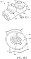
- Figs. 13-1 to 13-2 illustrate a nasal prong assembly 1310 according to another embodiment of the present invention.
- each prong 1330 includes a grate 1370 along an interior portion of the prong 1330, e.g., integrally formed with the prong 1330.
- the grate 1370 is provided at the base of the stalk 1340 of the prong 1330. Also, the grate 1370 is oriented such that the grates 1372 of the grate 1370 extend generally parallel to the minor axis of the prong orifice 1345 (e.g., see Fig. 13-2 ). However, the grate 1370 maybe provided at other suitable locations along the prong, and the grates 1372 may have other suitable shapes and orientations. In addition, the grate 1370 may have any suitable number of grates 1372, e.g., 3, 4, 5, or more grates.
- the grate 1370 increases the dispersion and turbulence of the air as it exits the prong orifice and enters the patient's nasal passage.
- Fig. 14-1 illustrates a nasal prong 1430 including a grate 1470 according to another embodiment of the present invention.
- the grate 1470 is substantially similar to the grate 1370 described above, e.g., grate 1470 is provided at the base of the stalk of the prong 1430.
- the grate 1470 is oriented such that the grates 1472 of the grate 1470 extend generally parallel to the major axis of the prong orifice 1445.
- the grate 1470 may be provided at other suitable locations along the prong, and the grates 1472 may have other suitable shapes and orientations.
- the grate 1470 may have any suitable number of grates 1472, e.g., 3, 4, 5, or more grates.
- the grate 1470 increases the dispersion and turbulence of the air as it exits the prong orifice and enters the patient's nasal passage.
- Fig. 15-1 illustrates a nasal prong 1530 including a grate 1570 according to another embodiment of the present invention.
- the grates 1572 of the grate 1570 have a generally oval or circular configuration, e.g., grates 1572 are curved or arcuate and define one or more generally circular or oval openings through the grate.
- the grate 1570 may be provided at the base of the stalk of the prong 1530, or at other suitable locations along the prong. Also, the grates 1572 may have other suitable shapes and orientations. In addition, the grate 1570 may have any suitable number of grates 1572, e.g., 3, 4, 5, or more grates.
- the grate 1570 increases the dispersion and turbulence of the air as it exits the prong orifice and enters the patient's nasal passage.
- Figs. 16-1 to 16-2 illustrate a nasal prong assembly 1610 according to another embodiment of the present invention.
- each prong 1630 includes a grate 1670 along an interior portion of the prong 1630, e.g., integrally formed with the prong 1630.
- the grate 1670 is provided at the rim of the head portion 1635 of the prong 1630. Also, the grate 1670 is oriented such that the grates 1672 of the grate 1670 extend generally parallel to the minor axis of the prong orifice 1645 (e.g., see
- the grate 1670 may be provided at other suitable locations along the prong, and the grates 1672 may have other suitable shapes and orientations.
- the grate 1670 may have any suitable number of grates 1672, e.g., 3, 4, 5, or more grates.
- the grate 1670 increases the dispersion and turbulence of the air as it exits the prong orifice and enters the patient's nasal passage.
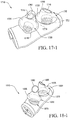
- Fig. 17-1 illustrates a nasal prong assembly 1710 according to another embodiment of the present invention.
- the nasal prong assembly 1710 is a hybrid or combination of the nasal prong assemblies shown in Figs. 4-1 to 4-2 and 13-1 to 13-2 .
- each prong 1730 includes a hood 1760 and a grate 1770, e.g., integrally formed with the prong 1730.
- the hood 1760 is provided to an medial portion (i.e., middle portion) of the head portion 1735 and is structured to re-direct the air flow such that the hood 1760 directs or channels the air flow away from the septum.
- the grate 1770 is provided at the base of the stalk 1740 of the prong 1730. Also, the grate 1770 is oriented such that the grates 1772 of the grate 1770 extend generally parallel to the minor axis of the prong orifice 1745. However, the grate 1770 may be provided at other suitable locations along the prong, and the grates 1772 may have other suitable shapes and orientations. In addition, the grate 1770 may have any suitable number of grates 1772, e.g., 3, 4, 5, or more grates.
- the hood 1760 directs the air posteriorly (e.g., straight up) away from the septum and the grate 1770 increases the dispersion and turbulence of the air as it exits the prong orifice and enters the patient's nasal passage.
- the air flow is both dispersed and channeled away from the septum.
- Fig. 18-1 to 18-2 illustrate a nasal prong assembly 1810 according to another embodiment of the present invention.
- the nasal prong assembly 1810 is a hybrid or combination of the nasal prong assemblies shown in Figs. 5-1 and 13-1 to 13-2 .
- each prong 1830 includes a relatively large hood 1860 and a grate 1870, e.g., integrally formed with the prong 1830.
- the hood 1860 is provided to an medial portion (i.e., middle portion) of the head portion 1835 and is structured to change the air flow such that the hood 1860 directs the air flow away from the septum.
- the grate 1870 is provided at the base of the stalk 1840 of the prong 1830. Also, the grate 1870 is oriented such that the grates 1872 of the grate 1870 extend generally parallel to the minor axis of the prong orifice 1845 (e.g., see Fig. 18-2 ). However, the grate 1870 may be provided at other suitable locations along the prong, and the grates 1872 may have other suitable shapes and orientations. In addition, the grate 1870 may have any suitable number of grates 1872, e.g., 3, 4, 5, or more grates.
- the hood 1860 directs the air posteriorly (e.g., straight up) away from the septum and the grate 1870 increases the dispersion and turbulence of the air as it exits the prong orifice and enters the patient's nasal passage.
- the air flow is both dispersed and away from the septum.
- the hood 1860 may also protect sensitive areas of the anterior nose. 2.6 Dual Wall
- the nasal prong may have a dual or double-wall head portion, i.e., a head portion including an inner wall (inner membrane) and an outer wall (outer membrane) that surrounds the inner wall. Such an arrangement may enhance the comfort and/or seal of the prong.
- Embodiments of dual-wall nasal prongs are disclosed in PCT Appln. Nos. PCT/AU2004/001832 and PCT/AU2006/000770 .
- Fig. 19-1 illustrates a nasal prong assembly 1910 according to a comparative example.
- each prong 1930 includes dual or double-wall head portion 1935.
- each head portion 1935 includes an inner wall 1934 (inner membrane) and an outer wall 1936 (outer membrane) that surrounds the inner wall 1934.
- the outer wall 1936 is relatively thin, e.g., thickness in the range of 0.1 mm to 0.65 mm, and provides compliance and/or conformance with the patient's nose to enhance the seal of the prong 1930.
- the dual-wall nasal prong may be provided in different sizes.
- Fig. 20-1 illustrates a nasal prong assembly 2010 including dual-wall nasal prongs 2030 which are a smaller version of the dual-wall nasal prongs 1930 shown in Fig. 19-1 .
- Such a smaller dual-wall nasal prong 2030 may provide a more comfortable fit and/or seal for some patients.
- Fig. 21-1 illustrates a nasal prong assembly 2110 according to another comparative example.
- each prong 2130 includes dual or double-wall head portion 2135.
- each head portion 2135 includes an inner wall 2134 (inner membrane) and an outer wall 2136 (outer membrane) that surrounds the inner wall 2134.
- the inner wall 2134 includes a plurality of holes 2175.
- the holes 2175 may be provided along any suitable portion of the inner wall 2134.
- the holes 2175 may be circular or may have any other suitable shapes, e.g., non-circular.
- the inner wall 2134 may have any suitable number of holes 2175, e.g., 3, 4, 5, or more holes.
- the holes 2175 disperse air as it passes through the prong 2130, e.g., to create turbulence.
- Figs. 22-1 to 22-2 illustrate a nasal prong assembly 2210 according to an embodiment of the present invention.
- each prong 2230 includes dual or double-wall head portion 2235.
- each prong 2230 includes a grate 2270.
- the grate 2270 is provided at the base of the stalk 2240 of the prong 2230. Also, the grate 2270 is oriented such that the grates 2272 of the grate 2270 extend generally parallel to the minor axis of the prong orifice 2245 (e.g., see Fig. 22-2 ). However, the grate 2270 may be provided at other suitable locations along the prong, and the grates 2272 may have other suitable shapes and orientations. In addition, the grate 2270 may have any suitable number of grates 2272, e.g., 3, 4, 5, or more grates.
- the dual-wall head portion 2235 increases comfort and/or seal and the grate 2270 increases the dispersion and turbulence of the air as it exits the prong orifice and enters the patient's nasal passage.
- Fig. 23-1 illustrates a nasal prong assembly 2310 according to a comparative example.
- each prong 2330 includes dual or double-wall head portion 2335.
- each prong 2330 includes a plurality of ribs 2365 that extend along an interior surface of the outer wall 2336.
- each rib 2365 has a helical shape that extends from the prong orifice to the rib or base of the head portion outer wall 2336.
- the ribs may have other suitable shapes, and may have other suitable arrangements along the outer wall 2336.
- 6 ribs 2365 are provided to each prong 2330.
- each prong 2330 may have any suitable number of ribs, e.g., 3, 4, or 5 ribs.
- ribs may be provided to inner and/or outer surfaces of the inner wall 2334, e.g., in lieu of or in addition to the ribs on the outer wall 2336.
- the dual-wall head portion 2335 increases comfort and/or seal and the helical ribs 2365 introduce swirl to the air flow, which increase the dispersion and turbulence of the air as it exits the prong orifice and enters the patient's nasal passage.
- Figs. 23-2 and 23-3 illustrate a nasal prong 2830 according to another comparative example.
- the prong 2830 includes a dual or double-wall head portion 2835.
- the orifice of the inner wall 2834 includes a series of contours or lobes 2837, e.g., 9 contours or lobes, each having a suitable height H.
- the inner wall 2834 may include any suitable number of contours or lobes, e.g., 3, 4, 5, 6, or more contours or lobes.
- a series of contours or lobes may be provided to the orifice of the outer wall 2836.
- the series of contours or lobes 2837 extend within the plane of the orifice.
- one or more of the contours or lobes may extend in a plane that is transverse to the plane of the orifice.
- the series of contours or lobes 2837 provides a "jet engine like" diffuser or non-oval-shaped orifice which increases the dispersion and turbulence of the air as it exits the orifice and enters the patient's nasal passage.
- Fig. 24-1 illustrates a nasal prong assembly 2410 according to another comparative example.
- each prong 2430 includes dual or double-wall head portion 2435.
- each head portion 2435 includes an inner wall 2434 (inner membrane) and an outer wall 2436 (outer membrane) that surrounds the inner wall 2134.
- the orifice of the inner wall 2434 is substantially lower than the orifice of the outer wall 2436 (e.g., compared to the dual-wall prong shown in Fig. 19-1 ). Such an arrangement may create more diffuse air entering the nasal passage without compromising a seal.
- the dual wall prong may include a hood such as that shown in Figs. 3-1 to 3-3 or 4-1 to 4-2 .
- the hood may extend from the outer wall and/or the inner wall.
- Fig. 25-1 illustrates a nasal prong 2530 according to another comparative example.
- the nasal prong 2530 is provided adjacent to a prong 30 of the old configuration for comparison purposes.
- the prong 2530 includes dual or double-wall head portion 2535 with inner and outer walls 2534, 2536.
- the prong orifice 2545 is shifted more posteriorly and medially (with respect to the prong orifice of the old configuration), e.g., closer to the patient's lip.
- the prong orifice may be shifted to other suitable positions.
- the posteriorly shifted orifice 2545 is structured to shift the air flow more posteriorly and medially as well as direct the air flow more posteriorly and medially, e.g., direct air flow into the nasal passage as opposed to onto the nasal septum.
- the nasal prong 2530 of Fig. 25-1 also includes a hood (e.g., such as that shown in Figs. 3-1 to 3-3 or 4-1 to 4-2 ), and a grate (e.g., such as that shown in Fig. 13-1 ).
- a hood e.g., such as that shown in Figs. 3-1 to 3-3 or 4-1 to 4-2
- a grate e.g., such as that shown in Fig. 13-1 .
- the hood directs the air away from the septum and/or towards the back of the patient's head the grate increases the dispersion and turbulence of the air as it exits the prong orifice and enters the patient's nasal passage.
- a thin wall thickness e.g., thickness in the range of 0.1 mm to 0.65 mm, may be provided to a nasal prong having a single wall configuration. Further details of such thin single wall nasal prong is provided in PCT Appln. No. PCT/AU2006/000770 , for example.
- Ribs may be provided to the thin single wall nasal prong.
- the orifice of the nasal prong may be cut at an angle (with respect to the prong orifice of the old configuration) to direct air flow similar to a hood. That is, the angled orifice changes the air flow direction (with respect to the old configuration) to reduce and/or eliminate the air jetting effect, e.g., direct flow away from the septum.
- Figs. 26-1 to 26-2 illustrate a nasal prong assembly 2610 according to a comparative example.
- each prong 2630 includes a prong orifice 2645 that is cut at about a 45° angle (with respect to the prong orifice of the old configuration).
- the prong orifice 2645 may be cut at other suitable angles, e.g., angle may be dependent on the shape of the patient's nostrils.
- the 45° cut prong orifice 2645 redirects air similar to a hood as described above, and maintains seal, integrity, and comfort. Specifically, as shown in Fig. 26-2 , the 45° cut prong orifice 2645 is structured to direct the air superiorly (as indicated in solid lines), e.g., straight up, rather than towards the septum as in the old configuration (as indicated in dashed lines).
- the nasal prong 2530 of Fig. 25-1 may also include a 45° cut prong orifice (e.g., such as that shown in Figs. 26-1 to 26-2 ).
- the 45° cut prong orifice 2645 directs the air superiorly away from the septum.
- Figs. 27-1 to 27-2 illustrate a nasal prong assembly 2710 according to another comparative example.
- the shape of an anterior portion of the prong 2730 is different than the shape of a posterior portion of the prong 2730.
- the anterior portion of the head portion 2735 has a concave shape or section 2780 (as viewed from the inside of the prong) and the posterior portion of the head portion 2735 has a convex shape or section 2785 (as viewed from the inside of the prong).
- the concave section 2780 of the head portion 2735 directs and disperses the air flow posteriorly, e.g., towards the back of the patient's head.
- a disposable or re-useable gas dispersion cartridge 3090 may be provided to a nasal prong assembly to increase turbulence and/or decrease the velocity in the gas or air flow.
- the dispersion cartridge 3090 includes a plurality of openings that creates turbulence and/or decreases the velocity in the air flow to reduce and/or eliminate the air jetting effect. That is, the dispersion cartridge 3090 disperses the air before it enters the nasal prongs and hence patient's nasal cavity to reduce irritation.
- the dispersion cartridge 3090 is structured to reduce the velocity of air traveling into the nasal passage to provide comfort to the patient (e.g., see sections 2.3 and 2.4.1), reduce noise generated due to air velocity in the mask system, and reduce noise transmitted into the mask system from the flow generator.
- the dispersion cartridge 3090 is a single part that may be provided, e.g., retrofit, to an existing nasal prong assembly (such as that shown in Fig. 1 ).
- the dispersion cartridge 3090 includes a mesh-like cylinder 3092 that provides a plurality of openings or pores 3094 therethrough.
- one end of the mesh-like cylinder 3092 is provided to an end plug 3025, e.g., removably or non-removably attached to the end plug, that is adapted to be attached to one end of the frame 3050. Further details of such end plug are described in the above cited U.S. Patent Application No. 11,101,657 .
- the mesh-like cylinder 3092 extends through the proximal side frame member 3052 and towards the opposite side frame member 3052 of the frame 3050. Also, the distal end of the mesh-like cylinder 3092 extends towards the elbow 3027 attached to the opposite end of the frame 3050 and communicated with the air delivery tube. The distal end may engage with an interior surface of the opposite side frame member, e.g., an interference or friction fit. Similarly, the proximal end of the mesh-like cylinder 3092 may frictionally engage with an interior surface of the end plug 3025.
- a nasal prong assembly 3010 (including a base 3020 and a pair of nasal prongs 3030) is attached to the frame 3050 as shown in Fig. 28-3 , the mesh-like cylinder 3092 extends through the base 3020 and across the inlets to the nasal prongs 3030.
- gas enters through the elbow 3027 and is directed through the mesh-like cylinder 3092 to disperse or dissipate the gas before it enters the nasal prongs 3030 and hence the patient's nasal cavity to reduce irritation.
- the large surface area of the mesh-like cylinder 3092 prevents any additional impedance to the air delivery circuit.
- the end plug 3025 maybe easily removed from the frame 3050 to clean and/or replace the mesh-like cylinder 3092 attached thereto.
- the mesh-like cylinder 3092 may be washed and reused, or the mesh-like cylinder 3092 may be made as a disposable item.
- the positions of the end plug 3025 and elbow 3027 may be interchanged, according to preference.
- the mesh-like cylinder 3092 may be attached to the elbow 3027 or opposite side frame member 3052 instead of the end plug 3025.
- the mesh-like cylinder 3092 may be supported by the side frame members 3052 of the frame 3050, and sandwiched between the elbow 3027 and the end plug 3025 to secure the mesh-like cylinder 3092 in place.
- the mesh-like cylinder 3092 may be made of a metal or plastic mesh material.
- the mesh-like cylinder 3092 may be made of a fabric or textile material that is gas permeable, e.g., Gortex®.
- a dispersion cartridge 3190 may include a thin-wall plastic or ceramic cylinder 3192 with a plurality of perforated holes 3194 therethrough.
- the cylinder 3192 may include 1-600 holes or more, e.g., 1-30 rows each having 1-20 holes. In the example shown, the cylinder has 20-25 rows each having 15-20 holes. The holes could be patterned so as to avoid direct jetting into the nasal prongs.
- the dispersion cartridge 3092 has a cylindrical shape.
- the dispersion cartridge 3092 may have other suitable shapes to fit within the nasal prong assembly, e.g., flat or planar shape.
- a dispersion cartridge may comprise a flat piece of material, e.g., mesh-like material, which is rolled into cylindrical form and then inserted into the frame, elbow, and/or end plug.
- the dispersion cartridge 3092 may provide additional uses.
- the dispersion cartridge 3092 may also be used as a medicine/aromatic dispenser, moisture absorber, and/or humidifying element.
- medicine may be provided within the dispersion cartridge and adapted to be dispersed as air passes through the dispersion cartridge.
- the cartridge may be provided with a filtering function. The filtering can occur as a result of the perforations and/or hole size, or the filtering can be provided by a separate component, such as a filter.
Claims (15)
- Nasenzapfen bzw. Nasalprong (240, 340, 440, 540, 640, 740, 840, 940, 1040, 1140, 1240,1340, 1440, 1540, 1640, 1740, 1840, 1940, 2040, 2140, 2240, 2340, 2440, 2540, 2640, 2740, 2840) zum Abdichten mit einem Nasengang eines Patienten zur Verabreichung einer Atemtherapie zur Behandlung einer schlafbezogenen Atmungsstörung, die aufweist:einen Kopfabschnitt (235, 335, 435, 535, 635, 735, 835, 935, 1035, 1635, 1735, 1835, 1935, 2135, 2235, 2335, 2435, 2535, 2735, 2835), der strukturiert ist, mit dem Nasengang des Patienten abzudichten und/oder abdichtend in Verbindung zu stehen; undeine Säule oder ein Stängel (1040, 1340, 1740, 1840, 2240), der strukturiert ist, den Kopfabschnitt mit einer Basis zu verbinden,dadurch gekennzeichnet, dassder Kopfabschnitt ein Gitter (1370, 1470, 1570, 1670, 1770, 1870, 2270) aufweist, das strukturiert ist, einen Luftstrom zu zerstreuen und/oder eine Turbulenz im Luftstrom zu erzeugen, bevor er in die Nasenhöhle des Patienten eintritt, um Luftstrahlbildungseffekte zu reduzieren und/oder zu beseitigen.
- Nasenzapfen bzw. Nasalprong nach Anspruch 1, wobei der Kopfabschnitt eine Haube (260, 360, 460, 1760, 1860) aufweist, die strukturiert ist, die Luftstromrichtung zu ändern, um Luftstrahlbildungseffekte zu reduzieren und/oder zu beseitigen.
- Nasenzapfen bzw. Nasalprong nach Anspruch 2, wobei die Haube eine Oberflächenbehandlung aufweist.
- Nasenzapfen bzw. Nasalprong nach Anspruch 2, wobei die Haube strukturiert ist, im Gebrauch Gas von der Nasenscheidewand weg und/oder relativ zum Nasengang posterior zu richten.
- Nasenzapfen bzw. Nasalprong nach Anspruch 2, wobei die Haube an einem anterioren Abschnitt des Kopfabschnitts vorgesehen und strukturiert ist, im Gebrauch den Luftstrom von der Nasenscheidewand des Patienten weg und in Richtung des Hinterkopfs des Patienten zu richten.
- Nasenzapfen bzw. Nasalprong nach Anspruch 2, wobei die Haube an einem medialen Abschnitt des Kopfabschnitts vorgesehen und strukturiert ist, im Gebrauch den Luftstrom von der Nasenscheidewand des Patienten weg zu richten.
- Nasenzapfen bzw. Nasalprong nach Anspruch 5 oder 6, wobei die Haube integral mit dem Kopfabschnitt ausgebildet ist.
- Nasenzapfen bzw. Nasalprong nach Anspruch 1, wobei das Gitter eine Oberflächenbehandlung aufweist.
- Nasenzapfen bzw. Nasalprong nach Anspruch 1, wobei das Gitter an einer Basis des Stängels vorgesehen ist.
- Nasenzapfen bzw. Nasalprong nach Anspruch 1, wobei das Gitter an einem Rand des Kopfabschnitts vorgesehen ist.
- Nasenzapfen bzw. Nasalprong nach Anspruch 1, wobei der Kopfabschnitt eine Austrittsöffnung (545, 645, 745, 1145, 1245, 1345, 1445, 1645, 1745, 1845, 2245, 2545, 2645) aufweist, die von einer Achse des Stängels versetzt ist.
- Nasenzapfen bzw. Nasalprong (240, 340, 440, 540, 640, 740, 840, 940, 1040, 1140, 1240,1340, 1440, 1540, 1640, 1740, 1840, 1940, 2040, 2140, 2240, 2340, 2440, 2540, 2640, 2740, 2840) zum Abdichten mit einem Nasengang eines Patienten zur Verabreichung einer Atemtherapie zur Behandlung einer schlafbezogenen Atmungsstörung, die aufweist:einen Kopfabschnitt (235, 335, 435, 535, 635, 735, 835, 935, 1035, 1635, 1735, 1835, 1935, 2135, 2235, 2335, 2435, 2535, 2735, 2835), der strukturiert ist, mit dem Nasengang des Patienten abzudichten und/oder abdichtend in Verbindung zu stehen; undeine Säule oder einen Stängel (1040, 1340, 1740, 1840, 2240), der strukturiert ist, den Kopfabschnitt mit einer Basis zu verbinden,dadurch gekennzeichnet, dassder Kopfabschnitt eine Austrittsöffnung aufweist, die eine dreieckige Form aufweist, so dass der Luftstrom nicht auf empfindliche Regionen der Nase des Patienten gerichtet wird.
- Nasenzapfen bzw. Nasalprong nach Anspruch 12, wobei die Austrittsöffnung (545, 645, 745, 1145, 1245, 1345, 1445, 1645, 1745, 1845, 2245, 2545, 2645) von einer Achse des Stängels versetzt ist.
- Nasenzapfen bzw. Nasalprong nach Anspruch 11 oder 13, wobei die Austrittsöffnung im Gebrauch posterior verschoben ist, um Gas relativ zum Nasengang posterior zu richten.
- Nasenzapfenanordnung bzw. Nasalpronganordnung, die aufweist: eine Basis; und
ein Paar Nasenzapfen bzw. Nasalprongs nach Anspruch 1 oder 12, die an der Basis vorgesehen sind.
Applications Claiming Priority (3)
| Application Number | Priority Date | Filing Date | Title |
|---|---|---|---|
| US83544206P | 2006-08-04 | 2006-08-04 | |
| US85264906P | 2006-10-19 | 2006-10-19 | |
| PCT/AU2007/001060 WO2008014543A1 (en) | 2006-08-04 | 2007-07-30 | Nasal prongs for mask system |
Publications (3)
| Publication Number | Publication Date |
|---|---|
| EP2051761A1 EP2051761A1 (de) | 2009-04-29 |
| EP2051761A4 EP2051761A4 (de) | 2014-01-08 |
| EP2051761B1 true EP2051761B1 (de) | 2019-08-21 |
Family
ID=38996772
Family Applications (1)
| Application Number | Title | Priority Date | Filing Date |
|---|---|---|---|
| EP07784705.1A Active EP2051761B1 (de) | 2006-08-04 | 2007-07-30 | Nasengabel für ein maskensystem |
Country Status (3)
| Country | Link |
|---|---|
| US (3) | US9943660B2 (de) |
| EP (1) | EP2051761B1 (de) |
| WO (1) | WO2008014543A1 (de) |
Families Citing this family (88)
| Publication number | Priority date | Publication date | Assignee | Title |
|---|---|---|---|---|
| US7588033B2 (en) | 2003-06-18 | 2009-09-15 | Breathe Technologies, Inc. | Methods, systems and devices for improving ventilation in a lung area |
| EP1660004A4 (de) | 2003-08-18 | 2017-05-31 | Breathe Technologies, Inc. | Verfahren und vorrichtung für die nichtinvasive ventilation mit nasaler schnittstelle |
| US8783257B2 (en) | 2004-02-23 | 2014-07-22 | Fisher & Paykel Healthcare Limited | Breathing assistance apparatus |
| WO2005094928A1 (en) | 2004-04-02 | 2005-10-13 | Fisher & Paykel Healthcare Limited | Breathing assistance apparatus |
| EP1926517A2 (de) | 2005-09-20 | 2008-06-04 | Lutz Freitag | Systeme, verfahren und gerät zur atemunterstützung eines patienten |
| USD587800S1 (en) * | 2006-04-14 | 2009-03-03 | Resmed Limited | Respiratory mask cushion frame |
| USD623288S1 (en) * | 2006-04-28 | 2010-09-07 | Resmed Limited | Patient interface |
| CN101541365A (zh) | 2006-05-18 | 2009-09-23 | 呼吸科技公司 | 气管切开方法和装置 |
| GB0610171D0 (en) | 2006-05-23 | 2006-06-28 | Robitaille Jean Pierre | Valved nasal canula |
| CA2890556C (en) | 2006-07-14 | 2018-05-01 | Fisher & Paykel Healthcare Limited | Breathing assistance apparatus |
| JP2009545384A (ja) | 2006-08-03 | 2009-12-24 | ブリーズ テクノロジーズ, インコーポレイテッド | 最小侵襲性呼吸補助のための方法および装置 |
| WO2008014543A1 (en) | 2006-08-04 | 2008-02-07 | Resmed Ltd | Nasal prongs for mask system |
| WO2008144589A1 (en) | 2007-05-18 | 2008-11-27 | Breathe Technologies, Inc. | Methods and devices for sensing respiration and providing ventilation therapy |
| NZ754622A (en) * | 2007-07-30 | 2021-02-26 | ResMed Pty Ltd | Patient interface |
| CA2700878C (en) | 2007-09-26 | 2018-07-24 | Breathe Technologies, Inc. | Methods and devices for providing inspiratory and expiratory flow relief during ventilation therapy |
| CN101888868B (zh) | 2007-09-26 | 2014-01-22 | 呼吸科技公司 | 用于治疗睡眠呼吸暂停的方法和设备 |
| WO2011014931A1 (en) | 2009-08-07 | 2011-02-10 | Resmed Ltd | Patient interface systems |
| USD656231S1 (en) | 2009-04-20 | 2012-03-20 | Resmed Limited | Respiratory mask |
| US8573201B2 (en) | 2007-10-22 | 2013-11-05 | Resmed Limited | Patient interface systems |
| USD637279S1 (en) | 2008-01-11 | 2011-05-03 | Resmed Limited | Strap and yoke for mask |
| DE102008010475A1 (de) * | 2008-02-21 | 2009-08-27 | Seleon Gmbh | Applikatoren für eine Luftbrille |
| US8776793B2 (en) | 2008-04-18 | 2014-07-15 | Breathe Technologies, Inc. | Methods and devices for sensing respiration and controlling ventilator functions |
| EP2274036A4 (de) | 2008-04-18 | 2014-08-13 | Breathe Technologies Inc | Verfahren und vorrichtungen zur messung von atmung und zur kontrolle der funktionen eines beatmungsgeräts |
| EP2113274B1 (de) * | 2008-04-30 | 2016-04-27 | ResMed R&D Germany GmbH | Vorrichtung zur gesteuerten Zufuhr eines Atemgases an die Atemwege eines Benutzers |
| US10792451B2 (en) | 2008-05-12 | 2020-10-06 | Fisher & Paykel Healthcare Limited | Patient interface and aspects thereof |
| US10258757B2 (en) | 2008-05-12 | 2019-04-16 | Fisher & Paykel Healthcare Limited | Patient interface and aspects thereof |
| US8905031B2 (en) | 2008-06-04 | 2014-12-09 | Resmed Limited | Patient interface systems |
| CN106039505A (zh) | 2008-06-04 | 2016-10-26 | 瑞思迈有限公司 | 患者接口系统 |
| NZ776389A (en) * | 2008-06-05 | 2023-02-24 | ResMed Pty Ltd | Treatment of respiratory conditions |
| WO2009151344A1 (en) * | 2008-06-12 | 2009-12-17 | Fisher & Paykel Healthcare Limited | Respiratory nasal interface with sealing cap portions |
| TW201002379A (en) * | 2008-07-01 | 2010-01-16 | Galemed Corp | Auxiliary tool for babyaerosol and oxygen therapy |
| US11660413B2 (en) | 2008-07-18 | 2023-05-30 | Fisher & Paykel Healthcare Limited | Breathing assistance apparatus |
| US8677999B2 (en) | 2008-08-22 | 2014-03-25 | Breathe Technologies, Inc. | Methods and devices for providing mechanical ventilation with an open airway interface |
| CA2739435A1 (en) | 2008-10-01 | 2010-04-08 | Breathe Technologies, Inc. | Ventilator with biofeedback monitoring and control for improving patient activity and health |
| WO2010041966A1 (en) | 2008-10-10 | 2010-04-15 | Fisher & Paykel Healthcare Limited | Nasal pillows for a patient interface |
| DE102009047246A1 (de) | 2008-12-01 | 2010-06-10 | Fisher & Paykel Healthcare Ltd., East Tamaki | Nasenkanüle |
| US9132250B2 (en) | 2009-09-03 | 2015-09-15 | Breathe Technologies, Inc. | Methods, systems and devices for non-invasive ventilation including a non-sealing ventilation interface with an entrainment port and/or pressure feature |
| CA2757591C (en) | 2009-04-02 | 2021-01-05 | Breathe Technologies, Inc. | Methods, systems and devices for non-invasive open ventilation with gas delivery nozzles within an outer tube |
| US9962512B2 (en) | 2009-04-02 | 2018-05-08 | Breathe Technologies, Inc. | Methods, systems and devices for non-invasive ventilation including a non-sealing ventilation interface with a free space nozzle feature |
| US20100326441A1 (en) * | 2009-06-24 | 2010-12-30 | Shlomo Zucker | Nasal interface device |
| CA2774902C (en) | 2009-09-03 | 2017-01-03 | Breathe Technologies, Inc. | Methods, systems and devices for non-invasive ventilation including a non-sealing ventilation interface with an entrainment port and/or pressure feature |
| US10137271B2 (en) | 2009-11-18 | 2018-11-27 | Fisher & Paykel Healthcare Limited | Nasal interface |
| US20120318271A1 (en) * | 2010-01-15 | 2012-12-20 | Koninklijke Philips Electronics N.V. | Replaceable nasal pillow kit |
| CN102725018A (zh) * | 2010-01-15 | 2012-10-10 | 皇家飞利浦电子股份有限公司 | 可更换的鼻枕 |
| FR2958168B1 (fr) * | 2010-03-31 | 2012-05-18 | Georges Boussignac | Sonde nasale |
| FR2958169B1 (fr) * | 2010-03-31 | 2012-12-21 | Georges Boussignac | Sonde nasale |
| US11628267B2 (en) | 2010-08-04 | 2023-04-18 | Medline Industries, Lp | Universal medical gas delivery system |
| US9199052B2 (en) * | 2010-08-04 | 2015-12-01 | Darren Rubin | Universal medical gas delivery system |
| CA2807416C (en) | 2010-08-16 | 2019-02-19 | Breathe Technologies, Inc. | Methods, systems and devices using lox to provide ventilatory support |
| USD691257S1 (en) * | 2010-08-23 | 2013-10-08 | Fisher & Paykel Healthcare Limited | Seal for a patient interface |
| WO2012045051A1 (en) | 2010-09-30 | 2012-04-05 | Breathe Technologies, Inc. | Methods, systems and devices for humidifying a respiratory tract |
| US9561338B2 (en) | 2010-10-08 | 2017-02-07 | Fisher & Paykel Healthcare Limited | Breathing assistance apparatus |
| CN107773825A (zh) * | 2010-10-18 | 2018-03-09 | 费雪派克医疗保健有限公司 | 鼻插管、导管和固定系统 |
| USD692554S1 (en) | 2011-09-08 | 2013-10-29 | Fisher & Paykel Healthcare Limited | Patient interface assembly |
| US9730830B2 (en) | 2011-09-29 | 2017-08-15 | Trudell Medical International | Nasal insert and cannula and methods for the use thereof |
| BR112014020260A8 (pt) * | 2012-02-16 | 2017-07-11 | Capnia Inc | Distribuidor de gás com peça nasal de difusão |
| EP2679266B1 (de) | 2012-06-29 | 2016-06-08 | Air Liquide Medical Systems | Kopplungssystem zur Sicherung eines Nasenkissens an einer Atemmaske |
| EP2679267A1 (de) | 2012-06-29 | 2014-01-01 | Air Liquide Medical Systems | Nasenkissen mit schwenkbaren Haken für eine nasale Atemmaske |
| US9468732B2 (en) * | 2012-07-31 | 2016-10-18 | Inovo, Inc. | Fluidic-controlled reservoir cannula |
| CN107626023B (zh) | 2012-08-08 | 2021-03-02 | 费雪派克医疗保健有限公司 | 在提供呼吸治疗中使用的接口组件 |
| CN104780965B (zh) * | 2012-09-12 | 2017-03-08 | 斯沃博发展有限责任公司 | 用于与呼吸辅助装置一起使用的鼻接口设备和系统 |
| US11904096B2 (en) | 2012-09-12 | 2024-02-20 | Inogen, Inc. | Nasal interface apparatus and systems for use with a respiratory assist device |
| JP6479675B2 (ja) * | 2012-12-11 | 2019-03-06 | コーニンクレッカ フィリップス エヌ ヴェKoninklijke Philips N.V. | 鼻カニューレシステム及び方法 |
| WO2014097083A1 (en) * | 2012-12-18 | 2014-06-26 | Koninklijke Philips N.V. | Diffusion device for a nasal cushion apparatus |
| US9878121B2 (en) * | 2013-03-13 | 2018-01-30 | Breathe Technologies, Inc. | Ventilation mask with heat and moisture exchange device |
| CN109675166B (zh) * | 2013-03-15 | 2022-07-01 | 费雪派克医疗保健有限公司 | 鼻套管组件和相关部件 |
| US10569043B2 (en) | 2013-08-09 | 2020-02-25 | Fisher & Paykel Healthcare Limited | Asymmetrical nasal delivery elements and fittings for nasal interfaces |
| US10933210B2 (en) * | 2013-09-23 | 2021-03-02 | Fisher & Paykel Healthcare Limited | Nasal cannula with turbulation elements |
| USD770608S1 (en) * | 2013-11-08 | 2016-11-01 | Silverbow Development Llc | Interface for mechanical ventilation |
| NZ725586A (en) * | 2014-04-23 | 2018-04-27 | Resmed Ltd | Device for retaining humidity in a patient interface |
| NZ630742A (en) | 2014-05-01 | 2016-02-26 | Resmed Ltd | A patient interface |
| NZ780711A (en) * | 2014-06-19 | 2023-03-31 | ResMed Pty Ltd | Patient interface for respiratory therapy |
| CN110152153B (zh) * | 2014-07-16 | 2021-11-23 | 人类设计医疗有限公司 | 用于与通气和正空气压系统一起使用的面部接口和头套系统 |
| EP3200857B1 (de) | 2014-10-03 | 2021-01-13 | AUT University | Verfahren und vorrichtung für die kontrollierte freisetzung von gasen |
| JP6875797B2 (ja) * | 2016-06-14 | 2021-05-26 | 日本光電工業株式会社 | ガスセンサキット及び顔面装着具 |
| US10960163B2 (en) * | 2016-09-02 | 2021-03-30 | Fresca Medical Inc. | Apparatus, systems, and methods for improved treatment of obstructive sleep apnea |
| USD870269S1 (en) | 2016-09-14 | 2019-12-17 | Fisher & Paykel Healthcare Limited | Nasal cannula assembly |
| USD848605S1 (en) * | 2016-12-05 | 2019-05-14 | Koninklijke Philips N.V. | Cushion |
| US20180344961A1 (en) * | 2017-06-01 | 2018-12-06 | Ronald J. Thompson | Vortex air flow and nasal cpap |
| US10792449B2 (en) | 2017-10-03 | 2020-10-06 | Breathe Technologies, Inc. | Patient interface with integrated jet pump |
| USD849243S1 (en) | 2017-11-21 | 2019-05-21 | Fisher & Paykel Healthcare Limited | Nasal cannula |
| USD849242S1 (en) | 2017-11-21 | 2019-05-21 | Fisher & Paykel Healthcare Limited | Nasal cannula assembly |
| USD878549S1 (en) | 2017-11-21 | 2020-03-17 | Fisher & Paykel Healthcare Limited | Connector for nasal cannula assembly |
| USD848614S1 (en) | 2017-11-21 | 2019-05-14 | Fisher & Paykel Healthcare Limited | Pad for nasal cannula assembly |
| TWI657838B (zh) * | 2018-04-03 | 2019-05-01 | 貝斯美德股份有限公司 | 具有滑軌機構的鼻導管 |
| JP1712959S (ja) * | 2020-06-16 | 2022-04-19 | 鼻マスク用クッション | |
| US20220401683A1 (en) * | 2021-06-14 | 2022-12-22 | Ari Namon | Airflow nasal prong |
| USD975842S1 (en) * | 2022-02-21 | 2023-01-17 | Tumba Dental AB | Part of a breathing mask |
Citations (11)
| Publication number | Priority date | Publication date | Assignee | Title |
|---|---|---|---|---|
| JPS61276566A (ja) * | 1985-05-30 | 1986-12-06 | 帝人株式会社 | 鼻カニユ−ラ及びそれを用いた酸素富化装置 |
| US4782832A (en) * | 1987-07-30 | 1988-11-08 | Puritan-Bennett Corporation | Nasal puff with adjustable sealing means |
| WO1999058181A1 (en) * | 1998-05-14 | 1999-11-18 | Joseph Goldstein | Nasal air delivery apparatus |
| US6342040B1 (en) * | 1998-02-25 | 2002-01-29 | Respironics, Inc. | Patient monitor and method of using same |
| US6478026B1 (en) * | 1999-03-13 | 2002-11-12 | Thomas J. Wood | Nasal ventilation interface |
| US20030094178A1 (en) * | 2001-11-16 | 2003-05-22 | Mcauley Alastair Edwin | Nasal positive pressure device |
| WO2004073778A1 (en) * | 2003-02-21 | 2004-09-02 | Resmed Limited | Nasal assembly |
| US20050039757A1 (en) * | 1999-03-13 | 2005-02-24 | Wood Thomas J. | Ventilation interface for sleep apnea therapy |
| WO2005018524A2 (en) * | 2003-08-18 | 2005-03-03 | Wondka Anthony D | Method and device for non-invasive ventilation with nasal interface |
| WO2005079726A1 (en) * | 2004-02-23 | 2005-09-01 | Fisher & Paykel Healthcare Limited | Breathing assistance apparatus |
| WO2006024253A1 (de) * | 2004-09-03 | 2006-03-09 | Weinmann Geräte für Medizin GmbH & Co. KG | Kunststoffe für medizintechnische geräte |
Family Cites Families (35)
| Publication number | Priority date | Publication date | Assignee | Title |
|---|---|---|---|---|
| US2535155A (en) * | 1947-11-28 | 1950-12-26 | Victor H Pandorf | Nasal filter |
| US2604094A (en) * | 1949-06-25 | 1952-07-22 | Schenley Ind Inc | Inhaler |
| US3400714A (en) * | 1965-05-03 | 1968-09-10 | Brunswick Corp | Nasal cannula |
| US3905335A (en) * | 1974-03-21 | 1975-09-16 | Gerald J Kapp | Nasal air filter |
| US4052983A (en) * | 1975-09-04 | 1977-10-11 | Bovender Coy R | Nasal filter |
| US4708446A (en) | 1985-12-13 | 1987-11-24 | Engineered Specialty Products | Eyeglass frame and nasal cannula assembly |
| SE453566B (sv) * | 1986-03-07 | 1988-02-15 | Draco Ab | Anordning vid pulverinhalatorer |
| US5099836A (en) * | 1987-10-05 | 1992-03-31 | Hudson Respiratory Care Inc. | Intermittent oxygen delivery system and cannula |
| US4907584A (en) * | 1988-03-03 | 1990-03-13 | Mcginnis Gerald E | Respiratory mask |
| US4919128A (en) | 1988-08-26 | 1990-04-24 | University Technologies International Inc. | Nasal adaptor device and seal |
| US5724965A (en) * | 1995-06-06 | 1998-03-10 | Respironics Inc. | Nasal mask |
| US6439230B1 (en) * | 1999-06-18 | 2002-08-27 | Resmed Limited | Mask with recess including at least one mask port |
| US7059328B2 (en) * | 2000-03-13 | 2006-06-13 | Innomed Technologies, Inc. | Ventilation interface for sleep apnea therapy |
| US20060150982A1 (en) | 2003-08-05 | 2006-07-13 | Wood Thomas J | Nasal ventilation interface and system |
| US6561188B1 (en) * | 2000-08-21 | 2003-05-13 | Ellis Alan D | Nasal breathing apparatus and methods |
| US6668828B1 (en) * | 2000-10-16 | 2003-12-30 | Pulmonox Technologies Corporations | System and elements for managing therapeutic gas administration to a spontaneously breathing non-ventilated patient |
| US7832400B2 (en) * | 2001-01-04 | 2010-11-16 | Salter Labs | Nasal and oral cannula having two capabilities and method of producing same |
| DE10105383C2 (de) * | 2001-02-06 | 2003-06-05 | Heptec Gmbh | Antischnarchgerät |
| EP1450885B1 (de) * | 2001-09-28 | 2015-04-22 | Kurve Technology, Inc. | Nasaler vernebler |
| US6815049B2 (en) | 2001-12-11 | 2004-11-09 | United States Gypsum Company | Gypsum-containing composition having enhanced resistance to permanent deformation |
| AU2004202274B2 (en) | 2003-05-30 | 2006-10-26 | Fisher & Paykel Healthcare Limited | Breathing Assistance Apparatus |
| US20050011524A1 (en) * | 2003-07-17 | 2005-01-20 | Marguerite Thomlinson | Nasal interface apparatus |
| US7191781B2 (en) | 2003-08-05 | 2007-03-20 | Innomed Technologies, Inc. | Nasal ventilation interface and system |
| US6997187B2 (en) * | 2003-09-10 | 2006-02-14 | Innomed Technologies, Inc. | Nasal interface and system including ventilation insert |
| US7353826B2 (en) * | 2003-08-08 | 2008-04-08 | Cardinal Health 205, Inc. | Sealing nasal cannula |
| NZ732925A (en) * | 2003-12-31 | 2019-01-25 | ResMed Pty Ltd | Compact oronasal patient interface |
| US7178525B2 (en) | 2004-02-06 | 2007-02-20 | Ric Investments, Llc | Patient interface assembly supported under the mandible |
| NZ550348A (en) | 2004-04-09 | 2011-02-25 | Resmed Ltd | Nasal assembly with vent and baffle |
| USD533269S1 (en) * | 2004-08-19 | 2006-12-05 | Fisher & Paykel Healthcare Limited | Nasal cannula |
| US20060107958A1 (en) * | 2004-11-22 | 2006-05-25 | Sleeper Geoffrey P | Adjustable sealing nasal cannula |
| AU2006255476B2 (en) * | 2005-06-06 | 2012-07-05 | ResMed Pty Ltd | Mask system |
| US20090151729A1 (en) * | 2005-11-08 | 2009-06-18 | Resmed Limited | Nasal Assembly |
| AU2006202519A1 (en) | 2006-05-31 | 2006-07-27 | Grant Stafford | Poims |
| CA2890556C (en) | 2006-07-14 | 2018-05-01 | Fisher & Paykel Healthcare Limited | Breathing assistance apparatus |
| WO2008014543A1 (en) | 2006-08-04 | 2008-02-07 | Resmed Ltd | Nasal prongs for mask system |
-
2007
- 2007-07-30 WO PCT/AU2007/001060 patent/WO2008014543A1/en active Application Filing
- 2007-07-30 EP EP07784705.1A patent/EP2051761B1/de active Active
- 2007-07-30 US US12/309,917 patent/US9943660B2/en active Active
-
2018
- 2018-03-28 US US15/938,152 patent/US11517698B2/en active Active
-
2022
- 2022-10-19 US US18/047,892 patent/US20230082745A1/en not_active Abandoned
Patent Citations (11)
| Publication number | Priority date | Publication date | Assignee | Title |
|---|---|---|---|---|
| JPS61276566A (ja) * | 1985-05-30 | 1986-12-06 | 帝人株式会社 | 鼻カニユ−ラ及びそれを用いた酸素富化装置 |
| US4782832A (en) * | 1987-07-30 | 1988-11-08 | Puritan-Bennett Corporation | Nasal puff with adjustable sealing means |
| US6342040B1 (en) * | 1998-02-25 | 2002-01-29 | Respironics, Inc. | Patient monitor and method of using same |
| WO1999058181A1 (en) * | 1998-05-14 | 1999-11-18 | Joseph Goldstein | Nasal air delivery apparatus |
| US6478026B1 (en) * | 1999-03-13 | 2002-11-12 | Thomas J. Wood | Nasal ventilation interface |
| US20050039757A1 (en) * | 1999-03-13 | 2005-02-24 | Wood Thomas J. | Ventilation interface for sleep apnea therapy |
| US20030094178A1 (en) * | 2001-11-16 | 2003-05-22 | Mcauley Alastair Edwin | Nasal positive pressure device |
| WO2004073778A1 (en) * | 2003-02-21 | 2004-09-02 | Resmed Limited | Nasal assembly |
| WO2005018524A2 (en) * | 2003-08-18 | 2005-03-03 | Wondka Anthony D | Method and device for non-invasive ventilation with nasal interface |
| WO2005079726A1 (en) * | 2004-02-23 | 2005-09-01 | Fisher & Paykel Healthcare Limited | Breathing assistance apparatus |
| WO2006024253A1 (de) * | 2004-09-03 | 2006-03-09 | Weinmann Geräte für Medizin GmbH & Co. KG | Kunststoffe für medizintechnische geräte |
Also Published As
| Publication number | Publication date |
|---|---|
| US20230082745A1 (en) | 2023-03-16 |
| US11517698B2 (en) | 2022-12-06 |
| US20090320851A1 (en) | 2009-12-31 |
| WO2008014543A1 (en) | 2008-02-07 |
| EP2051761A4 (de) | 2014-01-08 |
| US9943660B2 (en) | 2018-04-17 |
| EP2051761A1 (de) | 2009-04-29 |
| US20180214653A1 (en) | 2018-08-02 |
Similar Documents
| Publication | Publication Date | Title |
|---|---|---|
| US20230082745A1 (en) | Nasal prongs for mask system | |
| US9539405B2 (en) | Breathing assistance apparatus | |
| US9878121B2 (en) | Ventilation mask with heat and moisture exchange device | |
| US8602025B2 (en) | Apparatus and methods for providing humidity in respiratory therapy | |
| JP6351263B2 (ja) | マスク通気口 | |
| US7234465B2 (en) | Nasal ventilation interface and system | |
| US20170296770A1 (en) | Connector for a respiratory mask and a respiratory mask | |
| CA2556016C (en) | Sealing nasal cannula | |
| EP2112937B1 (de) | Nasenmaske | |
| EP3515541B1 (de) | Entlüftung und entlüftungsadapter für patientenschnittstelle | |
| CA2998247A1 (en) | Breathing assistance apparatus with support member | |
| AU2017358062B2 (en) | Gas washout vent for patient interface | |
| JP2008526394A (ja) | ガス逃がし通気孔を有する呼吸マスクおよびマスクの製造方法 | |
| EP4098306A1 (de) | Entlüftungen für patientenschnittstellen | |
| CN110944704B (zh) | 呼吸用户接口 | |
| CN116322851A (zh) | 用于患者接口设备的排气装置和包括该装置的患者接口 | |
| AU2023100018A4 (en) | Patient interface | |
| EP4137187A1 (de) | Entlüftungsstruktur für ein atemtherapiesystem | |
| KR20240010716A (ko) | 환자 인터페이스 | |
| AU2015201920B2 (en) | Breathing assistance apparatus | |
| WO2023067558A1 (en) | Patient interface | |
| AU2007202555A1 (en) | Respiratory Mask Having Gas Washout Vent and Gas Washout Vent Assembly for a Respiratory Mask |
Legal Events
| Date | Code | Title | Description |
|---|---|---|---|
| PUAI | Public reference made under article 153(3) epc to a published international application that has entered the european phase |
Free format text: ORIGINAL CODE: 0009012 |
|
| 17P | Request for examination filed |
Effective date: 20090225 |
|
| AK | Designated contracting states |
Kind code of ref document: A1 Designated state(s): AT BE BG CH CY CZ DE DK EE ES FI FR GB GR HU IE IS IT LI LT LU LV MC MT NL PL PT RO SE SI SK TR |
|
| AX | Request for extension of the european patent |
Extension state: AL BA HR MK RS |
|
| RIN1 | Information on inventor provided before grant (corrected) |
Inventor name: GALE, DAVID, RAE Inventor name: HITCHCOCK, ROBIN, GARTH Inventor name: DANTANARAYANA, MUDITHA, PRADEEP Inventor name: SELVARAJAN, KARTHIKEYAN |
|
| DAX | Request for extension of the european patent (deleted) | ||
| A4 | Supplementary search report drawn up and despatched |
Effective date: 20131205 |
|
| RIC1 | Information provided on ipc code assigned before grant |
Ipc: A61M 15/08 20060101ALI20131129BHEP Ipc: A62B 7/00 20060101ALI20131129BHEP Ipc: A61M 16/06 20060101AFI20131129BHEP |
|
| STAA | Information on the status of an ep patent application or granted ep patent |
Free format text: STATUS: EXAMINATION IS IN PROGRESS |
|
| 17Q | First examination report despatched |
Effective date: 20170412 |
|
| GRAP | Despatch of communication of intention to grant a patent |
Free format text: ORIGINAL CODE: EPIDOSNIGR1 |
|
| STAA | Information on the status of an ep patent application or granted ep patent |
Free format text: STATUS: GRANT OF PATENT IS INTENDED |
|
| RIC1 | Information provided on ipc code assigned before grant |
Ipc: A61M 16/06 20060101AFI20190109BHEP |
|
| INTG | Intention to grant announced |
Effective date: 20190206 |
|
| GRAS | Grant fee paid |
Free format text: ORIGINAL CODE: EPIDOSNIGR3 |
|
| RAP1 | Party data changed (applicant data changed or rights of an application transferred) |
Owner name: RESMED PTY LTD |
|
| GRAA | (expected) grant |
Free format text: ORIGINAL CODE: 0009210 |
|
| STAA | Information on the status of an ep patent application or granted ep patent |
Free format text: STATUS: THE PATENT HAS BEEN GRANTED |
|
| AK | Designated contracting states |
Kind code of ref document: B1 Designated state(s): AT BE BG CH CY CZ DE DK EE ES FI FR GB GR HU IE IS IT LI LT LU LV MC MT NL PL PT RO SE SI SK TR |
|
| REG | Reference to a national code |
Ref country code: GB Ref legal event code: FG4D |
|
| REG | Reference to a national code |
Ref country code: CH Ref legal event code: EP |
|
| REG | Reference to a national code |
Ref country code: DE Ref legal event code: R096 Ref document number: 602007059083 Country of ref document: DE |
|
| REG | Reference to a national code |
Ref country code: AT Ref legal event code: REF Ref document number: 1169002 Country of ref document: AT Kind code of ref document: T Effective date: 20190915 |
|
| REG | Reference to a national code |
Ref country code: IE Ref legal event code: FG4D |
|
| REG | Reference to a national code |
Ref country code: LT Ref legal event code: MG4D |
|
| REG | Reference to a national code |
Ref country code: NL Ref legal event code: MP Effective date: 20190821 |
|
| PG25 | Lapsed in a contracting state [announced via postgrant information from national office to epo] |
Ref country code: SE Free format text: LAPSE BECAUSE OF FAILURE TO SUBMIT A TRANSLATION OF THE DESCRIPTION OR TO PAY THE FEE WITHIN THE PRESCRIBED TIME-LIMIT Effective date: 20190821 Ref country code: BG Free format text: LAPSE BECAUSE OF FAILURE TO SUBMIT A TRANSLATION OF THE DESCRIPTION OR TO PAY THE FEE WITHIN THE PRESCRIBED TIME-LIMIT Effective date: 20191121 Ref country code: NL Free format text: LAPSE BECAUSE OF FAILURE TO SUBMIT A TRANSLATION OF THE DESCRIPTION OR TO PAY THE FEE WITHIN THE PRESCRIBED TIME-LIMIT Effective date: 20190821 Ref country code: FI Free format text: LAPSE BECAUSE OF FAILURE TO SUBMIT A TRANSLATION OF THE DESCRIPTION OR TO PAY THE FEE WITHIN THE PRESCRIBED TIME-LIMIT Effective date: 20190821 Ref country code: PT Free format text: LAPSE BECAUSE OF FAILURE TO SUBMIT A TRANSLATION OF THE DESCRIPTION OR TO PAY THE FEE WITHIN THE PRESCRIBED TIME-LIMIT Effective date: 20191223 Ref country code: LT Free format text: LAPSE BECAUSE OF FAILURE TO SUBMIT A TRANSLATION OF THE DESCRIPTION OR TO PAY THE FEE WITHIN THE PRESCRIBED TIME-LIMIT Effective date: 20190821 |
|
| PG25 | Lapsed in a contracting state [announced via postgrant information from national office to epo] |
Ref country code: GR Free format text: LAPSE BECAUSE OF FAILURE TO SUBMIT A TRANSLATION OF THE DESCRIPTION OR TO PAY THE FEE WITHIN THE PRESCRIBED TIME-LIMIT Effective date: 20191122 Ref country code: IS Free format text: LAPSE BECAUSE OF FAILURE TO SUBMIT A TRANSLATION OF THE DESCRIPTION OR TO PAY THE FEE WITHIN THE PRESCRIBED TIME-LIMIT Effective date: 20191221 Ref country code: LV Free format text: LAPSE BECAUSE OF FAILURE TO SUBMIT A TRANSLATION OF THE DESCRIPTION OR TO PAY THE FEE WITHIN THE PRESCRIBED TIME-LIMIT Effective date: 20190821 Ref country code: ES Free format text: LAPSE BECAUSE OF FAILURE TO SUBMIT A TRANSLATION OF THE DESCRIPTION OR TO PAY THE FEE WITHIN THE PRESCRIBED TIME-LIMIT Effective date: 20190821 |
|
| REG | Reference to a national code |
Ref country code: AT Ref legal event code: MK05 Ref document number: 1169002 Country of ref document: AT Kind code of ref document: T Effective date: 20190821 |
|
| PG25 | Lapsed in a contracting state [announced via postgrant information from national office to epo] |
Ref country code: TR Free format text: LAPSE BECAUSE OF FAILURE TO SUBMIT A TRANSLATION OF THE DESCRIPTION OR TO PAY THE FEE WITHIN THE PRESCRIBED TIME-LIMIT Effective date: 20190821 |
|
| PG25 | Lapsed in a contracting state [announced via postgrant information from national office to epo] |
Ref country code: PL Free format text: LAPSE BECAUSE OF FAILURE TO SUBMIT A TRANSLATION OF THE DESCRIPTION OR TO PAY THE FEE WITHIN THE PRESCRIBED TIME-LIMIT Effective date: 20190821 Ref country code: RO Free format text: LAPSE BECAUSE OF FAILURE TO SUBMIT A TRANSLATION OF THE DESCRIPTION OR TO PAY THE FEE WITHIN THE PRESCRIBED TIME-LIMIT Effective date: 20190821 Ref country code: DK Free format text: LAPSE BECAUSE OF FAILURE TO SUBMIT A TRANSLATION OF THE DESCRIPTION OR TO PAY THE FEE WITHIN THE PRESCRIBED TIME-LIMIT Effective date: 20190821 Ref country code: AT Free format text: LAPSE BECAUSE OF FAILURE TO SUBMIT A TRANSLATION OF THE DESCRIPTION OR TO PAY THE FEE WITHIN THE PRESCRIBED TIME-LIMIT Effective date: 20190821 Ref country code: IT Free format text: LAPSE BECAUSE OF FAILURE TO SUBMIT A TRANSLATION OF THE DESCRIPTION OR TO PAY THE FEE WITHIN THE PRESCRIBED TIME-LIMIT Effective date: 20190821 Ref country code: EE Free format text: LAPSE BECAUSE OF FAILURE TO SUBMIT A TRANSLATION OF THE DESCRIPTION OR TO PAY THE FEE WITHIN THE PRESCRIBED TIME-LIMIT Effective date: 20190821 |
|
| PG25 | Lapsed in a contracting state [announced via postgrant information from national office to epo] |
Ref country code: CZ Free format text: LAPSE BECAUSE OF FAILURE TO SUBMIT A TRANSLATION OF THE DESCRIPTION OR TO PAY THE FEE WITHIN THE PRESCRIBED TIME-LIMIT Effective date: 20190821 Ref country code: IS Free format text: LAPSE BECAUSE OF FAILURE TO SUBMIT A TRANSLATION OF THE DESCRIPTION OR TO PAY THE FEE WITHIN THE PRESCRIBED TIME-LIMIT Effective date: 20200224 Ref country code: SK Free format text: LAPSE BECAUSE OF FAILURE TO SUBMIT A TRANSLATION OF THE DESCRIPTION OR TO PAY THE FEE WITHIN THE PRESCRIBED TIME-LIMIT Effective date: 20190821 |
|
| REG | Reference to a national code |
Ref country code: DE Ref legal event code: R097 Ref document number: 602007059083 Country of ref document: DE |
|
| PLBE | No opposition filed within time limit |
Free format text: ORIGINAL CODE: 0009261 |
|
| STAA | Information on the status of an ep patent application or granted ep patent |
Free format text: STATUS: NO OPPOSITION FILED WITHIN TIME LIMIT |
|
| PG2D | Information on lapse in contracting state deleted |
Ref country code: IS |
|
| 26N | No opposition filed |
Effective date: 20200603 |
|
| PG25 | Lapsed in a contracting state [announced via postgrant information from national office to epo] |
Ref country code: SI Free format text: LAPSE BECAUSE OF FAILURE TO SUBMIT A TRANSLATION OF THE DESCRIPTION OR TO PAY THE FEE WITHIN THE PRESCRIBED TIME-LIMIT Effective date: 20190821 |
|
| PG25 | Lapsed in a contracting state [announced via postgrant information from national office to epo] |
Ref country code: MC Free format text: LAPSE BECAUSE OF FAILURE TO SUBMIT A TRANSLATION OF THE DESCRIPTION OR TO PAY THE FEE WITHIN THE PRESCRIBED TIME-LIMIT Effective date: 20190821 |
|
| REG | Reference to a national code |
Ref country code: CH Ref legal event code: PL |
|
| GBPC | Gb: european patent ceased through non-payment of renewal fee |
Effective date: 20200730 |
|
| REG | Reference to a national code |
Ref country code: BE Ref legal event code: MM Effective date: 20200731 |
|
| PG25 | Lapsed in a contracting state [announced via postgrant information from national office to epo] |
Ref country code: CH Free format text: LAPSE BECAUSE OF NON-PAYMENT OF DUE FEES Effective date: 20200731 Ref country code: LI Free format text: LAPSE BECAUSE OF NON-PAYMENT OF DUE FEES Effective date: 20200731 Ref country code: LU Free format text: LAPSE BECAUSE OF NON-PAYMENT OF DUE FEES Effective date: 20200730 Ref country code: GB Free format text: LAPSE BECAUSE OF NON-PAYMENT OF DUE FEES Effective date: 20200730 |
|
| PG25 | Lapsed in a contracting state [announced via postgrant information from national office to epo] |
Ref country code: BE Free format text: LAPSE BECAUSE OF NON-PAYMENT OF DUE FEES Effective date: 20200731 |
|
| PG25 | Lapsed in a contracting state [announced via postgrant information from national office to epo] |
Ref country code: IE Free format text: LAPSE BECAUSE OF NON-PAYMENT OF DUE FEES Effective date: 20200730 |
|
| PG25 | Lapsed in a contracting state [announced via postgrant information from national office to epo] |
Ref country code: MT Free format text: LAPSE BECAUSE OF FAILURE TO SUBMIT A TRANSLATION OF THE DESCRIPTION OR TO PAY THE FEE WITHIN THE PRESCRIBED TIME-LIMIT Effective date: 20190821 Ref country code: CY Free format text: LAPSE BECAUSE OF FAILURE TO SUBMIT A TRANSLATION OF THE DESCRIPTION OR TO PAY THE FEE WITHIN THE PRESCRIBED TIME-LIMIT Effective date: 20190821 |
|
| PGFP | Annual fee paid to national office [announced via postgrant information from national office to epo] |
Ref country code: FR Payment date: 20230621 Year of fee payment: 17 |
|
| PGFP | Annual fee paid to national office [announced via postgrant information from national office to epo] |
Ref country code: DE Payment date: 20230620 Year of fee payment: 17 |