EP2051273B1 - Thermally reactive switch - Google Patents
Thermally reactive switch Download PDFInfo
- Publication number
- EP2051273B1 EP2051273B1 EP07792218.5A EP07792218A EP2051273B1 EP 2051273 B1 EP2051273 B1 EP 2051273B1 EP 07792218 A EP07792218 A EP 07792218A EP 2051273 B1 EP2051273 B1 EP 2051273B1
- Authority
- EP
- European Patent Office
- Prior art keywords
- thermally responsive
- contact
- responsive switch
- container
- switch according
- Prior art date
- Legal status (The legal status is an assumption and is not a legal conclusion. Google has not performed a legal analysis and makes no representation as to the accuracy of the status listed.)
- Active
Links
- 239000007789 gas Substances 0.000 claims description 14
- 239000001307 helium Substances 0.000 claims description 14
- 229910052734 helium Inorganic materials 0.000 claims description 14
- SWQJXJOGLNCZEY-UHFFFAOYSA-N helium atom Chemical compound [He] SWQJXJOGLNCZEY-UHFFFAOYSA-N 0.000 claims description 14
- PSCIKKFYFNJDPV-UHFFFAOYSA-N [O-2].[In+3].[Sn+2]=O.[Ag+].[O-2].[O-2] Chemical compound [O-2].[In+3].[Sn+2]=O.[Ag+].[O-2].[O-2] PSCIKKFYFNJDPV-UHFFFAOYSA-N 0.000 claims description 6
- 239000000945 filler Substances 0.000 claims description 6
- 229910052751 metal Inorganic materials 0.000 claims description 6
- 239000002184 metal Substances 0.000 claims description 6
- 230000001965 increasing effect Effects 0.000 description 15
- 238000003466 welding Methods 0.000 description 11
- XEEYBQQBJWHFJM-UHFFFAOYSA-N Iron Chemical compound [Fe] XEEYBQQBJWHFJM-UHFFFAOYSA-N 0.000 description 8
- 230000001012 protector Effects 0.000 description 7
- 230000009467 reduction Effects 0.000 description 6
- ASMQPJTXPYCZBL-UHFFFAOYSA-N [O-2].[Cd+2].[Ag+] Chemical compound [O-2].[Cd+2].[Ag+] ASMQPJTXPYCZBL-UHFFFAOYSA-N 0.000 description 5
- 230000015556 catabolic process Effects 0.000 description 4
- 238000010276 construction Methods 0.000 description 4
- 230000006698 induction Effects 0.000 description 4
- 229910052742 iron Inorganic materials 0.000 description 4
- 238000010438 heat treatment Methods 0.000 description 3
- 238000004804 winding Methods 0.000 description 3
- IJGRMHOSHXDMSA-UHFFFAOYSA-N Atomic nitrogen Chemical compound N#N IJGRMHOSHXDMSA-UHFFFAOYSA-N 0.000 description 2
- CURLTUGMZLYLDI-UHFFFAOYSA-N Carbon dioxide Chemical compound O=C=O CURLTUGMZLYLDI-UHFFFAOYSA-N 0.000 description 2
- RYGMFSIKBFXOCR-UHFFFAOYSA-N Copper Chemical compound [Cu] RYGMFSIKBFXOCR-UHFFFAOYSA-N 0.000 description 2
- MCMNRKCIXSYSNV-UHFFFAOYSA-N Zirconium dioxide Chemical compound O=[Zr]=O MCMNRKCIXSYSNV-UHFFFAOYSA-N 0.000 description 2
- 230000002159 abnormal effect Effects 0.000 description 2
- 230000009471 action Effects 0.000 description 2
- 229910052793 cadmium Inorganic materials 0.000 description 2
- BDOSMKKIYDKNTQ-UHFFFAOYSA-N cadmium atom Chemical compound [Cd] BDOSMKKIYDKNTQ-UHFFFAOYSA-N 0.000 description 2
- 229910052802 copper Inorganic materials 0.000 description 2
- 239000010949 copper Substances 0.000 description 2
- 238000005520 cutting process Methods 0.000 description 2
- 239000011521 glass Substances 0.000 description 2
- 239000000463 material Substances 0.000 description 2
- 229910044991 metal oxide Inorganic materials 0.000 description 2
- 150000004706 metal oxides Chemical class 0.000 description 2
- 238000005457 optimization Methods 0.000 description 2
- 230000007704 transition Effects 0.000 description 2
- 241001391944 Commicarpus scandens Species 0.000 description 1
- 229910018956 Sn—In Inorganic materials 0.000 description 1
- 230000005856 abnormality Effects 0.000 description 1
- 230000008033 biological extinction Effects 0.000 description 1
- CXKCTMHTOKXKQT-UHFFFAOYSA-N cadmium oxide Inorganic materials [Cd]=O CXKCTMHTOKXKQT-UHFFFAOYSA-N 0.000 description 1
- 229910052799 carbon Inorganic materials 0.000 description 1
- 229910002092 carbon dioxide Inorganic materials 0.000 description 1
- 239000001569 carbon dioxide Substances 0.000 description 1
- 239000000919 ceramic Substances 0.000 description 1
- 230000006835 compression Effects 0.000 description 1
- 238000007906 compression Methods 0.000 description 1
- 238000006073 displacement reaction Methods 0.000 description 1
- 230000000694 effects Effects 0.000 description 1
- 230000007613 environmental effect Effects 0.000 description 1
- 230000001939 inductive effect Effects 0.000 description 1
- 239000011261 inert gas Substances 0.000 description 1
- 238000007689 inspection Methods 0.000 description 1
- 238000009434 installation Methods 0.000 description 1
- 238000004519 manufacturing process Methods 0.000 description 1
- 230000007246 mechanism Effects 0.000 description 1
- 229910052757 nitrogen Inorganic materials 0.000 description 1
- RVTZCBVAJQQJTK-UHFFFAOYSA-N oxygen(2-);zirconium(4+) Chemical compound [O-2].[O-2].[Zr+4] RVTZCBVAJQQJTK-UHFFFAOYSA-N 0.000 description 1
- 230000002093 peripheral effect Effects 0.000 description 1
- 230000001681 protective effect Effects 0.000 description 1
- 239000003507 refrigerant Substances 0.000 description 1
- 238000009877 rendering Methods 0.000 description 1
- 230000004043 responsiveness Effects 0.000 description 1
- 238000007789 sealing Methods 0.000 description 1
- 238000007493 shaping process Methods 0.000 description 1
- 229910052709 silver Inorganic materials 0.000 description 1
- 239000004332 silver Substances 0.000 description 1
- 238000003892 spreading Methods 0.000 description 1
- 230000007480 spreading Effects 0.000 description 1
- 230000001360 synchronised effect Effects 0.000 description 1
- 229910001928 zirconium oxide Inorganic materials 0.000 description 1
Images


Classifications
-
- H—ELECTRICITY
- H01—ELECTRIC ELEMENTS
- H01H—ELECTRIC SWITCHES; RELAYS; SELECTORS; EMERGENCY PROTECTIVE DEVICES
- H01H37/00—Thermally-actuated switches
- H01H37/02—Details
- H01H37/32—Thermally-sensitive members
- H01H37/52—Thermally-sensitive members actuated due to deflection of bimetallic element
- H01H37/54—Thermally-sensitive members actuated due to deflection of bimetallic element wherein the bimetallic element is inherently snap acting
-
- H—ELECTRICITY
- H01—ELECTRIC ELEMENTS
- H01H—ELECTRIC SWITCHES; RELAYS; SELECTORS; EMERGENCY PROTECTIVE DEVICES
- H01H1/00—Contacts
- H01H1/02—Contacts characterised by the material thereof
- H01H1/021—Composite material
- H01H1/023—Composite material having a noble metal as the basic material
- H01H1/0237—Composite material having a noble metal as the basic material and containing oxides
- H01H1/02372—Composite material having a noble metal as the basic material and containing oxides containing as major components one or more oxides of the following elements only: Cd, Sn, Zn, In, Bi, Sb or Te
-
- H—ELECTRICITY
- H01—ELECTRIC ELEMENTS
- H01H—ELECTRIC SWITCHES; RELAYS; SELECTORS; EMERGENCY PROTECTIVE DEVICES
- H01H37/00—Thermally-actuated switches
- H01H37/02—Details
- H01H37/32—Thermally-sensitive members
- H01H37/52—Thermally-sensitive members actuated due to deflection of bimetallic element
- H01H37/54—Thermally-sensitive members actuated due to deflection of bimetallic element wherein the bimetallic element is inherently snap acting
- H01H37/5427—Thermally-sensitive members actuated due to deflection of bimetallic element wherein the bimetallic element is inherently snap acting encapsulated in sealed miniaturised housing
-
- H—ELECTRICITY
- H01—ELECTRIC ELEMENTS
- H01H—ELECTRIC SWITCHES; RELAYS; SELECTORS; EMERGENCY PROTECTIVE DEVICES
- H01H50/00—Details of electromagnetic relays
- H01H50/02—Bases; Casings; Covers
- H01H50/023—Details concerning sealing, e.g. sealing casing with resin
- H01H2050/025—Details concerning sealing, e.g. sealing casing with resin containing inert or dielectric gasses, e.g. SF6, for arc prevention or arc extinction
Definitions
- the present invention relates to a thermally responsive switch having a contact switching mechanism using a thermally responsive plate such as a bimetal in a hermetic container.
- Thermally responsive switches of this type are disclosed in Japanese patent No. 2519530 (prior art document 1) and Japanese patent application publications JP-A-H10-144189 (prior art document 2), JP-A-2002-352685 (prior art document 3) and JP-A-2003-59379 (prior art document 4).
- the thermally responsive switch described in each document comprises a thermally responsive plate provided in a hermetic container comprising a metal housing and a header plate.
- the thermally responsive plate reverses a direction of curvature thereof at a predetermined temperature.
- An electrically conductive terminal pin is inserted through the header plate and hermetically fixed by an electrically insulating filler such as glass.
- a fixed contact is attached directly or via a support to a distal end of the terminal pin located in the hermetic container. Furthermore, the thermally responsive plate has one end fixed via a support to an inner surface of the hermetic container and the other end to which a movable contact is secured. The movable contact constitutes a switching contact with the fixed contact.
- the thermally responsive switch is mounted in a closed housing of a hermetic electric compressor thereby to be used as a thermal protector for an electric motor of the compressor.
- windings of the motor are connected to the terminal pin or the header plate.
- the thermally responsive plate reverses the direction of curvature when a temperature around the thermally responsive switch becomes unusually high or when an abnormal current flows in the motor.
- the contacts are re-closed such that the compressor motor is energized.
- the thermally responsive switch is required to open the contacts upon every occurrence of the aforesaid abnormal condition until a refrigerating machine or air conditioner in which the compressor is built reaches an end of product's life.
- the thermally responsive switch needs to cut off current extremely larger than a rated current of the motor particularly when a motor is driven in a locked rotor condition or when a short occurs between motor windings.
- current having such a large inductivity is cut off by the opening of contacts, arc is generated between the contacts, whereupon contact surfaces are damaged by heat due to arc.
- the welding of contacts occurs when the switching of contacts exceeds a guaranteed operation number.
- double safety and protective measures are taken when needed (a fusing portion of a heater described in prior art documents 1 and 2, for example).
- a contact containing cadmium has recently been limited for environmental reasons.
- a silver-cadmium oxide (Ag-CdO) system contact has a small contact welding force such that the silver-cadmium oxide system contact has less wear due to arc.
- the silver-cadmium oxide system contact has been used in a large number of thermally responsive switches. Equivalent durability and current cutoff performance to those of the conventional thermally responsive switches need to be ensured by the use of an alternative contact material in the future. The current cutoff performance would be reduced by half when the silver-cadmium oxide system contact is merely replaced by a cadmiumless contact.
- a structure is considered in which the size of the contacts is increased for the purpose of increasing the heat capacity, whereby occurrence of contact welding is reduced even upon occurrence of arc.
- another structure is considered in which the size of the thermal responsive plate is increased so that a force separating the contacts from each other is increased.
- the thermally responsive switch would be rendered larger in size, whereupon it would become difficult to mount the thermally responsive switch in the hermetic housing of the compressor.
- An object of the present invention is to provide a thermally responsive switch which uses cadmiumless contacts and is small in size and has a high durability and current cutoff performance.
- the present invention provides a thermally responsive switch which is used to cut off AC current flowing through a compressor motor, the thermally responsive switch comprising a hermetically sealed container including a metal housing and a header plate hermetically secured to an open end of the housing, at least one conductive terminal pin inserted through a through hole formed through the header plate and hermetically fixed in the through hole by an electrically insulating filler, a fixed contact fixed to the terminal pin in the container, a thermally responsive plate having one of two ends conductively connected and fixed to an inner surface of the container and formed into a dish shape by drawing so as to reverse a direction of curvature at a predetermined temperature, at least one movable contact secured to the other end of the thermally responsive plate and constituting at least one pair of switching contacts together with the fixed contact, wherein each of the fixed contact and the movable contact comprises a silver-tin oxide-indium oxide system contact, and the container is filled with a gas containing helium ranging from 50% to 95% so that an internal pressure of the container
- the thermally responsive switch is resistant to local damage due to arc since the arc generated by the opening of the contacts moves on each contact. Consequently, the thermally responsive switch has a small size and an improved durability and can achieve a high current cutoff performance even though cadmiumless contacts are used.
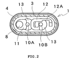
- Reference symbol 1 designates a thermally responsive switch, 2 a hermetic container, 3 a housing, 4 a header plate, 6 a thermally responsive plate, 7 a movable contact, 8 a fixed contact, 9 a filler, and 10A and 10B conductive terminal pins.
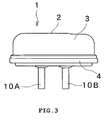
- FIGS. 3 and 4 are side and plan views of a thermally responsive switch respectively, FIG. 1 is a longitudinal section thereof, and FIG. 2 is a cross section taken along line II-II in FIG. 1 .
- the thermally responsive switch 1 comprises a hermetically sealed container 2 including a metal housing 3 and a header plate 4.
- the housing 3 is formed into an elongate dome shape by drawing an iron plate or the like by a press machine so as to have both lengthwise ends each formed into a substantially spherical shape and a middle portion connecting the ends.
- the header plate 4 is formed by shaping an iron plate thicker than the housing 3 into an oval and is hermetically sealed to an open end of the housing 3 by the ring projection welding or the like.
- a thermally responsive plate 6 has one end fixed via a support 5 made of a metal plate to an inside of the container 2.
- the thermally responsive plate 6 is formed by drawing a thermally responsive member such as a bimetal or trimetal into a shallow dish shape and is designed to reverse a direction of curvature with a snap action when the thermally responsive member reaches a predetermined temperature.
- a movable contact 7 is secured to the other end of the thermally responsive plate 6.
- a part of the container 2 to which the support 5 is fixed is externally collapsed thereby to be deformed, so that a contact pressure is adjustable between the fixed contact 7 and a movable contact 8 which will be described later, whereupon a temperature at which the thermally responsive plate 6 reverses the direction of curvature can be calibrated to a predetermined value.
- the header plate 4 has two through holes 4A and 4B through which electrically conductive terminal pins 10A and 10B are inserted and hermetically fixed in the through holes by an electrically insulating filler 9 such as glass or the like in view of a thermal expansion coefficient by a well-known hermetic compression sealing.
- a contact support 11 is secured to a part of the terminal pin 10A near to the distal end of the pin inside the hermetically sealed container 2.
- the fixed contact 8 is secured to a part of the contact support 11 opposed to the movable contact 7.
- Each of the movable and fixed contacts 7 and 8 comprises a silver-tin oxide-indium oxide (Ag-(Sn-In)Ox) contact containing 9.7 weight percentage metal oxide.
- Each of the contacts 7 and 8 is formed into a three layer structure including an intermediate layer of copper and a lower layer of iron.
- Each contact has the shape of a disc having a diameter ranging from 3 mm to 5 mm and a slightly convexly curved surface (a sphere having a radius of 8 mm in the embodiment, for example).
- a heater 12 serving as a heating element has one of two ends fixed to a portion of the terminal pin 10B located near the distal end of the terminal pin inside the hermetically sealed container 2. The other end of the heater 12 is fixed to the header plate 4. The heater 12 is disposed so as to be substantially parallel to the thermally responsive plate 6 along the terminal pin 10B, so that heat generated by the heater 12 is efficiently transmitted to the thermally responsive plate 6.
- the heater 12 is provided with a fusing portion 12A having a smaller sectional area than the other part thereof.
- the fusing portion 12A is prevented from being fused by an operating current of an electric motor during a normal operation of a compressor serving as an equipment to be controlled. Furthermore, the fusing portion 12A is further prevented from being fused upon occurrence of a locked rotor condition of the motor since the thermally responsive plate 6 reverses its direction of curvature thereby to open the contacts 7 and 8 in a short period of time.
- the thermally responsive switch 1 repeats the opening and closure of the contacts for a long period of time such that the number of times of switching exceeds a guaranteed number of switching operations, the movable and fixed contacts 7 and 8 are sometimes welded together thereby to be inseparable from each other.
- a temperature of the fusing portion 12A is increased by an excessively large current such that the fusing portion is fused, whereupon power supply to the motor can reliably be cut off.
- the container 2 is filled with a gas containing helium (He) ranging from 50% to 95% so that an internal pressure of the container 2 ranges from 0.25 atm. to 0.8 atm. at room temperature, as will be described later.
- the gas filling the container 2 contains nitrogen, dried air, carbon dioxide and the like other than helium.
- the container 2 is filled with helium as an inert gas for the following reason. That is, helium has such a good heat conductivity that upon occurrence of an excessively large current, a period of time (short time trip (S/T)) necessitated for the opening of the contacts 7 and 8 by heat generated by the heater 12 can be shortened as described in prior art document 2.
- S/T short time trip
- a minimum operating current value (an ultimate trip current (UTC)) can be increased as compared with the conventional thermal protectors.
- UTC ultimate trip current
- the thermally responsive plate 6 is configured so that its resistance value is increased for the purpose of increasing a heating value thereof, heat generated by the plate 6 as the result of the filling of the container 2 with helium can efficiently be allowed to escape. Consequently, the aforesaid short time trip (S/T) can be rendered longer.
- the breakdown voltage tends to be reduced when a helium charged rate is increased, the helium charged rate preferably ranges from 30% to 95% or particularly from 50% to 95% in the case of an ordinary commercial power supply ranging from AC 100 V to 260 V.
- a heat-resistant inorganic insulating member 13 comprising ceramics and zirconia (zirconium oxide).
- the heat-resistant inorganic insulating member 13 is configured in consideration of the physical strength such as resistance to a creeping discharge or resistance to heat due to sputter. Consequently, even when sputter occurring during meltdown by the heater 12 is adhered to the surface of the heat-resistant inorganic insulating member 13, a sufficient insulating performance can be maintained, whereupon arc generated between fusing portions can be prevented from transition to a space between the terminal pin 10B and the header plate 4 or a space between the terminal pins 10A and 10B.
- the thermally responsive switch 1 used as a thermal protector for the compressor motor necessitates the performance of cutting off an extremely large current such as constraint current flowing in the event of locked rotor condition or a short-circuit current flowing in the occurrence of a short circuit between the windings of the motor. Furthermore, the thermally responsive switch 1 necessitates a durability longer than a product's life of a refrigerating machine or an air conditioner in which the compressor to be protected is built. Additionally, the thermally responsive switch 1 needs to be small in size from the viewpoints of installation space and thermal responsiveness since the switch 1 is used in the hermetic housing of the enclosed electric compressor.
- Arc is generated between the contacts 7 and 8 when the contacts 7 and 8 are opened while an excessively large inductive current such as the aforesaid constraint current or short-circuit current is flowing.
- the durability (the guaranteed operation number) and current cutoff performance of the thermally responsive switch 1 may be improved, it is effective to shorten an arc-extinguishing time or to reduce damage due to arc. Damage due to arc sometimes spreads not only to the contacts 7 and 8 but also outside the contacts, for example, to the thermally responsive plate 6.
- the thermally responsive switch 1 of the embodiment is directed to protection of AC motors driven by a commercial power supply.
- Arc has a duration of ten and several ms (a half cycle) at the longest and of several ms on average. Then, the durability test was conducted so that high durability and high current cutoff performance can be achieved by reducing damage due to arc as much as possible but not by reducing the arc-extinguishing time. The structural optimization was carried out based on the results of the durability test.
- the motor was a single-phase induction motor having a rated voltage of 220 V (50 Hz), rated current of 10.8 A and rated power of 2320 W.
- a rotor of the motor was held so as to be prevented from rotation.
- a power supply under test was 240 V 50 Hz.
- the compressor was installed under the circumstance of room temperature (25°C).
- a constraint current at the start of the durability test (when the temperature of the motor was at room temperature) had the value of 60 A.
- the temperature of the motor rose as the result of repeated energization and de-energization, achieving equilibrium at the constraint current of 52 A.
- the thermally responsive switch 1 used in the durability test had the minimum operating current (UTC) ranging from 18.4 A to 25.4 A (120°C) and had a characteristic that the contacts 7 and 8 were opened in 3 to 10 seconds (S/T) upon flow of 54 A current.
- UTC minimum operating current
- S/T 3 to 10 seconds
- a constraint current of an electric motor is several times larger than a rated current, and a period of time (S/T) necessary for opening the contacts 7 and 8 is shortened to about several seconds by the heating of the motor, the heater 12 in the thermally responsive switch 1 and the thermally responsive plate 6 as described above.
- S/T period of time necessary for opening the contacts 7 and 8
- an interior temperature of the thermally responsive switch 1 gradually drops such that the contacts 7 and 8 are re-closed in about 2 minutes, whereby the motor is energized.
- the number of normally repeated switching operations was measured in the durability test. In each switching operation, energization by the constraint current (for several seconds) as the result of closing operation of the thermally responsive switch 1 and de-energization (about 2 minutes) as the result of an opening operation of the thermally responsive switch 1.
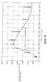
- FIG. 5 shows the results of the durability test in the case where a pressure of gas charged into the hermetic container 2 was varied.
- An axis of abscissas designates pressure (atmospheric pressure (atm.)), and an axis of ordinates designates the number of switching operations counted before reach of contact welding.
- FIG. 5 shows measured values and an interpolation curve of the minimum values in a plurality of samples.
- a charged gas comprised 90% helium and 10% dried air.
- Each of the movable and fixed contacts 7 and 8 comprised a silver-tin oxide-indium oxide system contact containing 9.7 weight percentage of metal oxide and had a three layer structure including an intermediate layer comprising copper and a lower layer comprising iron, the layers being deposited and pressed into a three layer structure together with the silver-tin oxide-indium oxide.
- Each contact was formed into the shape of a disc having a diameter of 4 mm and a thickness of 0.9 mm and had a contact surface formed into a spherical shape with a radius of 8 mm.
- An intercontact distance was 1.0 mm.
- the thermally responsive plate 6 was set to reverse its direction of curvature in the contact opening direction at the temperature of 160°C and in the contact closing direction at the temperature of 90°C.
- the number of switching operations was maximum (at or above 23000 times) at the pressure of about 0.4 atm. and was gradually reduced subsequently as the pressure was increased.
- the number of switching operations was about 20000 times (sampled minimum value) at 0.6 atm. and about 15000 times (sampled minimum value) at 0.8 atm.
- the number of switching operations was substantially constant at 7000 times (sampled minimum value) when the pressure exceeded 1.3 atm.
- the number of switching operations was gradually reduced when the pressure was reduced from about 0.4 atm. to about 0.3 atm.
- the number of switching operations was rapidly reduced to about 15000 times (sampled minimum value) at the pressure of 0.25 atm., about 8000 times (sampled minimum value) at 0.2 atm., and about 2000 times (sampled minimum value) at 0.1 atm.
- the thermally responsive switch 1 with the above-described structure, at least 15000 times or above can be guaranteed as the number of switching operations when the charged pressure ranges from 0.25 atm. to 0.8 atm. as shown by alternate long and short dash line and arrow in FIG. 5 . Furthermore, when the charged pressure ranges from 0.3 atm. to 0.6 atm., at least 20000 times or above can be guaranteed as the number of switching operations.
- FIGS. 6, 7 and 8 show the photographs of surfaces of the movable contact 7 (A-1 to A-3) and the fixed contact 8 (B-1 to B-3) after completion of the durability test when the charged pressure is at 0.5, 0.7 and 1.3 atm. respectively.
- the charged pressure is relatively higher as 1.3 atm. ( FIG. 8 )
- the charged pressure is relatively lower as 0.5 atm. ( FIG. 6 ) or 0.7 atm. ( FIG. 7 )
- arc moves on each contact surface without stopping at one portion.
- the durability is improved since the contact surface is uniformly worn, the forming of the protrusion is suppressed and the contact welding is suppressed.
- an upper limit of the intercontact distance is set as a value that can prevent the transition of arc out of the contacts according to the reduction in the charged pressure.
- the thermally responsive switch 1 of the embodiment has an intercontact distance ranging from 0.7 mm to 1.5 mm.
- the thermally responsive switch 1 may be constructed so as to have an increased space between the inner surface of the housing 3 and an upper surface of the thermally responsive plate 6, whereupon the curvature direction reversing operation is prevented from being limited in the middle thereof.
- the contacts 7 and 8 can be separated from each other with a longer distance therebetween by making use of a snap reversing force of the thermally responsive plate 6.
- the thermally responsive plate 6 is easy to break unless the reversing operation thereof is limited, whereupon the durability thereof is extremely reduced. Accordingly, the aforesaid upper limit of the intercontact distance, 1.5 mm, is a value structurally set as a distance necessary for the movable contact side end of the thermally responsive plate 6 to abut against the inner surface of the housing 3 in the middle of the curvature direction reversing operation.
- the thermally responsive switch 1 of the embodiment comprises the fixed contact 8 fixed to the conductive terminal pin 10A, the thermally responsive plate 6 reversing the direction of curvature according to the temperature, and the movable contact 7 secured to the free end of the thermally responsive plate 6, these components being enclosed in the hermetic container 2.
- Each of the movable and fixed contacts 7 and 8 comprises a silver-tin oxide-indium oxide system contact.
- the container 2 is filled with the gas containing helium (He) ranging from 50% to 95% so that the internal pressure of the container 2 ranges from 0.25 atm. to 0.8 atm. at room temperature or more preferably, from 0.3 atm. to 0.6 atm.
- He helium
- each of the contacts 7 and 8 has a durability performance equivalent to that of the conventional cadmium contact (a silver-cadmium oxide system contact, for example). Furthermore, since the container 2 is filled with helium that has a good heat conductivity, the time period necessitated for the opening of the contacts 7 and 8 upon the flow of an excessively large current such as the constraint current can be shortened (or increased depending upon the construction) and a rated working current value can be increased. An influence of the helium charged rate upon the durability of the switch is relatively smaller.
- a breakdown voltage can be ensured in the use of a commercial power supply since the intercontact distance is set at or above 0.7 mm. Furthermore, since the intercontact distance is set at a value equal to or smaller than 1.5 mm, arc can be prevented from spreading out of the gap between the contacts 7 and 8 as much as possible, and the reduction in the durability can be prevented by suppressing damage due to arc to peripheral components such as the thermally responsive plate 6. Furthermore, when the intercontact distance is set a value equal to or smaller than 1.5 mm, the movable-contact side end of the thermally responsive plate 6 abuts against the inner surface of the housing 3 in the middle of the contact opening operation. This can prevent an excessive displacement of the thermally responsive plate 6 by the snap curvature direction reversing operation and subsequent occurrence of vibration, whereupon reduction in the durability can be prevented.
- the disc having the diameter ranging from 3 mm to 5 mm is used as each of the movable and fixed contacts 7 and 8.
- the durability of each contact against the heat due to arc is improved when the size of each contact is increased.
- a main material of each contact is silver, costs are increased considerably.
- each contact with a reduced size is advantageous in cost reduction.
- it is experimentally confirmed that each contact with the diameter of 3 mm at the smallest is necessitated in order that the durability performance against current of 60 A may be ensured.
- using each contact with the diameter equal to or larger than 5 mm, for example, with the diameter of 6 mm is possible and improves the durability.
- such contact is impractical from the viewpoints of costs and the size of the thermally responsive switch.
- the durability and current cutoff performance of the thermally responsive switch 1 are improved without rendering the contacts 7 and 8 and the thermally responsive plate 6 larger in size. Consequently, the thermally responsive switch 1 can easily be housed in the hermetic housing of the compressor motor and is accordingly suitable for a thermal protector for the compressor motor.
- the invention should not be limited by the above-described embodiment.
- the embodiment may be modified as follows, for example.
- the hermetic container 2 is filled with the gas containing helium ranging from 50% to 95% so that an internal pressure of the container 2 ranges from 0.25 atm. to 0.8 atm. at room temperature.
- this is an indispensable feature, the intercontact distance, the shape and size of the contacts 7 and 8 should not be limited by the above-described numerical ranges.
- the shape of the hermetic container 2 should not be limited to the elongate dome shape.
- the shape of the hermetic container 2 may or may not be the elongate dome shape.
- the support 5 is fixed to one end of the hermetic container 2, the thermally responsive plate 6 may be fixed in the vicinity of the center of the hermetic container 2 when the thermally responsive switch is rendered further smaller.
- the support 5 may have a button shape and may be eliminated.
- the heater 12 and the heat-resistant inorganic insulating member 13 may be provided as occasion demands.
- the header plate 4 is provided with two terminal pins 10A and 10B, only one terminal pin may be provided and the metal header plate 4 may serve as the other terminal.
- Two or more pairs of switching contacts 7 and 8 may be provided. At least one of the movable and fixed contacts 7 and 8 may have a convexly curved surface. Furthermore, a flat portion may be provided on a top of the convexly curved surface.
- the motor for which the thermally responsive switch is used as the thermal protector should not be limited to the single-phase induction motor but may include three-phase induction motors. Furthermore, the thermally responsive switch may be applied to other types of electric motors, for example, motors to which AC voltage is applied, such as synchronous motors.
- the thermally responsive switch of the invention is useful as a thermal protector for a compressor motor.
Description
- The present invention relates to a thermally responsive switch having a contact switching mechanism using a thermally responsive plate such as a bimetal in a hermetic container.
- Thermally responsive switches of this type are disclosed in Japanese patent No.
2519530 JP-A-H10-144189 JP-A-2002-352685 JP-A-2003-59379 - The thermally responsive switch is mounted in a closed housing of a hermetic electric compressor thereby to be used as a thermal protector for an electric motor of the compressor. In this case, windings of the motor are connected to the terminal pin or the header plate. The thermally responsive plate reverses the direction of curvature when a temperature around the thermally responsive switch becomes unusually high or when an abnormal current flows in the motor. When the temperature drops to or below a predetermined value, the contacts are re-closed such that the compressor motor is energized.
- The document
US 5 015 985 A "discloses a thermally responsive swith according to the preamble ofclaim 1. - The thermally responsive switch is required to open the contacts upon every occurrence of the aforesaid abnormal condition until a refrigerating machine or air conditioner in which the compressor is built reaches an end of product's life. The thermally responsive switch needs to cut off current extremely larger than a rated current of the motor particularly when a motor is driven in a locked rotor condition or when a short occurs between motor windings. When current having such a large inductivity is cut off by the opening of contacts, arc is generated between the contacts, whereupon contact surfaces are damaged by heat due to arc. The welding of contacts occurs when the switching of contacts exceeds a guaranteed operation number. In this regard, in order that an electric path may be cut off even upon occurrence of contact welding for the purpose of preventing secondary abnormality, double safety and protective measures are taken when needed (a fusing portion of a heater described in
prior art documents - The use of a contact containing cadmium has recently been limited for environmental reasons. For example, a silver-cadmium oxide (Ag-CdO) system contact has a small contact welding force such that the silver-cadmium oxide system contact has less wear due to arc. Accordingly, the silver-cadmium oxide system contact has been used in a large number of thermally responsive switches. Equivalent durability and current cutoff performance to those of the conventional thermally responsive switches need to be ensured by the use of an alternative contact material in the future. The current cutoff performance would be reduced by half when the silver-cadmium oxide system contact is merely replaced by a cadmiumless contact.
- In order that the current cutoff performance may be improved, a structure is considered in which the size of the contacts is increased for the purpose of increasing the heat capacity, whereby occurrence of contact welding is reduced even upon occurrence of arc. Furthermore, another structure is considered in which the size of the thermal responsive plate is increased so that a force separating the contacts from each other is increased. However, when either construction is employed, the thermally responsive switch would be rendered larger in size, whereupon it would become difficult to mount the thermally responsive switch in the hermetic housing of the compressor.
- An object of the present invention is to provide a thermally responsive switch which uses cadmiumless contacts and is small in size and has a high durability and current cutoff performance.
- The present invention provides a thermally responsive switch which is used to cut off AC current flowing through a compressor motor, the thermally responsive switch comprising a hermetically sealed container including a metal housing and a header plate hermetically secured to an open end of the housing, at least one conductive terminal pin inserted through a through hole formed through the header plate and hermetically fixed in the through hole by an electrically insulating filler, a fixed contact fixed to the terminal pin in the container, a thermally responsive plate having one of two ends conductively connected and fixed to an inner surface of the container and formed into a dish shape by drawing so as to reverse a direction of curvature at a predetermined temperature, at least one movable contact secured to the other end of the thermally responsive plate and constituting at least one pair of switching contacts together with the fixed contact, wherein each of the fixed contact and the movable contact comprises a silver-tin oxide-indium oxide system contact, and the container is filled with a gas containing helium ranging from 50% to 95% so that an internal pressure of the container ranges from 0.25 atmosphere to 0.8 atmosphere at room temperature or more preferably from 0.3 atmosphere to 0.6 atmosphere.
- According to the invention, the thermally responsive switch is resistant to local damage due to arc since the arc generated by the opening of the contacts moves on each contact. Consequently, the thermally responsive switch has a small size and an improved durability and can achieve a high current cutoff performance even though cadmiumless contacts are used.
-
- [
FIG. 1] FIG. 1 is a longitudinal section of a thermally responsive switch of one embodiment in accordance with the present invention; - [
FIG. 2] FIG. 2 is a cross section taken along line II-II inFIG. 1 ; - [
FIG. 3] FIG. 3 is a side view of the thermally responsive switch; - [
FIG. 4] FIG. 4 is a plan view of the thermally responsive switch; - [
FIG. 5] FIG. 5 is a graph showing results of a durability test in the case where a gas charged pressure is varied; - [
FIG. 6] FIG. 6 shows surface conditions of a movable contact (A) and a fixed contact (B) after end of the durability test in the case where the gas charged pressure is at 0.5 atmosphere respectively; - [
FIG. 7] FIG. 7 is a view similar toFIG. 6 in the case where the gas charged pressure is at 0.7 atmosphere respectively; and - [
FIG. 8] FIG. 8 is a view similar toFIG. 6 in the case where the gas charged pressure is at 1. 3 atmosphere respectively. -
Reference symbol 1 designates a thermally responsive switch, 2 a hermetic container, 3 a housing, 4 a header plate, 6 a thermally responsive plate, 7 a movable contact, 8 a fixed contact, 9 a filler, and 10A and 10B conductive terminal pins. - One embodiment will be described with reference to the drawings. The present invention is applied to a thermal protector for an electric motor of a compressor in the embodiment.
FIGS. 3 and4 are side and plan views of a thermally responsive switch respectively,FIG. 1 is a longitudinal section thereof, andFIG. 2 is a cross section taken along line II-II inFIG. 1 . The thermallyresponsive switch 1 comprises a hermetically sealedcontainer 2 including ametal housing 3 and aheader plate 4. Thehousing 3 is formed into an elongate dome shape by drawing an iron plate or the like by a press machine so as to have both lengthwise ends each formed into a substantially spherical shape and a middle portion connecting the ends. Theheader plate 4 is formed by shaping an iron plate thicker than thehousing 3 into an oval and is hermetically sealed to an open end of thehousing 3 by the ring projection welding or the like. - A thermally
responsive plate 6 has one end fixed via asupport 5 made of a metal plate to an inside of thecontainer 2. The thermallyresponsive plate 6 is formed by drawing a thermally responsive member such as a bimetal or trimetal into a shallow dish shape and is designed to reverse a direction of curvature with a snap action when the thermally responsive member reaches a predetermined temperature. Amovable contact 7 is secured to the other end of the thermallyresponsive plate 6. A part of thecontainer 2 to which thesupport 5 is fixed is externally collapsed thereby to be deformed, so that a contact pressure is adjustable between the fixedcontact 7 and amovable contact 8 which will be described later, whereupon a temperature at which the thermallyresponsive plate 6 reverses the direction of curvature can be calibrated to a predetermined value. - The
header plate 4 has two throughholes conductive terminal pins 10A and 10B are inserted and hermetically fixed in the through holes by an electrically insulatingfiller 9 such as glass or the like in view of a thermal expansion coefficient by a well-known hermetic compression sealing. Acontact support 11 is secured to a part of theterminal pin 10A near to the distal end of the pin inside the hermetically sealedcontainer 2. The fixedcontact 8 is secured to a part of thecontact support 11 opposed to themovable contact 7. - Each of the movable and
fixed contacts contacts - A
heater 12 serving as a heating element has one of two ends fixed to a portion of the terminal pin 10B located near the distal end of the terminal pin inside the hermetically sealedcontainer 2. The other end of theheater 12 is fixed to theheader plate 4. Theheater 12 is disposed so as to be substantially parallel to the thermallyresponsive plate 6 along the terminal pin 10B, so that heat generated by theheater 12 is efficiently transmitted to the thermallyresponsive plate 6. - The
heater 12 is provided with a fusingportion 12A having a smaller sectional area than the other part thereof. The fusingportion 12A is prevented from being fused by an operating current of an electric motor during a normal operation of a compressor serving as an equipment to be controlled. Furthermore, the fusingportion 12A is further prevented from being fused upon occurrence of a locked rotor condition of the motor since the thermallyresponsive plate 6 reverses its direction of curvature thereby to open thecontacts responsive switch 1 repeats the opening and closure of the contacts for a long period of time such that the number of times of switching exceeds a guaranteed number of switching operations, the movable and fixedcontacts portion 12A is increased by an excessively large current such that the fusing portion is fused, whereupon power supply to the motor can reliably be cut off. - The
container 2 is filled with a gas containing helium (He) ranging from 50% to 95% so that an internal pressure of thecontainer 2 ranges from 0.25 atm. to 0.8 atm. at room temperature, as will be described later. The gas filling thecontainer 2 contains nitrogen, dried air, carbon dioxide and the like other than helium. Thecontainer 2 is filled with helium as an inert gas for the following reason. That is, helium has such a good heat conductivity that upon occurrence of an excessively large current, a period of time (short time trip (S/T)) necessitated for the opening of thecontacts heater 12 can be shortened as described inprior art document 2. Furthermore, a minimum operating current value (an ultimate trip current (UTC)) can be increased as compared with the conventional thermal protectors. Additionally, when the thermallyresponsive plate 6 is configured so that its resistance value is increased for the purpose of increasing a heating value thereof, heat generated by theplate 6 as the result of the filling of thecontainer 2 with helium can efficiently be allowed to escape. Consequently, the aforesaid short time trip (S/T) can be rendered longer. However, since the breakdown voltage tends to be reduced when a helium charged rate is increased, the helium charged rate preferably ranges from 30% to 95% or particularly from 50% to 95% in the case of an ordinary commercial power supply ranging from AC 100 V to 260 V. - On the
filler 9 fixing theterminal pins 10A and 10B is closely fixed a heat-resistant inorganic insulatingmember 13 comprising ceramics and zirconia (zirconium oxide). The heat-resistant inorganic insulatingmember 13 is configured in consideration of the physical strength such as resistance to a creeping discharge or resistance to heat due to sputter. Consequently, even when sputter occurring during meltdown by theheater 12 is adhered to the surface of the heat-resistant inorganic insulatingmember 13, a sufficient insulating performance can be maintained, whereupon arc generated between fusing portions can be prevented from transition to a space between the terminal pin 10B and theheader plate 4 or a space between theterminal pins 10A and 10B. - When current flowing into the motor is a normal operation current including a short-duration starting current, the
contacts responsive switch 1 remain closed, so that the motor continues running. On the other hand, the thermallyresponsive plate 6 reverses the direction of curvature thereof to open thecontacts responsive switch 1 drops, the thermallyresponsive plate 6 again reverses the direction of curvature thereof such that thecontacts - Next, the following describes optimization of the structure of the thermally
responsive switch 1 based on the durability test. The thermallyresponsive switch 1 used as a thermal protector for the compressor motor necessitates the performance of cutting off an extremely large current such as constraint current flowing in the event of locked rotor condition or a short-circuit current flowing in the occurrence of a short circuit between the windings of the motor. Furthermore, the thermallyresponsive switch 1 necessitates a durability longer than a product's life of a refrigerating machine or an air conditioner in which the compressor to be protected is built. Additionally, the thermallyresponsive switch 1 needs to be small in size from the viewpoints of installation space and thermal responsiveness since theswitch 1 is used in the hermetic housing of the enclosed electric compressor. - Arc is generated between the
contacts contacts responsive switch 1 may be improved, it is effective to shorten an arc-extinguishing time or to reduce damage due to arc. Damage due to arc sometimes spreads not only to thecontacts responsive plate 6. - Known means for reducing the arc-extinguishing time include high pressurization or extremely low pressurization of filling gas (vacuuming), an increase in the intercontact gap, the mounting of an arcing horn, magnetic induction of arc and arc blowout. However, these means result in significant reduction in the production efficiency, complicated structure and an increase in the size of the thermally
responsive switch 1. Accordingly, the means are unsuitable for the thermally responsive switches protecting relatively smaller motors used in compressors. - The thermally
responsive switch 1 of the embodiment is directed to protection of AC motors driven by a commercial power supply. Arc has a duration of ten and several ms (a half cycle) at the longest and of several ms on average. Then, the durability test was conducted so that high durability and high current cutoff performance can be achieved by reducing damage due to arc as much as possible but not by reducing the arc-extinguishing time. The structural optimization was carried out based on the results of the durability test. - In the durability test, an upper part of the hermetic housing of the compressor in which the motor is built is cut, and the thermally
responsive switch 1 was mounted in the compressor. Subsequently, the compressor was installed on a test bench, and the thermallyresponsive switch 1 repeated a switching operation under the condition that an excessively large current flowed into the motor. - The motor was a single-phase induction motor having a rated voltage of 220 V (50 Hz), rated current of 10.8 A and rated power of 2320 W. A rotor of the motor was held so as to be prevented from rotation. A power supply under test was 240 V 50 Hz. The compressor was installed under the circumstance of room temperature (25°C). A constraint current at the start of the durability test (when the temperature of the motor was at room temperature) had the value of 60 A. The temperature of the motor rose as the result of repeated energization and de-energization, achieving equilibrium at the constraint current of 52 A. The thermally
responsive switch 1 used in the durability test had the minimum operating current (UTC) ranging from 18.4 A to 25.4 A (120°C) and had a characteristic that thecontacts - A constraint current of an electric motor is several times larger than a rated current, and a period of time (S/T) necessary for opening the
contacts heater 12 in the thermallyresponsive switch 1 and the thermallyresponsive plate 6 as described above. Upon opening of thecontacts responsive switch 1 gradually drops such that thecontacts responsive switch 1 and de-energization (about 2 minutes) as the result of an opening operation of the thermallyresponsive switch 1. - When the
contacts contacts responsive plate 6 was damaged by the arc depending upon the intercontact distance. Furthermore, since the thermallyresponsive plate 6 repeated reversing the direction of curvature with snap action every time of switching, the thermallyresponsive plate 6 was sometimes broken by fatigue before occurrence of contact welding when the switching number became excessively large. -
FIG. 5 shows the results of the durability test in the case where a pressure of gas charged into thehermetic container 2 was varied. An axis of abscissas designates pressure (atmospheric pressure (atm.)), and an axis of ordinates designates the number of switching operations counted before reach of contact welding.FIG. 5 shows measured values and an interpolation curve of the minimum values in a plurality of samples. A charged gas comprised 90% helium and 10% dried air. Each of the movable and fixedcontacts responsive plate 6 was set to reverse its direction of curvature in the contact opening direction at the temperature of 160°C and in the contact closing direction at the temperature of 90°C. - According to the test results as shown in
FIG. 5 , the number of switching operations was maximum (at or above 23000 times) at the pressure of about 0.4 atm. and was gradually reduced subsequently as the pressure was increased. The number of switching operations was about 20000 times (sampled minimum value) at 0.6 atm. and about 15000 times (sampled minimum value) at 0.8 atm. The number of switching operations was substantially constant at 7000 times (sampled minimum value) when the pressure exceeded 1.3 atm. On the other hand, the number of switching operations was gradually reduced when the pressure was reduced from about 0.4 atm. to about 0.3 atm. When the pressure was reduced to or below 0.3 atm., the number of switching operations was rapidly reduced to about 15000 times (sampled minimum value) at the pressure of 0.25 atm., about 8000 times (sampled minimum value) at 0.2 atm., and about 2000 times (sampled minimum value) at 0.1 atm. - More specifically, in the thermally
responsive switch 1 with the above-described structure, at least 15000 times or above can be guaranteed as the number of switching operations when the charged pressure ranges from 0.25 atm. to 0.8 atm. as shown by alternate long and short dash line and arrow inFIG. 5 . Furthermore, when the charged pressure ranges from 0.3 atm. to 0.6 atm., at least 20000 times or above can be guaranteed as the number of switching operations. -
FIGS. 6, 7 and8 show the photographs of surfaces of the movable contact 7 (A-1 to A-3) and the fixed contact 8 (B-1 to B-3) after completion of the durability test when the charged pressure is at 0.5, 0.7 and 1.3 atm. respectively. When the charged pressure is relatively higher as 1.3 atm. (FIG. 8 ), arc stops at one portion of each contact. Accordingly, the surface of each contact is locally melted such that a protrusion is formed. It can be considered that the portion of the protrusion tends to be easily deposited such that the durability is reduced. On the other hand, when the charged pressure is relatively lower as 0.5 atm. (FIG. 6 ) or 0.7 atm. (FIG. 7 ), arc moves on each contact surface without stopping at one portion. As a result, it can be considered that the durability is improved since the contact surface is uniformly worn, the forming of the protrusion is suppressed and the contact welding is suppressed. - However, when the charged pressure is reduced such that arc is easier to move, there is a possibility that arc may move out of the gap between the
contacts contacts responsive plate 6, the thermallyresponsive plate 6 is damaged such that the durability is rather reduced. Furthermore, insufficient breakdown voltage results in continuance of arc even at zero crossing of current. In this case, the durability is extremely lowered. An extreme reduction in the number of switching operations at the pressure of 0.1 atm. inFIG. 5 mainly arises from the above-described two reasons. Accordingly, an upper limit of the intercontact distance is set as a value that can prevent the transition of arc out of the contacts according to the reduction in the charged pressure. On the other hand, a lower limit of the intercontact distance is determined from the necessity to ensure the breakdown voltage. As the result of inspection of experimental results, it is preferable that the thermallyresponsive switch 1 of the embodiment has an intercontact distance ranging from 0.7 mm to 1.5 mm. - When the
contacts responsive plate 6 abuts against the inner surface of thehousing 3 during the curvature direction reversing operation, so that further curvature direction reversing operation is limited. On the other hand, the thermallyresponsive switch 1 may be constructed so as to have an increased space between the inner surface of thehousing 3 and an upper surface of the thermallyresponsive plate 6, whereupon the curvature direction reversing operation is prevented from being limited in the middle thereof. When the thermallyresponsive switch 1 is constructed as described above, thecontacts responsive plate 6. Although this construction is regarded as effective for arc extinction, the thermallyresponsive plate 6 is easy to break unless the reversing operation thereof is limited, whereupon the durability thereof is extremely reduced. Accordingly, the aforesaid upper limit of the intercontact distance, 1.5 mm, is a value structurally set as a distance necessary for the movable contact side end of the thermallyresponsive plate 6 to abut against the inner surface of thehousing 3 in the middle of the curvature direction reversing operation. - As described above, the thermally
responsive switch 1 of the embodiment comprises the fixedcontact 8 fixed to the conductiveterminal pin 10A, the thermallyresponsive plate 6 reversing the direction of curvature according to the temperature, and themovable contact 7 secured to the free end of the thermallyresponsive plate 6, these components being enclosed in thehermetic container 2. Each of the movable and fixedcontacts container 2 is filled with the gas containing helium (He) ranging from 50% to 95% so that the internal pressure of thecontainer 2 ranges from 0.25 atm. to 0.8 atm. at room temperature or more preferably, from 0.3 atm. to 0.6 atm. - According to this construction, the arc generated during the opening of the
contacts contacts container 2 is filled with helium that has a good heat conductivity, the time period necessitated for the opening of thecontacts - In this case, a breakdown voltage can be ensured in the use of a commercial power supply since the intercontact distance is set at or above 0.7 mm. Furthermore, since the intercontact distance is set at a value equal to or smaller than 1.5 mm, arc can be prevented from spreading out of the gap between the
contacts responsive plate 6. Furthermore, when the intercontact distance is set a value equal to or smaller than 1.5 mm, the movable-contact side end of the thermallyresponsive plate 6 abuts against the inner surface of thehousing 3 in the middle of the contact opening operation. This can prevent an excessive displacement of the thermallyresponsive plate 6 by the snap curvature direction reversing operation and subsequent occurrence of vibration, whereupon reduction in the durability can be prevented. - The disc having the diameter ranging from 3 mm to 5 mm is used as each of the movable and fixed
contacts - Thus, the durability and current cutoff performance of the thermally
responsive switch 1 are improved without rendering thecontacts responsive plate 6 larger in size. Consequently, the thermallyresponsive switch 1 can easily be housed in the hermetic housing of the compressor motor and is accordingly suitable for a thermal protector for the compressor motor. - The invention should not be limited by the above-described embodiment. The embodiment may be modified as follows, for example. The
hermetic container 2 is filled with the gas containing helium ranging from 50% to 95% so that an internal pressure of thecontainer 2 ranges from 0.25 atm. to 0.8 atm. at room temperature. Although this is an indispensable feature, the intercontact distance, the shape and size of thecontacts - The shape of the
hermetic container 2 should not be limited to the elongate dome shape. For example, when a certain strength can be achieved by providing ribs along the lengthwise direction of thehermetic container 2, the shape of thehermetic container 2 may or may not be the elongate dome shape. Although thesupport 5 is fixed to one end of thehermetic container 2, the thermallyresponsive plate 6 may be fixed in the vicinity of the center of thehermetic container 2 when the thermally responsive switch is rendered further smaller. Thesupport 5 may have a button shape and may be eliminated. - The
heater 12 and the heat-resistant inorganic insulatingmember 13 may be provided as occasion demands. Although theheader plate 4 is provided with twoterminal pins 10A and 10B, only one terminal pin may be provided and themetal header plate 4 may serve as the other terminal. - Two or more pairs of switching
contacts contacts - The motor for which the thermally responsive switch is used as the thermal protector should not be limited to the single-phase induction motor but may include three-phase induction motors. Furthermore, the thermally responsive switch may be applied to other types of electric motors, for example, motors to which AC voltage is applied, such as synchronous motors.
- As described above, the thermally responsive switch of the invention is useful as a thermal protector for a compressor motor.
Claims (12)
- A thermally responsive switch which is used to cut off AC current flowing through a compressor motor, the thermally responsive switch comprising:a hermetically sealed container (2) including a metal housing (3) and a header plate (4) hermetically secured to an open end of the housing (3);at least one conductive terminal pin (10A, 10B) inserted through a through hole (4A, 4B) formed through the header plate (4) and hermetically fixed in the through hole (4A, 4B) by an electrically insulating filler (9);a fixed contact (8) fixed to the terminal pin (10A, 10B) in the container (2);a thermally responsive plate (6) having one of two ends conductively connected and fixed to an inner surface of the container (2) and formed into a dish shape by drawing so as to reverse a direction of curvature at a predetermined temperature;at least one movable contact (7) secured to the other end of the thermally responsive plate (6) and constituting at least one pair of switching contacts together with the fixed contact (8),characterised in that each of the fixed contact (8) and the movable contact (7) comprises a silver-tin oxide-indium oxide system contact, and the container (2) is filled with a gas containing helium ranging from 50% to 95% so that an internal pressure of the container (2) ranges from 0.25 atmosphere to 0.8 atmosphere at room temperature.
- The thermally responsive switch according to claim 1, wherein the container (2) is filled with the gas so that the internal pressure of the container (2) ranges from 0.3 atmosphere to 0.6 atmosphere at room temperature.
- The thermally responsive switch according to claim 1, wherein the movable contact (7) and the fixed contact (8) have an intercontact distance therebetween in an open state, the intercontact distance being set at or above 0.7 mm so that the thermally responsive plate (6) abuts against the inner surface of the container (2) during a contact opening operation and so that a subsequent operation of the thermally responsive plate (6) is limited during a curvature direction reversing operation.
- The thermally responsive switch according to claim 2, wherein the movable contact (7) and the fixed contact (8) have an intercontact distance therebetween in an open state, the intercontact distance being set at or above 0.7 mm so that the thermally responsive plate (6) abuts against the inner surface of the container (2) during a contact opening operation and so that a subsequent operation of the thermally responsive plate (6) is limited during a curvature direction reversing operation.
- The thermally responsive switch according to claim 1, wherein each of the fixed contact (8) and the movable contact (7) is formed into a disc shape having a diameter ranging from 3 mm to 5 mm.
- The thermally responsive switch according to claim 2, wherein each of the fixed contact (8) and the movable contact (7) is formed into a disc shape having a diameter ranging from 3 mm to 5 mm.
- The thermally responsive switch according to claim 3, wherein each of the fixed contact (8) and the movable contact (7) is formed into a disc shape having a diameter ranging from 3 mm to 5 mm.
- The thermally responsive switch according to claim 4, wherein each of the fixed contact (8) and the movable contact (7) is formed into a disc shape having a diameter ranging from 3 mm to 5 mm.
- The thermally responsive switch according to claim 5, wherein at least one of the fixed contact (8) and the movable contact (7) has a convexly curved surface.
- The thermally responsive switch according to claim 6, wherein at least one of the fixed contact (8) and the movable contact (7) has a convexly curved surface.
- The thermally responsive switch according to claim 7, wherein at least one of the fixed contact (8) and the movable contact (7) has a convexly curved surface.
- The thermally responsive switch according to claim 8, wherein at least one of the fixed contact (8) and the movable contact (7) has a convexly curved surface.
Applications Claiming Priority (2)
| Application Number | Priority Date | Filing Date | Title |
|---|---|---|---|
| JP2006315853 | 2006-08-10 | ||
| PCT/JP2007/065551 WO2008018515A1 (en) | 2006-08-10 | 2007-08-08 | Thermally reactive switch |
Publications (3)
| Publication Number | Publication Date |
|---|---|
| EP2051273A1 EP2051273A1 (en) | 2009-04-22 |
| EP2051273A4 EP2051273A4 (en) | 2011-10-12 |
| EP2051273B1 true EP2051273B1 (en) | 2013-08-07 |
Family
ID=39033045
Family Applications (1)
| Application Number | Title | Priority Date | Filing Date |
|---|---|---|---|
| EP07792218.5A Active EP2051273B1 (en) | 2006-08-10 | 2007-08-08 | Thermally reactive switch |
Country Status (10)
| Country | Link |
|---|---|
| US (1) | US8902037B2 (en) |
| EP (1) | EP2051273B1 (en) |
| KR (1) | KR101053738B1 (en) |
| CN (1) | CN101501803B (en) |
| BR (1) | BRPI0716646B1 (en) |
| CA (1) | CA2659856C (en) |
| MX (1) | MX2009001486A (en) |
| MY (1) | MY158649A (en) |
| RU (1) | RU2388098C1 (en) |
| WO (1) | WO2008018515A1 (en) |
Families Citing this family (8)
| Publication number | Priority date | Publication date | Assignee | Title |
|---|---|---|---|---|
| BRPI0716646B1 (en) | 2006-08-10 | 2018-07-31 | Ubukata Industries Co., Ltd. | THERMAL RESPONSE SWITCH |
| JP5001279B2 (en) * | 2006-08-10 | 2012-08-15 | 株式会社生方製作所 | Thermally sensitive switch |
| EP2412828B1 (en) * | 2007-03-13 | 2013-06-05 | Amgen Inc. | K-ras and B-raf mutations and anti-EGFr antibody therapy |
| BRPI0822256B1 (en) * | 2008-02-08 | 2018-10-09 | Ubukata Ind Co Ltd | thermal response switch |
| CN104919559B (en) * | 2013-01-21 | 2017-03-08 | 株式会社生方制作所 | Thermal switch and its height adjuster of manufacture method and moving contact |
| CN104217896B (en) * | 2014-09-15 | 2016-06-08 | 匡成效 | A kind of built-in overcurrent overheat protector |
| MX2017008214A (en) * | 2014-12-24 | 2017-10-06 | Ubukata Ind Co Ltd | Thermal response switch. |
| US11509159B2 (en) * | 2019-08-28 | 2022-11-22 | Microsoft Technology Licensing, Llc | System and method for thermal cutoff protection device control from an external component |
Family Cites Families (55)
| Publication number | Priority date | Publication date | Assignee | Title |
|---|---|---|---|---|
| US2239540A (en) | 1936-01-27 | 1941-04-22 | Metals & Controis Corp | Thermostatic control |
| US2280550A (en) * | 1939-08-12 | 1942-04-21 | Gen Electric | Thermal switch |
| US2284103A (en) * | 1939-09-20 | 1942-05-26 | Gen Electric | Thermal switch |
| US2667553A (en) * | 1951-09-25 | 1954-01-26 | Metals & Controls Corp | Hermetically sealed thermostat |
| US3140370A (en) * | 1960-03-17 | 1964-07-07 | Texas Instruments Inc | Sealed thermally responsive switching device |
| US3278706A (en) | 1964-11-23 | 1966-10-11 | Sylvania Electric Prod | Encapsulated thermostatic switch with shunt |
| JPS5526697B2 (en) * | 1973-07-05 | 1980-07-15 | ||
| JPS523193A (en) * | 1975-06-24 | 1977-01-11 | Sumitomo Electric Ind Ltd | Electric contact material |
| US4114127A (en) * | 1976-09-30 | 1978-09-12 | Texas Instruments Incorporated | Current interrupting apparatus |
| US4167721A (en) * | 1977-09-15 | 1979-09-11 | Texas Instruments Incorporated | Hermetic motor protector |
| JPS54103570A (en) | 1978-02-02 | 1979-08-15 | Susumu Ubukata | Closed thermoswitch |
| US4287499A (en) * | 1978-12-29 | 1981-09-01 | Texas Instruments Incorporated | Current interrupting apparatus having improved contact life |
| US4376926A (en) * | 1979-06-27 | 1983-03-15 | Texas Instruments Incorporated | Motor protector calibratable by housing deformation having improved sealing and compactness |
| DE3027304C2 (en) | 1980-07-18 | 1982-09-30 | Sds-Elektro Gmbh, 8024 Deisenhofen | Electrical multilayer contact |
| US4426560A (en) | 1980-11-13 | 1984-01-17 | Westinghouse Electric Corp. | Reduced pressure electrical switch |
| US4476452A (en) * | 1982-09-27 | 1984-10-09 | Texas Instruments Incorporated | Motor protector |
| DE3402372A1 (en) * | 1984-01-25 | 1985-08-01 | Doduco KG Dr. Eugen Dürrwächter, 7530 Pforzheim | ELECTRICAL SWITCHING ELEMENT |
| US4555686A (en) * | 1984-05-29 | 1985-11-26 | Texas Instruments Incorporated | Snap-acting thermostatic switch assembly |
| JPH0760626B2 (en) | 1986-05-02 | 1995-06-28 | 松下電器産業株式会社 | Thermal protector |
| JPH0831300B2 (en) * | 1987-10-07 | 1996-03-27 | 生方 眞哉 | Three-phase thermal protector |
| US4846901A (en) * | 1987-12-07 | 1989-07-11 | Engelhard Corporation | Method of making improved silver-tin-indium contact material |
| US4789762A (en) * | 1988-02-09 | 1988-12-06 | Aerodyne Controls Corporation | Miniature multiplanar acceleration switch |
| JP2519530B2 (en) | 1989-03-01 | 1996-07-31 | 生方 眞哉 | Thermal switch |
| JP2519549B2 (en) * | 1989-12-26 | 1996-07-31 | 生方 眞哉 | Heat-actuated switch |
| JP2519560B2 (en) * | 1990-02-14 | 1996-07-31 | 生方 眞哉 | Thermal switch |
| US5221914A (en) * | 1991-04-03 | 1993-06-22 | Ubukata Industries, Co., Ltd. | Thermally responsive switch |
| US5607522A (en) * | 1991-12-19 | 1997-03-04 | Texas Instruments Incorporated | Method of making electrical contact material |
| JP3298662B2 (en) * | 1992-05-21 | 2002-07-02 | 株式会社生方製作所 | Attachment mechanism of thermoresponsive element and its attachment method |
| US5212465A (en) * | 1992-08-12 | 1993-05-18 | Ubukata Industries Co., Ltd. | Three-phase thermal protector |
| US5600109A (en) * | 1993-10-01 | 1997-02-04 | Ubukata Industries Co., Ltd. | Acceleration responsive switch and method of making the same |
| US5837951A (en) * | 1992-09-16 | 1998-11-17 | Ubukata Industries Co., Ltd. | Inertia switching device, acceleration responsive device and method of making acceleration responsive device |
| JP2636762B2 (en) | 1994-12-09 | 1997-07-30 | 日本電気株式会社 | Electromagnetic relay |
| US5825278A (en) * | 1996-09-27 | 1998-10-20 | Therm-O-Disc, Incorporated | Thermal pellet cutoff switch |
| JPH10144189A (en) | 1996-11-08 | 1998-05-29 | Ubukata Seisakusho:Kk | Thermally-actuated switch |
| JP4279367B2 (en) * | 1997-10-08 | 2009-06-17 | 株式会社生方製作所 | Thermal switch |
| GB2331184B (en) * | 1997-11-06 | 1999-09-22 | Ubukata Ind Co Ltd | Thermally responsive switch |
| US6084193A (en) | 1998-10-07 | 2000-07-04 | Texas Instruments Incorporated | Electrical circuit interruption device having improved arc extinguishing apparatus including an arc paddle |
| US6542062B1 (en) * | 1999-06-11 | 2003-04-01 | Tecumseh Products Company | Overload protector with control element |
| US6424097B1 (en) * | 2000-05-12 | 2002-07-23 | Infocus Corporation | Projection lamp safety interlock apparatus and method |
| US6674620B2 (en) * | 2000-12-04 | 2004-01-06 | Texas Instruments Incorporated | Hermetic single phase motor protector |
| JP2002352685A (en) | 2001-05-22 | 2002-12-06 | Ubukata Industries Co Ltd | Thermal protector |
| US20040023253A1 (en) * | 2001-06-11 | 2004-02-05 | Sandeep Kunwar | Device structure for closely spaced electrodes |
| JP2003059379A (en) * | 2001-08-21 | 2003-02-28 | Ubukata Industries Co Ltd | Thermosensitive switch |
| US6770828B2 (en) * | 2001-09-24 | 2004-08-03 | Siemens Energy & Automation, Inc. | System and method for electrical contacts and connections in switches and relays |
| JP4089252B2 (en) * | 2002-03-11 | 2008-05-28 | オムロン株式会社 | DC load contact structure and switch having the structure |
| JP4268124B2 (en) * | 2002-05-07 | 2009-05-27 | 株式会社生方製作所 | Thermal protector |
| JP2003338238A (en) | 2002-05-21 | 2003-11-28 | Ubukata Industries Co Ltd | Motor protective device |
| US7030325B2 (en) * | 2002-12-16 | 2006-04-18 | Trw Automotive U.S. Llc | Electrical switch assembly |
| JP2004332593A (en) | 2003-05-06 | 2004-11-25 | Ubukata Industries Co Ltd | Protective device for electric compressor equipment |
| US6891464B2 (en) * | 2003-06-30 | 2005-05-10 | Honeywell International Inc. | Thermal switch striker pin |
| JP2005240596A (en) | 2004-02-24 | 2005-09-08 | Ubukata Industries Co Ltd | Protective device for electric compressor |
| JP2005268058A (en) | 2004-03-18 | 2005-09-29 | Ubukata Industries Co Ltd | Thermal-actuated switch |
| JP2006031955A (en) * | 2004-07-12 | 2006-02-02 | Alps Electric Co Ltd | Thermal switch |
| JP5001279B2 (en) | 2006-08-10 | 2012-08-15 | 株式会社生方製作所 | Thermally sensitive switch |
| BRPI0716646B1 (en) | 2006-08-10 | 2018-07-31 | Ubukata Industries Co., Ltd. | THERMAL RESPONSE SWITCH |
-
2007
- 2007-08-08 BR BRPI0716646-0A patent/BRPI0716646B1/en active IP Right Grant
- 2007-08-08 RU RU2009107781/09A patent/RU2388098C1/en active
- 2007-08-08 MX MX2009001486A patent/MX2009001486A/en active IP Right Grant
- 2007-08-08 CA CA2659856A patent/CA2659856C/en active Active
- 2007-08-08 US US12/376,290 patent/US8902037B2/en active Active
- 2007-08-08 MY MYPI20090511A patent/MY158649A/en unknown
- 2007-08-08 WO PCT/JP2007/065551 patent/WO2008018515A1/en active Application Filing
- 2007-08-08 KR KR1020097004175A patent/KR101053738B1/en active IP Right Grant
- 2007-08-08 CN CN2007800297336A patent/CN101501803B/en active Active
- 2007-08-08 EP EP07792218.5A patent/EP2051273B1/en active Active
Also Published As
| Publication number | Publication date |
|---|---|
| CN101501803A (en) | 2009-08-05 |
| BRPI0716646B1 (en) | 2018-07-31 |
| RU2388098C1 (en) | 2010-04-27 |
| US20090302989A1 (en) | 2009-12-10 |
| MX2009001486A (en) | 2009-05-28 |
| US8902037B2 (en) | 2014-12-02 |
| BRPI0716646A2 (en) | 2013-10-15 |
| CA2659856C (en) | 2013-09-03 |
| EP2051273A1 (en) | 2009-04-22 |
| WO2008018515A1 (en) | 2008-02-14 |
| CA2659856A1 (en) | 2008-02-14 |
| KR20090048608A (en) | 2009-05-14 |
| KR101053738B1 (en) | 2011-08-02 |
| EP2051273A4 (en) | 2011-10-12 |
| MY158649A (en) | 2016-10-31 |
| CN101501803B (en) | 2011-08-03 |
Similar Documents
| Publication | Publication Date | Title |
|---|---|---|
| EP2051274B1 (en) | Thermally reactive switch | |
| EP2242075B1 (en) | Thermally-actuated switch | |
| EP2051273B1 (en) | Thermally reactive switch | |
| US20100207563A1 (en) | Sealed Electric Compressor | |
| JPH10144189A (en) | Thermally-actuated switch | |
| RU2439735C1 (en) | Heat-sensing circuit breaker | |
| JP5001278B2 (en) | Thermally sensitive switch | |
| JPH07147121A (en) | Closed protector with fuse |
Legal Events
| Date | Code | Title | Description |
|---|---|---|---|
| PUAI | Public reference made under article 153(3) epc to a published international application that has entered the european phase |
Free format text: ORIGINAL CODE: 0009012 |
|
| 17P | Request for examination filed |
Effective date: 20090129 |
|
| AK | Designated contracting states |
Kind code of ref document: A1 Designated state(s): AT BE BG CH CY CZ DE DK EE ES FI FR GB GR HU IE IS IT LI LT LU LV MC MT NL PL PT RO SE SI SK TR |
|
| AX | Request for extension of the european patent |
Extension state: AL BA HR MK RS |
|
| A4 | Supplementary search report drawn up and despatched |
Effective date: 20110913 |
|
| RIC1 | Information provided on ipc code assigned before grant |
Ipc: H01H 1/0237 20060101ALI20110907BHEP Ipc: H01H 37/54 20060101AFI20110907BHEP |
|
| DAX | Request for extension of the european patent (deleted) | ||
| GRAP | Despatch of communication of intention to grant a patent |
Free format text: ORIGINAL CODE: EPIDOSNIGR1 |
|
| RIC1 | Information provided on ipc code assigned before grant |
Ipc: H01H 1/0237 20060101ALI20130211BHEP Ipc: H01H 37/54 20060101AFI20130211BHEP |
|
| GRAS | Grant fee paid |
Free format text: ORIGINAL CODE: EPIDOSNIGR3 |
|
| GRAA | (expected) grant |
Free format text: ORIGINAL CODE: 0009210 |
|
| AK | Designated contracting states |
Kind code of ref document: B1 Designated state(s): AT BE BG CH CY CZ DE DK EE ES FI FR GB GR HU IE IS IT LI LT LU LV MC MT NL PL PT RO SE SI SK TR |
|
| REG | Reference to a national code |
Ref country code: GB Ref legal event code: FG4D |
|
| REG | Reference to a national code |
Ref country code: CH Ref legal event code: EP Ref country code: AT Ref legal event code: REF Ref document number: 626071 Country of ref document: AT Kind code of ref document: T Effective date: 20130815 |
|
| REG | Reference to a national code |
Ref country code: IE Ref legal event code: FG4D |
|
| REG | Reference to a national code |
Ref country code: DE Ref legal event code: R096 Ref document number: 602007032137 Country of ref document: DE Effective date: 20131002 |
|
| REG | Reference to a national code |
Ref country code: AT Ref legal event code: MK05 Ref document number: 626071 Country of ref document: AT Kind code of ref document: T Effective date: 20130807 |
|
| REG | Reference to a national code |
Ref country code: NL Ref legal event code: VDEP Effective date: 20130807 |
|
| REG | Reference to a national code |
Ref country code: LT Ref legal event code: MG4D |
|
| PG25 | Lapsed in a contracting state [announced via postgrant information from national office to epo] |
Ref country code: LT Free format text: LAPSE BECAUSE OF FAILURE TO SUBMIT A TRANSLATION OF THE DESCRIPTION OR TO PAY THE FEE WITHIN THE PRESCRIBED TIME-LIMIT Effective date: 20130807 Ref country code: CY Free format text: LAPSE BECAUSE OF FAILURE TO SUBMIT A TRANSLATION OF THE DESCRIPTION OR TO PAY THE FEE WITHIN THE PRESCRIBED TIME-LIMIT Effective date: 20130731 Ref country code: IS Free format text: LAPSE BECAUSE OF FAILURE TO SUBMIT A TRANSLATION OF THE DESCRIPTION OR TO PAY THE FEE WITHIN THE PRESCRIBED TIME-LIMIT Effective date: 20131207 Ref country code: PT Free format text: LAPSE BECAUSE OF FAILURE TO SUBMIT A TRANSLATION OF THE DESCRIPTION OR TO PAY THE FEE WITHIN THE PRESCRIBED TIME-LIMIT Effective date: 20131209 Ref country code: AT Free format text: LAPSE BECAUSE OF FAILURE TO SUBMIT A TRANSLATION OF THE DESCRIPTION OR TO PAY THE FEE WITHIN THE PRESCRIBED TIME-LIMIT Effective date: 20130807 Ref country code: SE Free format text: LAPSE BECAUSE OF FAILURE TO SUBMIT A TRANSLATION OF THE DESCRIPTION OR TO PAY THE FEE WITHIN THE PRESCRIBED TIME-LIMIT Effective date: 20130807 |
|
| PG25 | Lapsed in a contracting state [announced via postgrant information from national office to epo] |
Ref country code: SI Free format text: LAPSE BECAUSE OF FAILURE TO SUBMIT A TRANSLATION OF THE DESCRIPTION OR TO PAY THE FEE WITHIN THE PRESCRIBED TIME-LIMIT Effective date: 20130807 Ref country code: BE Free format text: LAPSE BECAUSE OF FAILURE TO SUBMIT A TRANSLATION OF THE DESCRIPTION OR TO PAY THE FEE WITHIN THE PRESCRIBED TIME-LIMIT Effective date: 20130807 Ref country code: FI Free format text: LAPSE BECAUSE OF FAILURE TO SUBMIT A TRANSLATION OF THE DESCRIPTION OR TO PAY THE FEE WITHIN THE PRESCRIBED TIME-LIMIT Effective date: 20130807 Ref country code: LV Free format text: LAPSE BECAUSE OF FAILURE TO SUBMIT A TRANSLATION OF THE DESCRIPTION OR TO PAY THE FEE WITHIN THE PRESCRIBED TIME-LIMIT Effective date: 20130807 Ref country code: GR Free format text: LAPSE BECAUSE OF FAILURE TO SUBMIT A TRANSLATION OF THE DESCRIPTION OR TO PAY THE FEE WITHIN THE PRESCRIBED TIME-LIMIT Effective date: 20131108 Ref country code: NL Free format text: LAPSE BECAUSE OF FAILURE TO SUBMIT A TRANSLATION OF THE DESCRIPTION OR TO PAY THE FEE WITHIN THE PRESCRIBED TIME-LIMIT Effective date: 20130807 Ref country code: ES Free format text: LAPSE BECAUSE OF FAILURE TO SUBMIT A TRANSLATION OF THE DESCRIPTION OR TO PAY THE FEE WITHIN THE PRESCRIBED TIME-LIMIT Effective date: 20130807 Ref country code: PL Free format text: LAPSE BECAUSE OF FAILURE TO SUBMIT A TRANSLATION OF THE DESCRIPTION OR TO PAY THE FEE WITHIN THE PRESCRIBED TIME-LIMIT Effective date: 20130807 |
|
| PG25 | Lapsed in a contracting state [announced via postgrant information from national office to epo] |
Ref country code: CY Free format text: LAPSE BECAUSE OF FAILURE TO SUBMIT A TRANSLATION OF THE DESCRIPTION OR TO PAY THE FEE WITHIN THE PRESCRIBED TIME-LIMIT Effective date: 20130807 |
|
| REG | Reference to a national code |
Ref country code: CH Ref legal event code: PL |
|
| PG25 | Lapsed in a contracting state [announced via postgrant information from national office to epo] |
Ref country code: SK Free format text: LAPSE BECAUSE OF FAILURE TO SUBMIT A TRANSLATION OF THE DESCRIPTION OR TO PAY THE FEE WITHIN THE PRESCRIBED TIME-LIMIT Effective date: 20130807 Ref country code: DK Free format text: LAPSE BECAUSE OF FAILURE TO SUBMIT A TRANSLATION OF THE DESCRIPTION OR TO PAY THE FEE WITHIN THE PRESCRIBED TIME-LIMIT Effective date: 20130807 Ref country code: EE Free format text: LAPSE BECAUSE OF FAILURE TO SUBMIT A TRANSLATION OF THE DESCRIPTION OR TO PAY THE FEE WITHIN THE PRESCRIBED TIME-LIMIT Effective date: 20130807 Ref country code: RO Free format text: LAPSE BECAUSE OF FAILURE TO SUBMIT A TRANSLATION OF THE DESCRIPTION OR TO PAY THE FEE WITHIN THE PRESCRIBED TIME-LIMIT Effective date: 20130807 Ref country code: CH Free format text: LAPSE BECAUSE OF NON-PAYMENT OF DUE FEES Effective date: 20130831 Ref country code: CZ Free format text: LAPSE BECAUSE OF FAILURE TO SUBMIT A TRANSLATION OF THE DESCRIPTION OR TO PAY THE FEE WITHIN THE PRESCRIBED TIME-LIMIT Effective date: 20130807 Ref country code: LI Free format text: LAPSE BECAUSE OF NON-PAYMENT OF DUE FEES Effective date: 20130831 |
|
| REG | Reference to a national code |
Ref country code: IE Ref legal event code: MM4A |
|
| PG25 | Lapsed in a contracting state [announced via postgrant information from national office to epo] |
Ref country code: MC Free format text: LAPSE BECAUSE OF FAILURE TO SUBMIT A TRANSLATION OF THE DESCRIPTION OR TO PAY THE FEE WITHIN THE PRESCRIBED TIME-LIMIT Effective date: 20130807 |
|
| PLBE | No opposition filed within time limit |
Free format text: ORIGINAL CODE: 0009261 |
|
| STAA | Information on the status of an ep patent application or granted ep patent |
Free format text: STATUS: NO OPPOSITION FILED WITHIN TIME LIMIT |
|
| 26N | No opposition filed |
Effective date: 20140508 |
|
| PG25 | Lapsed in a contracting state [announced via postgrant information from national office to epo] |
Ref country code: IE Free format text: LAPSE BECAUSE OF NON-PAYMENT OF DUE FEES Effective date: 20130808 |
|
| REG | Reference to a national code |
Ref country code: DE Ref legal event code: R097 Ref document number: 602007032137 Country of ref document: DE Effective date: 20140508 |
|
| PG25 | Lapsed in a contracting state [announced via postgrant information from national office to epo] |
Ref country code: MT Free format text: LAPSE BECAUSE OF FAILURE TO SUBMIT A TRANSLATION OF THE DESCRIPTION OR TO PAY THE FEE WITHIN THE PRESCRIBED TIME-LIMIT Effective date: 20130807 Ref country code: TR Free format text: LAPSE BECAUSE OF FAILURE TO SUBMIT A TRANSLATION OF THE DESCRIPTION OR TO PAY THE FEE WITHIN THE PRESCRIBED TIME-LIMIT Effective date: 20130807 |
|
| PG25 | Lapsed in a contracting state [announced via postgrant information from national office to epo] |
Ref country code: HU Free format text: LAPSE BECAUSE OF FAILURE TO SUBMIT A TRANSLATION OF THE DESCRIPTION OR TO PAY THE FEE WITHIN THE PRESCRIBED TIME-LIMIT; INVALID AB INITIO Effective date: 20070808 Ref country code: BG Free format text: LAPSE BECAUSE OF FAILURE TO SUBMIT A TRANSLATION OF THE DESCRIPTION OR TO PAY THE FEE WITHIN THE PRESCRIBED TIME-LIMIT Effective date: 20130807 Ref country code: LU Free format text: LAPSE BECAUSE OF NON-PAYMENT OF DUE FEES Effective date: 20130808 |
|
| REG | Reference to a national code |
Ref country code: FR Ref legal event code: PLFP Year of fee payment: 10 |
|
| REG | Reference to a national code |
Ref country code: FR Ref legal event code: PLFP Year of fee payment: 11 |
|
| REG | Reference to a national code |
Ref country code: FR Ref legal event code: PLFP Year of fee payment: 12 |
|
| PGFP | Annual fee paid to national office [announced via postgrant information from national office to epo] |
Ref country code: IT Payment date: 20230811 Year of fee payment: 17 Ref country code: GB Payment date: 20230612 Year of fee payment: 17 |
|
| PGFP | Annual fee paid to national office [announced via postgrant information from national office to epo] |
Ref country code: FR Payment date: 20230811 Year of fee payment: 17 Ref country code: DE Payment date: 20230809 Year of fee payment: 17 |