EP2051068A2 - Humidity Control Apparatus for Electrochemical Sensors - Google Patents
Humidity Control Apparatus for Electrochemical Sensors Download PDFInfo
- Publication number
- EP2051068A2 EP2051068A2 EP08166531A EP08166531A EP2051068A2 EP 2051068 A2 EP2051068 A2 EP 2051068A2 EP 08166531 A EP08166531 A EP 08166531A EP 08166531 A EP08166531 A EP 08166531A EP 2051068 A2 EP2051068 A2 EP 2051068A2
- Authority
- EP
- European Patent Office
- Prior art keywords
- sensor
- water
- interior region
- region
- side wall
- Prior art date
- Legal status (The legal status is an assumption and is not a legal conclusion. Google has not performed a legal analysis and makes no representation as to the accuracy of the status listed.)
- Withdrawn
Links
Images

Classifications
-
- G—PHYSICS
- G01—MEASURING; TESTING
- G01N—INVESTIGATING OR ANALYSING MATERIALS BY DETERMINING THEIR CHEMICAL OR PHYSICAL PROPERTIES
- G01N27/00—Investigating or analysing materials by the use of electric, electrochemical, or magnetic means
- G01N27/26—Investigating or analysing materials by the use of electric, electrochemical, or magnetic means by investigating electrochemical variables; by using electrolysis or electrophoresis
- G01N27/403—Cells and electrode assemblies
- G01N27/406—Cells and probes with solid electrolytes
-
- G—PHYSICS
- G01—MEASURING; TESTING
- G01N—INVESTIGATING OR ANALYSING MATERIALS BY DETERMINING THEIR CHEMICAL OR PHYSICAL PROPERTIES
- G01N33/00—Investigating or analysing materials by specific methods not covered by groups G01N1/00 - G01N31/00
- G01N33/0004—Gaseous mixtures, e.g. polluted air
- G01N33/0009—General constructional details of gas analysers, e.g. portable test equipment
- G01N33/0011—Sample conditioning
-
- G—PHYSICS
- G01—MEASURING; TESTING
- G01N—INVESTIGATING OR ANALYSING MATERIALS BY DETERMINING THEIR CHEMICAL OR PHYSICAL PROPERTIES
- G01N27/00—Investigating or analysing materials by the use of electric, electrochemical, or magnetic means
- G01N27/26—Investigating or analysing materials by the use of electric, electrochemical, or magnetic means by investigating electrochemical variables; by using electrolysis or electrophoresis
- G01N27/403—Cells and electrode assemblies
- G01N27/406—Cells and probes with solid electrolytes
- G01N27/4067—Means for heating or controlling the temperature of the solid electrolyte
Definitions
- the invention pertains to electrochemical gas sensors. More particularly, the invention pertains to devices and methods to adjust levels of hydration in such sensors subsequent to exposure to an ambient environment.
- Electrochemical gas sensors of the type that are commonly used in portable and fixed instrumentation are frequently employed in diverse and sometimes extreme operating environments. Most sensors would be expected to function continuously at temperatures between -20 degrees C to 40 degrees C and 15% to 85% ambient humidity, and intermittently at even more extreme conditions.
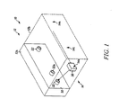
- Fig. 1 is a block diagram of a system in accordance with the invention.
- Fig. 2 is an enlarged diagram illustrating additional aspects of the invention.
- Applicant has recognized that there is a need to be able to modify hydration of electrochemical-type sensors. Modification can take place, in accordance with the invention via various exemplary processes.
- An assumption as to the environmental history of usage a sensor can be made and that sensor can be exposed to a controlled RH environment that is deemed appropriate for the respective history.
- a measurement can be made of one or more parameters which indicate the state of humidity of the sensor, and the sensor can then be exposed to an appropriate RH environment. Multiple measurements could of course be made during the course of exposure to the environment.
- information can be collected during operation of the sensor to subsequently determine the appropriate remedial RH environment.
- electrochemical gas sensors can be hydrated or dehydrated after use to adjust the sensor's electrolyte concentration to a predetermined range. This process can be conveniently carried out when the respective sensor, or associated detector is receiving routine service or battery charging. In this regard, those of skill will understand that either the entire detector or the sensor element alone could be exposed to a hydrating/dehydrating environment.
- Electrolyte adjustment can be implemented by exposing the sensor to water vapor, to moving streams of mixed wet or dry air, exposing the sensor to solid dryers or any other way which provides the desired hydration or dehydration.
- Effective electrolyte adjustment can include adjusting the electrolyte to its allowable operable range.
- Those of skill in the art will recognize that it is not necessary to readjust the respective sensor to its original, out the factory door condition, in view of that fact that electrolytes for such sensors are usually chosen partly on the basis that they continue to function adequately across as wide a range as possible.
- an open loop hydrating/dehydrating methodology could be developed which could be applied to a plurality of cells which have been exposed to the common environment.
- an electrochemical gas sensor component within a gas detector is hydrated, or dehydrated, through modification of the local humidity external to the sensor, while the detector, or, instrument is not in use.
- hydration, or dehydration could take place while the batteries of the detector are being re-charged.
- the present method would replenish or extract an equivalent amount of water vapor to that lost/gained by the sensor during a period of operation, thereby significantly reducing or eliminating environmental effects on sensor performance.
- the detector can be placed in a sealed chamber in which the local humidity is modified/controlled in a fixed or dynamic fashion so as to restore the electrolyte concentration within the sensor to the manufacturer's intended composition.
- the relative humidity, RH of the modified instrument environment may be static and set at an appropriate level to compensate for the working conditions of the instrument/cell, or the modified RH environment may be dynamic and capable of being changed or controlled to an optimum level.
- the optimum level may be determined by measurement of a physical characteristic of the cell that varies with degree of hydration of the electrolyte. For example, pH of the electrolyte could be measured as an indicator of hydration.
- a shroud/jacket can provide an interface with a detector's front panel to provide a seal against the external environment.
- the seal can be maintained with respect to the detector, or sensor element, using a variety of different types of seals such as O-rings, a gasket material, or a molded rubber insert.
- the jacket can contain a salt solution, water or other hydrating solution, whose temperature is/can be controlled via a heater element.
- the jacket can also include a vapor permeable membrane through which moisture vapor can pass into an air space enclosed between the instrument sensor and the shroud. Suitable materials for the membrane material include micro-porous polymers such as PTFE or polyethylene.
- the shroud containing the solution could include an aperture to enable replenishment of lost water.
- various embodiments include:
- the shroud can contain a salt solution with an RH between 5 and 95% RH that is non-temperature controlled.
- the imposed RH would be in the range 40 to 60% to match that of the original electrolyte solution within the cell.
- the RH of the shroud could be chosen and adjusted to compensate for the local working environment. For example. If the cells have been operating in a dry warm environment then a shroud might be chosen to provide a high RH environment to compensate for higher than average loss of water vapor from the cell and vice versa.
- the applied RH% may be controlled by varying the temperature of the salt solution via a heater element.
- the temperature and applied humidity might be specifically controlled and adjusted to an optimum level by measuring a characteristic of the cell that varies with degree of electrolyte hydration. Examples include electrolyte pH, cell capacitance, impedance, or noise. Alternately, cell response to an applied current or voltage pulse can be sensed.
- the local RH environment of the instrument/cell could be modified remotely, provided the instrument is in an enclosed chamber.
- other suitable methods might be to blend two air streams of differing humidity to a single flow of a specific humidity.
- FIG. 1 illustrates an apparatus 10 which embodies the invention.
- a hydrating housing 12 can partially, via section 12a, or fully, as illustrated by expansion section 12b (in phantom), provide a hydrating/dehydrating environment for a plurality of electrochemical gas detectors 14, having members 14a, 14b....14n. Electrolyte adjustment can take place while a battery of the respective detector, such as detector 14i is being recharged.
- detector 14i is illustrated positioned adjacent to section 12a to be hydrated.
- Detector 14i includes, for example, a sensor component 20 having a cylindrically extending portion 22 with an environmental access aperture 24.
- An electrochemical sensing element 26 is carried within the portion 22 exposed to the environment via aperture 24.
- the detector 14i will also include other conventional elements which need not be illustrated here.
- Apparatus 12a includes a housing section 30 with a cylindrical, hollow, protruding member, or jacket, 32.
- Member 32 has an interior peripheral surface 32a, and also carries a seal 34, for example an O ring or other type of seal such as a gasket or molded insert.
- the jacket 32 contains, for example, a salt solution 36 whose temperature is/can be controlled via a heater element 40.
- the heater element 40 can be energized from an exterior source via a connector 42. It will be understood that other solutions could be used to carry out a hydrating or dehydrating process.
- the apparatus 12a also contains a vapor permeable membrane 38 through which moisture vapor can pass into an air space 44 sandwiched between the sensor element 26 and the jacket 32.
- Suitable materials for the membrane's material include micro-porous polymers such as PTFE or polyethylene.
- the apparatus 12a containing the salt solution 36 has an aperture 44 usable to replace lost water.
- detector 14i can be removed from apparatus 12a and placed back into service. On removal, the sensor element 26 should exhibit improved operational characteristics.
Abstract
Description
- The invention pertains to electrochemical gas sensors. More particularly, the invention pertains to devices and methods to adjust levels of hydration in such sensors subsequent to exposure to an ambient environment.
- Electrochemical gas sensors of the type that are commonly used in portable and fixed instrumentation are frequently employed in diverse and sometimes extreme operating environments. Most sensors would be expected to function continuously at temperatures between -20 degrees C to 40 degrees C and 15% to 85% ambient humidity, and intermittently at even more extreme conditions.
- Operating electrochemical cells at the extremes of the their respective operating range for extended periods of time can lead to performance degradation as the internal electrolyte composition responds to the external environmental conditions. For example such cells may lose or gain water in response to their respective working environments.
- The recent trends towards smaller cell package size means that cell performance is even more susceptible to extremes of environmental conditions. Under continued operation this might result in significant degradation in cell performance or even failure.
- There thus continues to be a need for systems and methods which support gas sensor operability at or in extreme external environmental conditions. Preferably, such enhanced operability could be provided relative to known types of electrochemical gas sensors.
-
Fig. 1 is a block diagram of a system in accordance with the invention; and -
Fig. 2 is an enlarged diagram illustrating additional aspects of the invention. - While embodiments of this invention can take many different forms, specific embodiments thereof are shown in the drawings and will be described herein in detail with the understanding that the present disclosure is to be considered as an exemplification of the principles of the invention, as well as the best mode of practicing same, and is not intended to limit the invention to the specific embodiment illustrated.
- Applicant has recognized that there is a need to be able to modify hydration of electrochemical-type sensors. Modification can take place, in accordance with the invention via various exemplary processes. An assumption as to the environmental history of usage a sensor can be made and that sensor can be exposed to a controlled RH environment that is deemed appropriate for the respective history. Alternately, a measurement can be made of one or more parameters which indicate the state of humidity of the sensor, and the sensor can then be exposed to an appropriate RH environment. Multiple measurements could of course be made during the course of exposure to the environment. In yet another alternate, information can be collected during operation of the sensor to subsequently determine the appropriate remedial RH environment.
- In accordance with the invention electrochemical gas sensors can be hydrated or dehydrated after use to adjust the sensor's electrolyte concentration to a predetermined range. This process can be conveniently carried out when the respective sensor, or associated detector is receiving routine service or battery charging. In this regard, those of skill will understand that either the entire detector or the sensor element alone could be exposed to a hydrating/dehydrating environment.
- Electrolyte adjustment can be implemented by exposing the sensor to water vapor, to moving streams of mixed wet or dry air, exposing the sensor to solid dryers or any other way which provides the desired hydration or dehydration.
- Effective electrolyte adjustment can include adjusting the electrolyte to its allowable operable range. Those of skill in the art will recognize that it is not necessary to readjust the respective sensor to its original, out the factory door condition, in view of that fact that electrolytes for such sensors are usually chosen partly on the basis that they continue to function adequately across as wide a range as possible. In addition, where cells have been exposed to a common environment, an open loop hydrating/dehydrating methodology could be developed which could be applied to a plurality of cells which have been exposed to the common environment.
- In a preferred method of practicing the invention, an electrochemical gas sensor component within a gas detector is hydrated, or dehydrated, through modification of the local humidity external to the sensor, while the detector, or, instrument is not in use. For example, hydration, or dehydration, could take place while the batteries of the detector are being re-charged. In accordance herewith, the present method would replenish or extract an equivalent amount of water vapor to that lost/gained by the sensor during a period of operation, thereby significantly reducing or eliminating environmental effects on sensor performance.
- In one aspect, the detector can be placed in a sealed chamber in which the local humidity is modified/controlled in a fixed or dynamic fashion so as to restore the electrolyte concentration within the sensor to the manufacturer's intended composition. The relative humidity, RH of the modified instrument environment may be static and set at an appropriate level to compensate for the working conditions of the instrument/cell, or the modified RH environment may be dynamic and capable of being changed or controlled to an optimum level.
- The optimum level may be determined by measurement of a physical characteristic of the cell that varies with degree of hydration of the electrolyte. For example, pH of the electrolyte could be measured as an indicator of hydration.
- In a disclosed embodiment, a shroud/jacket can provide an interface with a detector's front panel to provide a seal against the external environment. The seal can be maintained with respect to the detector, or sensor element, using a variety of different types of seals such as O-rings, a gasket material, or a molded rubber insert.
- The jacket can contain a salt solution, water or other hydrating solution, whose temperature is/can be controlled via a heater element. The jacket can also include a vapor permeable membrane through which moisture vapor can pass into an air space enclosed between the instrument sensor and the shroud. Suitable materials for the membrane material include micro-porous polymers such as PTFE or polyethylene. The shroud containing the solution could include an aperture to enable replenishment of lost water.
- In accordance with the above, various embodiments include:
- I) Configuring the shroud/Jacket so that it will totally enclose the instrument.
- II) Using the shroud to enclose multiple instruments.
- III) Providing a saturated salt solution in the shroud.
- IV) Providing an unsaturated solution in the shroud.
- V) The shroud can contain a salt solution with an RH between 5 and 95% RH that is non-temperature controlled. Preferably, the imposed RH would be in the
range 40 to 60% to match that of the original electrolyte solution within the cell. However, the RH of the shroud could be chosen and adjusted to compensate for the local working environment. For example. If the cells have been operating in a dry warm environment then a shroud might be chosen to provide a high RH environment to compensate for higher than average loss of water vapor from the cell and vice versa. - VI) The applied RH% may be controlled by varying the temperature of the salt solution via a heater element.
- VII) The temperature and applied humidity might be specifically controlled and adjusted to an optimum level by measuring a characteristic of the cell that varies with degree of electrolyte hydration. Examples include electrolyte pH, cell capacitance, impedance, or noise. Alternately, cell response to an applied current or voltage pulse can be sensed.
- VIII) The local RH environment of the instrument/cell could be modified remotely, provided the instrument is in an enclosed chamber. In addition to the above, other suitable methods might be to blend two air streams of differing humidity to a single flow of a specific humidity.
-
Fig. 1 illustrates an apparatus 10 which embodies the invention. A hydratinghousing 12 can partially, viasection 12a, or fully, as illustrated by expansion section 12b (in phantom), provide a hydrating/dehydrating environment for a plurality ofelectrochemical gas detectors 14, having members 14a, 14b....14n. Electrolyte adjustment can take place while a battery of the respective detector, such asdetector 14i is being recharged. - In
Fig. 2 detector 14i is illustrated positioned adjacent tosection 12a to be hydrated.Detector 14i includes, for example, asensor component 20 having a cylindrically extendingportion 22 with anenvironmental access aperture 24. - An
electrochemical sensing element 26 is carried within theportion 22 exposed to the environment viaaperture 24. Those of skill will understand that thedetector 14i will also include other conventional elements which need not be illustrated here. -
Apparatus 12a includes ahousing section 30 with a cylindrical, hollow, protruding member, or jacket, 32.Member 32 has an interiorperipheral surface 32a, and also carries aseal 34, for example an O ring or other type of seal such as a gasket or molded insert. - When
detector 14i is positioned against theseal 34, the external environment is excluded and the electrolyte of thesensor element 26 can be adjusted byapparatus 12a. - The
jacket 32 contains, for example, asalt solution 36 whose temperature is/can be controlled via aheater element 40. Theheater element 40 can be energized from an exterior source via aconnector 42. It will be understood that other solutions could be used to carry out a hydrating or dehydrating process. - The
apparatus 12a also contains a vaporpermeable membrane 38 through which moisture vapor can pass into anair space 44 sandwiched between thesensor element 26 and thejacket 32. Suitable materials for the membrane's material include micro-porous polymers such as PTFE or polyethylene. Theapparatus 12a containing thesalt solution 36 has anaperture 44 usable to replace lost water. - Once a suitable period of time has elapsed,
detector 14i can be removed fromapparatus 12a and placed back into service. On removal, thesensor element 26 should exhibit improved operational characteristics. - From the foregoing, it will be observed that numerous variations and modifications may be effected without departing from the spirit and scope of the invention. It is to be understood that no limitation with respect to the specific apparatus illustrated herein is intended or should be inferred. It is, of course, intended to cover by the appended claims all such modifications as fall within the scope of the claims.
Claims (15)
- A humidity control apparatus comprising:a housing which defines, at least in part, an interior region and, a second closed region;a vapor permeable membrane between at least a portion of the two regions; anda heating element carried adjacent to the second region.
- An apparatus as in claim 1 where portions of the interior region carry an externally accessible deformable seal.
- An apparatus as in claim 1 or claim 2 where the housing includes a side wall that, at least in part, bounds the interior region.
- An apparatus as in claim 3 where the side wall includes a peripheral surface, adjacent to part of the interior region, the peripheral surface having a closed cross-section.
- An apparatus as in claim 4 where the closed cross-section is one of at least partly curved, or, partly linear.
- An apparatus as in claim 5 where the membrane is oriented so as to be substantially parallel to a plane that includes the cross-section.
- An apparatus as in claim 5 where the side wall extends generally parallel to a line normal to at least a portion of the membrane.
- An apparatus as in claim 7 where the side wall has first and second ends with one end terminating adjacent to the membrane, and the other displaced therefrom in a direction along the line normal thereto.
- An apparatus as in any of the preceding claims which includes at least one of an electrical connector for the heating element, and, a fill port for the second region.
- An apparatus as in any of the preceding claims where the interior region of the housing substantially encloses a selected gas detecting member.
- A method comprising:enclosing at least a gas inflow port of a sensor within a substantially closed volume; andadjusting a hydration parameter of the sensor in accordance with a predetermined criteria.
- A method as in claim 11 where adjusting includes one of:infusing water into the sensor, or, removing water from the sensor via the inflow port of the sensor.
- A method as in claim 11 or claim 12 which includes sealing the volume around the port.
- A method as in claim 12 or claim 13 which includes heating water to enhance infusing into the sensor.
- A method as in claim 14 which includes coupling electrical energy to heat the water, or providing a heating element and a supply of water to be heated to provide the water vapor.
Applications Claiming Priority (1)
| Application Number | Priority Date | Filing Date | Title |
|---|---|---|---|
| US11/872,392 US8741120B2 (en) | 2007-10-15 | 2007-10-15 | Humidity control apparatus for electrochemical sensors |
Publications (2)
| Publication Number | Publication Date |
|---|---|
| EP2051068A2 true EP2051068A2 (en) | 2009-04-22 |
| EP2051068A3 EP2051068A3 (en) | 2010-01-13 |
Family
ID=40229974
Family Applications (1)
| Application Number | Title | Priority Date | Filing Date |
|---|---|---|---|
| EP08166531A Withdrawn EP2051068A3 (en) | 2007-10-15 | 2008-10-14 | Humidity Control Apparatus for Electrochemical Sensors |
Country Status (3)
| Country | Link |
|---|---|
| US (1) | US8741120B2 (en) |
| EP (1) | EP2051068A3 (en) |
| CA (1) | CA2640255A1 (en) |
Cited By (1)
| Publication number | Priority date | Publication date | Assignee | Title |
|---|---|---|---|---|
| EP3006077A4 (en) * | 2013-05-29 | 2017-05-24 | Hisamitsu Pharmaceutical Co., Inc. | System for manufacturing microneedle preparation, and air-conditioning method |
Families Citing this family (3)
| Publication number | Priority date | Publication date | Assignee | Title |
|---|---|---|---|---|
| CN107250785B (en) | 2015-02-02 | 2020-06-05 | 开利公司 | Refrigerant analyzer and method of use |
| EP3371569B1 (en) * | 2015-11-06 | 2021-01-20 | 3M Innovative Properties Company | Gas sensor with a sealable sampling chamber |
| JP7325006B2 (en) * | 2018-03-30 | 2023-08-14 | パナソニックIpマネジメント株式会社 | Gas component measuring device |
Family Cites Families (10)
| Publication number | Priority date | Publication date | Assignee | Title |
|---|---|---|---|---|
| GB1296156A (en) | 1970-07-21 | 1972-11-15 | ||
| JPS5345242A (en) | 1976-10-05 | 1978-04-22 | Mitsubishi Electric Corp | Humidity controller |
| US4265714A (en) * | 1980-03-24 | 1981-05-05 | General Electric Company | Gas sensing and measuring device and process using catalytic graphite sensing electrode |
| US4635467A (en) * | 1985-05-22 | 1987-01-13 | American Hospital Supply Corporation | Calibration cell for the calibration of gaseous or non-gaseous fluid constituent sensors |
| JPH0517650Y2 (en) * | 1986-01-31 | 1993-05-12 | ||
| US4921642A (en) * | 1987-12-03 | 1990-05-01 | Puritan-Bennett Corporation | Humidifier module for use in a gas humidification assembly |
| FI82147C (en) * | 1988-10-27 | 1991-01-10 | Vaisala Oy | CONTROL UNIT FUKTMAETARE FOER FAELTBRUK. |
| FI99164C (en) * | 1994-04-15 | 1997-10-10 | Vaisala Oy | Method for measuring the dew point or gas content and equipment for predicting freezing |
| JP2005214685A (en) | 2004-01-28 | 2005-08-11 | Nec Kansai Ltd | Gas leak detector |
| WO2006138287A2 (en) * | 2005-06-13 | 2006-12-28 | Sigma Systems Corporation | Methods and apparatus for optimizing environmental humidity |
-
2007
- 2007-10-15 US US11/872,392 patent/US8741120B2/en not_active Expired - Fee Related
-
2008
- 2008-10-02 CA CA002640255A patent/CA2640255A1/en not_active Abandoned
- 2008-10-14 EP EP08166531A patent/EP2051068A3/en not_active Withdrawn
Non-Patent Citations (1)
| Title |
|---|
| None |
Cited By (2)
| Publication number | Priority date | Publication date | Assignee | Title |
|---|---|---|---|---|
| EP3006077A4 (en) * | 2013-05-29 | 2017-05-24 | Hisamitsu Pharmaceutical Co., Inc. | System for manufacturing microneedle preparation, and air-conditioning method |
| US11130148B2 (en) | 2013-05-29 | 2021-09-28 | Hisamitsu Pharmaceutical Co., Inc. | System for manufacturing microneedle preparation, and air-conditioning method |
Also Published As
| Publication number | Publication date |
|---|---|
| US8741120B2 (en) | 2014-06-03 |
| EP2051068A3 (en) | 2010-01-13 |
| CA2640255A1 (en) | 2009-04-15 |
| US20090095640A1 (en) | 2009-04-16 |
Similar Documents
| Publication | Publication Date | Title |
|---|---|---|
| US8741120B2 (en) | Humidity control apparatus for electrochemical sensors | |
| CN103608673A (en) | Apparatus for measuring perviousness to water vapor | |
| EP3183566B1 (en) | Automated self-compensation apparatus and method for providing electro-chemical sensors | |
| CN115236135B (en) | Baseline calibration method for gas sensor, control device and gas sensor | |
| JP5159992B2 (en) | Moisture concentration detector | |
| JP3462854B2 (en) | Airtightness inspection method and airtightness inspection device for closed space with water vapor transfer control device | |
| EP3254097A1 (en) | Refrigerant analyzer and a method of using the same | |
| US7854159B2 (en) | Sensor and methods for measuring of concentrations of components in a liquid | |
| KR102301888B1 (en) | Temperature conpensation method for calibrating of gas sensor module using change of heater current | |
| US20200300710A1 (en) | Systems and methods for logging data in harsh environments | |
| JP5464694B2 (en) | Capacitive humidity sensor | |
| KR20200063999A (en) | Ambient sensor with actuator | |
| US10145771B2 (en) | Method, device and computer medium for determining the density of liquids | |
| CN109959692A (en) | Measurement probe for electrochemical measurement | |
| EP3519801A1 (en) | Hydrophobic and oleophobic cover for gas sensing module | |
| CN115407017A (en) | Calibration method for gas detection device and gas detection device | |
| Enfield et al. | Conductivity instrumentation for in situ measurement of soil salinity | |
| US8720255B2 (en) | Water uptake measurement system | |
| JP7348096B2 (en) | Gas concentration measuring device | |
| JP2005084018A (en) | Humidity conditioning cell and high sensitivity gas sensor | |
| JPS6011160A (en) | Moisture analysis meter | |
| JP2012037347A (en) | Flood detection method | |
| JP2005214685A (en) | Gas leak detector | |
| BRPI0910085B1 (en) | gaseous atmosphere control system for inert gas for electrical power transformers with liquid insulators | |
| CN213336520U (en) | Waterproof temperature sensor of ventilative formula |
Legal Events
| Date | Code | Title | Description |
|---|---|---|---|
| PUAI | Public reference made under article 153(3) epc to a published international application that has entered the european phase |
Free format text: ORIGINAL CODE: 0009012 |
|
| AK | Designated contracting states |
Kind code of ref document: A2 Designated state(s): AT BE BG CH CY CZ DE DK EE ES FI FR GB GR HR HU IE IS IT LI LT LU LV MC MT NL NO PL PT RO SE SI SK TR |
|
| AX | Request for extension of the european patent |
Extension state: AL BA MK RS |
|
| RAP1 | Party data changed (applicant data changed or rights of an application transferred) |
Owner name: LIFE SAFETY DISTRIBUTION AG |
|
| PUAL | Search report despatched |
Free format text: ORIGINAL CODE: 0009013 |
|
| AK | Designated contracting states |
Kind code of ref document: A3 Designated state(s): AT BE BG CH CY CZ DE DK EE ES FI FR GB GR HR HU IE IS IT LI LT LU LV MC MT NL NO PL PT RO SE SI SK TR |
|
| AX | Request for extension of the european patent |
Extension state: AL BA MK RS |
|
| RIC1 | Information provided on ipc code assigned before grant |
Ipc: G01N 33/00 20060101ALI20091208BHEP Ipc: G01N 27/28 20060101AFI20090120BHEP |
|
| 17P | Request for examination filed |
Effective date: 20100702 |
|
| 17Q | First examination report despatched |
Effective date: 20100730 |
|
| AKX | Designation fees paid |
Designated state(s): DE GB |
|
| STAA | Information on the status of an ep patent application or granted ep patent |
Free format text: STATUS: THE APPLICATION IS DEEMED TO BE WITHDRAWN |
|
| 18D | Application deemed to be withdrawn |
Effective date: 20170503 |