EP2050940A1 - Method of manufacturing multi-stage supercharging exhaust turbosupercharger - Google Patents
Method of manufacturing multi-stage supercharging exhaust turbosupercharger Download PDFInfo
- Publication number
- EP2050940A1 EP2050940A1 EP07792323A EP07792323A EP2050940A1 EP 2050940 A1 EP2050940 A1 EP 2050940A1 EP 07792323 A EP07792323 A EP 07792323A EP 07792323 A EP07792323 A EP 07792323A EP 2050940 A1 EP2050940 A1 EP 2050940A1
- Authority
- EP
- European Patent Office
- Prior art keywords
- pressure
- low
- stage turbocharger
- turbocharger
- pressure stage
- Prior art date
- Legal status (The legal status is an assumption and is not a legal conclusion. Google has not performed a legal analysis and makes no representation as to the accuracy of the status listed.)
- Granted
Links
- 238000004519 manufacturing process Methods 0.000 title claims abstract description 10
- 239000000470 constituent Substances 0.000 claims abstract description 8
- 238000005266 casting Methods 0.000 claims description 7
- 238000003466 welding Methods 0.000 claims description 7
- 238000002485 combustion reaction Methods 0.000 claims description 5
- 238000000034 method Methods 0.000 claims description 4
- 230000003247 decreasing effect Effects 0.000 description 7
- 229910052751 metal Inorganic materials 0.000 description 4
- 239000002184 metal Substances 0.000 description 4
- 238000010276 construction Methods 0.000 description 3
- 238000007789 sealing Methods 0.000 description 2
- 229920001875 Ebonite Polymers 0.000 description 1
- 229910000831 Steel Inorganic materials 0.000 description 1
- 229910052782 aluminium Inorganic materials 0.000 description 1
- XAGFODPZIPBFFR-UHFFFAOYSA-N aluminium Chemical compound [Al] XAGFODPZIPBFFR-UHFFFAOYSA-N 0.000 description 1
- 238000009434 installation Methods 0.000 description 1
- 239000000463 material Substances 0.000 description 1
- 238000005058 metal casting Methods 0.000 description 1
- 239000007769 metal material Substances 0.000 description 1
- 230000002093 peripheral effect Effects 0.000 description 1
- 229920005989 resin Polymers 0.000 description 1
- 239000011347 resin Substances 0.000 description 1
- 239000010959 steel Substances 0.000 description 1
Images


Classifications
-
- F—MECHANICAL ENGINEERING; LIGHTING; HEATING; WEAPONS; BLASTING
- F02—COMBUSTION ENGINES; HOT-GAS OR COMBUSTION-PRODUCT ENGINE PLANTS
- F02B—INTERNAL-COMBUSTION PISTON ENGINES; COMBUSTION ENGINES IN GENERAL
- F02B39/00—Component parts, details, or accessories relating to, driven charging or scavenging pumps, not provided for in groups F02B33/00 - F02B37/00
-
- F—MECHANICAL ENGINEERING; LIGHTING; HEATING; WEAPONS; BLASTING
- F01—MACHINES OR ENGINES IN GENERAL; ENGINE PLANTS IN GENERAL; STEAM ENGINES
- F01D—NON-POSITIVE DISPLACEMENT MACHINES OR ENGINES, e.g. STEAM TURBINES
- F01D25/00—Component parts, details, or accessories, not provided for in, or of interest apart from, other groups
- F01D25/24—Casings; Casing parts, e.g. diaphragms, casing fastenings
-
- F—MECHANICAL ENGINEERING; LIGHTING; HEATING; WEAPONS; BLASTING
- F01—MACHINES OR ENGINES IN GENERAL; ENGINE PLANTS IN GENERAL; STEAM ENGINES
- F01D—NON-POSITIVE DISPLACEMENT MACHINES OR ENGINES, e.g. STEAM TURBINES
- F01D25/00—Component parts, details, or accessories, not provided for in, or of interest apart from, other groups
- F01D25/28—Supporting or mounting arrangements, e.g. for turbine casing
-
- F—MECHANICAL ENGINEERING; LIGHTING; HEATING; WEAPONS; BLASTING
- F01—MACHINES OR ENGINES IN GENERAL; ENGINE PLANTS IN GENERAL; STEAM ENGINES
- F01D—NON-POSITIVE DISPLACEMENT MACHINES OR ENGINES, e.g. STEAM TURBINES
- F01D9/00—Stators
- F01D9/02—Nozzles; Nozzle boxes; Stator blades; Guide conduits, e.g. individual nozzles
- F01D9/026—Scrolls for radial machines or engines
-
- F—MECHANICAL ENGINEERING; LIGHTING; HEATING; WEAPONS; BLASTING
- F01—MACHINES OR ENGINES IN GENERAL; ENGINE PLANTS IN GENERAL; STEAM ENGINES
- F01N—GAS-FLOW SILENCERS OR EXHAUST APPARATUS FOR MACHINES OR ENGINES IN GENERAL; GAS-FLOW SILENCERS OR EXHAUST APPARATUS FOR INTERNAL COMBUSTION ENGINES
- F01N13/00—Exhaust or silencing apparatus characterised by constructional features ; Exhaust or silencing apparatus, or parts thereof, having pertinent characteristics not provided for in, or of interest apart from, groups F01N1/00 - F01N5/00, F01N9/00, F01N11/00
- F01N13/08—Other arrangements or adaptations of exhaust conduits
- F01N13/10—Other arrangements or adaptations of exhaust conduits of exhaust manifolds
-
- F—MECHANICAL ENGINEERING; LIGHTING; HEATING; WEAPONS; BLASTING
- F01—MACHINES OR ENGINES IN GENERAL; ENGINE PLANTS IN GENERAL; STEAM ENGINES
- F01N—GAS-FLOW SILENCERS OR EXHAUST APPARATUS FOR MACHINES OR ENGINES IN GENERAL; GAS-FLOW SILENCERS OR EXHAUST APPARATUS FOR INTERNAL COMBUSTION ENGINES
- F01N13/00—Exhaust or silencing apparatus characterised by constructional features ; Exhaust or silencing apparatus, or parts thereof, having pertinent characteristics not provided for in, or of interest apart from, groups F01N1/00 - F01N5/00, F01N9/00, F01N11/00
- F01N13/18—Construction facilitating manufacture, assembly, or disassembly
-
- F—MECHANICAL ENGINEERING; LIGHTING; HEATING; WEAPONS; BLASTING
- F02—COMBUSTION ENGINES; HOT-GAS OR COMBUSTION-PRODUCT ENGINE PLANTS
- F02B—INTERNAL-COMBUSTION PISTON ENGINES; COMBUSTION ENGINES IN GENERAL
- F02B37/00—Engines characterised by provision of pumps driven at least for part of the time by exhaust
- F02B37/013—Engines characterised by provision of pumps driven at least for part of the time by exhaust with exhaust-driven pumps arranged in series
-
- F—MECHANICAL ENGINEERING; LIGHTING; HEATING; WEAPONS; BLASTING
- F02—COMBUSTION ENGINES; HOT-GAS OR COMBUSTION-PRODUCT ENGINE PLANTS
- F02B—INTERNAL-COMBUSTION PISTON ENGINES; COMBUSTION ENGINES IN GENERAL
- F02B37/00—Engines characterised by provision of pumps driven at least for part of the time by exhaust
- F02B37/02—Gas passages between engine outlet and pump drive, e.g. reservoirs
-
- F—MECHANICAL ENGINEERING; LIGHTING; HEATING; WEAPONS; BLASTING
- F02—COMBUSTION ENGINES; HOT-GAS OR COMBUSTION-PRODUCT ENGINE PLANTS
- F02B—INTERNAL-COMBUSTION PISTON ENGINES; COMBUSTION ENGINES IN GENERAL
- F02B37/00—Engines characterised by provision of pumps driven at least for part of the time by exhaust
- F02B37/12—Control of the pumps
- F02B37/16—Control of the pumps by bypassing charging air
- F02B37/162—Control of the pumps by bypassing charging air by bypassing, e.g. partially, intake air from pump inlet to pump outlet
-
- F—MECHANICAL ENGINEERING; LIGHTING; HEATING; WEAPONS; BLASTING
- F02—COMBUSTION ENGINES; HOT-GAS OR COMBUSTION-PRODUCT ENGINE PLANTS
- F02C—GAS-TURBINE PLANTS; AIR INTAKES FOR JET-PROPULSION PLANTS; CONTROLLING FUEL SUPPLY IN AIR-BREATHING JET-PROPULSION PLANTS
- F02C6/00—Plural gas-turbine plants; Combinations of gas-turbine plants with other apparatus; Adaptations of gas-turbine plants for special use
- F02C6/04—Gas-turbine plants providing heated or pressurised working fluid for other apparatus, e.g. without mechanical power output
- F02C6/10—Gas-turbine plants providing heated or pressurised working fluid for other apparatus, e.g. without mechanical power output supplying working fluid to a user, e.g. a chemical process, which returns working fluid to a turbine of the plant
- F02C6/12—Turbochargers, i.e. plants for augmenting mechanical power output of internal-combustion piston engines by increase of charge pressure
-
- F—MECHANICAL ENGINEERING; LIGHTING; HEATING; WEAPONS; BLASTING
- F02—COMBUSTION ENGINES; HOT-GAS OR COMBUSTION-PRODUCT ENGINE PLANTS
- F02B—INTERNAL-COMBUSTION PISTON ENGINES; COMBUSTION ENGINES IN GENERAL
- F02B37/00—Engines characterised by provision of pumps driven at least for part of the time by exhaust
- F02B37/12—Control of the pumps
- F02B37/18—Control of the pumps by bypassing exhaust from the inlet to the outlet of turbine or to the atmosphere
-
- F—MECHANICAL ENGINEERING; LIGHTING; HEATING; WEAPONS; BLASTING
- F05—INDEXING SCHEMES RELATING TO ENGINES OR PUMPS IN VARIOUS SUBCLASSES OF CLASSES F01-F04
- F05D—INDEXING SCHEME FOR ASPECTS RELATING TO NON-POSITIVE-DISPLACEMENT MACHINES OR ENGINES, GAS-TURBINES OR JET-PROPULSION PLANTS
- F05D2230/00—Manufacture
- F05D2230/60—Assembly methods
-
- Y—GENERAL TAGGING OF NEW TECHNOLOGICAL DEVELOPMENTS; GENERAL TAGGING OF CROSS-SECTIONAL TECHNOLOGIES SPANNING OVER SEVERAL SECTIONS OF THE IPC; TECHNICAL SUBJECTS COVERED BY FORMER USPC CROSS-REFERENCE ART COLLECTIONS [XRACs] AND DIGESTS
- Y02—TECHNOLOGIES OR APPLICATIONS FOR MITIGATION OR ADAPTATION AGAINST CLIMATE CHANGE
- Y02T—CLIMATE CHANGE MITIGATION TECHNOLOGIES RELATED TO TRANSPORTATION
- Y02T10/00—Road transport of goods or passengers
- Y02T10/10—Internal combustion engine [ICE] based vehicles
- Y02T10/12—Improving ICE efficiencies
-
- Y—GENERAL TAGGING OF NEW TECHNOLOGICAL DEVELOPMENTS; GENERAL TAGGING OF CROSS-SECTIONAL TECHNOLOGIES SPANNING OVER SEVERAL SECTIONS OF THE IPC; TECHNICAL SUBJECTS COVERED BY FORMER USPC CROSS-REFERENCE ART COLLECTIONS [XRACs] AND DIGESTS
- Y10—TECHNICAL SUBJECTS COVERED BY FORMER USPC
- Y10T—TECHNICAL SUBJECTS COVERED BY FORMER US CLASSIFICATION
- Y10T29/00—Metal working
- Y10T29/49—Method of mechanical manufacture
- Y10T29/49229—Prime mover or fluid pump making
- Y10T29/49231—I.C. [internal combustion] engine making
- Y10T29/49234—Rotary or radial engine making
-
- Y—GENERAL TAGGING OF NEW TECHNOLOGICAL DEVELOPMENTS; GENERAL TAGGING OF CROSS-SECTIONAL TECHNOLOGIES SPANNING OVER SEVERAL SECTIONS OF THE IPC; TECHNICAL SUBJECTS COVERED BY FORMER USPC CROSS-REFERENCE ART COLLECTIONS [XRACs] AND DIGESTS
- Y10—TECHNICAL SUBJECTS COVERED BY FORMER USPC
- Y10T—TECHNICAL SUBJECTS COVERED BY FORMER US CLASSIFICATION
- Y10T29/00—Metal working
- Y10T29/49—Method of mechanical manufacture
- Y10T29/49316—Impeller making
- Y10T29/4932—Turbomachine making
- Y10T29/49321—Assembling individual fluid flow interacting members, e.g., blades, vanes, buckets, on rotary support member
-
- Y—GENERAL TAGGING OF NEW TECHNOLOGICAL DEVELOPMENTS; GENERAL TAGGING OF CROSS-SECTIONAL TECHNOLOGIES SPANNING OVER SEVERAL SECTIONS OF THE IPC; TECHNICAL SUBJECTS COVERED BY FORMER USPC CROSS-REFERENCE ART COLLECTIONS [XRACs] AND DIGESTS
- Y10—TECHNICAL SUBJECTS COVERED BY FORMER USPC
- Y10T—TECHNICAL SUBJECTS COVERED BY FORMER US CLASSIFICATION
- Y10T29/00—Metal working
- Y10T29/49—Method of mechanical manufacture
- Y10T29/49316—Impeller making
- Y10T29/4932—Turbomachine making
- Y10T29/49323—Assembling fluid flow directing devices, e.g., stators, diaphragms, nozzles
-
- Y—GENERAL TAGGING OF NEW TECHNOLOGICAL DEVELOPMENTS; GENERAL TAGGING OF CROSS-SECTIONAL TECHNOLOGIES SPANNING OVER SEVERAL SECTIONS OF THE IPC; TECHNICAL SUBJECTS COVERED BY FORMER USPC CROSS-REFERENCE ART COLLECTIONS [XRACs] AND DIGESTS
- Y10—TECHNICAL SUBJECTS COVERED BY FORMER USPC
- Y10T—TECHNICAL SUBJECTS COVERED BY FORMER US CLASSIFICATION
- Y10T29/00—Metal working
- Y10T29/49—Method of mechanical manufacture
- Y10T29/49398—Muffler, manifold or exhaust pipe making
Definitions
- the present invention relates to a method for manufacturing a multistage exhaust turbocharger for an internal combustion engine, the turbocharger comprising a high-pressure stage turbocharger having a high-pressure turbine drivable by exhaust gas from the engine and a low-pressure stage turbocharger having a low-pressure turbine drivable by exhaust gas from the high-pressure turbine, the turbochargers being arranged sequentially in a flow path of the exhaust gas, and supply air for the engine pressurized by a low-pressure compressor of the low-pressure stage turbocharger being supplied via an air supply channel to a high-pressure compressor of the high-pressure stage turbocharger to be further pressurized by the high-pressure compressor.
- multistage (two-stage) exhaust turbo-charging system in which a high-pressure stage turbocharger having a high-pressure turbine drivable by exhaust gas from the exhaust manifold of the engine and a low-pressure stage turbocharger having a low-pressure turbine drivable by exhaust gas from the high-pressure turbine are arranged sequentially in the flow path of the exhaust gas, and supply air for the engine pressurized by a low-pressure compressor of the low-pressure stage turbocharger is supplied via an air supply channel to a high-pressure compressor of the high-pressure stage turbocharger to be further pressurized by the high-pressure compressor and charged to the engine.
- This type of two-stage exhaust turbochargers are known for example from US 2003/0159442 A1 , US 6, 378, 308 B1 and JP 59-82526 .
- the two-stage exhaust turbocharger disclosed in US 2003/0159442 A1 includes a high-pressure stage exhaust turbocharger and a low-pressure stage exhaust turbocharger arranged compactly so that it is applicable to an on-vehicle engine mounted on a narrow engine room of a vehicle.
- the high-pressure stage and low-pressure stage turbochargers are arranged three dimensionally with the rotation axis of each turbocharger parallel to each other, and the exhaust gas outlet side of the turbine of the high pressure stage turbocharger is connected to the exhaust inlet side of the turbine of the low pressure stage turbocharger by an exhaust channel and the supply air outlet side of the compressor of the low pressure stage turbocharger is connected to supply air inlet side of the high pressure stage turbocharger by an air supply channel.
- a comparatively large installation space is required in the engine room to install an engine equipped with a two-stage exhaust turbocharger of this type because it is inevitably increased in bulk as compared with a single-stage one.
- the two-stage exhaust turbocharger disclosed in the patent literature 1 is a one which meets the demand, however, it can be further improved.
- the two-stage turbocharger is mounted compactly by arranging the high pressure stage and low pressure stage turbocharger three dimensionally with the rotation axis of each turbocharger parallel to each other, however, because the exhaust turbines are connected via the exhaust gas channel and the compressors are connected via the air supply channel, two connecting operations are required, which result in increased assembling man-hours.
- the exhaust gas channel in which exhaust gas of high temperature flows
- the exhaust gas channel, gasket, and bolts are required, so number of parts increases.
- connection of the turbochargers are performed by two connecting channels of the exhaust gas channel and air supply channel, volume occupied by the two-stage turbocharger increases, and mounting of an engine equipped with the two-stage exhaust turbocharger in a narrow engine room of a vehicle is not so facilitated.
- the present invention was made in light of the problems in conventional art, and the object is to provide a method of manufacturing a multistage exhaust turbocharger having a high-pressure stage turbocharger and a low-pressure stage turbocharger with a reduced pipe connection between the turbochargers thereby reducing the bulk of the multistage exhaust turbocharger, the number of parts for the connection, and assembling man-hours, and facilitating the mounting of an engine equipped with the multistage exhaust turbocharger in a narrow engine room of a vehicle.
- the present invention proposes a method for manufacturing a multistage exhaust turbocharger for an internal combustion engine including a high-pressure stage turbocharger having a high-pressure turbine drivable by exhaust gas from an exhaust manifold of the engine and a low-pressure stage turbocharger having a low-pressure turbine drivable by exhaust gas flowed out from the high-pressure turbine after driving the turbine, the turbochargers being arranged sequentially in the flow path of the exhaust gas of the engine, supply air for the engine pressurized by a low-pressure compressor of the low-pressure stage turbocharger being supplied via an air supply channel to a high-pressure compressor of the high-pressure stage turbocharger to be further pressurized by the high-pressure compressor, wherein a high-pressure turbine housing of said high-pressure stage turbocharger is formed integral with said exhaust manifold by casting or welding, constituent parts of said high-pressure stage turbocharger are assembled using said high-pressure turbine housing as a reference, then said low-pressure stage turbocharger is attached to said high-pressure
- the high-pressure stage turbocharger includes a high-pressure compressor cover for accommodating the high-pressure compressor and an exhaust gas guide member which is connected to the high-pressure turbine housing at its one end and has a the low-pressure turbine connection flange at its other end side, the high-pressure stage turbocharger and the low-pressure stage turbocharger are connected by connecting the low-pressure turbine housing to the low-pressure turbine connection of the exhaust gas guide member, further a supply air outlet of a low-pressure compressor cover of the low-pressure stage turbocharger and a supply air inlet of the high-pressure compressor cover of the high-pressure stage turbocharger are connected by a supply air channel.
- the exhaust manifold formed integral with the high-pressure turbine housing is attached to one side of the engine
- the low-pressure turbocharger is located below the high-pressure turbocharger at one side of the engine and attached directly to the exhaust gas passage of the high-pressure stage turbocharger
- the compressor sides of the low-pressure stage turbocharger and high-pressure stage turbocharger are connected by the air supply channel, so the multistage exhaust turbocharger is composed on one side of the engine effectively utilizing the space at the one side of the engine.
- the exhaust manifold attached with the high-pressure stage turbocharger is first fastened to the engine and then the low-pressure stage turbocharger is attached to the engine, a relatively light sub-assembly of the exhaust manifold and the relatively small high-pressure stage turbocharger is attached to one side of the engine and then the relatively large and heavy low-pressure stage turbocharger is attached to the sub-assembly already attached to the engine, the attaching operation is facilitated, resulting in decreased man-hours of attaching the two-stage turbocharger to the engine.
- the assembling of the high-pressure turbocharger is facilitated, and by connecting the exhaust turbine sides, where high-pressure high temperature exhaust gas flows, of the high-pressure stage turbocharger and low-pressure stage turbocharger directly by flange connection without using piping as is the case in the prior art, the connecting operation of the two turbochargers is simplified as compared with the prior art, resulting in decreased assembling man-hours of the multistage exhaust turbocharger.
- parts for connecting the exhaust turbine sides such as piping, gaskets, and bolts can be eliminated, and the number of parts is reduced, and as connection of the high-pressure and low-pressure stage turbochargers with piping is reduced to only one, i.e. the connection with the air supply channel 21, as compared with two piping connections of the prior two-stage exhaust turbocharger, bulk of the two-stage exhaust turbocharger device of the invention is reduced and mounting of an engine equipped with the two-stage exhaust turbocharger in a narrow engine room of a vehicle is facilitated.
- the exhaust manifold formed integral with the high-pressure turbine housing is attached to one side of the engine
- the low-pressure turbocharger is located below the high-pressure turbocharger at one side of the engine and attached directly to the exhaust gas passage of the high-pressure stage turbocharger, so the multistage exhaust turbocharger can composed on one side of the engine effectively utilizing the space at the one side of the engine, and as a relatively light sub-assembly of the exhaust manifold and the relatively small high-pressure stage turbocharger is first attached to one side of the engine and then the relatively large and heavy low-pressure stage turbocharger is attached to the sub-assembly already attached to the engine, the attaching operation is facilitated resulting in decreased man-hours.
- FIG.1 is a side elevation showing the total construction of the first embodiment of the two-stage exhaust turbocharger according to the invention
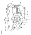
- FIG.2 is a plan view of the first embodiment of FIG.1
- FIG.3 is a sectional view of the first embodiment of FIG.1 along the center line of the rotor shaft of the high-pressure stage turbocharger.
- FIG. 4A is a side elevation showing the turbine housing of the high pressure stage exhaust turbocharger in the second embodiment of the invention
- FIG. 4B is a view in the direction of arrow Y in FIG.4A
- FIG.5 is a view in the direction of arrow W in FIG. 4A
- FIG. 6 is a partially sectional view of the air supply channel indicated by U in FIG.1 .
- reference numeral 1 is a high-pressure stage turbocharger having a high-pressure turbine 1a and a high-pressure compressor 1b connected to the turbine 1a by a high-pressure stage rotor shaft 3;
- 2 is a low-pressure stage turbocharger having a low-pressure turbine 2a and a low-pressure compressor 2b connected to the turbine by a low-pressure stage rotor shaft.
- Reference numeral 10 is a high-pressure turbine housing of the high-pressure stage turbocharger 1; 9 is a high-pressure compressor cover; 11 is an exhaust channel.
- Reference numeral 2s is a low-pressure turbine housing of the low-pressure stage turbocharger 2; 2t is a low-pressure compressor cover.
- Reference numeral 21 is an air supply channel connecting the low-pressure compressor cover 2t to the high-pressure compressor cover 9.
- the air supply channel 21 is detailed later.
- reference numeral 10 is a high-pressure turbine housing 10 of cast metal (may be of welded construction); 1a is a high-pressure turbine of radial flow type; 1b is a high-pressure compressor connected to the turbine 1a; 3 is a high-pressure stage rotor shaft connecting the turbine 1a and the compressor 1b; 9 is a high-pressure compressor made of cast metal; and 6 is a high-pressure stage bearing housing made of cast metal.
- Reference numeral 11 is an exhaust gas guide member made of cast metal, which is connected to a flange (10a indicates its flange face) of the high-pressure turbine housing 10 with the longitudinal center line of the channel coinciding the rotation axis M of the high-pressure turbine 1a by means of a plurality of bolts not shown in the drawing.
- the exhaust gas guide member 11 has a mounting flange 12 for connecting the low-pressure stage turbocharger 2b thereto.
- the mounting flange 12 extends in the direction parallel to the rotation axis M, and the low-pressure turbine housing 2s is connected directly to the flange 12 by means of a plurality of bolts(12z indicates a bolt hole) as shown in FIG.1 .
- Exhaust gas flowing out from the high-pressure turbine 1a is introduced to the entrance of the low-pressure turbine 2a passing through an exhaust gas passage 11s in the exhaust gas guide member 11 to the mounting flange of which is attached the low-pressure turbine 2a.
- the high-pressure compressor cover 9 has a compressor inlet passage 7 to which supply air is introduced from the low-pressure compressor 2b (see FIG. 1 ) via the air supply channel 21 and a bypass inlet passage 8a.
- a switching aperture 5c which is opened and closed by the compressor bypass valve device 5 is formed between the compressor inlet passage 7 and the bypass inlet passage 8a.
- the high-pressure compressor cover 9 has also a bypass outlet pipe part 8 to which the compressor bypass channel 12 is to be connected.
- the bypass outlet pipe part 8 is formed integral with the compressor cover 9 in a form extending in a direction perpendicular to the rotation axis M adjacent a case 53 attached to the compressor cover 9, the compressor bypass valve device 5 being attached to the case 53.
- the compressor bypass valve device 5 includes a compressor bypass valve 51 and an actuator 52, and the switching aperture 5c is closed or opened by allowing the compressor bypass valve 51 to seat on or depart from a valve seat 55 formed on the peripheral part of the switching aperture 5c by reciprocation motion of the actuator to shut off or communicate the compressor inlet passage 7 from or to the bypass inlet passage, thereby shutting off or communicating the compressor inlet passage 7 to or from a compressor bypass channel not shown in the drawing.
- a bypass outlet pipe part 8 is formed integral with the compressor cover 9 in a form extending in a direction perpendicular to the rotation axis M adjacent the compressor bypass valve device 5 installed to the compressor cover 9 as shown in FIG.3 .
- Reference numeral 15 is an EGR flange formed integral with the exhaust gas guide member 11. A part of exhaust gas flowed out from the outlet of the high pressure turbine 1a is extracted from the exhaust gas flowing in the passage 11s and introduced to a supply air inlet pipe(not shown) by a conduit(not shown) attached to the EGR flange as exhaust recirculation gas.
- reference numeral 103 is an exhaust manifold, which is formed integral with the high-pressure turbine housing 10 of the high-pressure stage turbocharger 1 and made by metal casting.
- the exhaust gas guide member 11 is connected to the flange face 10a of the flange 10b of the turbine housing 10 by a plurality of bolts not shown in the drawings with the longitudinal center line of the exhaust gas guide member 11 coinciding the rotation axis M of the high-pressure turbine 1a.
- Reference numeral 103a is a flange of the exhaust manifold 103.
- the flange face 103b of each flange 103a is perpendicular to the flange face 10a of the flange 10b of the high-pressure turbine housing 10, and the exhaust manifold is fixed to the engine via the flanges 103a by means of a plurality of bolts not shown in the drawings.
- Reference numeral 21 is an air supply channel bent to connect the low-pressure compressor cover 2t to the high-pressure compressor cover 9 and made of metal material, such as a steel pipe, and aluminum pipe, or a resin or hard rubber pipe having flexibility.
- the air supply channel 21 has an inlet flange 212 provided at its air inlet side.
- the flange 212 is fixed to the a flange 220 of the low-pressure compressor cover 2t by means of a plurality of bolts 213 with a seal ring 214 placed between the flanges.
- the air supply channel 21 has an outlet flange 215 provided at its air outlet side.
- the outlet flange 215 is fixed to a flange 9z of the high-pressure compressor cover 9 by means of a plurality of bolts 217.
- a protruded part 21y of the air supply channel 21 protruding from the flange 215 is received in a reception hole 9y of the high-pressure compressor cover 9 with an O-ring 216 placed between the protruding part 21y and the hole 9y for the purpose of air sealing.
- a stage control valve not shown in the drawings is closed or its opening is controlled, and an exhaust bypass valve device not shown in the drawings and the compressor bypass valve device 5 are closed.
- both the high-pressure turbine 1a of the high-pressure stage turbocharger 1 and the low-pressure turbine 2a of the low-pressure turbocharger 2 are driven by exhaust gas exhausted from the exhaust manifold 103.
- supply air pressurized by the low-pressure compressor 2b driven by the turbine 2a is further pressurized by the high-pressure compressor 1b driven by the high-pressure turbine 1a, then the pressurized supply air is cooled by an air cooler not shown in the drawings and supplied each of the cylinders of the engine as charge air for combustion in the cylinders.
- Supercharge pressure can be increased to increase engine output by performing two-stage supercharging like this in a low, middle speed operating range of the engine.
- the stage control valve and the compressor bypass valve device 5 are opened and the opening of the exhaust bypass valve device is controlled so that desired pressure of charge air is produced.
- the high-pressure turbine 1a, high-pressure compressor 1b, high-pressure bearing housing 6, high-pressure compressor cover 9, etc. are assembled to the high-pressure turbine housing 10 formed integral with the exhaust manifold 103 by casting or welding to compose the high-pressure stage turbocharger 1 using the flange face 10a of the flange 10b of the high-pressure turbine housing 10 as a reference plane, and the exhaust gas guide member 11 is attached to the flange 10b of by means of a plurality of bolts.
- the low-pressure stage turbocharger 2 comprising the low-pressure turbine 2a, low-pressure compressor 2b, low-pressure turbine casing 2s, low-pressure compressor cover 2t, etc. is assembled, and the low-pressure turbine housing 2s is fastened to the low-pressure turbine mounting flange 12 of the exhaust gas guide member 11 by means of a plurality of bolts (reference numeral 12z indicates a bolt hole).
- the high-pressure stage turbocharger 1 and low-pressure stage turbocharger 2 are connected via the exhaust gas guide member 11.
- the O-ring 216 is attached to the air outlet end parts 21y of the air supply channel 21, the end pars 21y is inserted into the reception hole 9y, and the outlet flange 215 of the air supply channel 21 fastened to the flange 9z of the high-pressure compressor cover 9 are fastened by means of bolts 217. Then, the seal ring 214 is attached to the flange 220 of the low-pressure compressor cover 2t, and the inlet flange 212 of the air supply channel 21 is fastened to the flange 220 of the low-pressure compressor cover 2t.
- the air supply pipe 21 is attached to connect between the high-pressure compressor cover 9 and the low-pressure compressor cover 2t in a state airtight connections are ensured.
- the high-pressure stage turbocharger 1 is assembled by attaching constituent parts of the high pressure stage turbocharger, including high pressure compressor cover 9, to the high-pressure turbine housing 10 which is formed integral with the exhaust manifold 103 by casting or welding, then the exhaust gas guide member 11 is attached to the high-pressure turbine housing 10, and then the low-pressure turbine housing 2s of the low-pressure stage turbocharger 2 is attached to the mounting flange 10 of the exhaust gas guide member 11, so the constituent parts of the high-pressure stage turbocharger 1 can be assembled easily by using the high-pressure turbine housing 10 formed integral with the exhaust manifold 103 as a reference plane, and the low-pressure stage turbocharger 2 is connected to the high-pressure stage turbocharger 1 without using any piping for connecting exhaust gas sides of the turbines such as an exhaust gas channel used in the prior art, and with only one air supply channel 21 connecting between the high-pressure compressor cover 9 and low-pressure compressor cover 2t, which connection being done at the last stage of assembling the turbochargers.
- connection of the turbine sides of the high-pressure stage turbocharger 1 and low-pressure stage turbocharger is facilitated resulting in decreased number of parts for the connection and decreased assembling man-hours as compared with the prior art.
- connection of the high-pressure and low-pressure stage turbochargers with piping is reduced to only one, i.e. the connection with the air supply channel 21, as compared with two piping connections of the prior two-stage exhaust turbocharger, bulk of the two-stage exhaust turbocharger device of the invention is reduced and mounting of an engine equipped with the two-stage exhaust turbocharger in a narrow engine room of a vehicle is facilitated.
- FIG.7 is a front view of second embodiment of the two-stage exhaust turbocharger in axial direction of the engine equipped with the turbocharger.
- the second embodiment relates to another method of attaching the two-stage exhaust turbocharger composed similar to that of the first embodiment to one side of an engine.
- the exhaust manifold 103 and the high-pressure turbine housing 10 are formed integral by casting or welding such that the flange faces 103b of the flanges 103a of the exhaust manifold 103 to attach the manifold to the engine is substantially perpendicular to the flange face 10a of the exhaust gas outlet flange 10b of the turbine housing 10 in the same way as is done in the first embodiment as shown in FIG.5 .
- the high-pressure turbine 1a, high-pressure compressor 1b, high-pressure bearing housing 6, high-pressure compressor cover 9, etc. are assembled to the high-pressure turbine housing 10 formed integral with the exhaust manifold 103 by casting or welding to compose the high-pressure stage turbocharger 1 using the flange face 10a of the flange 10b of the high-pressure turbine housing 10 as a reference plane, and the exhaust gas guide member 11 is attached to the flange 10b of by means of a plurality of bolts, in the same way as is done in the first embodiment.
- the exhaust gas guide member 11 is attached to the high-pressure turbine housing 10, and the exhaust manifold 103 attached with the high-pressure stage turbocharger 1 is attached to an exhaust gas outlet side of the engine by fastening the flanges 103a of the manifold 103 to the engine.
- the low-pressure stage turbocharger 2 comprising the low-pressure turbine 2a, low-pressure compressor 2b, low-pressure housing 2s, low-pressure compressor cover 2t, etc. is assembled and attached to the low-pressure mounting flange 12 of the exhaust gas guide member 11 by fastening the low-pressure turbine housing 2s to the flange 12 by means of a plurality of bolts.
- the two-stage turbocharger is attached to one side of the engine 100 in a state the low-pressure stage turbocharger 2 is located below the high-pressure stage turbocharger 1 as shown in FIG.7 .
- the O-ring 216 is attached to the air outlet end parts 21y of the air supply channel 21, the end pars 21y is inserted into the reception hole 9y, and the outlet flange 215 of the air supply channel 21 fastened to the flange 9z of the high-pressure compressor cover 9 are fastened by means of bolts 217. Then, the seal ring 214 is attached to the flange 220 of the low-pressure compressor cover 2t, and the inlet flange 212 of the air supply channel 21 is fastened to the flange 220 of the low-pressure compressor cover 2t, in the same way as is done in the first embodiment as shown in FIG.6 .
- the air supply pipe 21 is attached to connect between the high-pressure compressor cover 9 and the low-pressure compressor cover 2t in a state airtight connections are ensured.
- the exhaust manifold 103 attached with the high-pressure stage turbocharger 1 is fastened to the engine and then the low-pressure stage turbocharger 2 is attached to the engine, so a relatively light sub-assembly of the exhaust manifold 103 and the relatively small high-pressure stage turbocharger 1 is attached to one side of the engine and then the relatively large and heavy low-pressure stage turbocharger 2 is attached to the sub-assembly already attached to the engine, the attaching operation is facilitated, resulting decreased man-hours of attaching the two-stage turbocharger to the engine.
- a method of manufacturing a multistage exhaust turbocharger decreased in the number of parts for connecting the high-pressure and low-pressure stage turbochargers of the multistage exhaust turbocharger can be provided, and an engine equipped with the multistage exhaust turbocharger reduced in bulk and easily mountable in a narrow engine room of a vehicle can be obtained.
Landscapes
- Engineering & Computer Science (AREA)
- Mechanical Engineering (AREA)
- General Engineering & Computer Science (AREA)
- Chemical & Material Sciences (AREA)
- Combustion & Propulsion (AREA)
- Chemical Kinetics & Catalysis (AREA)
- General Chemical & Material Sciences (AREA)
- Supercharger (AREA)
- Exhaust Silencers (AREA)
Abstract
Description
- The present invention relates to a method for manufacturing a multistage exhaust turbocharger for an internal combustion engine, the turbocharger comprising a high-pressure stage turbocharger having a high-pressure turbine drivable by exhaust gas from the engine and a low-pressure stage turbocharger having a low-pressure turbine drivable by exhaust gas from the high-pressure turbine, the turbochargers being arranged sequentially in a flow path of the exhaust gas, and supply air for the engine pressurized by a low-pressure compressor of the low-pressure stage turbocharger being supplied via an air supply channel to a high-pressure compressor of the high-pressure stage turbocharger to be further pressurized by the high-pressure compressor.
- In recent years, in the field of on-vehicle engines, particularly on-vehicle diesel engines, multistage (two-stage) exhaust turbo-charging system is adopted, in which a high-pressure stage turbocharger having a high-pressure turbine drivable by exhaust gas from the exhaust manifold of the engine and a low-pressure stage turbocharger having a low-pressure turbine drivable by exhaust gas from the high-pressure turbine are arranged sequentially in the flow path of the exhaust gas, and supply air for the engine pressurized by a low-pressure compressor of the low-pressure stage turbocharger is supplied via an air supply channel to a high-pressure compressor of the high-pressure stage turbocharger to be further pressurized by the high-pressure compressor and charged to the engine.
- With an engine equipped with a multistage exhaust turbocharger as mentioned above, stable operation of the engine with high turbo-charging efficiency is attained, by increasing supper charge pressure in a low and middle speed operating range of the engine by performing two-stage supercharging by allowing both the high pressure stage and low-pressure stage turbocharger to operate, and by performing single-stage supercharging in a high speed operating range of the engine by allowing only the low-pressure stage turbocharger to operate by allowing the exhaust gas and supply air to bypass the high-pressure stage turbocharger.
- This type of two-stage exhaust turbochargers are known for example from
US 2003/0159442 A1 ,US 6, 378, 308 B1 andJP 59-82526 - The two-stage exhaust turbocharger disclosed in
US 2003/0159442 A1 (patent literature 1) includes a high-pressure stage exhaust turbocharger and a low-pressure stage exhaust turbocharger arranged compactly so that it is applicable to an on-vehicle engine mounted on a narrow engine room of a vehicle. The high-pressure stage and low-pressure stage turbochargers are arranged three dimensionally with the rotation axis of each turbocharger parallel to each other, and the exhaust gas outlet side of the turbine of the high pressure stage turbocharger is connected to the exhaust inlet side of the turbine of the low pressure stage turbocharger by an exhaust channel and the supply air outlet side of the compressor of the low pressure stage turbocharger is connected to supply air inlet side of the high pressure stage turbocharger by an air supply channel. - A comparatively large installation space is required in the engine room to install an engine equipped with a two-stage exhaust turbocharger of this type because it is inevitably increased in bulk as compared with a single-stage one.
- It is demanded in the case of on-vehicle engine to reduce the bulk of the two-stage exhaust turbocharger as far as possible in order to mount an engine equipped with a two-stage exhaust turbocharger in the conventionally narrow engine room of the vehicle.
- The two-stage exhaust turbocharger disclosed in the
patent literature 1 is a one which meets the demand, however, it can be further improved. - According to the art of the
patent literature 1, the two-stage turbocharger is mounted compactly by arranging the high pressure stage and low pressure stage turbocharger three dimensionally with the rotation axis of each turbocharger parallel to each other, however, because the exhaust turbines are connected via the exhaust gas channel and the compressors are connected via the air supply channel, two connecting operations are required, which result in increased assembling man-hours. - Particularly, as the high-pressure turbine and low-pressure turbine are connected by the exhaust gas channel in which exhaust gas of high temperature flows, the exhaust gas channel, gasket, and bolts are required, so number of parts increases.
- Further, it is required to perform the connecting work such that perfect sealing of high pressure, high temperature exhaust gas is ensured, so assembling man-hours increase further.
- In addition, as the connection of the turbochargers are performed by two connecting channels of the exhaust gas channel and air supply channel, volume occupied by the two-stage turbocharger increases, and mounting of an engine equipped with the two-stage exhaust turbocharger in a narrow engine room of a vehicle is not so facilitated.
- The present invention was made in light of the problems in conventional art, and the object is to provide a method of manufacturing a multistage exhaust turbocharger having a high-pressure stage turbocharger and a low-pressure stage turbocharger with a reduced pipe connection between the turbochargers thereby reducing the bulk of the multistage exhaust turbocharger, the number of parts for the connection, and assembling man-hours, and facilitating the mounting of an engine equipped with the multistage exhaust turbocharger in a narrow engine room of a vehicle.
- To attain this object, the present invention proposes a method for manufacturing a multistage exhaust turbocharger for an internal combustion engine including a high-pressure stage turbocharger having a high-pressure turbine drivable by exhaust gas from an exhaust manifold of the engine and a low-pressure stage turbocharger having a low-pressure turbine drivable by exhaust gas flowed out from the high-pressure turbine after driving the turbine, the turbochargers being arranged sequentially in the flow path of the exhaust gas of the engine, supply air for the engine pressurized by a low-pressure compressor of the low-pressure stage turbocharger being supplied via an air supply channel to a high-pressure compressor of the high-pressure stage turbocharger to be further pressurized by the high-pressure compressor, wherein a high-pressure turbine housing of said high-pressure stage turbocharger is formed integral with said exhaust manifold by casting or welding, constituent parts of said high-pressure stage turbocharger are assembled using said high-pressure turbine housing as a reference, then said low-pressure stage turbocharger is attached to said high-pressure stage turbocharger by attaching said low-pressure turbine housing to a low-pressure turbine connection flange provided at an exhaust outlet side of said high-pressure stage turbocharger, and then an air supply channel is attached to connect between a supply air outlet of said high-pressure stage turbocharger and a supply air inlet of said high-pressure stage turbocharger.
- In the invention, it is preferable that the high-pressure stage turbocharger includes a high-pressure compressor cover for accommodating the high-pressure compressor and an exhaust gas guide member which is connected to the high-pressure turbine housing at its one end and has a the low-pressure turbine connection flange at its other end side, the high-pressure stage turbocharger and the low-pressure stage turbocharger are connected by connecting the low-pressure turbine housing to the low-pressure turbine connection of the exhaust gas guide member, further a supply air outlet of a low-pressure compressor cover of the low-pressure stage turbocharger and a supply air inlet of the high-pressure compressor cover of the high-pressure stage turbocharger are connected by a supply air channel.
- According to the invention, the exhaust manifold formed integral with the high-pressure turbine housing is attached to one side of the engine, the low-pressure turbocharger is located below the high-pressure turbocharger at one side of the engine and attached directly to the exhaust gas passage of the high-pressure stage turbocharger, and the compressor sides of the low-pressure stage turbocharger and high-pressure stage turbocharger are connected by the air supply channel, so the multistage exhaust turbocharger is composed on one side of the engine effectively utilizing the space at the one side of the engine. As the exhaust manifold attached with the high-pressure stage turbocharger is first fastened to the engine and then the low-pressure stage turbocharger is attached to the engine, a relatively light sub-assembly of the exhaust manifold and the relatively small high-pressure stage turbocharger is attached to one side of the engine and then the relatively large and heavy low-pressure stage turbocharger is attached to the sub-assembly already attached to the engine, the attaching operation is facilitated, resulting in decreased man-hours of attaching the two-stage turbocharger to the engine.
- According to the invention, by assembling the constituent parts of the high-pressure turbocharger to the high-pressure turbine housing formed integral with the exhaust manifold, the assembling of the high-pressure turbocharger is facilitated, and by connecting the exhaust turbine sides, where high-pressure high temperature exhaust gas flows, of the high-pressure stage turbocharger and low-pressure stage turbocharger directly by flange connection without using piping as is the case in the prior art, the connecting operation of the two turbochargers is simplified as compared with the prior art, resulting in decreased assembling man-hours of the multistage exhaust turbocharger.
- According to the invention, parts for connecting the exhaust turbine sides such as piping, gaskets, and bolts can be eliminated, and the number of parts is reduced, and as connection of the high-pressure and low-pressure stage turbochargers with piping is reduced to only one, i.e. the connection with the
air supply channel 21, as compared with two piping connections of the prior two-stage exhaust turbocharger, bulk of the two-stage exhaust turbocharger device of the invention is reduced and mounting of an engine equipped with the two-stage exhaust turbocharger in a narrow engine room of a vehicle is facilitated. - Further, according to the invention, the exhaust manifold formed integral with the high-pressure turbine housing is attached to one side of the engine, the low-pressure turbocharger is located below the high-pressure turbocharger at one side of the engine and attached directly to the exhaust gas passage of the high-pressure stage turbocharger, so the multistage exhaust turbocharger can composed on one side of the engine effectively utilizing the space at the one side of the engine, and as a relatively light sub-assembly of the exhaust manifold and the relatively small high-pressure stage turbocharger is first attached to one side of the engine and then the relatively large and heavy low-pressure stage turbocharger is attached to the sub-assembly already attached to the engine, the attaching operation is facilitated resulting in decreased man-hours.
-
-
FIG. 1 is a side elevation showing the total construction of the first embodiment of the two-stage exhaust turbocharger according to the invention. -
FIG.2 is a plan view of the first embodiment ofFIG.1 . -
FIG.3 is a sectional view of the first embodiment ofFIG.1 along the center line of the rotor shaft of the high-pressure stage turbocharger. -
FIG.4A is a side elevation showing the turbine housing of the high pressure stage exhaust turbocharger in the second embodiment of the invention, andFIG. 4B is a view in the direction of arrow Y inFIG.4A . -
FIG.5 is a view in the direction of arrow W inFIG.4A . -
FIG.6 is a partially sectional view of the air supply channel indicated by U inFIG.1 . -
FIG. 7 is a view of second embodiment of the two-stage exhaust turbocharger according to the invention in axial direction of the engine equipped with the turbocharger. - Preferred embodiments of the present invention will now be detailed with reference to the accompanying drawings. It is intended, however, that unless particularly specified, dimensions, materials, relative positions and so forth of the constituent parts in the embodiments shall be interpreted as illustrative only not as limitative of the scope of the present invention.
-
FIG.1 is a side elevation showing the total construction of the first embodiment of the two-stage exhaust turbocharger according to the invention,FIG.2 is a plan view of the first embodiment ofFIG.1 , andFIG.3 is a sectional view of the first embodiment ofFIG.1 along the center line of the rotor shaft of the high-pressure stage turbocharger. -
FIG. 4A is a side elevation showing the turbine housing of the high pressure stage exhaust turbocharger in the second embodiment of the invention, andFIG. 4B is a view in the direction of arrow Y inFIG.4A .FIG.5 is a view in the direction of arrow W inFIG. 4A , andFIG. 6 is a partially sectional view of the air supply channel indicated by U inFIG.1 . - Referring to
FIGS.1 to 5 ,reference numeral 1 is a high-pressure stage turbocharger having a high-pressure turbine 1a and a high-pressure compressor 1b connected to theturbine 1a by a high-pressurestage rotor shaft 3; 2 is a low-pressure stage turbocharger having a low-pressure turbine 2a and a low-pressure compressor 2b connected to the turbine by a low-pressure stage rotor shaft. -
Reference numeral 10 is a high-pressure turbine housing of the high-pressure stage turbocharger 1; 9 is a high-pressure compressor cover; 11 is an exhaust channel.Reference numeral 2s is a low-pressure turbine housing of the low-pressure stage turbocharger 2; 2t is a low-pressure compressor cover. -
Reference numeral 21 is an air supply channel connecting the low-pressure compressor cover 2t to the high-pressure compressor cover 9. Theair supply channel 21 is detailed later. - In
FIG.3 showing the high-pressure stage turbocharger 1 in longitudinal section,reference numeral 10 is a high-pressure turbine housing 10 of cast metal (may be of welded construction); 1a is a high-pressure turbine of radial flow type; 1b is a high-pressure compressor connected to theturbine 1a; 3 is a high-pressure stage rotor shaft connecting theturbine 1a and thecompressor 1b; 9 is a high-pressure compressor made of cast metal; and 6 is a high-pressure stage bearing housing made of cast metal. -
Reference numeral 11 is an exhaust gas guide member made of cast metal, which is connected to a flange (10a indicates its flange face) of the high-pressure turbine housing 10 with the longitudinal center line of the channel coinciding the rotation axis M of the high-pressure turbine 1a by means of a plurality of bolts not shown in the drawing. The exhaustgas guide member 11 has amounting flange 12 for connecting the low-pressure stage turbocharger 2b thereto. Themounting flange 12 extends in the direction parallel to the rotation axis M, and the low-pressure turbine housing 2s is connected directly to theflange 12 by means of a plurality of bolts(12z indicates a bolt hole) as shown inFIG.1 . Exhaust gas flowing out from the high-pressure turbine 1a is introduced to the entrance of the low-pressure turbine 2a passing through anexhaust gas passage 11s in the exhaustgas guide member 11 to the mounting flange of which is attached the low-pressure turbine 2a. - As shown in
FIG.3 , the high-pressure compressor cover 9 has acompressor inlet passage 7 to which supply air is introduced from the low-pressure compressor 2b (seeFIG. 1 ) via theair supply channel 21 and abypass inlet passage 8a. Aswitching aperture 5c which is opened and closed by the compressorbypass valve device 5 is formed between thecompressor inlet passage 7 and thebypass inlet passage 8a. - The high-
pressure compressor cover 9 has also a bypassoutlet pipe part 8 to which thecompressor bypass channel 12 is to be connected. The bypassoutlet pipe part 8 is formed integral with thecompressor cover 9 in a form extending in a direction perpendicular to the rotation axis M adjacent acase 53 attached to thecompressor cover 9, the compressorbypass valve device 5 being attached to thecase 53. - The compressor
bypass valve device 5 includes acompressor bypass valve 51 and an actuator 52, and theswitching aperture 5c is closed or opened by allowing thecompressor bypass valve 51 to seat on or depart from avalve seat 55 formed on the peripheral part of theswitching aperture 5c by reciprocation motion of the actuator to shut off or communicate thecompressor inlet passage 7 from or to the bypass inlet passage, thereby shutting off or communicating thecompressor inlet passage 7 to or from a compressor bypass channel not shown in the drawing. - A bypass
outlet pipe part 8 is formed integral with thecompressor cover 9 in a form extending in a direction perpendicular to the rotation axis M adjacent the compressorbypass valve device 5 installed to thecompressor cover 9 as shown inFIG.3 . -
Reference numeral 15 is an EGR flange formed integral with the exhaustgas guide member 11. A part of exhaust gas flowed out from the outlet of thehigh pressure turbine 1a is extracted from the exhaust gas flowing in thepassage 11s and introduced to a supply air inlet pipe(not shown) by a conduit(not shown) attached to the EGR flange as exhaust recirculation gas. - Referring to
FIGS.2 ,4A ,4B , and5 ,reference numeral 103 is an exhaust manifold, which is formed integral with the high-pressure turbine housing 10 of the high-pressure stage turbocharger 1 and made by metal casting. The exhaustgas guide member 11 is connected to theflange face 10a of theflange 10b of theturbine housing 10 by a plurality of bolts not shown in the drawings with the longitudinal center line of the exhaustgas guide member 11 coinciding the rotation axis M of the high-pressure turbine 1a. -
Reference numeral 103a is a flange of theexhaust manifold 103. Theflange face 103b of eachflange 103a is perpendicular to theflange face 10a of theflange 10b of the high-pressure turbine housing 10, and the exhaust manifold is fixed to the engine via theflanges 103a by means of a plurality of bolts not shown in the drawings. -
Reference numeral 21 is an air supply channel bent to connect the low-pressure compressor cover 2t to the high-pressure compressor cover 9 and made of metal material, such as a steel pipe, and aluminum pipe, or a resin or hard rubber pipe having flexibility. Theair supply channel 21 has aninlet flange 212 provided at its air inlet side. Theflange 212 is fixed to the aflange 220 of the low-pressure compressor cover 2t by means of a plurality ofbolts 213 with aseal ring 214 placed between the flanges. - The
air supply channel 21 has anoutlet flange 215 provided at its air outlet side. Theoutlet flange 215 is fixed to a flange 9z of the high-pressure compressor cover 9 by means of a plurality ofbolts 217. Aprotruded part 21y of theair supply channel 21 protruding from theflange 215 is received in areception hole 9y of the high-pressure compressor cover 9 with an O-ring 216 placed between theprotruding part 21y and thehole 9y for the purpose of air sealing. - When operating an engine equipped with the two-stage exhaust turbocharger at a low or middle rotation speed range with both the high-
pressure stage turbocharger 1 and low-pressure stage turbocharger 2 being allowed to operate, a stage control valve not shown in the drawings is closed or its opening is controlled, and an exhaust bypass valve device not shown in the drawings and the compressorbypass valve device 5 are closed. - In this state, both the high-
pressure turbine 1a of the high-pressure stage turbocharger 1 and the low-pressure turbine 2a of the low-pressure turbocharger 2 are driven by exhaust gas exhausted from theexhaust manifold 103. On the other hand, supply air pressurized by the low-pressure compressor 2b driven by theturbine 2a is further pressurized by the high-pressure compressor 1b driven by the high-pressure turbine 1a, then the pressurized supply air is cooled by an air cooler not shown in the drawings and supplied each of the cylinders of the engine as charge air for combustion in the cylinders. - Supercharge pressure can be increased to increase engine output by performing two-stage supercharging like this in a low, middle speed operating range of the engine.
- When allowing the engine to operate in a single-stage supercharging state by the low-
pressure stage turbocharger 2 in a high speed operating range by allowing the exhaust gas and supply air to bypass the high-pressure stage turbocharger 2, the stage control valve and the compressorbypass valve device 5 are opened and the opening of the exhaust bypass valve device is controlled so that desired pressure of charge air is produced. - In this mode of operation, most of the exhaust gas flowing out from the
exhaust manifold 103 flows through a high-pressure exhaust bypass pipe not shown in the drawings to bypass the high-pressure turbine 1a and joins with a small portion of the exhaust gas flowed through the high-pressure turbine 1a to drive the low-pressure turbine 2a. - In this case, as the flow rate of the exhaust gas flowing through the high-
pressure turbine 1a is very small, the high-pressure stage turbocharger 1 practically does not work. - On the other hand, most or all of the supply air pressurized by the low-
pressure compressor 2b connected to the low-pressure turbine 2a bypasses the high-pressure compressor 1b by flowing through thebypass inlet passage 8a and the bypassoutlet pipe part 8 of the high-pressure compressor cover 9 and joins with a small portion of the supply air flowed through the high-pressure compressor 1b to be supplied to the cylinders of the engine via the supply air inlet pipe not shown in the drawings. - By performing single-stage supercharging by the low-
pressure stage turbocharger 2 by allowing most of the exhaust gas and supply air to bypass the high-pressure stage turbocharger 1, stable operation of the engine with high turbo-charging efficiency is realized in a high speed operating range of the engine. - When assembling the two-stage exhaust turbocharger composed as mentioned above, the high-
pressure turbine 1a, high-pressure compressor 1b, high-pressure bearing housing 6, high-pressure compressor cover 9, etc. are assembled to the high-pressure turbine housing 10 formed integral with theexhaust manifold 103 by casting or welding to compose the high-pressure stage turbocharger 1 using theflange face 10a of theflange 10b of the high-pressure turbine housing 10 as a reference plane, and the exhaustgas guide member 11 is attached to theflange 10b of by means of a plurality of bolts. - Then, the low-
pressure stage turbocharger 2 comprising the low-pressure turbine 2a, low-pressure compressor 2b, low-pressure turbine casing 2s, low-pressure compressor cover 2t, etc. is assembled, and the low-pressure turbine housing 2s is fastened to the low-pressureturbine mounting flange 12 of the exhaustgas guide member 11 by means of a plurality of bolts (reference numeral 12z indicates a bolt hole). - In this way, the high-
pressure stage turbocharger 1 and low-pressure stage turbocharger 2 are connected via the exhaustgas guide member 11. - Lastly, the O-
ring 216 is attached to the airoutlet end parts 21y of theair supply channel 21, theend pars 21y is inserted into thereception hole 9y, and theoutlet flange 215 of theair supply channel 21 fastened to the flange 9z of the high-pressure compressor cover 9 are fastened by means ofbolts 217. Then, theseal ring 214 is attached to theflange 220 of the low-pressure compressor cover 2t, and theinlet flange 212 of theair supply channel 21 is fastened to theflange 220 of the low-pressure compressor cover 2t. - In this way, the
air supply pipe 21 is attached to connect between the high-pressure compressor cover 9 and the low-pressure compressor cover 2t in a state airtight connections are ensured. - According to the first embodiment, the high-
pressure stage turbocharger 1 is assembled by attaching constituent parts of the high pressure stage turbocharger, including highpressure compressor cover 9, to the high-pressure turbine housing 10 which is formed integral with theexhaust manifold 103 by casting or welding, then the exhaustgas guide member 11 is attached to the high-pressure turbine housing 10, and then the low-pressure turbine housing 2s of the low-pressure stage turbocharger 2 is attached to the mountingflange 10 of the exhaustgas guide member 11, so the constituent parts of the high-pressure stage turbocharger 1 can be assembled easily by using the high-pressure turbine housing 10 formed integral with theexhaust manifold 103 as a reference plane, and the low-pressure stage turbocharger 2 is connected to the high-pressure stage turbocharger 1 without using any piping for connecting exhaust gas sides of the turbines such as an exhaust gas channel used in the prior art, and with only oneair supply channel 21 connecting between the high-pressure compressor cover 9 and low-pressure compressor cover 2t, which connection being done at the last stage of assembling the turbochargers. - In addition, as the exhaust turbine sides, which are exposed to the high-pressure high-temperature exhaust gas, of the high-pressure and low-pressure stage turbochargers can be connected directly without providing any piping, gas leakage free connection can be facilitated as compared with connection by an exhaust channel.
- Therefore, according to the first embodiment, connection of the turbine sides of the high-
pressure stage turbocharger 1 and low-pressure stage turbocharger is facilitated resulting in decreased number of parts for the connection and decreased assembling man-hours as compared with the prior art. - Further, as connection of the high-pressure and low-pressure stage turbochargers with piping is reduced to only one, i.e. the connection with the
air supply channel 21, as compared with two piping connections of the prior two-stage exhaust turbocharger, bulk of the two-stage exhaust turbocharger device of the invention is reduced and mounting of an engine equipped with the two-stage exhaust turbocharger in a narrow engine room of a vehicle is facilitated. -
FIG.7 is a front view of second embodiment of the two-stage exhaust turbocharger in axial direction of the engine equipped with the turbocharger. - The second embodiment relates to another method of attaching the two-stage exhaust turbocharger composed similar to that of the first embodiment to one side of an engine.
- The
exhaust manifold 103 and the high-pressure turbine housing 10 are formed integral by casting or welding such that the flange faces 103b of theflanges 103a of theexhaust manifold 103 to attach the manifold to the engine is substantially perpendicular to theflange face 10a of the exhaustgas outlet flange 10b of theturbine housing 10 in the same way as is done in the first embodiment as shown inFIG.5 . - Then, the high-
pressure turbine 1a, high-pressure compressor 1b, high-pressure bearing housing 6, high-pressure compressor cover 9, etc. are assembled to the high-pressure turbine housing 10 formed integral with theexhaust manifold 103 by casting or welding to compose the high-pressure stage turbocharger 1 using theflange face 10a of theflange 10b of the high-pressure turbine housing 10 as a reference plane, and the exhaustgas guide member 11 is attached to theflange 10b of by means of a plurality of bolts, in the same way as is done in the first embodiment. - Then, the exhaust
gas guide member 11 is attached to the high-pressure turbine housing 10, and theexhaust manifold 103 attached with the high-pressure stage turbocharger 1 is attached to an exhaust gas outlet side of the engine by fastening theflanges 103a of the manifold 103 to the engine. - Then, the low-
pressure stage turbocharger 2 comprising the low-pressure turbine 2a, low-pressure compressor 2b, low-pressure housing 2s, low-pressure compressor cover 2t, etc. is assembled and attached to the low-pressure mounting flange 12 of the exhaustgas guide member 11 by fastening the low-pressure turbine housing 2s to theflange 12 by means of a plurality of bolts. - In this way, the two-stage turbocharger is attached to one side of the
engine 100 in a state the low-pressure stage turbocharger 2 is located below the high-pressure stage turbocharger 1 as shown inFIG.7 . - Lastly, the O-
ring 216 is attached to the airoutlet end parts 21y of theair supply channel 21, theend pars 21y is inserted into thereception hole 9y, and theoutlet flange 215 of theair supply channel 21 fastened to the flange 9z of the high-pressure compressor cover 9 are fastened by means ofbolts 217. Then, theseal ring 214 is attached to theflange 220 of the low-pressure compressor cover 2t, and theinlet flange 212 of theair supply channel 21 is fastened to theflange 220 of the low-pressure compressor cover 2t, in the same way as is done in the first embodiment as shown inFIG.6 . - In this way, the
air supply pipe 21 is attached to connect between the high-pressure compressor cover 9 and the low-pressure compressor cover 2t in a state airtight connections are ensured. - According to the second embodiment, first the
exhaust manifold 103 attached with the high-pressure stage turbocharger 1 is fastened to the engine and then the low-pressure stage turbocharger 2 is attached to the engine, so a relatively light sub-assembly of theexhaust manifold 103 and the relatively small high-pressure stage turbocharger 1 is attached to one side of the engine and then the relatively large and heavy low-pressure stage turbocharger 2 is attached to the sub-assembly already attached to the engine, the attaching operation is facilitated, resulting decreased man-hours of attaching the two-stage turbocharger to the engine. - According to the invention, a method of manufacturing a multistage exhaust turbocharger decreased in the number of parts for connecting the high-pressure and low-pressure stage turbochargers of the multistage exhaust turbocharger can be provided, and an engine equipped with the multistage exhaust turbocharger reduced in bulk and easily mountable in a narrow engine room of a vehicle can be obtained.
Claims (4)
- A method for manufacturing a multistage exhaust turbocharger for an internal combustion engine including a high-pressure stage turbocharger having a high-pressure turbine drivable by exhaust gas from an exhaust manifold of the engine and a low-pressure stage turbocharger having a low-pressure turbine drivable by exhaust gas flowed out from the high-pressure turbine after driving the turbine, the turbochargers being arranged sequentially in the flow path of the exhaust gas of the engine, supply air for the engine pressurized by a low-pressure compressor of the low-pressure stage turbocharger being supplied via an air supply channel to a high-pressure compressor of the high-pressure stage turbocharger to be further pressurized by the high-pressure compressor, wherein a high-pressure turbine housing of said high-pressure stage turbocharger is formed integral with said exhaust manifold by casting or welding, constituent parts of said high-pressure stage turbocharger are assembled using said high-pressure turbine housing as a reference, then said low-pressure stage turbocharger is attached to said high-pressure stage turbocharger by attaching said low-pressure turbine housing to a low-pressure turbine connection flange provided at an exhaust outlet side of said high-pressure stage turbocharger, and then an air supply channel is attached to connect between a supply air outlet of said high-pressure stage turbocharger and a supply air inlet of said high-pressure stage turbocharger.
- A method of manufacturing a multistage exhaust turbocharger according to claim 1, wherein the high-pressure stage turbocharger includes a high-pressure compressor cover for accommodating the high-pressure compressor and an exhaust gas guide member having a low-pressure turbine connection flange for connecting the high-pressure turbine housing and the low-pressure turbine housing, the exhaust gas guide member is attached to the exhaust gas outlet flange of the high-pressure turbine housing, then the low-pressure turbine housing is attached to the low-pressure turbine connection flange of the exhaust gas guide member, and then a supply air outlet of a low-pressure compressor cover of the low-pressure stage turbocharger and a supply air inlet of the high-pressure compressor cover of the high-pressure stage turbocharger are connected by a supply air channel.
- A method of manufacturing a multistage exhaust turbocharger for an internal combustion engine including a high-pressure stage turbocharger having a high-pressure turbine drivable by exhaust gas from an exhaust manifold of the engine and a low-pressure stage turbocharger having a low-pressure turbine drivable by exhaust gas flowed out from the high-pressure turbine after driving the turbine, the turbochargers being arranged sequentially in the flow path of the exhaust gas of the engine, supply air for the engine pressurized by a low-pressure compressor of the low-pressure stage turbocharger being supplied via an air supply channel to a high-pressure compressor of the high-pressure stage turbocharger to be further pressurized by the high-pressure compressor, wherein a high-pressure turbine housing of said high-pressure stage turbocharger is formed integral with said exhaust manifold by casting or welding such that flange faces of exhaust gas inlet flanges of said exhaust manifold is perpendicular to an exhaust gas outlet flange of said high-pressure turbine housing, constituent parts of said high-pressure stage turbocharger are assembled using said exhaust gas outlet flange of said high-pressure turbine housing as a reference, then said low-pressure stage turbocharger is attached to a low-pressure turbine connection flange provided at an exhaust outlet side of said high-pressure stage turbocharger such that said low-pressure stage turbocharger is below said high-pressure stage turbocharger at one side of the engine, and then an air supply channel is attached to connect between a supply air outlet of said high-pressure stage turbocharger and a supply air inlet of said high-pressure stage turbocharger.
- A method of manufacturing a multistage exhaust turbocharger according to claim 3, wherein the high-pressure stage turbocharger includes a high-pressure compressor cover for accommodating the high-pressure compressor and an exhaust gas guide member which is connected to the high-pressure turbine housing at its one end and has a the low-pressure turbine connection flange at its other end side, the high-pressure stage turbocharger and the low-pressure stage turbocharger are connected by connecting the low-pressure turbine housing to the low-pressure turbine connection of the exhaust gas guide member, further a supply air outlet of a low-pressure compressor cover of the low-pressure stage turbocharger and a supply air inlet of the high-pressure compressor cover of the high-pressure stage turbocharger are connected by a supply air channel.
Applications Claiming Priority (2)
| Application Number | Priority Date | Filing Date | Title |
|---|---|---|---|
| JP2006218095A JP4365840B2 (en) | 2006-08-10 | 2006-08-10 | Manufacturing method of multistage supercharged exhaust turbocharger |
| PCT/JP2007/065677 WO2008018577A1 (en) | 2006-08-10 | 2007-08-03 | Method of manufacturing multi-stage supercharging exhaust turbosupercharger |
Publications (3)
| Publication Number | Publication Date |
|---|---|
| EP2050940A1 true EP2050940A1 (en) | 2009-04-22 |
| EP2050940A4 EP2050940A4 (en) | 2015-03-11 |
| EP2050940B1 EP2050940B1 (en) | 2019-04-10 |
Family
ID=39033105
Family Applications (1)
| Application Number | Title | Priority Date | Filing Date |
|---|---|---|---|
| EP07792323.3A Active EP2050940B1 (en) | 2006-08-10 | 2007-08-03 | Method of manufacturing assembling and mounting a multi-stage supercharging exhaust turbosupercharger |
Country Status (6)
| Country | Link |
|---|---|
| US (1) | US8387243B2 (en) |
| EP (1) | EP2050940B1 (en) |
| JP (1) | JP4365840B2 (en) |
| KR (1) | KR100934596B1 (en) |
| CN (1) | CN101341319B (en) |
| WO (1) | WO2008018577A1 (en) |
Cited By (10)
| Publication number | Priority date | Publication date | Assignee | Title |
|---|---|---|---|---|
| US20100095672A1 (en) * | 2007-10-12 | 2010-04-22 | Mitsubishi Heavy Industries, Ltd. | Two-stage supercharging exhaust turbocharger |
| FR2945577A1 (en) * | 2009-05-15 | 2010-11-19 | Peugeot Citroen Automobiles Sa | Exhaust gas bypass box for supercharging system in e.g. diesel engine, has casting comprising first pipe connecting inlet to second and third pipes, and box including valve sealing flow through first pipe |
| DE102009052167A1 (en) * | 2009-11-06 | 2011-05-12 | Mtu Friedrichshafen Gmbh | pipe arrangement |
| US7966816B1 (en) | 2010-01-11 | 2011-06-28 | Ford Global Technologies | Turbocharged internal combustion engine |
| CN102767622A (en) * | 2012-07-04 | 2012-11-07 | 联优机械(常熟)有限公司 | External work output transition connecting device of turbine expander |
| EP2634393A2 (en) * | 2012-03-01 | 2013-09-04 | MAN Truck & Bus Österreich AG | Functional module with an exhaust gas turbocharger and an exhaust manifold |
| CN104100571A (en) * | 2013-04-09 | 2014-10-15 | Abb涡轮系统有限公司 | Housing of a radial compressor |
| EP3441588A4 (en) * | 2016-04-08 | 2019-03-20 | Yanmar Co., Ltd. | Engine device |
| DE102013223282B4 (en) | 2012-11-21 | 2022-10-13 | Ihi Corp. | turbocharger |
| DE102014217333B4 (en) | 2013-08-29 | 2023-01-19 | Honda Motor Co., Ltd. | Multi-stage turbocharger system for an internal combustion engine |
Families Citing this family (22)
| Publication number | Priority date | Publication date | Assignee | Title |
|---|---|---|---|---|
| GB2446146B (en) * | 2007-01-31 | 2009-11-18 | Gm Global Tech Operations Inc | Arrangement of a two stage turbocharger system for an internal combustion engine |
| BE1018159A5 (en) * | 2008-05-23 | 2010-06-01 | Gerhard Schmitz | SUPERCHARGED INTERNAL COMBUSTION ENGINE BY COMPRESSOR TURBO. |
| KR100986069B1 (en) * | 2008-06-12 | 2010-10-07 | 기아자동차주식회사 | Exhaust manifold for vehicle |
| DE102009030482A1 (en) * | 2009-06-24 | 2011-03-24 | Benteler Automobiltechnik Gmbh | exhaust assembly |
| US8813492B2 (en) * | 2009-10-14 | 2014-08-26 | Hansen Engine Corporation | Internal combustion engine and supercharger |
| FI20105894A (en) * | 2010-08-30 | 2012-03-01 | Waertsilae Finland Oy | EXHAUST MODULE AND COMBUSTION ENGINE |
| US9133730B2 (en) * | 2010-10-11 | 2015-09-15 | Borgwarner Inc. | Exhaust turbocharger |
| WO2012112889A2 (en) | 2011-02-18 | 2012-08-23 | Ethier Jason | Fluid flow devices with vertically simple geometry and methods of making the same |
| DE102011079495A1 (en) | 2011-07-20 | 2013-01-24 | Zf Friedrichshafen Ag | Device for actuating a frictional lockup clutch of a hydrodynamic torque converter |
| JP5926520B2 (en) * | 2011-09-15 | 2016-05-25 | 日野自動車株式会社 | Two-stage supercharging system and engine assembling method of the two-stage supercharging system |
| CN102434283A (en) * | 2011-11-09 | 2012-05-02 | 无锡康明斯涡轮增压技术有限公司 | Integrated low-pressure stage turbine shell structure for two-stage supercharging exhaust gas turbocharger |
| FR3000134B1 (en) * | 2012-12-26 | 2014-12-05 | Renault Sa | EXHAUST DEVICE FOR INTERNAL COMBUSTION ENGINE |
| WO2014199812A1 (en) * | 2013-06-11 | 2014-12-18 | ヤンマー株式会社 | Engine |
| KR101526739B1 (en) * | 2013-12-16 | 2015-06-05 | 현대자동차주식회사 | Housing for high pressure turbine with exhaust manifold of two stage turbo charger and two stage turbo charger using of the same |
| US10030580B2 (en) | 2014-04-11 | 2018-07-24 | Dynamo Micropower Corporation | Micro gas turbine systems and uses thereof |
| WO2016136001A1 (en) * | 2015-02-27 | 2016-09-01 | 三菱重工業株式会社 | Control device of internal-combustion engine, and ship provided with same, and method of operating internal-combustion engine |
| DE102016123249A1 (en) * | 2016-12-01 | 2018-06-07 | Man Diesel & Turbo Se | turbocharger |
| CN107514308B (en) * | 2017-09-21 | 2022-03-15 | 西峡县内燃机进排气管有限责任公司 | High-end engine exhaust manifold and method of making same |
| US11668230B2 (en) | 2021-01-28 | 2023-06-06 | Caterpillar Inc. | Annular disk for turbocharger speed control |
| US11492924B1 (en) * | 2021-04-26 | 2022-11-08 | General Electric Company Polska sp. z o.o | Embedded electric machine cooling |
| CN113123854B (en) * | 2021-05-21 | 2024-08-30 | 湖南天雁机械有限责任公司 | Supercharging system and serial two-stage turbocharging structure thereof |
| US12060804B2 (en) * | 2021-09-26 | 2024-08-13 | Garret Transportation I Inc. | Turbocharger turbine housing |
Family Cites Families (13)
| Publication number | Priority date | Publication date | Assignee | Title |
|---|---|---|---|---|
| US4294073A (en) * | 1979-10-05 | 1981-10-13 | Cummins Engine Company, Inc. | Integral turbine housing and exhaust collector section |
| JPS5982526A (en) | 1982-10-29 | 1984-05-12 | Hino Motors Ltd | Supercharger for internal-combustion engine |
| US4783959A (en) * | 1987-09-22 | 1988-11-15 | Arvin Industries, Inc. | Exhaust processor assembly |
| JPH0441957A (en) * | 1990-06-02 | 1992-02-12 | Toyota Motor Corp | Air-fuel ratio control device for supercharge lean-burn gasoline internal combustion engine |
| EP1071870B2 (en) | 1998-04-16 | 2011-06-29 | 3K-Warner Turbosystems GmbH | Turbocharged internal combustion engine |
| JP2000199427A (en) * | 1998-12-28 | 2000-07-18 | Hitachi Metals Ltd | Exhaust manifold with integrated turbine housing casting for turbocharger |
| DE10014755A1 (en) * | 2000-03-24 | 2001-10-04 | Bayerische Motoren Werke Ag | Internal combustion engine with a two-stage, switchable exhaust gas turbocharger arrangement |
| DE10019774A1 (en) | 2000-04-20 | 2001-11-22 | Daimler Chrysler Ag | Turbocharger device for an internal combustion engine |
| JP2003221639A (en) * | 2002-01-31 | 2003-08-08 | Aisin Takaoka Ltd | Exhaust manifold with built-in turbine housing and its manufacturing process |
| SE525218C2 (en) * | 2003-05-15 | 2004-12-28 | Volvo Lastvagnar Ab | Turbocharger system for an internal combustion engine comprising two serially and substantially concentric turbo units located with the rotary shafts |
| DE50303860D1 (en) * | 2003-11-28 | 2006-07-27 | Borgwarner Inc | Casing for turbocharger |
| JP2005344638A (en) | 2004-06-03 | 2005-12-15 | Toyota Motor Corp | Control device of internal combustion engine |
| CN100535407C (en) * | 2005-05-12 | 2009-09-02 | 上海交通大学 | Adjustable high boost system with structure of series-parallel connection of turbochargers in different size |
-
2006
- 2006-08-10 JP JP2006218095A patent/JP4365840B2/en not_active Expired - Fee Related
-
2007
- 2007-08-03 KR KR1020087002657A patent/KR100934596B1/en not_active IP Right Cessation
- 2007-08-03 WO PCT/JP2007/065677 patent/WO2008018577A1/en active Application Filing
- 2007-08-03 CN CN2007800007831A patent/CN101341319B/en active Active
- 2007-08-03 US US11/989,284 patent/US8387243B2/en active Active
- 2007-08-03 EP EP07792323.3A patent/EP2050940B1/en active Active
Cited By (19)
| Publication number | Priority date | Publication date | Assignee | Title |
|---|---|---|---|---|
| US20100095672A1 (en) * | 2007-10-12 | 2010-04-22 | Mitsubishi Heavy Industries, Ltd. | Two-stage supercharging exhaust turbocharger |
| US8844285B2 (en) * | 2007-10-12 | 2014-09-30 | Mitsubishi Heavy Industries, Ltd. | Two-stage supercharging exhaust turbocharger |
| FR2945577A1 (en) * | 2009-05-15 | 2010-11-19 | Peugeot Citroen Automobiles Sa | Exhaust gas bypass box for supercharging system in e.g. diesel engine, has casting comprising first pipe connecting inlet to second and third pipes, and box including valve sealing flow through first pipe |
| DE102009052167A1 (en) * | 2009-11-06 | 2011-05-12 | Mtu Friedrichshafen Gmbh | pipe arrangement |
| US9016061B2 (en) | 2009-11-06 | 2015-04-28 | Mtu Friedrichshafen Gmbh | Pipe arrangement |
| US7966816B1 (en) | 2010-01-11 | 2011-06-28 | Ford Global Technologies | Turbocharged internal combustion engine |
| EP2634393A3 (en) * | 2012-03-01 | 2015-04-22 | MAN Truck & Bus Österreich AG | Functional module with an exhaust gas turbocharger and an exhaust manifold |
| EP2634393A2 (en) * | 2012-03-01 | 2013-09-04 | MAN Truck & Bus Österreich AG | Functional module with an exhaust gas turbocharger and an exhaust manifold |
| CN102767622A (en) * | 2012-07-04 | 2012-11-07 | 联优机械(常熟)有限公司 | External work output transition connecting device of turbine expander |
| CN102767622B (en) * | 2012-07-04 | 2014-10-29 | 联优机械(常熟)有限公司 | External work output transition connecting device of turbine expander |
| DE102013223282B4 (en) | 2012-11-21 | 2022-10-13 | Ihi Corp. | turbocharger |
| JP2014202214A (en) * | 2013-04-09 | 2014-10-27 | アーベーベー ターボ システムズ アクチエンゲゼルシャフト | Housing of radial compressor |
| EP2789801A1 (en) * | 2013-04-09 | 2014-10-15 | ABB Turbo Systems AG | Housing of a radial compressor |
| CN104100571A (en) * | 2013-04-09 | 2014-10-15 | Abb涡轮系统有限公司 | Housing of a radial compressor |
| US9541095B2 (en) | 2013-04-09 | 2017-01-10 | Abb Turbo Systems Ag | Housing of a radial compressor |
| CN104100571B (en) * | 2013-04-09 | 2017-03-22 | Abb涡轮系统有限公司 | Housing of a radial compressor |
| DE102014217333B4 (en) | 2013-08-29 | 2023-01-19 | Honda Motor Co., Ltd. | Multi-stage turbocharger system for an internal combustion engine |
| EP3441588A4 (en) * | 2016-04-08 | 2019-03-20 | Yanmar Co., Ltd. | Engine device |
| US10781743B2 (en) | 2016-04-08 | 2020-09-22 | Yanmar Power Technology Co., Ltd. | Engine device |
Also Published As
| Publication number | Publication date |
|---|---|
| CN101341319B (en) | 2011-02-09 |
| US8387243B2 (en) | 2013-03-05 |
| JP4365840B2 (en) | 2009-11-18 |
| CN101341319A (en) | 2009-01-07 |
| WO2008018577A1 (en) | 2008-02-14 |
| KR20080033327A (en) | 2008-04-16 |
| KR100934596B1 (en) | 2009-12-31 |
| US20100126016A1 (en) | 2010-05-27 |
| JP2008038870A (en) | 2008-02-21 |
| EP2050940A4 (en) | 2015-03-11 |
| EP2050940B1 (en) | 2019-04-10 |
Similar Documents
| Publication | Publication Date | Title |
|---|---|---|
| EP2050940B1 (en) | Method of manufacturing assembling and mounting a multi-stage supercharging exhaust turbosupercharger | |
| EP2050939B1 (en) | Multi-stage supercharging exhaust turbosupercharger | |
| US7360362B2 (en) | Two-stage turbocharger system with integrated exhaust manifold and bypass assembly | |
| EP2199566B1 (en) | Two-stage exhaust turbocharger | |
| US9932843B2 (en) | Double flow turbine housing turbocharger | |
| CN102042076B (en) | Turbocharger and air induction system incorporating the same and method of using the same | |
| US20070056283A1 (en) | Turbocharger for an internal combustion engine | |
| US8827635B2 (en) | Turbine housing for an exhaust gas turbocharger of an internal combustion engine | |
| EP3121413B1 (en) | Turbocharger systems with direct turbine interfaces | |
| US9500121B2 (en) | Turbocharger | |
| US10502219B2 (en) | Supercharging device for a combustion engine | |
| JP5115648B2 (en) | Turbine housing mounting structure in 2-turbo supercharging system | |
| CN116357408A (en) | Double-scroll turbine housing | |
| KR20090110331A (en) | Two-stage supercharging type exhaust turbo supercharger |
Legal Events
| Date | Code | Title | Description |
|---|---|---|---|
| PUAI | Public reference made under article 153(3) epc to a published international application that has entered the european phase |
Free format text: ORIGINAL CODE: 0009012 |
|
| 17P | Request for examination filed |
Effective date: 20080131 |
|
| AK | Designated contracting states |
Kind code of ref document: A1 Designated state(s): AT BE BG CH CY CZ DE DK EE ES FI FR GB GR HU IE IS IT LI LT LU LV MC MT NL PL PT RO SE SI SK TR |
|
| AX | Request for extension of the european patent |
Extension state: AL BA HR MK RS |
|
| RBV | Designated contracting states (corrected) |
Designated state(s): DE FR GB IT NL |
|
| DAX | Request for extension of the european patent (deleted) | ||
| A4 | Supplementary search report drawn up and despatched |
Effective date: 20150205 |
|
| RIC1 | Information provided on ipc code assigned before grant |
Ipc: F02B 39/00 20060101AFI20150304BHEP Ipc: F02B 37/013 20060101ALI20150304BHEP Ipc: F01N 13/18 20100101ALI20150304BHEP Ipc: F01N 13/10 20100101ALI20150304BHEP |
|
| 17Q | First examination report despatched |
Effective date: 20180202 |
|
| GRAP | Despatch of communication of intention to grant a patent |
Free format text: ORIGINAL CODE: EPIDOSNIGR1 |
|
| INTG | Intention to grant announced |
Effective date: 20180706 |
|
| RAP1 | Party data changed (applicant data changed or rights of an application transferred) |
Owner name: MITSUBISHI HEAVY INDUSTRIES ENGINE & TURBOCHARGER, |
|
| GRAJ | Information related to disapproval of communication of intention to grant by the applicant or resumption of examination proceedings by the epo deleted |
Free format text: ORIGINAL CODE: EPIDOSDIGR1 |
|
| GRAP | Despatch of communication of intention to grant a patent |
Free format text: ORIGINAL CODE: EPIDOSNIGR1 |
|
| INTG | Intention to grant announced |
Effective date: 20181115 |
|
| RIC1 | Information provided on ipc code assigned before grant |
Ipc: F02B 39/00 20060101AFI20150304BHEP Ipc: F01N 13/10 20100101ALI20150304BHEP Ipc: F02B 37/013 20060101ALI20150304BHEP Ipc: F01N 13/18 20100101ALI20150304BHEP |
|
| RIC1 | Information provided on ipc code assigned before grant |
Ipc: F01N 13/10 20100101ALI20150304BHEP Ipc: F01N 13/18 20100101ALI20150304BHEP Ipc: F02B 39/00 20060101AFI20150304BHEP Ipc: F02B 37/013 20060101ALI20150304BHEP |
|
| GRAS | Grant fee paid |
Free format text: ORIGINAL CODE: EPIDOSNIGR3 |
|
| GRAA | (expected) grant |
Free format text: ORIGINAL CODE: 0009210 |
|
| AK | Designated contracting states |
Kind code of ref document: B1 Designated state(s): DE FR GB IT NL |
|
| REG | Reference to a national code |
Ref country code: GB Ref legal event code: FG4D |
|
| REG | Reference to a national code |
Ref country code: DE Ref legal event code: R096 Ref document number: 602007058081 Country of ref document: DE |
|
| REG | Reference to a national code |
Ref country code: NL Ref legal event code: FP |
|
| REG | Reference to a national code |
Ref country code: DE Ref legal event code: R097 Ref document number: 602007058081 Country of ref document: DE |
|
| PLBE | No opposition filed within time limit |
Free format text: ORIGINAL CODE: 0009261 |
|
| STAA | Information on the status of an ep patent application or granted ep patent |
Free format text: STATUS: NO OPPOSITION FILED WITHIN TIME LIMIT |
|
| PG25 | Lapsed in a contracting state [announced via postgrant information from national office to epo] |
Ref country code: IT Free format text: LAPSE BECAUSE OF FAILURE TO SUBMIT A TRANSLATION OF THE DESCRIPTION OR TO PAY THE FEE WITHIN THE PRESCRIBED TIME-LIMIT Effective date: 20190410 |
|
| 26N | No opposition filed |
Effective date: 20200113 |
|
| PGFP | Annual fee paid to national office [announced via postgrant information from national office to epo] |
Ref country code: NL Payment date: 20200715 Year of fee payment: 14 |
|
| PGFP | Annual fee paid to national office [announced via postgrant information from national office to epo] |
Ref country code: GB Payment date: 20200722 Year of fee payment: 14 Ref country code: FR Payment date: 20200715 Year of fee payment: 14 |
|
| REG | Reference to a national code |
Ref country code: NL Ref legal event code: MM Effective date: 20210901 |
|
| GBPC | Gb: european patent ceased through non-payment of renewal fee |
Effective date: 20210803 |
|
| PG25 | Lapsed in a contracting state [announced via postgrant information from national office to epo] |
Ref country code: NL Free format text: LAPSE BECAUSE OF NON-PAYMENT OF DUE FEES Effective date: 20210901 |
|
| PG25 | Lapsed in a contracting state [announced via postgrant information from national office to epo] |
Ref country code: GB Free format text: LAPSE BECAUSE OF NON-PAYMENT OF DUE FEES Effective date: 20210803 Ref country code: FR Free format text: LAPSE BECAUSE OF NON-PAYMENT OF DUE FEES Effective date: 20210831 |
|
| REG | Reference to a national code |
Ref country code: DE Ref legal event code: R082 Ref document number: 602007058081 Country of ref document: DE Representative=s name: CBDL PATENTANWAELTE GBR, DE |
|
| PGFP | Annual fee paid to national office [announced via postgrant information from national office to epo] |
Ref country code: DE Payment date: 20230627 Year of fee payment: 17 |