EP2050657A1 - Steering support device - Google Patents
Steering support device Download PDFInfo
- Publication number
- EP2050657A1 EP2050657A1 EP07792437A EP07792437A EP2050657A1 EP 2050657 A1 EP2050657 A1 EP 2050657A1 EP 07792437 A EP07792437 A EP 07792437A EP 07792437 A EP07792437 A EP 07792437A EP 2050657 A1 EP2050657 A1 EP 2050657A1
- Authority
- EP
- European Patent Office
- Prior art keywords
- steering
- curve
- vehicle
- running path
- flag
- Prior art date
- Legal status (The legal status is an assumption and is not a legal conclusion. Google has not performed a legal analysis and makes no representation as to the accuracy of the status listed.)
- Granted
Links
Images




Classifications
-
- B—PERFORMING OPERATIONS; TRANSPORTING
- B62—LAND VEHICLES FOR TRAVELLING OTHERWISE THAN ON RAILS
- B62D—MOTOR VEHICLES; TRAILERS
- B62D15/00—Steering not otherwise provided for
- B62D15/02—Steering position indicators ; Steering position determination; Steering aids
- B62D15/025—Active steering aids, e.g. helping the driver by actively influencing the steering system after environment evaluation
-
- B—PERFORMING OPERATIONS; TRANSPORTING
- B62—LAND VEHICLES FOR TRAVELLING OTHERWISE THAN ON RAILS
- B62D—MOTOR VEHICLES; TRAILERS
- B62D5/00—Power-assisted or power-driven steering
- B62D5/04—Power-assisted or power-driven steering electrical, e.g. using an electric servo-motor connected to, or forming part of, the steering gear
- B62D5/0457—Power-assisted or power-driven steering electrical, e.g. using an electric servo-motor connected to, or forming part of, the steering gear characterised by control features of the drive means as such
- B62D5/046—Controlling the motor
- B62D5/0466—Controlling the motor for returning the steering wheel to neutral position
Definitions
- the present invention relates to a steering assistance apparatus which assists steering by providing a steering mechanism of a vehicle with a steering torque.
- a steering assistance apparatus which assists steering by providing a steering mechanism of a vehicle with a steering torque is one capturing an image in front of the vehicle with a camera, detecting a running path and the position of the vehicle with respect to the running path according to the captured image information, calculating a basic steering assist torque according to the form of the running path, calculating a corrected steering assist torque according to the position of the vehicle, calculating an output steering assist torque according to the basic steering assist torque and corrected steering assist torque, and determining an amount of operation of a steering actuator according to the output steering assist torque as described in Japanese Patent Application Laid-Open No. 2001-10518 .
- This apparatus aims at improving the accuracy of control by controlling the steering by using a form parameter of the running path and a position parameter of the vehicle which are detected with a high accuracy without employing yaw rates.
- the steering assistance apparatus in accordance with the present invention is a steering assistance apparatus for providing a steering mechanism with a steering torque such that a vehicle runs along a running path according to an image capturing the running path in front of the vehicle, the apparatus comprising curve direction estimating means for estimating a curve direction of the running path by processing the image, steering direction estimating means for estimating a steering direction of a driver of the vehicle according to a steering operation of the driver, and curve exit determining means for determining that the vehicle is running through a curve exit according to a fact that the curve direction estimated by the curve direction estimating means and the steering direction estimated by the steering direction estimating means do not coincide with each other.
- the vehicle is running through a curve exit according to the fact that the curve direction estimated from the image processing and the steering direction estimated from the steering operation of the driver do not coincide with each other. This can accurately determine the curve exit of the running path, whereby appropriate steering assistance control can be performed.
- the steering assistance apparatus in accordance with the present invention further comprises steering control means for making a greater amount of change in the steering torque during turning back a steering wheel when the curve exit determining means determines that the vehicle is running through the curve exit than when not.
- the steering control means keeps the amount of change in steering torque during turning back the steering wheel from becoming greater than that when not.
- the steering control means does not make the amount of change in steering torque during turning back the steering wheel greater than that when not, whereby inappropriate steering assistance control can be prevented from being performed under the influence of noise.
- the present invention can accurately detect the curve exit and perform steering assistance control with an excellent running path following capability.
- Fig. 1 is a structural schematic diagram of the steering assistance apparatus in accordance with an embodiment of the present invention.
- the steering assistance apparatus 1 in accordance with this embodiment is an apparatus which assists a driver of a vehicle in steering by providing a steering force transmitting system of the vehicle with a steering torque, and used for one which performs lane-keep control for keeping the vehicle at the center position of a lane which is a running path to run, for example.
- the steering force transmitting system of the vehicle is mainly constituted by a steering shaft 3, a gear unit 4, and tie rods 6.
- the steering shaft 3 is connected to a steering wheel 2, and transmits the steering force of the steering wheel 2 to the gear unit 4 and tie rods 6.
- the gear unit 4 is one which converts the steering torque transmitted from the steering shaft 3 into a horizontal force.
- the gear unit 4 that of rack and pinion type is used, for example.
- the gear unit 4 receives an assist force from an assist motor 5 and moves the tie rods 6, so as to turn steerable wheels 7.
- the gear unit 4 is provided with a torque sensor 8.
- the torque sensor 8 functions as steering torque detecting means which detects the steering torque of the steering wheel 2.
- a torsion bar (not depicted) is arranged between the steering shaft 3 and a pinion shaft (not depicted), while a torsion of the torsion bar is detected by two rotation sensors (not depicted) in response to the steering torque.
- the motor 5 is one which assists the steering force of the steering wheel 2, and supplies an assist force corresponding to the steering torque or the like to the steering force transmitting system, for example.
- Fig. 1 shows the motor 5 as that of a rack assist type which provides a rack with an assist force, other types such as column assist types may also be employed.
- the steering assistance apparatus 1 is provided with an ECU (Electronic Control Unit) 20.
- the ECU 20 performs a control process for the whole apparatus, and is constituted by a CPU, a ROM, a RAM, an input signal circuit, an output signal circuit, a power circuit, and the like, for example.
- the steering assistance apparatus 1 is provided with a camera 11.
- the ECU 20 functions as vehicle position detecting means for detecting the position of the vehicle with respect to the width direction of a running path (road). For example, the ECU 20 processes a captured image, recognizes a white line included in the image information, and detects the position of the vehicle with respect to the width direction of the running path according to the form and position of the recognized white line.
- the positional deviation of the vehicle from the center position of the lane is referred to as offset.
- the ECU 20 also functions as vehicle orientation detecting means which detects the orientation of the vehicle with respect to the white line of the running path according to the image information. For example, the ECU 20 processes the captured image, recognizes the white line included in the image information, and detects the orientation of the vehicle with respect to the while line according to the direction in which the recognized white line extends and the like.
- the ECU 20 also functions as curve direction estimating means which estimates the curve direction of the running path according to the image information. For example, the ECU 20 estimates the curve direction of the running path according to the direction in which the white line extends and the like.
- the curve of the running path refers to those bent at a predetermined curvature or greater and encompasses corners of the running path.
- the ECU 20 also functions as steering direction estimating means which estimates the steering direction of the driver of the vehicle according to a steering operation of the driver. For example, the ECU 20 detects a steering torque as the steering operation of the driver, and estimates the steering direction of the driver according to the state of steering torque.
- the ECU 20 also functions as curve exit determining means which determines that the vehicle is running through a curve exit according to a fact that the curve direction estimated by the curve direction estimating means and the steering direction estimated by the steering direction estimating means do not coincide with each other. Further, the ECU 20 functions as steering control means which increases an amount of change in the steering torque during turning back a steering wheel when the curve exit determining means determines that the vehicle is running through the curve exit than when not.
- the steering assistance apparatus 1 is provided with a vehicle speed sensor 12.
- the vehicle speed sensor 12 functions as vehicle speed detecting means which detects the running speed of the vehicle.
- a wheel speed sensor is used as the vehicle speed sensor 12.
- Fig. 2 is a schematic diagram of a basic control block for steering assistance control in the steering assistance apparatus 1 in accordance with this embodiment.
- the image information of the running path in front of the vehicle captured by the camera 11 is fed into the ECU 20, and the curvature of the running path (R), the vehicle position (D), and the orientation of the vehicle with respect to the white line ( ⁇ ) are detected according to the image information.
- the curvature of the running path is calculated, for example, by extracting a white line in the running path and detecting the curvature of the white line.
- calculated curvature value is processed through a filter, since it includes noise.
- the filter processing restrains the ratio of change in the curvature value from increasing.
- the vehicle position is the position of the vehicle with respect to the width direction of the running path.
- the vehicle position is calculated according to the state of detection of the white line, for example.
- the orientation of the vehicle with respect to the white line is calculated according to the state of detection of left and right white lines, for example.
- the curvature of the running path, the vehicle position, and the vehicle orientation are multiplied by a predetermined gain (G) and then used for calculating a target lateral acceleration.
- the target lateral acceleration is a lateral acceleration required for returning the vehicle to the center of the lane.
- the actuator (motor 5) of electric power steering (EPS) provides an assist force. Then, the actuator of the electric power steering supplies the steering wheel turning force and assist force to the steering mechanism.
- EPS electric power steering
- the steering wheel turning force, the assist force for turning the steering wheel, and the assist steering force for keeping the lane are fed as a steering force to the steering mechanism.
- the vehicle changes its advancing direction.
- Fig. 3 is a flowchart showing a curvature change ratio limitation alleviating process in the steering assistance apparatus 1 in accordance with this embodiment.
- the curvature change ratio limitation alleviating process is a process for setting (turning ON) or resetting (turning OFF) a curvature change ratio limitation alleviation flag.
- a series of control processes in Fig. 3 are repeatedly executed by the ECU 20 with a predetermined period, for example.
- Whether or not the steering operation of the driver of the vehicle differs from that toward the curve direction is determined by comparing the curve direction of the running path with the steering direction of the driver. When the steering direction of the driver does not coincide with the curve direction of the running path, it is determined that the steering operation of the driver of the vehicle differs from that toward the curve direction. When the steering direction of the driver coincides with the curve direction of the running path, it is determined that the steering operation of the driver of the vehicle is that toward the curve direction.
- the steering operation of the driver of the vehicle differs from that toward the curve direction when the previous value of a curve direction flag is right and a right-turn steering flag is OFF or when the previous value of curve direction flag is left and a left-turn steering flag is OFF.
- the steering operation of the driver of the vehicle is that toward the curve direction when the previous value of curve direction flag is right and the right-turn steering flag is ON or when the previous value of curve direction flag is left and the left-turn steering flag is ON.
- Whether the curve of the running path is continuous or not is determined, for example, by subjecting the captured image of the camera 11 to image processing and arithmetic operations, so as to calculate the curvature of the running path.
- the curvature is a set curvature or greater, it is determined that the curve is continuous.
- the curvature of the running path is smaller than the set curvature, it is determined that the curve is discontinuous. Specifically, it is determined that the curve of the running path is continuous and not when a curve continuation flag is ON and OFF, respectively.
- Whether the noise in the curvature value of the running path detected from the captured image is lower than a predetermined level or not is determined according to whether or not the curvature value at the curve exit of the running path calculated according to the image captured by the camera 11 fluctuates by a set value or more. For example, it is determined according to whether a curve exit error determination flag is OFF or not.
- the curvature change ratio limitation alleviation flag is turned OFF (S12). Namely, when the steering operation of the driver of the vehicle is that toward the curve direction, it is determined that the vehicle is not at the curve exit.
- the curvature change ratio limitation alleviation flag When the curvature change ratio limitation alleviation flag is turned OFF, the limitation to the change ratio is not alleviated in the curvature value of the running path that is repeatedly calculated with a predetermined period. Namely, the noise reducing function of the filter that reduces the noise in the curvature value is kept, whereby the curvature value is restrained from fluctuating greatly.
- the curvature change ratio limitation alleviation flag is turned ON (S14).
- the curvature change ratio limitation alleviation flag When the curvature change ratio limitation alleviation flag is turned ON, the limitation to the change ratio is alleviated in the curvature value of the running path that is repeatedly calculated with a predetermined period. Namely, the noise reducing function of the filter that reduces the noise in the curvature value is alleviated, whereby the curvature value is allowed to fluctuate greatly. This makes it possible to calculate the curvature value along the curve of the running path.
- the curvature change ratio limitation alleviation flag is turned ON according to the fact that the steering operation of the driver of the vehicle differs from that toward the curve direction, so as to alleviate the change ratio of the curvature value of the running path. Therefore, the curvature value along the running path can be calculated at the curve exit.
- the curvature change ratio limitation alleviation flag When the noise in the curvature value of the running path detected from the captured image is at a predetermined level or greater, the curvature change ratio limitation alleviation flag is turned OFF, so as to keep the noise reducing function of the noise reducing filter for the curvature value, whereby inappropriate curvature values can be restrained from being calculated.
- Fig. 4 is a flowchart showing a curve exit error determining process in the steering assistance apparatus 1 in accordance with this embodiment.
- the curve exit error determining process is a process for setting (turning ON) or resetting (turning OFF) a curve exit error flag.
- the curve exit error flag is a flag which indicates that the determination of the curve exit, i.e., clothoid exit, is wrong. The determination becomes erroneous because of the noise occurring in the running path.
- a series of control processes in Fig. 4 are repeatedly executed by the ECU 20 with a predetermined period, for example.
- the curve exit error flag When the curve exit error flag is OFF at S20, it is determined whether or not the previous value of curve exit error flag is ON and the curvature value of the running path incurs a predetermined level of fluctuation or more (S26). Whether or not the curvature value of the running path incurs a predetermined level of fluctuation or more is determined, for example, according to whether or not the curvature value fluctuates across a threshold indicating the curve exit. Namely, when the curvature value exceeds a set threshold soon after falling down therefrom, it is determined that the curvature value incurs a predetermined level of fluctuation or more.
- the curve exit error determining process is terminated.
- the curve exit error flag is turned ON (S28). After the process at S28 ends, the curve exit error determining process is terminated.
- the curve exit error flag is turned ON according to the fact that the curvature value of the running path incurs a predetermined level of fluctuation or more, whereby it can be recognized that the determination of the curve exit is erroneous.
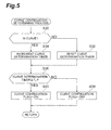
- Fig. 5 is a flowchart showing a curve continuation determining process in the steering assistance apparatus 1 in accordance with this embodiment.
- the curve continuation determining process is a process which determines whether or not the curve is continuous in the running path on which the vehicle runs, and sets (turns ON) or resets (turns OFF) a curve continuation flag.
- a series of control processes in Fig. 5 are repeatedly executed by the ECU 20 with a predetermined period, for example.
- the vehicle is in a curve or not. This determination is conducted according to the curvature value of the running path detected from the captured image. For example, it is determined that the vehicle is in the curve and not when the curvature value of the running path exceeds a predetermined curve threshold and not, respectively. In this case, whether the vehicle is in the curve or not may be determined according to not only the curvature value of the running path detected from the captured image, but also other kinds of information such as those about the steering torque or steering angle of the steering wheel, for example.
- a curve running flag is turned ON and OFF when the vehicle is in the curve and not, respectively, and whether the vehicle is in the curve or not is determined according to the ON/OFF state of the curve running flag.
- a curve determination timer is reset (S32).
- the curve determination timer is incremented (S34).
- the curve continuation flag is turned OFF (S38).
- the curve continuation flag is turned ON (S40).
- Such a curve continuation determining process can determine whether the curve of the running path is continuous or not.
- Fig. 6 is a flowchart showing a curve direction determining process in the steering assistance apparatus 1 in accordance with this embodiment.
- the curve direction determining process is a process which determines the curve direction of the running path on which the vehicle runs.
- a series of control processes in Fig. 6 are repeatedly executed by the ECU 20 with a predetermined period, for example.
- This curvature calculating process is a process which calculates the curvature of the running path according to the image captured by the camera 11. For example, a white line in the running path is extracted from the captured image, the curvature of the white line is calculated, and the curvature of the running path is calculated according to the curvature of the white line.
- the curvature of the running path is calculated such that rightward and leftward curvatures are expressed with positive and negative signs, respectively.
- the curve turning flag is a flag which indicates whether the vehicle is turning or not.
- the ON and OFF of the curve turning flags indicate that the vehicle is turning and not, respectively.
- a right curve turning timer is incremented (S64).
- the right curve turning timer is reset (S66).
- the time T1 is a set time which has been preset in the ECU 20.
- "right” is set to the curve direction flag (S82).
- the curve direction flag is a flag which indicates the curve direction of the running path. When "right” is set to the curve direction flag, it is recognized that the curve direction of the running path is rightward.
- Such a curve direction determining process makes it possible to determine whether the running path on which the vehicle runs is a right curve, a left curve, or a straight line.
- Such a curve direction determining process is an example of techniques for detecting the curve direction of the running path, so that the steering assistance apparatus 1 in accordance with this embodiment may determine the curve direction by using other techniques.
- Fig. 7 is a flowchart showing a right-turn steering determining process in the steering assistance apparatus 1 in accordance with this embodiment.
- the right-turn steering determining process is a process which determines whether the driver of the vehicle is conducting right-turn steering or not.
- a series of control processes in Fig. 7 are repeatedly executed by the ECU 20 with a predetermined period, for example.
- the right-turn steering flag is a flag which indicates whether a steering wheel turning operation is a right turn or not, such that its ON and OFF represent the right turn and not, respectively.
- a steering torque is smaller than a torque value ⁇ r OFF or not (S92).
- the torque value ⁇ r OFF is a set value which has been preset in the ECU 20 as a positive value.
- a torque value detected by the torque sensor 8 is used as the steering torque. This steering torque is detected, for example, such that right- and left-turn steering torques are expressed with positive and negative signs, respectively.
- the torque value ⁇ r ON is a set value which has been preset in the ECU 20 as a positive value greater than the torque value ⁇ r OFF .
- Such a right-turn steering determining process makes it possible to determine whether or not the driver of the vehicle is conducting right-turn steering according to the steering torque of the steering wheel.
- Fig. 8 is a flowchart showing a left-turn steering determining process in the steering assistance apparatus 1 in accordance with this embodiment.
- the left-turn steering determining process is a process which determines whether the driver of the vehicle is conducting left-turn steering or not.
- a series of control processes in Fig. 8 are repeatedly executed by the ECU 20 with a predetermined period, for example.
- the left-turn steering flag is a flag which indicates whether a steering wheel turning operation is a left turn or not, such that its ON and OFF represent the left turn and not, respectively.
- a steering torque is greater than a torque value ⁇ r OFF or not (S102).
- the torque value ⁇ l OFF is a set value which has been preset in the ECU 20 as a negative value.
- a torque value detected by the torque sensor 8 is used as the steering torque.
- the torque value ⁇ l ON is a set value which has been preset in the ECU 20 as a negative value smaller than the torque value ⁇ l OFF .
- Such a left-turn steering determining process makes it possible to determine whether or not the driver of the vehicle is conducting left-turn steering according to the steering torque of the steering wheel.
- Fig. 9 is a flowchart showing a curve exit determining process in the steering assistance apparatus 1 in accordance with this embodiment.
- the curve exit determining process is a process which determines whether the running path (road) on which the vehicle runs is a curve exit or not.
- a series of control processes in Fig. 9 are repeatedly executed by the ECU 20 with a predetermined period, for example.
- the curve turning flag is ON or not.
- the maximum curvature value C max is a value which indicates the maximum curvature of the running path during when the vehicle runs through a curve, and is updated as needed during the curve running.
- a curve exit determination release timer is reset (S114)
- a curve exit determination completion timer is reset (S116)
- OFF is set to a curve exit flag (S118). Then, the flow shifts to S150.
- the curve exit determination release timer is reset (S126).
- the curve determination coefficient Kr is a coefficient which has been preset to a value of 0.30 to 0.40, for example, in the ECU 20 according to a state where the road can be considered straight.
- the curve exit determination completion timer is reset (S132). Then, the flow shifts to S134.
- the curve exit determination completion timer is incremented (S130). Then, the flow shifts to S134.
- the third time T3 is a set time which has been preset in the ECU 20.
- ON is set to the curve exit flag (S136).
- the curve exit flag is a flag which indicates that the running path on which the vehicle runs is a curve exit.
- the ON and OFF of the curve exit flag indicate that the running path is at the curve exit and not, respectively.
- the curve exit determination completion timer is reset (S138). Then, it is determined whether or not the absolute value of road curvature is greater than the value obtained by multiplying the maximum curvature value C max by the curve exit determination coefficient Kr (S140). When the absolute value of road curvature is not greater than the value obtained by multiplying the maximum curvature value C max by the curve exit determination coefficient Kr, the curve exit determination completion timer is reset (S142). Then, the flow shifts to S146. When the absolute value of road curvature is greater than the value obtained by multiplying the maximum curvature value C max by the curve exit determination coefficient Kr, on the other hand, the curve exit determination completion timer is incremented (S144). Then, the flow shifts to S146.
- the fourth time T4 is a set time which has been preset in the ECU 20.
- the flow shifts to S 136, where ON is set to the curve exit flag.
- the curve exit determination release timer exceeds the fourth time T4
- the flow shifts to S 148, where OFF is set to the curve exit flag. Then, the flow shifts to S150.
- the data of the curve exit flag is set to the previous value of curve exit flag. Then, the series of processes in the curve exit determining process are terminated.
- such a curve exit determining process turns the curve exit flag ON when the road curvature of the running path on which the vehicle runs decreases from the maximum curvature value C max to the set value (Kr ⁇ C max ), and thus can detect that the running path of the vehicle is the curve exit.
- Such a curve exit determining process is an example of techniques for detecting a curve exit of the running path, so that the steering assistance apparatus 1 in accordance with this embodiment may determine the curve exit by using other techniques.
- the steering assistance apparatus 1 determines that the vehicle is running through a curve exit according to the fact that the curve direction estimated from the image processing and the steering direction estimated from the steering operation of the driver do not coincide with each other. Since whether the vehicle is at the curve exit or not is determined not only from the image processing but also according to the steering operation of the driver, the curve exit of the running path can be detected accurately. This enables appropriate steering assistance control by which the vehicle runs along the running path.
- the steering assistance apparatus 1 in accordance with this embodiment can enhance the amount of change in steering torque by turning the curvature change ratio limitation alleviation flag ON, so as to increase the amount of steering for turning back the steering wheel at the curve exit. This can suppress the delay in turning back the steering wheel at the curve exit. Therefore, the vehicle runs so as to follow the running path, which enables steering assistance control with an excellent running path following capability.
- the present invention alleviates the limitation on the curvature change ratio at the curve exit, and thus can increase the amount of steering for turning back the steering wheel at the curve exit, thereby allowing the vehicle to run along the running path B.
- the steering assistance apparatus 1 in accordance with this embodiment turns the curvature change ratio limitation alleviation flag OFF, so as not to make the amount of change in steering torque during turning back the steering wheel greater than that when the vehicle is not at the curve exit. This can prevent inappropriate steering assistance control from being performed under the influence of noise.
- the above-mentioned embodiment illustrates only an example of the steering assistance apparatus in accordance with the present invention.
- the steering assistance apparatus in accordance with the present invention is not limited to the above, but may be anything in which the steering assistance apparatus in accordance with the embodiment is modified or applied to others so as not to alter the gist recited in each claim.
- the present invention can accurately detect the curve exit and perform steering assistance control with an excellent running path following capability.
Landscapes
- Engineering & Computer Science (AREA)
- Chemical & Material Sciences (AREA)
- Combustion & Propulsion (AREA)
- Transportation (AREA)
- Mechanical Engineering (AREA)
- Steering Control In Accordance With Driving Conditions (AREA)
- Power Steering Mechanism (AREA)
Abstract
Description
- The present invention relates to a steering assistance apparatus which assists steering by providing a steering mechanism of a vehicle with a steering torque.
- Conventionally known as a steering assistance apparatus which assists steering by providing a steering mechanism of a vehicle with a steering torque is one capturing an image in front of the vehicle with a camera, detecting a running path and the position of the vehicle with respect to the running path according to the captured image information, calculating a basic steering assist torque according to the form of the running path, calculating a corrected steering assist torque according to the position of the vehicle, calculating an output steering assist torque according to the basic steering assist torque and corrected steering assist torque, and determining an amount of operation of a steering actuator according to the output steering assist torque as described in Japanese Patent Application Laid-Open No.
2001-10518 - When a vehicle running through a curve reaches an exit of the curve, a delay may occur in turning back the steering wheel in such a steering assistance apparatus. In this case, because of the delay in turning back the steering wheel, the running of the vehicle fails to follow the running path, whereby the driver of the vehicle feels a sense of discomfort.
- It is therefore an object of the present invention to provide a steering assistance apparatus which can perform steering assistance control with an excellent running path following capability by accurately detecting a curve exit.
- Namely, the steering assistance apparatus in accordance with the present invention is a steering assistance apparatus for providing a steering mechanism with a steering torque such that a vehicle runs along a running path according to an image capturing the running path in front of the vehicle, the apparatus comprising curve direction estimating means for estimating a curve direction of the running path by processing the image, steering direction estimating means for estimating a steering direction of a driver of the vehicle according to a steering operation of the driver, and curve exit determining means for determining that the vehicle is running through a curve exit according to a fact that the curve direction estimated by the curve direction estimating means and the steering direction estimated by the steering direction estimating means do not coincide with each other.
- In the present invention, it is determined that the vehicle is running through a curve exit according to the fact that the curve direction estimated from the image processing and the steering direction estimated from the steering operation of the driver do not coincide with each other. This can accurately determine the curve exit of the running path, whereby appropriate steering assistance control can be performed.
- Preferably, the steering assistance apparatus in accordance with the present invention further comprises steering control means for making a greater amount of change in the steering torque during turning back a steering wheel when the curve exit determining means determines that the vehicle is running through the curve exit than when not.
- This can enhance the amount of steering for turning back the steering wheel at the curve exit by increasing the amount of change in the steering torque when it is determined that the vehicle is at the curve exit. As a consequence, the delay in turning back the steering wheel at the curve exit can be suppressed. Therefore, the vehicle runs so as to follow the running path, which enables steering assistance control with an excellent running path following capability.
- Preferably, when a curvature value of the running path calculated through the image processing incurs a predetermined level of noise or greater in the steering assistance apparatus in accordance with the present invention, even if the curve exit determining means determines that the vehicle is running through the curve exit, the steering control means keeps the amount of change in steering torque during turning back the steering wheel from becoming greater than that when not.
- Here, when the curvature value of the running path calculated through the image processing incurs a predetermined level of noise or greater, even if it is determined by the curve exit determining means that the vehicle is running through the curve exit, the steering control means does not make the amount of change in steering torque during turning back the steering wheel greater than that when not, whereby inappropriate steering assistance control can be prevented from being performed under the influence of noise.
- By detecting a curve exit according to the fact that the curve direction of the running path and the steering direction of the driver do not coincide with each other, the present invention can accurately detect the curve exit and perform steering assistance control with an excellent running path following capability.
-
- [
Fig. 1 ] is a structural schematic diagram of a steering assistance apparatus in accordance with an embodiment of the present invention; - [
Fig. 2 ] is a block diagram of steering assistance control in the steering assistance apparatus ofFig. 1 ; - [
Fig. 3 ] is a flowchart showing a curvature change ratio limitation alleviating process in the steering assistance apparatus ofFig. 1 ; - [
Fig. 4 ] is a flowchart showing a curve exit error determining process in the steering assistance apparatus ofFig. 1 ; - [
Fig. 5 ] is a flowchart showing a curve continuation determining process in the steering assistance apparatus ofFig. 1 ; - [
Fig. 6 ] is a flowchart showing a curve direction determining process in the steering assistance apparatus ofFig. 1 ; - [
Fig. 7 ] is a flowchart showing a right-turn steering determining process in the steering assistance apparatus ofFig. 1 ; - [
Fig. 8 ] is a flowchart showing a left-turn steering determining process in the steering assistance apparatus ofFig. 1 ; - [
Fig. 9 ] is a flowchart showing a curve exit determining process in the steering assistance apparatus ofFig. 1 ; - [
Fig. 10 ] is a graph showing a state of change in road curvature in the curve exit determining process ofFig. 9 ; and - [
Fig. 11 ] is a view for explaining the running path following capability of steering assistance control in the steering assistance control apparatus ofFig. 1 . - In the following, embodiments of the present invention will be explained in detail with reference to the accompanying drawings. In the explanation of the drawings, the same constituents will be referred to with the same numerals or letters while omitting their overlapping descriptions.
-
Fig. 1 is a structural schematic diagram of the steering assistance apparatus in accordance with an embodiment of the present invention.
As shown inFig. 1 , thesteering assistance apparatus 1 in accordance with this embodiment is an apparatus which assists a driver of a vehicle in steering by providing a steering force transmitting system of the vehicle with a steering torque, and used for one which performs lane-keep control for keeping the vehicle at the center position of a lane which is a running path to run, for example. The steering force transmitting system of the vehicle is mainly constituted by asteering shaft 3, agear unit 4, andtie rods 6. Thesteering shaft 3 is connected to a steering wheel 2, and transmits the steering force of the steering wheel 2 to thegear unit 4 andtie rods 6. - The
gear unit 4 is one which converts the steering torque transmitted from thesteering shaft 3 into a horizontal force. As thegear unit 4, that of rack and pinion type is used, for example. Thegear unit 4 receives an assist force from anassist motor 5 and moves thetie rods 6, so as to turnsteerable wheels 7. - The
gear unit 4 is provided with atorque sensor 8. Thetorque sensor 8 functions as steering torque detecting means which detects the steering torque of the steering wheel 2. Employed as thetorque sensor 8, for example, is one in which a torsion bar (not depicted) is arranged between thesteering shaft 3 and a pinion shaft (not depicted), while a torsion of the torsion bar is detected by two rotation sensors (not depicted) in response to the steering torque. - The
motor 5 is one which assists the steering force of the steering wheel 2, and supplies an assist force corresponding to the steering torque or the like to the steering force transmitting system, for example. ThoughFig. 1 shows themotor 5 as that of a rack assist type which provides a rack with an assist force, other types such as column assist types may also be employed. - The
steering assistance apparatus 1 is provided with an ECU (Electronic Control Unit) 20. TheECU 20 performs a control process for the whole apparatus, and is constituted by a CPU, a ROM, a RAM, an input signal circuit, an output signal circuit, a power circuit, and the like, for example. Thesteering assistance apparatus 1 is provided with acamera 11. Thecamera 11, for which a CCD camera or the like, for example, is used, functions as imaging means for capturing an image in front of the vehicle. Image information captured by thecamera 11 is fed into theECU 20. - The
ECU 20 functions as vehicle position detecting means for detecting the position of the vehicle with respect to the width direction of a running path (road). For example, theECU 20 processes a captured image, recognizes a white line included in the image information, and detects the position of the vehicle with respect to the width direction of the running path according to the form and position of the recognized white line. Here, the positional deviation of the vehicle from the center position of the lane is referred to as offset. - The
ECU 20 also functions as vehicle orientation detecting means which detects the orientation of the vehicle with respect to the white line of the running path according to the image information. For example, theECU 20 processes the captured image, recognizes the white line included in the image information, and detects the orientation of the vehicle with respect to the while line according to the direction in which the recognized white line extends and the like. - The
ECU 20 also functions as curve direction estimating means which estimates the curve direction of the running path according to the image information. For example, the ECU 20 estimates the curve direction of the running path according to the direction in which the white line extends and the like. The curve of the running path refers to those bent at a predetermined curvature or greater and encompasses corners of the running path. - The
ECU 20 also functions as steering direction estimating means which estimates the steering direction of the driver of the vehicle according to a steering operation of the driver. For example, theECU 20 detects a steering torque as the steering operation of the driver, and estimates the steering direction of the driver according to the state of steering torque. - The
ECU 20 also functions as curve exit determining means which determines that the vehicle is running through a curve exit according to a fact that the curve direction estimated by the curve direction estimating means and the steering direction estimated by the steering direction estimating means do not coincide with each other. Further, theECU 20 functions as steering control means which increases an amount of change in the steering torque during turning back a steering wheel when the curve exit determining means determines that the vehicle is running through the curve exit than when not. - The
steering assistance apparatus 1 is provided with avehicle speed sensor 12. Thevehicle speed sensor 12 functions as vehicle speed detecting means which detects the running speed of the vehicle. For example, a wheel speed sensor is used as thevehicle speed sensor 12. -
Fig. 2 is a schematic diagram of a basic control block for steering assistance control in thesteering assistance apparatus 1 in accordance with this embodiment. - In the
steering assistance apparatus 1, as shown inFig. 2 , the image information of the running path in front of the vehicle captured by thecamera 11 is fed into theECU 20, and the curvature of the running path (R), the vehicle position (D), and the orientation of the vehicle with respect to the white line (θ) are detected according to the image information. The curvature of the running path is calculated, for example, by extracting a white line in the running path and detecting the curvature of the white line. Thus calculated curvature value is processed through a filter, since it includes noise. The filter processing restrains the ratio of change in the curvature value from increasing. - The vehicle position is the position of the vehicle with respect to the width direction of the running path. The vehicle position is calculated according to the state of detection of the white line, for example. The orientation of the vehicle with respect to the white line is calculated according to the state of detection of left and right white lines, for example.
- The curvature of the running path, the vehicle position, and the vehicle orientation are multiplied by a predetermined gain (G) and then used for calculating a target lateral acceleration. The target lateral acceleration is a lateral acceleration required for returning the vehicle to the center of the lane. By multiplying the target lateral acceleration by a predetermined coefficient, a steering torque (assist steering force) required for keeping the lane is calculated. This steering torque is fed to the steering mechanism.
- On the other hand, in response to the steering wheel turning force of the driver of the vehicle, the actuator (motor 5) of electric power steering (EPS) provides an assist force. Then, the actuator of the electric power steering supplies the steering wheel turning force and assist force to the steering mechanism.
- The steering wheel turning force, the assist force for turning the steering wheel, and the assist steering force for keeping the lane are fed as a steering force to the steering mechanism. In response to the steering force, the vehicle changes its advancing direction.
-
Fig. 3 is a flowchart showing a curvature change ratio limitation alleviating process in thesteering assistance apparatus 1 in accordance with this embodiment. - The curvature change ratio limitation alleviating process is a process for setting (turning ON) or resetting (turning OFF) a curvature change ratio limitation alleviation flag. A series of control processes in
Fig. 3 are repeatedly executed by theECU 20 with a predetermined period, for example. - First, as shown in S10 of
Fig. 3 , it is determined whether or not the steering operation of the driver of the vehicle differs from that toward the curve direction, the curve of the running path is continuous, and the noise in the curvature value of the running path detected from the captured image is lower than a predetermined level. - Whether or not the steering operation of the driver of the vehicle differs from that toward the curve direction is determined by comparing the curve direction of the running path with the steering direction of the driver. When the steering direction of the driver does not coincide with the curve direction of the running path, it is determined that the steering operation of the driver of the vehicle differs from that toward the curve direction. When the steering direction of the driver coincides with the curve direction of the running path, it is determined that the steering operation of the driver of the vehicle is that toward the curve direction.
- Specifically, it is determined that the steering operation of the driver of the vehicle differs from that toward the curve direction when the previous value of a curve direction flag is right and a right-turn steering flag is OFF or when the previous value of curve direction flag is left and a left-turn steering flag is OFF. On the other hand, it is determined that the steering operation of the driver of the vehicle is that toward the curve direction when the previous value of curve direction flag is right and the right-turn steering flag is ON or when the previous value of curve direction flag is left and the left-turn steering flag is ON.
- Whether the curve of the running path is continuous or not is determined, for example, by subjecting the captured image of the
camera 11 to image processing and arithmetic operations, so as to calculate the curvature of the running path. When the curvature is a set curvature or greater, it is determined that the curve is continuous. When the curvature of the running path is smaller than the set curvature, it is determined that the curve is discontinuous. Specifically, it is determined that the curve of the running path is continuous and not when a curve continuation flag is ON and OFF, respectively. - Whether the noise in the curvature value of the running path detected from the captured image is lower than a predetermined level or not is determined according to whether or not the curvature value at the curve exit of the running path calculated according to the image captured by the
camera 11 fluctuates by a set value or more. For example, it is determined according to whether a curve exit error determination flag is OFF or not. - When it is determined at S10 that the steering operation of the driver of the vehicle is that toward the curve direction, the curve of the running path is discontinuous, or the noise in the curvature value of the running path detected from the captured image is at a predetermined level or greater, the curvature change ratio limitation alleviation flag is turned OFF (S12). Namely, when the steering operation of the driver of the vehicle is that toward the curve direction, it is determined that the vehicle is not at the curve exit.
- When the curvature change ratio limitation alleviation flag is turned OFF, the limitation to the change ratio is not alleviated in the curvature value of the running path that is repeatedly calculated with a predetermined period. Namely, the noise reducing function of the filter that reduces the noise in the curvature value is kept, whereby the curvature value is restrained from fluctuating greatly.
- When it is determined at S10 that the steering operation of the driver of the vehicle differs from that toward the curve direction, the curve of the running path is continuous, or the noise included in the curvature value of the running path detected from the captured image is lower than the predetermined level, the curvature change ratio limitation alleviation flag is turned ON (S14).
- Namely, when the steering operation of the driver of the vehicle differs from that toward the curve direction and the curve of the running path is continuous, the curve is continuous, while no steering is operated toward the curve direction, whereby it is determined that the running path is the curve exit.
- When the curvature change ratio limitation alleviation flag is turned ON, the limitation to the change ratio is alleviated in the curvature value of the running path that is repeatedly calculated with a predetermined period. Namely, the noise reducing function of the filter that reduces the noise in the curvature value is alleviated, whereby the curvature value is allowed to fluctuate greatly. This makes it possible to calculate the curvature value along the curve of the running path.
- After setting or resetting the flag at S12 or
S 14, the process for controlling the curvature change ratio limitation alleviating process is terminated. - In this curvature change ratio limitation alleviating process, the curvature change ratio limitation alleviation flag is turned ON according to the fact that the steering operation of the driver of the vehicle differs from that toward the curve direction, so as to alleviate the change ratio of the curvature value of the running path. Therefore, the curvature value along the running path can be calculated at the curve exit.
- When the noise in the curvature value of the running path detected from the captured image is at a predetermined level or greater, the curvature change ratio limitation alleviation flag is turned OFF, so as to keep the noise reducing function of the noise reducing filter for the curvature value, whereby inappropriate curvature values can be restrained from being calculated.
-
Fig. 4 is a flowchart showing a curve exit error determining process in thesteering assistance apparatus 1 in accordance with this embodiment. - The curve exit error determining process is a process for setting (turning ON) or resetting (turning OFF) a curve exit error flag. The curve exit error flag is a flag which indicates that the determination of the curve exit, i.e., clothoid exit, is wrong. The determination becomes erroneous because of the noise occurring in the running path. A series of control processes in
Fig. 4 are repeatedly executed by theECU 20 with a predetermined period, for example. - First, as shown in S20 of
Fig. 4 , it is determined whether the curve exit error flag is OFF or not. When the curve exit error flag is not OFF at S20, it is determined whether the previous value of curve exit error flag is OFF or not (S22). When the previous value of curve exit error flag is not OFF at S22, the curve exit error determining process is terminated. When the previous value of curve exit error flag is OFF at S22, on the other hand, the curve exit error flag is turned OFF (S24). - When the curve exit error flag is OFF at S20, it is determined whether or not the previous value of curve exit error flag is ON and the curvature value of the running path incurs a predetermined level of fluctuation or more (S26). Whether or not the curvature value of the running path incurs a predetermined level of fluctuation or more is determined, for example, according to whether or not the curvature value fluctuates across a threshold indicating the curve exit. Namely, when the curvature value exceeds a set threshold soon after falling down therefrom, it is determined that the curvature value incurs a predetermined level of fluctuation or more.
- When it is determined at S26 that the previous value of curve exit error flag is not ON or that the fluctuation of the curvature value of the running path is smaller than the predetermined level, the curve exit error determining process is terminated. When it is determined at S26 that the previous value of curve exit error flag is ON and that the curvature value of the running path incurs a predetermined level of fluctuation or more, the curve exit error flag is turned ON (S28). After the process at S28 ends, the curve exit error determining process is terminated.
- In such a curve exit error determining process, the curve exit error flag is turned ON according to the fact that the curvature value of the running path incurs a predetermined level of fluctuation or more, whereby it can be recognized that the determination of the curve exit is erroneous.
-
Fig. 5 is a flowchart showing a curve continuation determining process in thesteering assistance apparatus 1 in accordance with this embodiment. - The curve continuation determining process is a process which determines whether or not the curve is continuous in the running path on which the vehicle runs, and sets (turns ON) or resets (turns OFF) a curve continuation flag. A series of control processes in
Fig. 5 are repeatedly executed by theECU 20 with a predetermined period, for example. - First, as shown in S30 of
Fig. 5 , it is determined whether the vehicle is in a curve or not. This determination is conducted according to the curvature value of the running path detected from the captured image. For example, it is determined that the vehicle is in the curve and not when the curvature value of the running path exceeds a predetermined curve threshold and not, respectively. In this case, whether the vehicle is in the curve or not may be determined according to not only the curvature value of the running path detected from the captured image, but also other kinds of information such as those about the steering torque or steering angle of the steering wheel, for example. - Preferably, a curve running flag is turned ON and OFF when the vehicle is in the curve and not, respectively, and whether the vehicle is in the curve or not is determined according to the ON/OFF state of the curve running flag.
- When it is determined at S30 that the vehicle is not in the curve, a curve determination timer is reset (S32). When it is determined at S30 that the vehicle is in the curve, the curve determination timer is incremented (S34).
- Then, the flow shifts to S36, where it is determined whether or not the curve determination timer T is a set time To or more. When the curve determination timer T is less than the set time T0 at S36, the curve continuation flag is turned OFF (S38). When the curve determination timer T is the set time T0 or more at S36, on the other hand, the curve continuation flag is turned ON (S40). After the process at S40 ends, the curve continuation determining process is terminated.
- Such a curve continuation determining process can determine whether the curve of the running path is continuous or not.
-
Fig. 6 is a flowchart showing a curve direction determining process in thesteering assistance apparatus 1 in accordance with this embodiment. - The curve direction determining process is a process which determines the curve direction of the running path on which the vehicle runs. A series of control processes in
Fig. 6 are repeatedly executed by theECU 20 with a predetermined period, for example. - First, as shown in S60 of
Fig. 6 , a road curvature calculating process is performed. This curvature calculating process is a process which calculates the curvature of the running path according to the image captured by thecamera 11. For example, a white line in the running path is extracted from the captured image, the curvature of the white line is calculated, and the curvature of the running path is calculated according to the curvature of the white line. The curvature of the running path is calculated such that rightward and leftward curvatures are expressed with positive and negative signs, respectively. - Then, the flow shifts to S62, where it is determined whether or not a curve turning flag is ON and the road curvature is greater than zero. The curve turning flag is a flag which indicates whether the vehicle is turning or not. The ON and OFF of the curve turning flags indicate that the vehicle is turning and not, respectively.
- When the curve turning flag is ON and the road curvature is greater than zero at S62, a right curve turning timer is incremented (S64). When the curve turning flag is not ON and the road curvature is not greater than zero at S62, the right curve turning timer is reset (S66).
- Then, the flow shifts to S68, where it is determined whether or not the curve turning flag is ON and the road curvature is less than zero. When the curve turning flag is ON and the road curvature is less than zero at S68, a left curve turning timer is incremented (S70). When the curve turning flag is not ON and the road curvature is not less than zero, on the other hand, the left curve turning timer is reset (S72).
- Then, the flow shifts to S74, where it is determined whether the right curve turning timer exceeds a time T1 or not. The time T1 is a set time which has been preset in the
ECU 20. When the right curve turning timer exceeds the time T1, "right" is set to the curve direction flag (S82). The curve direction flag is a flag which indicates the curve direction of the running path. When "right" is set to the curve direction flag, it is recognized that the curve direction of the running path is rightward. - When the right curve turning timer does not exceed the time T1 at S74, on the other hand, it is determined whether the left curve turning timer exceeds the time T1 or not (S76). When the left curve turning timer exceeds the time T1, "left" is set to the curve direction flag (S78). When the left curve turning timer does not exceed the time T1 at S74, "NO" is set to the curve direction flag (S80). When "left" is set to the curve direction flag, it is recognized that the curve direction of the running path is leftward. When "NO" is set to the curve direction flag, it is recognized that the running path is neither a right curve nor a left curve, but a straight line.
- Such a curve direction determining process makes it possible to determine whether the running path on which the vehicle runs is a right curve, a left curve, or a straight line. Such a curve direction determining process is an example of techniques for detecting the curve direction of the running path, so that the
steering assistance apparatus 1 in accordance with this embodiment may determine the curve direction by using other techniques. -
Fig. 7 is a flowchart showing a right-turn steering determining process in thesteering assistance apparatus 1 in accordance with this embodiment. - The right-turn steering determining process is a process which determines whether the driver of the vehicle is conducting right-turn steering or not. A series of control processes in
Fig. 7 are repeatedly executed by theECU 20 with a predetermined period, for example. - First, as shown in S90 of
Fig. 7 , it is determined whether the right-turn steering flag is OFF or not. The right-turn steering flag is a flag which indicates whether a steering wheel turning operation is a right turn or not, such that its ON and OFF represent the right turn and not, respectively. - When it is determined at S90 that the right-turn steering flag is not OFF, it is determined whether a steering torque is smaller than a torque value τrOFF or not (S92). The torque value τrOFF is a set value which has been preset in the
ECU 20 as a positive value. As the steering torque, a torque value detected by thetorque sensor 8 is used. This steering torque is detected, for example, such that right- and left-turn steering torques are expressed with positive and negative signs, respectively. - When the steering torque is not smaller than the torque value τrOFF at S92, it is determined that a steering wheel right-turning operation is continuously conducted, whereby the right-turn steering determining process is terminate. When the steering torque is smaller than the torque value τrOFF at S92, on the other hand, the right-turn steering flag is turned OFF (S94).
- When it is determined at S90 that the right-turn steering flag is OFF, it is determined whether the steering torque is greater than a torque value τrON or not (S96). The torque value τrON is a set value which has been preset in the
ECU 20 as a positive value greater than the torque value τrOFF. - When the steering torque is not greater than the torque value τrON at S96, it is determined that no steering wheel right-turning operation is conducted, whereby the right-turn steering determining process is terminated. When the steering torque is greater than the torque value τrON at S96, on the other hand, it is determined that the right-turn steering is conducted, whereby the right-turn steering flag is turned ON (S98). Then, the right-turn steering determining process is terminated.
- Such a right-turn steering determining process makes it possible to determine whether or not the driver of the vehicle is conducting right-turn steering according to the steering torque of the steering wheel.
-
Fig. 8 is a flowchart showing a left-turn steering determining process in thesteering assistance apparatus 1 in accordance with this embodiment. - The left-turn steering determining process is a process which determines whether the driver of the vehicle is conducting left-turn steering or not. A series of control processes in
Fig. 8 are repeatedly executed by theECU 20 with a predetermined period, for example. - First, as shown in S100 of
Fig. 8 , it is determined whether the left-turn steering flag is OFF or not. The left-turn steering flag is a flag which indicates whether a steering wheel turning operation is a left turn or not, such that its ON and OFF represent the left turn and not, respectively. - When it is determined at S100 that the left-turn steering flag is not OFF, it is determined whether a steering torque is greater than a torque value τrOFF or not (S102). The torque value τlOFF is a set value which has been preset in the
ECU 20 as a negative value. As the steering torque, a torque value detected by thetorque sensor 8 is used. - When the steering torque is not greater than the torque value τrOFF at S102, it is determined that a steering wheel left-turning operation is continuously conducted, whereby the left-turn steering determining process is terminated. When the steering torque is greater than the torque value τlOFF at S102, on the other hand, the left-turn steering flag is turned OFF (S104).
- When it is determined at
S 100 that the left-turn steering flag is OFF, it is determined whether the steering torque is smaller than a torque value τlON or not (S106). The torque value τlON is a set value which has been preset in theECU 20 as a negative value smaller than the torque value τlOFF. - When the steering torque is not smaller than the torque value τlON at S106, it is determined that no steering wheel left-turning operation is conducted, whereby the left-turn steering determining process is terminated. When the steering torque is smaller than the torque value τlON at
S 106, on the other hand, it is determined that the left-turn steering is conducted, whereby the left-turn steering flag is turned ON (S108). Then, the left-turn steering determining process is terminated. - Such a left-turn steering determining process makes it possible to determine whether or not the driver of the vehicle is conducting left-turn steering according to the steering torque of the steering wheel.
-
Fig. 9 is a flowchart showing a curve exit determining process in thesteering assistance apparatus 1 in accordance with this embodiment. - The curve exit determining process is a process which determines whether the running path (road) on which the vehicle runs is a curve exit or not. A series of control processes in
Fig. 9 are repeatedly executed by theECU 20 with a predetermined period, for example. - First, as shown in S110 of
Fig. 9 , it is determined whether the curve turning flag is ON or not. When the curve turning flag is not ON, zero is set to the maximum curvature value Cmax during curve running (S112). The maximum curvature value Cmax is a value which indicates the maximum curvature of the running path during when the vehicle runs through a curve, and is updated as needed during the curve running. Subsequently, a curve exit determination release timer is reset (S114), a curve exit determination completion timer is reset (S116), and OFF is set to a curve exit flag (S118). Then, the flow shifts to S150. - When the curve turning flag is ON at S110, on the other hand, it is determined whether or not the absolute value of road curvature is greater than the maximum curvature value Cmax during the curve running (S120). When the absolute value of road curvature is not greater than the maximum curvature value Cmax during the curve running, the flow shifts to S124. When the absolute value of road curvature is greater than the maximum curvature value Cmax during the curve running, on the other hand, the absolute value of road curvature is set as the maximum curvature value Cmax (S122).
- Then, the flow shifts to S124, where it is determined whether the previous value of curve exit flag is OFF or not. When the previous value of curve exit flag is OFF, the curve exit determination release timer is reset (S126). Then, it is determined whether or not the absolute value of road curvature is smaller than a value obtained by multiplying the maximum curvature value Cmax by a curve exit determination coefficient Kr (S128). The curve determination coefficient Kr is a coefficient which has been preset to a value of 0.30 to 0.40, for example, in the
ECU 20 according to a state where the road can be considered straight. - When the absolute value of road curvature is not smaller than the value obtained by multiplying the maximum curvature value Cmax by the curve exit determination coefficient Kr, the curve exit determination completion timer is reset (S132). Then, the flow shifts to S134. When the absolute value of road curvature is smaller than the value obtained by multiplying the maximum curvature value Cmax by the curve exit determination coefficient Kr at S128, on the other hand, the curve exit determination completion timer is incremented (S130). Then, the flow shifts to S134.
- At S134, it is determined whether the curve exit determination completion timer exceeds a third time T3 or not. The third time T3 is a set time which has been preset in the
ECU 20. When the curve exit determination completion timer exceeds the third time T3, ON is set to the curve exit flag (S136). The curve exit flag is a flag which indicates that the running path on which the vehicle runs is a curve exit. The ON and OFF of the curve exit flag indicate that the running path is at the curve exit and not, respectively. When the curve exit determination completion timer does not exceed the third time T3 atS 134, the flow shifts to S148, where OFF is set to the curve exit flag (S148). - When the previous value of curve exit flag is not OFF at S124, the curve exit determination completion timer is reset (S138). Then, it is determined whether or not the absolute value of road curvature is greater than the value obtained by multiplying the maximum curvature value Cmax by the curve exit determination coefficient Kr (S140). When the absolute value of road curvature is not greater than the value obtained by multiplying the maximum curvature value Cmax by the curve exit determination coefficient Kr, the curve exit determination completion timer is reset (S142). Then, the flow shifts to S146. When the absolute value of road curvature is greater than the value obtained by multiplying the maximum curvature value Cmax by the curve exit determination coefficient Kr, on the other hand, the curve exit determination completion timer is incremented (S144). Then, the flow shifts to S146.
- At S146, it is determined whether the curve exit determination release timer exceeds a fourth time T4 or not. The fourth time T4 is a set time which has been preset in the
ECU 20. When the curve exit determination release timer does not exceed the fourth time T4, the flow shifts toS 136, where ON is set to the curve exit flag. When the curve exit determination release timer exceeds the fourth time T4, on the other hand, the flow shifts to S 148, where OFF is set to the curve exit flag. Then, the flow shifts to S150. - At S150, the data of the curve exit flag is set to the previous value of curve exit flag. Then, the series of processes in the curve exit determining process are terminated.
- As shown in
Fig. 10 , such a curve exit determining process turns the curve exit flag ON when the road curvature of the running path on which the vehicle runs decreases from the maximum curvature value Cmax to the set value (Kr·Cmax), and thus can detect that the running path of the vehicle is the curve exit. Such a curve exit determining process is an example of techniques for detecting a curve exit of the running path, so that thesteering assistance apparatus 1 in accordance with this embodiment may determine the curve exit by using other techniques. - As in the foregoing, the
steering assistance apparatus 1 in accordance with this embodiment determines that the vehicle is running through a curve exit according to the fact that the curve direction estimated from the image processing and the steering direction estimated from the steering operation of the driver do not coincide with each other. Since whether the vehicle is at the curve exit or not is determined not only from the image processing but also according to the steering operation of the driver, the curve exit of the running path can be detected accurately. This enables appropriate steering assistance control by which the vehicle runs along the running path. - When it is determined that the vehicle is at the curve exit ("Yes" at S 10 of
Fig. 10 ), thesteering assistance apparatus 1 in accordance with this embodiment can enhance the amount of change in steering torque by turning the curvature change ratio limitation alleviation flag ON, so as to increase the amount of steering for turning back the steering wheel at the curve exit. This can suppress the delay in turning back the steering wheel at the curve exit. Therefore, the vehicle runs so as to follow the running path, which enables steering assistance control with an excellent running path following capability. - When a vehicle A runs through a curve of a running path B under steering assistance control as shown in
Fig. 11 , for example, one not based on the steering assistance control of the present invention cannot increase the amount of steering for turning back the steering wheel at the curve exit, since the curvature change ratio is limited, whereby it becomes difficult for the vehicle to run along the running path B. On the other hand, the present invention alleviates the limitation on the curvature change ratio at the curve exit, and thus can increase the amount of steering for turning back the steering wheel at the curve exit, thereby allowing the vehicle to run along the running path B. - Further, when the curvature value of the running path calculated through the image processing incurs a predetermined level of noise or greater ("No" at S10 of
Fig. 3 ), even if it is determined that the vehicle is running through the curve exit, thesteering assistance apparatus 1 in accordance with this embodiment turns the curvature change ratio limitation alleviation flag OFF, so as not to make the amount of change in steering torque during turning back the steering wheel greater than that when the vehicle is not at the curve exit. This can prevent inappropriate steering assistance control from being performed under the influence of noise. - The above-mentioned embodiment illustrates only an example of the steering assistance apparatus in accordance with the present invention. The steering assistance apparatus in accordance with the present invention is not limited to the above, but may be anything in which the steering assistance apparatus in accordance with the embodiment is modified or applied to others so as not to alter the gist recited in each claim.
- By detecting a curve exit according to the fact that the curve direction of the running path and the steering direction of the driver do not coincide with each other, the present invention can accurately detect the curve exit and perform steering assistance control with an excellent running path following capability.
Claims (3)
- A steering assistance apparatus for providing a steering mechanism with a steering torque such that a vehicle runs along a running path according to an image capturing the running path in front of the vehicle, the apparatus comprising:curve direction estimating means for estimating a curve direction of the running path by processing the image;steering direction estimating means for estimating a steering direction of a driver of the vehicle according to a steering operation of the driver; andcurve exit determining means for determining that the vehicle is running through a curve exit according to a fact that the curve direction estimated by the curve direction estimating means and the steering direction estimated by the steering direction estimating means do not coincide with each other.
- A steering assistance apparatus according to claim 1, further comprising steering control means for making a greater amount of change in the steering torque during turning back a steering wheel when the curve exit determining means determines that the vehicle is running through the curve exit than when not.
- A steering assistance apparatus according to claim 2, wherein, when a curvature value of the running path calculated through the image processing incurs a predetermined level of noise or greater, even if the curve exit determining means determines that the vehicle is running through the curve exit, the steering control means keeps the amount of change in steering torque during turning back the steering wheel from becoming greater than that when not.
Applications Claiming Priority (2)
| Application Number | Priority Date | Filing Date | Title |
|---|---|---|---|
| JP2006214754A JP4432941B2 (en) | 2006-08-07 | 2006-08-07 | Steering support device |
| PCT/JP2007/065794 WO2008018610A1 (en) | 2006-08-07 | 2007-08-06 | Steering support device |
Publications (3)
| Publication Number | Publication Date |
|---|---|
| EP2050657A1 true EP2050657A1 (en) | 2009-04-22 |
| EP2050657A4 EP2050657A4 (en) | 2010-03-24 |
| EP2050657B1 EP2050657B1 (en) | 2017-04-12 |
Family
ID=39033132
Family Applications (1)
| Application Number | Title | Priority Date | Filing Date |
|---|---|---|---|
| EP07792437.1A Active EP2050657B1 (en) | 2006-08-07 | 2007-08-06 | Steering support device |
Country Status (5)
| Country | Link |
|---|---|
| US (1) | US8086372B2 (en) |
| EP (1) | EP2050657B1 (en) |
| JP (1) | JP4432941B2 (en) |
| CN (1) | CN101500879B (en) |
| WO (1) | WO2008018610A1 (en) |
Families Citing this family (5)
| Publication number | Priority date | Publication date | Assignee | Title |
|---|---|---|---|---|
| JP4432942B2 (en) | 2006-08-16 | 2010-03-17 | トヨタ自動車株式会社 | Steering support device |
| JP5146542B2 (en) * | 2008-12-26 | 2013-02-20 | トヨタ自動車株式会社 | Traveling route estimation device and traveling route estimation method used in the device |
| JP5552339B2 (en) * | 2010-03-12 | 2014-07-16 | トヨタ自動車株式会社 | Vehicle control device |
| JP6412460B2 (en) * | 2015-04-14 | 2018-10-24 | 株式会社Soken | Travel path estimation device |
| JP7234968B2 (en) * | 2020-02-17 | 2023-03-08 | トヨタ自動車株式会社 | steering device |
Family Cites Families (17)
| Publication number | Priority date | Publication date | Assignee | Title |
|---|---|---|---|---|
| GB9317983D0 (en) | 1993-08-28 | 1993-10-13 | Lucas Ind Plc | A driver assistance system for a vehicle |
| JP3572876B2 (en) | 1997-07-15 | 2004-10-06 | トヨタ自動車株式会社 | Travel control device for vehicles |
| JPH11198844A (en) | 1998-01-19 | 1999-07-27 | Nissan Motor Co Ltd | Steering force control device |
| JP3986682B2 (en) | 1998-08-25 | 2007-10-03 | 本田技研工業株式会社 | Vehicle travel safety device |
| US6269308B1 (en) | 1998-08-20 | 2001-07-31 | Honda Giken Kogyo Kabushiki Kaisha | Safety running system for vehicle |
| JP4003104B2 (en) | 1999-02-19 | 2007-11-07 | 株式会社デンソー | Electric power steering device |
| JP2001010518A (en) | 1999-06-25 | 2001-01-16 | Honda Motor Co Ltd | Vehicle steering control device |
| JP4253076B2 (en) | 1999-06-25 | 2009-04-08 | セイレイ工業株式会社 | Vehicle power transmission mechanism |
| US6795765B2 (en) * | 2001-03-22 | 2004-09-21 | Visteon Global Technologies, Inc. | Tracking of a target vehicle using adaptive cruise control |
| JP2002316601A (en) * | 2001-04-19 | 2002-10-29 | Mitsubishi Motors Corp | Driving support device |
| DE10260752B4 (en) | 2002-12-23 | 2014-03-20 | Robert Bosch Gmbh | A method, computer program and power steering apparatus for facilitating a steering operation for the driver of a motor vehicle |
| JP3975922B2 (en) * | 2003-01-17 | 2007-09-12 | トヨタ自動車株式会社 | Curve radius estimation device |
| JP3979400B2 (en) * | 2004-04-23 | 2007-09-19 | 日産自動車株式会社 | Front road control system |
| JP4211684B2 (en) * | 2004-05-31 | 2009-01-21 | トヨタ自動車株式会社 | Driving assistance device |
| JP4034294B2 (en) | 2004-07-12 | 2008-01-16 | 本田技研工業株式会社 | Reaction force control device |
| DE102004060030A1 (en) | 2004-12-14 | 2006-06-29 | Daimlerchrysler Ag | Reset force or reset moment determining method for resetting steering wheel of vehicle, involves determining reset force or reset moment based on active steering link forces that are acting on steering link of steering system of vehicle |
| JP4591262B2 (en) | 2005-07-29 | 2010-12-01 | トヨタ自動車株式会社 | Steering support device |
-
2006
- 2006-08-07 JP JP2006214754A patent/JP4432941B2/en active Active
-
2007
- 2007-08-06 US US12/374,755 patent/US8086372B2/en active Active
- 2007-08-06 EP EP07792437.1A patent/EP2050657B1/en active Active
- 2007-08-06 CN CN2007800293782A patent/CN101500879B/en active Active
- 2007-08-06 WO PCT/JP2007/065794 patent/WO2008018610A1/en not_active Ceased
Also Published As
| Publication number | Publication date |
|---|---|
| EP2050657B1 (en) | 2017-04-12 |
| JP2008037273A (en) | 2008-02-21 |
| US20100004822A1 (en) | 2010-01-07 |
| CN101500879A (en) | 2009-08-05 |
| US8086372B2 (en) | 2011-12-27 |
| EP2050657A4 (en) | 2010-03-24 |
| WO2008018610A1 (en) | 2008-02-14 |
| CN101500879B (en) | 2013-08-07 |
| JP4432941B2 (en) | 2010-03-17 |
Similar Documents
| Publication | Publication Date | Title |
|---|---|---|
| EP2052949B1 (en) | Steering support device | |
| EP2054288B1 (en) | Steering assist system and steering assist method | |
| US10179602B2 (en) | Driver assistance system for vehicle | |
| US9802645B2 (en) | Steering reaction force control apparatus for vehicle | |
| US7447578B2 (en) | Steering control apparatus and method for automotive vehicle | |
| US11718341B2 (en) | Vehicle driver assistance system | |
| US9937954B2 (en) | Steering reaction force control apparatus for vehicle | |
| US20180181132A1 (en) | Autonomous vehicle | |
| JP2009214785A (en) | Vehicle travel support device, vehicle, and vehicle travel support program | |
| CN106428193A (en) | Travel control device for vehicle | |
| CN111511625B (en) | vehicle control device | |
| EP2050657A1 (en) | Steering support device | |
| JP2005162015A (en) | Lane tracking device | |
| JP5396807B2 (en) | Steering support device | |
| JP6512439B2 (en) | Vehicle steering system | |
| JP4715372B2 (en) | Steering support device | |
| JP5298802B2 (en) | Steering support device | |
| JP4591262B2 (en) | Steering support device | |
| JP2008230506A (en) | Steering support device | |
| JP2009286154A (en) | Vehicle stable traveling control device | |
| JP5124876B2 (en) | Vehicle travel support device, vehicle, vehicle travel support program | |
| JP4517958B2 (en) | Traveling path detection device | |
| JP4591250B2 (en) | Steering support device | |
| JP2008260381A (en) | Steering support device | |
| JP2005162014A (en) | Lane tracking device |
Legal Events
| Date | Code | Title | Description |
|---|---|---|---|
| PUAI | Public reference made under article 153(3) epc to a published international application that has entered the european phase |
Free format text: ORIGINAL CODE: 0009012 |
|
| 17P | Request for examination filed |
Effective date: 20090212 |
|
| AK | Designated contracting states |
Kind code of ref document: A1 Designated state(s): AT BE BG CH CY CZ DE DK EE ES FI FR GB GR HU IE IS IT LI LT LU LV MC MT NL PL PT RO SE SI SK TR |
|
| AX | Request for extension of the european patent |
Extension state: AL BA HR MK RS |
|
| DAX | Request for extension of the european patent (deleted) | ||
| RBV | Designated contracting states (corrected) |
Designated state(s): DE FR GB |
|
| A4 | Supplementary search report drawn up and despatched |
Effective date: 20100219 |
|
| 17Q | First examination report despatched |
Effective date: 20100702 |
|
| RAP1 | Party data changed (applicant data changed or rights of an application transferred) |
Owner name: TOYOTA JIDOSHA KABUSHIKI KAISHA |
|
| REG | Reference to a national code |
Ref country code: DE Ref legal event code: R079 Ref document number: 602007050594 Country of ref document: DE Free format text: PREVIOUS MAIN CLASS: B62D0006000000 Ipc: B62D0005040000 |
|
| RIC1 | Information provided on ipc code assigned before grant |
Ipc: B62D 15/02 20060101ALI20160913BHEP Ipc: B62D 5/04 20060101AFI20160913BHEP |
|
| GRAP | Despatch of communication of intention to grant a patent |
Free format text: ORIGINAL CODE: EPIDOSNIGR1 |
|
| INTG | Intention to grant announced |
Effective date: 20161027 |
|
| RIN1 | Information on inventor provided before grant (corrected) |
Inventor name: KATAOKA, HIROAKI Inventor name: OKUDA, YUJI Inventor name: RATTAPON, CHUMSAMUTR Inventor name: IWAZAKI, KATSUHIKO Inventor name: KAWAKAMI, SEIJI |
|
| GRAS | Grant fee paid |
Free format text: ORIGINAL CODE: EPIDOSNIGR3 |
|
| GRAA | (expected) grant |
Free format text: ORIGINAL CODE: 0009210 |
|
| AK | Designated contracting states |
Kind code of ref document: B1 Designated state(s): DE FR GB |
|
| REG | Reference to a national code |
Ref country code: GB Ref legal event code: FG4D |
|
| REG | Reference to a national code |
Ref country code: DE Ref legal event code: R096 Ref document number: 602007050594 Country of ref document: DE |
|
| REG | Reference to a national code |
Ref country code: DE Ref legal event code: R084 Ref document number: 602007050594 Country of ref document: DE |
|
| REG | Reference to a national code |
Ref country code: GB Ref legal event code: 746 Effective date: 20170615 |
|
| REG | Reference to a national code |
Ref country code: FR Ref legal event code: PLFP Year of fee payment: 11 |
|
| REG | Reference to a national code |
Ref country code: DE Ref legal event code: R097 Ref document number: 602007050594 Country of ref document: DE |
|
| PLBE | No opposition filed within time limit |
Free format text: ORIGINAL CODE: 0009261 |
|
| STAA | Information on the status of an ep patent application or granted ep patent |
Free format text: STATUS: NO OPPOSITION FILED WITHIN TIME LIMIT |
|
| 26N | No opposition filed |
Effective date: 20180115 |
|
| REG | Reference to a national code |
Ref country code: FR Ref legal event code: PLFP Year of fee payment: 12 |
|
| P01 | Opt-out of the competence of the unified patent court (upc) registered |
Effective date: 20230517 |
|
| PGFP | Annual fee paid to national office [announced via postgrant information from national office to epo] |
Ref country code: GB Payment date: 20250612 Year of fee payment: 19 |
|
| PGFP | Annual fee paid to national office [announced via postgrant information from national office to epo] |
Ref country code: FR Payment date: 20250610 Year of fee payment: 19 |
|
| PGFP | Annual fee paid to national office [announced via postgrant information from national office to epo] |
Ref country code: DE Payment date: 20250611 Year of fee payment: 19 |