EP2050631A1 - Vehicle body front part structure - Google Patents
Vehicle body front part structure Download PDFInfo
- Publication number
- EP2050631A1 EP2050631A1 EP08017990A EP08017990A EP2050631A1 EP 2050631 A1 EP2050631 A1 EP 2050631A1 EP 08017990 A EP08017990 A EP 08017990A EP 08017990 A EP08017990 A EP 08017990A EP 2050631 A1 EP2050631 A1 EP 2050631A1
- Authority
- EP
- European Patent Office
- Prior art keywords
- hood
- impact
- vehicle body
- outer panel
- front part
- Prior art date
- Legal status (The legal status is an assumption and is not a legal conclusion. Google has not performed a legal analysis and makes no representation as to the accuracy of the status listed.)
- Granted
Links
Images




Classifications
-
- B—PERFORMING OPERATIONS; TRANSPORTING
- B60—VEHICLES IN GENERAL
- B60R—VEHICLES, VEHICLE FITTINGS, OR VEHICLE PARTS, NOT OTHERWISE PROVIDED FOR
- B60R21/00—Arrangements or fittings on vehicles for protecting or preventing injuries to occupants or pedestrians in case of accidents or other traffic risks
- B60R21/34—Protecting non-occupants of a vehicle, e.g. pedestrians
-
- B—PERFORMING OPERATIONS; TRANSPORTING
- B60—VEHICLES IN GENERAL
- B60R—VEHICLES, VEHICLE FITTINGS, OR VEHICLE PARTS, NOT OTHERWISE PROVIDED FOR
- B60R21/00—Arrangements or fittings on vehicles for protecting or preventing injuries to occupants or pedestrians in case of accidents or other traffic risks
- B60R21/34—Protecting non-occupants of a vehicle, e.g. pedestrians
- B60R2021/343—Protecting non-occupants of a vehicle, e.g. pedestrians using deformable body panel, bodywork or components
Definitions
- the present invention relates to a vehicle body front part structure in which an impact absorber is provided on a hood which is formed into a double panel structure comprising a hood outer panel and a hood inner panel.
- a vehicle body front part structure there is a known vehicle body front part structure that an impact absorber is provided between a hood and a vehicle body constituent member to absorb impact which is input to the hood, as disclosed in Japanese Patent Application Laid-open No. 2006-520717 .
- a compression spring (elastic compression member) is compressed in an expansible case, and an elastic rubber (impact absorber) is mounted on a tip end of the case.
- a base end of the case is mounted on the vehicle body constituent member such that the elastic rubber on the tip end opposes to the hood. And the elastic rubber is deformed and the compression spring is compressed, so that excessive impact which is input to the hood can be absorbed.
- the impact absorber absorbs only the impact applied to the hood inner panel with which the impact absorber comes into direct contact.
- this conventional technique does not have a function for absorbing the impact energy in a space between the hood outer panel and the hood inner panel, the initial impact force which is input to the hood outer panel can not be absorbed efficiently and the absorbing efficiency of the entire impact energy is deteriorated.
- an object of the present invention is to provide a vehicle body front part structure capable of enhancing the absorbing efficiency of impact energy when a hood is of a double panel structure including a hood outer panel and a hood inner panel.
- the present invention provides a vehicle body front part structure in which a hood including a hood outer panel and a hood inner panel positioned on a side of a back surface of the hood outer panel at a distance from the hood outer panel is provided on an upper portion of a vehicle body constituent member such that the hood can open and close, and an impact absorber is interposed between the hood and the vehicle body constituent member such that the impact absorber abuts against the vehicle body constituent member when the hood is closed, and the invention is most characterized such that the impact absorber is mounted on the hood inner panel such that an end of the impact absorber projects toward the hood outer panel, and an impact which is input to the hood outer panel is absorbed by the impact absorber, and an impact generated when the hood is closed is absorbed by the impact absorber.
- An engine room 3 having an opening at upper part of it is formed at a front part of vehicle. And a hood 1 which can open and close this opening is provided at a front part of vehicle.
- a side end of a rear portion of the hood 1 is mounted on a vehicle body through a hinge (not shown).
- a hinge By rotating the hood 1 around a rotation shaft of the hinge extending in a width direction of the vehicle, a closed state of the hood 1 and an opened state of the hood 1 can be switched.
- the hood 1 covers an upper side of a front compartment instead of the engine room 3.
- the opening edge of the engine room 3 is provided in an upper portion of a radiator core support 4, and the opening edge is formed of a vehicle body constituent member 2 such as an upper rail 4a extending laterally at a front end in the longitudinal direction of the vehicle.
- the hood 1 is provided on the upper portion of the vehicle body constituent member 2 such as the upper rail 4a such that the hood 1 can open and close.
- the hood 1 includes a hood outer panel 1A and a hood inner panel 1B which is positioned at a distance from a back surface of the hood outer panel 1A.
- a bumper rubber (impact absorber) 10 is interposed between the upper rail 4a of the radiator core support 4 and the hood outer panel 1A for absorbing an impact generated when the hood 1 is closed.
- the bumper rubber 10 is positioned at a central portion of the hood 1 and the upper rail 4a in the width direction of the vehicle, and an end 10a of the bumper rubber 10 is mounted on the hood inner panel 1B such that the end 10a projects toward the hood outer panel 1A.
- the bumper rubber 10 is formed into a columnar shape such that an elastic body 11 such as rubber and soft synthetic resin is formed as a main body.
- a spiral groove 12 is formed in an outer periphery of the bumper rubber 10, and the spiral groove 12 is threadedly engaged with and screwed into an opening 5 formed in the hood inner panel 1B, thereby fixing the bumper rubber 10 to the opening 5 of the hood inner panel 1B.
- a central portion of the bumper rubber 10 in the axial direction (vertical direction in Fig. 2 ) is a mounting portion 13 with respect to the hood inner panel 1B.
- the end 10a of the bumper rubber 10 is provided with an upper elastic portion (impact energy absorbing unit) 14 which absorbs an impact input from the hood outer panel 1A.
- a lower elastic portion 15 as an impact energy absorbing unit that absorbs an impact input from the hood inner panel 1B is provided on a part of the bumper rubber 10 closer to the upper rail 4a than the mounting portion 13, i.e., on an end 10b of the bumper rubber 10 opposite from the end 10a (lower side in Fig. 2 ).
- the bumper rubber 10 is mounted such that a projecting tip end 15a of the lower elastic portion 15 abuts against the upper rail 4a when the hood 1 is closed.
- the upper elastic portion 14 and the lower elastic portion 15 are made of material suitable for absorbing impact energy, such as elastic body, viscous plastic body, elastic plastic body made of rubber or soft synthetic resin or material having the same function.
- a weather strip 6 mounted on a tip end of a bracket 4b extending rearward of the vehicle from the upper rail 4a comes into contact with the hood inner panel 1B under pressure so that liquid-tightness and sound insulation can be ensured.
- the upper elastic portion 14 has a hollow portion 14E which can be crushed and deformed by an impact force input from the hood outer panel 1A. And an opening portion 14T is formed in the hollow portion 14E on a side opposed to the hood outer panel 1A.
- the upper elastic portion 14 is formed into a columnar shape in which its center axis C is oriented in the vertical direction of the vehicle body, the hollow portion 14E is formed into a columnar shape, and the upper elastic portion 14 and the hollow portion 14E are coaxially positioned.
- a core portion (load-receiving portion) 16 is provided in a load transmitting path extending from the upper elastic portion 14 of the bumper rubber 10 to the hood inner panel 1B.
- the core portion 16 is formed into a thick cylindrical shape, a lower end of the core portion 16 which comes into contact with the lower elastic portion 15 is provided with a large-diameter portion 16a.
- the core portion 16 is coaxially embedded into the bumper rubber 10 and is vulcanized and adhered.
- a width of the hollow portion 14E in a direction intersecting with an impact input direction (vertical direction) at right angles, i.e., an inner diameter of the hollow portion 14E is defined as D.
- a distance between the impact force input end 14a of the upper elastic portion 14 and the core portion 16 is defined as L.
- the hollow portion 14E is formed such that the inner diameter D becomes greater than the distance L between the impact force input end 14a and the core portion 16.
- a projected absorbing unit 14S projects from an end of the upper elastic portion 14 on the side of the hood outer panel 1A toward the hood outer panel 1A.
- An outer diameter of the projected absorbing unit 14S is smaller than other portions of the upper elastic portion 14.
- the projected absorbing unit 14S is formed with a columnar space 14Ea which is in communication with the hollow portion 14E formed in the upper elastic portion 14.
- the hollow portion 14E and a hollow portion in the core portion 16 and the hollow portion of the lower elastic portion 15 are also in communication with each other.
- a curved portion R is formed on an outer peripheral end of the tip end of the projected absorbing unit 14S.
- the curved portion R has a rounded corner.
- the spiral groove 12 formed in the outer side of the upper elastic portion 14 near the core portion 16 is used as a stress concentrating unit that is inclined with respect to the input direction of an impact force.
- the bumper rubber 10 is mounted on the hood inner panel 1B such that the center axis C of the upper elastic portion 14 and the deformation direction X of the hood outer panel 1A are deviated from each other by a predetermined angle ⁇ .
- the hood outer panel 1A is plastically deformed downward in a convex form. If the hood outer panel 1A is deformed by the impact force F to some extent, the deformed hood outer panel 1A secondary collides against the upper elastic portion 14 of the bumper rubber 10. As a result, the upper elastic portion 14 is deformed by the hood outer panel 1A, and the impact force F which is input from the hood outer panel 1A is absorbed. The lower elastic portion 15 which abuts against the upper rail 4a is deformed by a load which is not absorbed by the upper elastic portion 14 and which is transmitted to the lower elastic portion 15, and this load is absorbed. The upper elastic portion 14 and the lower elastic portion 15 absorb the impact energy in this manner, and the entire absorbing efficiency of impact energy is enhanced.
- the upper elastic portion 14 can be deformed by the hood outer panel 1A which secondary collides against the upper elastic portion 14 when the impact force F is input to the hood outer panel 1A, and the impact force F which is input from the hood outer panel 1A can be absorbed.
- the lower elastic portion 15 can be deformed by a load transmitted to the lower elastic portion 15 from the hood inner panel 1B and an impact energy can be absorbed.
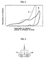
- Fig. 3 is a graph for explaining a comparison of deceleration of an obstruction and history of displacement when the bumper rubber 10 of the embodiment is provided and when a bumper rubber having one elastic portion is provided.
- an experiment history M of the bumper rubber 10 of the embodiment i.e., the bumper rubber 10 provided with the upper elastic portion 14 and the lower elastic portion 15 is shown with a solid line
- an experiment history N of a bumper rubber (comparative example 1) having only the lower elastic portion is shown with a broken line.
- the bumper rubber 10 of the embodiment having the upper elastic portion 14 has reduced deceleration of the obstruction.
- the bumper rubber 10 of the embodiment absorbs the initial impact force F applied to the hood outer panel 1A more effectively than the comparative example 1, and can enhance the absorbing efficiency of the entire impact energy.
- the upper elastic portion 14 is provided with the hollow portion 14E which is crushed and deformed by an impact force input from the hood outer panel 1A, a portion of the hollow portion 14E which is not crushed at the time of deformation can be reduced. As a result, since the deformation stroke of the hood outer panel 1A is increased, the absorbing efficiency of the impact energy can be enhanced correspondingly.
- the opening portion 14T is formed in the hollow portion 14E on the side opposed to the hood outer panel 1A.
- the deformation is not hindered by a lid and thus, the upper elastic portion 14 can be inclined laterally.
- a portion which is not crushed at the time of deformation can be reduced.
- the upper elastic portion 14 is formed into the columnar shape in which its center axis C is positioned in the vertical direction of the vehicle body, the hollow portion 14E is formed into the columnar shape and is coaxially positioned with the impact energy absorbing unit 14 and thus, the thickness of the upper elastic portion 14 in its circumferential direction can be made substantially equal over the entire periphery. As a result, no matter from which direction the impact force F is input, the bumper rubber 10 can be deformed stably.
- the bumper rubber 10 when the bumper rubber 10 is provided at its outer periphery with the spiral groove 12 and it is screwed into the opening 5 of the hood inner panel 1B, equal effect can be exhibited without depending upon the rotation angle at the time of mounting operation and thus, it is unnecessary to enhance the machining precision of the bumper rubber 10 and the productivity can be enhanced.
- the core portion 16 is provided in the load transmitting path extending from the upper elastic portion 14 of the bumper rubber 10 to the hood inner panel 1B. With this configuration, the impact force F is efficiently transmitted to the hood inner panel 1B through the core portion 16, and the function as the bumper rubber 10 can more reliably be exhibited. There is also a merit that the bumper rubber 10 can be arranged on the hood inner panel 1B stably and reliably.
- the inner diameter D of the hollow portion 14E is made greater than the distance L between the core portion 16 and the impact force input end 14a of the upper elastic portion 14.
- the projected absorbing unit 14S projected toward the hood outer panel 1A is provided on the end of the upper elastic portion 14 on the side of the hood outer panel 1A. With this configuration, it becomes easy to adjust the reaction force by the projected absorbing unit 14S. Since the outer diameter of the projected absorbing unit 14S is made smaller than the outer diameter of the other portion of the upper elastic portion 14, it becomes easy to insert the bumper rubber 10 into the opening 5 of the hood inner panel 1B, and it becomes easy to mount the bumper rubber 10 on the hood inner panel 1B by screwing.
- the columnar space 14Ea which is in communication with the hollow portion 14E formed in the upper elastic portion 14 is formed in the projected absorbing unit 14S.
- the hood outer panel 1A deformed by the impact force F is brought into contact with the projected absorbing unit 14S, and a force in the laterally bending direction can be generated in the projected absorbing unit 14S. Since the curved surface R is formed on the outer peripheral end of the tip end of the projected absorbing unit 14S, as shown in Fig. 7 , even if the impact force F is input from various angles into the curved surface R, the laterally bending mode can be generated stable in the projected absorbing unit 14S, and it is possible to more reliably enhance the absorbing efficiency of impact energy.
- the spiral groove 12 formed in the outer side of the upper elastic portion 14 near the core portion 16 is used as the stress concentrating unit that is inclined with respect to the input direction of an impact force.
- a laterally bending mode can stably be generated in the upper elastic portion 14 when the impact force F is input.
- the stress concentrating unit is not limited to the spiral groove 12 and as shown in Fig. 8 , a step portion which is inclined with respect to the center axis C is provided, and a corner K of the step portion can be used as the stress concentrating unit.
- the bumper rubber 10 is mounted on the hood inner panel 1B such that the center axis C of the upper elastic portion 14 and the deformation direction X of the hood outer panel 1A are deviated from each other by the predetermined angle ⁇ .
- the lateral bending is easily generated in the upper elastic portion 14, and a portion which is not crushed when the upper elastic portion 14 is deformed can further be reduced.
- the bumper rubber 10 is mounted such that the inclination angle ⁇ becomes 6° or greater.
- the impact absorber is mounted on the hood inner panel such that the end of the impact absorber projects toward the hood outer panel, and the impact energy absorbing unit is provided closer to the hood outer panel than the hood inner panel of the impact absorber.
- an impact force which is input from the hood outer panel is absorbed by the impact energy absorbing unit.
- a reaction force between the hood outer panel and the hood inner panel can be adjusted and the impact against an obstruction which collides against the hood outer panel can effectively be moderated. That is, the initial impact force applied to the hood outer panel can efficiently be absorbed and the absorbing effect of the entire impact energy can be enhanced.
Landscapes
- Engineering & Computer Science (AREA)
- Mechanical Engineering (AREA)
- Superstructure Of Vehicle (AREA)
Abstract
Description
- This application is based upon and claims the benefit of priority from prior Japanese Patent Application
P2007-271448 filed on October 18,2007 - The present invention relates to a vehicle body front part structure in which an impact absorber is provided on a hood which is formed into a double panel structure comprising a hood outer panel and a hood inner panel.
- Conventionally, as a vehicle body front part structure, there is a known vehicle body front part structure that an impact absorber is provided between a hood and a vehicle body constituent member to absorb impact which is input to the hood, as disclosed in Japanese Patent Application Laid-open No.
2006-520717 - According to the impact absorber of Japanese Patent Application Laid-open No.
2006-520717 - A base end of the case is mounted on the vehicle body constituent member such that the elastic rubber on the tip end opposes to the hood. And the elastic rubber is deformed and the compression spring is compressed, so that excessive impact which is input to the hood can be absorbed.
- However, when such a conventional technique is applied to the hood of the double panel structure including the hood outer panel and the hood inner panel, the impact absorber absorbs only the impact applied to the hood inner panel with which the impact absorber comes into direct contact.
- That is, since this conventional technique does not have a function for absorbing the impact energy in a space between the hood outer panel and the hood inner panel, the initial impact force which is input to the hood outer panel can not be absorbed efficiently and the absorbing efficiency of the entire impact energy is deteriorated.
- Therefore, an object of the present invention is to provide a vehicle body front part structure capable of enhancing the absorbing efficiency of impact energy when a hood is of a double panel structure including a hood outer panel and a hood inner panel.
- The present invention provides a vehicle body front part structure in which a hood including a hood outer panel and a hood inner panel positioned on a side of a back surface of the hood outer panel at a distance from the hood outer panel is provided on an upper portion of a vehicle body constituent member such that the hood can open and close, and an impact absorber is interposed between the hood and the vehicle body constituent member such that the impact absorber abuts against the vehicle body constituent member when the hood is closed, and the invention is most characterized such that the impact absorber is mounted on the hood inner panel such that an end of the impact absorber projects toward the hood outer panel, and an impact which is input to the hood outer panel is absorbed by the impact absorber, and an impact generated when the hood is closed is absorbed by the impact absorber.
-
-
Fig. 1 is a sectional view of relevant parts showing a mounting state of an impact absorber according to an embodiment of the present invention; -
Fig. 2 is an enlarged sectional view of the impact absorber according to the embodiment; -
Fig. 3 is a graph for explaining an effect of the impact absorber according to the embodiment; -
Fig. 4 is an explanatory diagram of a function of a hollow portion provided in an impact energy absorbing unit according to the embodiment; -
Fig. 5 is an explanatory diagram of a function of an opening portion provided in the hollow portion of the impact energy absorbing unit according to the embodiment; -
Fig. 6 is an explanatory diagram of a function created by a diameter of the hollow portion of the impact energy absorbing unit according to the embodiment; -
Fig. 7 is an explanatory diagram of a function when a curved portion having a rounded corner is formed on a projected absorbing unit provided in the impact energy absorbing unit according to the embodiment; and -
Fig. 8 is a sectional view of a bumper rubber showing a modification of a stress concentrating unit that is inclined with respect to an input direction of an impact force according to the embodiment. - An embodiment of the present invention will be explained below with reference to the accompanying drawings.
- An
engine room 3 having an opening at upper part of it is formed at a front part of vehicle. And a hood 1 which can open and close this opening is provided at a front part of vehicle. - A side end of a rear portion of the hood 1 is mounted on a vehicle body through a hinge (not shown). By rotating the hood 1 around a rotation shaft of the hinge extending in a width direction of the vehicle, a closed state of the hood 1 and an opened state of the hood 1 can be switched. In a vehicle having an engine provided on the side of a rear portion of the vehicle not on the side of a front portion of the vehicle, the hood 1 covers an upper side of a front compartment instead of the
engine room 3. - The opening edge of the
engine room 3 is provided in an upper portion of aradiator core support 4, and the opening edge is formed of a vehiclebody constituent member 2 such as anupper rail 4a extending laterally at a front end in the longitudinal direction of the vehicle. - The hood 1 is provided on the upper portion of the vehicle
body constituent member 2 such as theupper rail 4a such that the hood 1 can open and close. - The hood 1 includes a hood
outer panel 1A and a hoodinner panel 1B which is positioned at a distance from a back surface of the hoodouter panel 1A. - Further, a bumper rubber (impact absorber) 10 is interposed between the
upper rail 4a of theradiator core support 4 and the hoodouter panel 1A for absorbing an impact generated when the hood 1 is closed. - In the present embodiment, the
bumper rubber 10 is positioned at a central portion of the hood 1 and theupper rail 4a in the width direction of the vehicle, and anend 10a of thebumper rubber 10 is mounted on the hoodinner panel 1B such that theend 10a projects toward the hoodouter panel 1A. - Specifically, as shown in
Fig. 2 , thebumper rubber 10 is formed into a columnar shape such that anelastic body 11 such as rubber and soft synthetic resin is formed as a main body. Aspiral groove 12 is formed in an outer periphery of thebumper rubber 10, and thespiral groove 12 is threadedly engaged with and screwed into anopening 5 formed in the hoodinner panel 1B, thereby fixing thebumper rubber 10 to theopening 5 of the hoodinner panel 1B. In the present embodiment, a central portion of thebumper rubber 10 in the axial direction (vertical direction inFig. 2 ) is amounting portion 13 with respect to the hoodinner panel 1B. - By mounting the
bumper rubber 10 on the hoodinner panel 1B such that theend 10a of thebumper rubber 10 projects toward the hoodouter panel 1A in this manner, an impact which is input to the hoodouter panel 1A is absorbed by thebumper rubber 10, and an impact generated when the hood 1 is closed is absorbed. - In the present embodiment, the
end 10a of thebumper rubber 10 is provided with an upper elastic portion (impact energy absorbing unit) 14 which absorbs an impact input from the hoodouter panel 1A. - Further, in the present embodiment, a lower
elastic portion 15 as an impact energy absorbing unit that absorbs an impact input from the hoodinner panel 1B is provided on a part of thebumper rubber 10 closer to theupper rail 4a than themounting portion 13, i.e., on anend 10b of thebumper rubber 10 opposite from theend 10a (lower side inFig. 2 ). - The
bumper rubber 10 is mounted such that aprojecting tip end 15a of the lowerelastic portion 15 abuts against theupper rail 4a when the hood 1 is closed. - The upper
elastic portion 14 and the lowerelastic portion 15 are made of material suitable for absorbing impact energy, such as elastic body, viscous plastic body, elastic plastic body made of rubber or soft synthetic resin or material having the same function. - When the hood 1 is closed, as shown in
Fig. 1 , aweather strip 6 mounted on a tip end of abracket 4b extending rearward of the vehicle from theupper rail 4a comes into contact with the hoodinner panel 1B under pressure so that liquid-tightness and sound insulation can be ensured. - In the present embodiment, the upper
elastic portion 14 has ahollow portion 14E which can be crushed and deformed by an impact force input from the hoodouter panel 1A. And anopening portion 14T is formed in thehollow portion 14E on a side opposed to the hoodouter panel 1A. The upperelastic portion 14 is formed into a columnar shape in which its center axis C is oriented in the vertical direction of the vehicle body, thehollow portion 14E is formed into a columnar shape, and the upperelastic portion 14 and thehollow portion 14E are coaxially positioned. - A core portion (load-receiving portion) 16 is provided in a load transmitting path extending from the upper
elastic portion 14 of thebumper rubber 10 to the hoodinner panel 1B. - In the present embodiment, the
core portion 16 is formed into a thick cylindrical shape, a lower end of thecore portion 16 which comes into contact with the lowerelastic portion 15 is provided with a large-diameter portion 16a. Thecore portion 16 is coaxially embedded into thebumper rubber 10 and is vulcanized and adhered. - Here, a width of the
hollow portion 14E in a direction intersecting with an impact input direction (vertical direction) at right angles, i.e., an inner diameter of thehollow portion 14E is defined as D. And a distance between the impactforce input end 14a of the upperelastic portion 14 and thecore portion 16 is defined as L. In this condition, thehollow portion 14E is formed such that the inner diameter D becomes greater than the distance L between the impactforce input end 14a and thecore portion 16. - A projected absorbing
unit 14S projects from an end of the upperelastic portion 14 on the side of the hoodouter panel 1A toward the hoodouter panel 1A. An outer diameter of the projected absorbingunit 14S is smaller than other portions of the upperelastic portion 14. The projected absorbingunit 14S is formed with a columnar space 14Ea which is in communication with thehollow portion 14E formed in the upperelastic portion 14. In the present embodiment, as shown inFig. 2 , not only the columnar space 14Ea and thehollow portion 14E, but also thehollow portion 14E and a hollow portion in thecore portion 16, and the hollow portion of thecore portion 16 and a hollow portion of the lowerelastic portion 15 are also in communication with each other. - A curved portion R is formed on an outer peripheral end of the tip end of the projected absorbing
unit 14S. The curved portion R has a rounded corner. - In the present embodiment, the
spiral groove 12 formed in the outer side of the upperelastic portion 14 near thecore portion 16 is used as a stress concentrating unit that is inclined with respect to the input direction of an impact force. - As shown in
Fig. 1 , thebumper rubber 10 is mounted on the hoodinner panel 1B such that the center axis C of the upperelastic portion 14 and the deformation direction X of the hoodouter panel 1A are deviated from each other by a predetermined angle α. - According to this structure, when some article collides against the hood 1, if an impact force F more than a predetermined value is input to the
bumper rubber 10 from the hood 1, the following operation is carried out. - First, the hood
outer panel 1A is plastically deformed downward in a convex form. If the hoodouter panel 1A is deformed by the impact force F to some extent, the deformed hoodouter panel 1A secondary collides against the upperelastic portion 14 of thebumper rubber 10. As a result, the upperelastic portion 14 is deformed by the hoodouter panel 1A, and the impact force F which is input from the hoodouter panel 1A is absorbed. The lowerelastic portion 15 which abuts against theupper rail 4a is deformed by a load which is not absorbed by the upperelastic portion 14 and which is transmitted to the lowerelastic portion 15, and this load is absorbed. The upperelastic portion 14 and the lowerelastic portion 15 absorb the impact energy in this manner, and the entire absorbing efficiency of impact energy is enhanced. - According to the present embodiment, since the
end 10a of thebumper rubber 10 is provided with the upperelastic portion 14, the upperelastic portion 14 can be deformed by the hoodouter panel 1A which secondary collides against the upperelastic portion 14 when the impact force F is input to the hoodouter panel 1A, and the impact force F which is input from the hoodouter panel 1A can be absorbed. - That is, since the
end 10a of thebumper rubber 10 is provided with the upperelastic portion 14, impact energy can be absorbed between the hoodouter panel 1A and the hoodinner panel 1B. - As a result, if the rigidity of the upper
elastic portion 14 is appropriately set, a reaction force between the hoodouter panel 1A and the hoodinner panel 1B can be adjusted. - Further, according to the present embodiment, since the
end 10b of thebumper rubber 10 is provided with the lowerelastic portion 15, the lowerelastic portion 15 can be deformed by a load transmitted to the lowerelastic portion 15 from the hoodinner panel 1B and an impact energy can be absorbed. - The effect obtained when the
bumper rubber 10 is provided with the upperelastic portion 14 and the lowerelastic portion 15 will be explained based onFig. 3 . -
Fig. 3 is a graph for explaining a comparison of deceleration of an obstruction and history of displacement when thebumper rubber 10 of the embodiment is provided and when a bumper rubber having one elastic portion is provided. InFig. 3 , an experiment history M of thebumper rubber 10 of the embodiment, i.e., thebumper rubber 10 provided with the upperelastic portion 14 and the lowerelastic portion 15 is shown with a solid line, and an experiment history N of a bumper rubber (comparative example 1) having only the lower elastic portion is shown with a broken line. As apparent fromFig. 3 , as compared with the comparative example 1, it is understood that thebumper rubber 10 of the embodiment having the upperelastic portion 14 has reduced deceleration of the obstruction. - That is, the
bumper rubber 10 of the embodiment absorbs the initial impact force F applied to the hoodouter panel 1A more effectively than the comparative example 1, and can enhance the absorbing efficiency of the entire impact energy. - When the
bumper rubber 10 is provided with the upperelastic portion 14 and the lowerelastic portion 15, an impact of an obstruction which collides against the hoodouter panel 1A can effectively be moderated. - Further, according to the present embodiment, since the upper
elastic portion 14 is provided with thehollow portion 14E which is crushed and deformed by an impact force input from the hoodouter panel 1A, a portion of thehollow portion 14E which is not crushed at the time of deformation can be reduced. As a result, since the deformation stroke of the hoodouter panel 1A is increased, the absorbing efficiency of the impact energy can be enhanced correspondingly. - When the upper
elastic portion 14 and the lowerelastic portion 15 are integrally formed together using the same material, it becomes easy to adjust the rigidity by changing the diameter of thehollow portion 14E. - Furthermore, according to the present embodiment, the
opening portion 14T is formed in thehollow portion 14E on the side opposed to the hoodouter panel 1A. With this configuration, as shown inFig. 5 , the deformation is not hindered by a lid and thus, the upperelastic portion 14 can be inclined laterally. Thus, as compared with a case having a lid as shown inFig. 4 , a portion which is not crushed at the time of deformation can be reduced. - Further, according to the present embodiment, the upper
elastic portion 14 is formed into the columnar shape in which its center axis C is positioned in the vertical direction of the vehicle body, thehollow portion 14E is formed into the columnar shape and is coaxially positioned with the impactenergy absorbing unit 14 and thus, the thickness of the upperelastic portion 14 in its circumferential direction can be made substantially equal over the entire periphery. As a result, no matter from which direction the impact force F is input, thebumper rubber 10 can be deformed stably. Particularly as in the present embodiment, when thebumper rubber 10 is provided at its outer periphery with thespiral groove 12 and it is screwed into theopening 5 of the hoodinner panel 1B, equal effect can be exhibited without depending upon the rotation angle at the time of mounting operation and thus, it is unnecessary to enhance the machining precision of thebumper rubber 10 and the productivity can be enhanced. - The
core portion 16 is provided in the load transmitting path extending from the upperelastic portion 14 of thebumper rubber 10 to the hoodinner panel 1B. With this configuration, the impact force F is efficiently transmitted to the hoodinner panel 1B through thecore portion 16, and the function as thebumper rubber 10 can more reliably be exhibited. There is also a merit that thebumper rubber 10 can be arranged on the hoodinner panel 1B stably and reliably. - The inner diameter D of the
hollow portion 14E is made greater than the distance L between thecore portion 16 and the impactforce input end 14a of the upperelastic portion 14. With this configuration, as shown inFig. 6 , the cylindrical upperelastic portion 14 can be folded into thehollow portion 14E efficiently, and a portion which is not crushed at the time of deformation can further be reduced. - The projected absorbing
unit 14S projected toward the hoodouter panel 1A is provided on the end of the upperelastic portion 14 on the side of the hoodouter panel 1A. With this configuration, it becomes easy to adjust the reaction force by the projected absorbingunit 14S. Since the outer diameter of the projected absorbingunit 14S is made smaller than the outer diameter of the other portion of the upperelastic portion 14, it becomes easy to insert thebumper rubber 10 into theopening 5 of the hoodinner panel 1B, and it becomes easy to mount thebumper rubber 10 on the hoodinner panel 1B by screwing. - The columnar space 14Ea which is in communication with the
hollow portion 14E formed in the upperelastic portion 14 is formed in the projected absorbingunit 14S. With this configuration, a portion which is not crushed when the upperelastic portion 14 is deformed can be reduced, and the reaction force can easily be adjusted. Particularly, according to the present embodiment, since the lowerelastic portion 15 is also formed with the hollow portion, the reaction force can easily be adjusted more, and the portion which is not crushed can be reduced more. - According to the present embodiment, since the curve surface R having the rounded corner is formed on the outer peripheral end of the tip end of the projected absorbing
unit 14S, the hoodouter panel 1A deformed by the impact force F is brought into contact with the projected absorbingunit 14S, and a force in the laterally bending direction can be generated in the projected absorbingunit 14S. Since the curved surface R is formed on the outer peripheral end of the tip end of the projected absorbingunit 14S, as shown inFig. 7 , even if the impact force F is input from various angles into the curved surface R, the laterally bending mode can be generated stable in the projected absorbingunit 14S, and it is possible to more reliably enhance the absorbing efficiency of impact energy. - According to the present embodiment, the
spiral groove 12 formed in the outer side of the upperelastic portion 14 near thecore portion 16 is used as the stress concentrating unit that is inclined with respect to the input direction of an impact force. With this conf iguration, a laterally bending mode can stably be generated in the upperelastic portion 14 when the impact force F is input. - The stress concentrating unit is not limited to the
spiral groove 12 and as shown inFig. 8 , a step portion which is inclined with respect to the center axis C is provided, and a corner K of the step portion can be used as the stress concentrating unit. - According to the present embodiment, the
bumper rubber 10 is mounted on the hoodinner panel 1B such that the center axis C of the upperelastic portion 14 and the deformation direction X of the hoodouter panel 1A are deviated from each other by the predetermined angle α. Thus, the lateral bending is easily generated in the upperelastic portion 14, and a portion which is not crushed when the upperelastic portion 14 is deformed can further be reduced. It is preferable that thebumper rubber 10 is mounted such that the inclination angle α becomes 6° or greater. With this configuration, a sine value with respect to the inclination angle α becomes 0.1 or greater (sin 6° ≈0.1), and a force in the lateral bending direction becomes 10% or greater of the input impact force F, and the upperelastic portion 14 can effectively be bent. - As described above, according to the present invention, the impact absorber is mounted on the hood inner panel such that the end of the impact absorber projects toward the hood outer panel, and the impact energy absorbing unit is provided closer to the hood outer panel than the hood inner panel of the impact absorber. With this configuration, an impact force which is input from the hood outer panel is absorbed by the impact energy absorbing unit. Thus, a reaction force between the hood outer panel and the hood inner panel can be adjusted and the impact against an obstruction which collides against the hood outer panel can effectively be moderated. That is, the initial impact force applied to the hood outer panel can efficiently be absorbed and the absorbing effect of the entire impact energy can be enhanced.
- While the embodiment of the present invention has been described above, the invention is not limited to the above embodiment and changes and modifications can be made within the scope of the gist of the present invention.
Claims (12)
- A vehicle body front part structure comprising:a hood (1) which is provided on an upper portion of a vehicle body constituent member (2) such that the hood (1) can open and close; including:a hood outer panel (1A); anda hood inner panel (1B) arranged on a side of a back surface of the hood outer panel (1A) at a distance from the hood outer panel (1A); andan impact absorber (10) interposed between the hood (1) and the vehicle body constituent member (2) such that the impact absorber (10) abuts against the vehicle body constituent member (2) when the hood (1) is closed, whereinthe impact absorber (10) is mounted on the hood inner panel (1B) such that an end of the impact absorber (10) projects toward the hood outer panel (1A), andan impact which is input to the hood outer panel (1A) is absorbed by the impact absorber (10), and an impact generated when the hood (1) is closed is absorbed by the impact absorber (10).
- The vehicle body front part structure according to claim 1, wherein an end of the impact absorber (10) on a side of the hood outer panel (1A) is provided with an impact energy absorbing unit (14) that absorbs an impact which is input into the hood outer panel (1A).
- The vehicle body front part structure according to claim 2, wherein the impact energy absorbing unit (14) includes a hollow portion (14E) which is crushed and deformed by an impact force input from the hood outer panel (1A).
- The vehicle body front part structure according to claim 3, wherein an opening portion (14T) is formed in the hollow portion (14E) on a side opposed to the hood outer panel (1A).
- The vehicle body front part structure according to claims 3 or 4, wherein the impact energy absorbing unit (14) is formed into a columnar shape in which a center axis (C) thereof is positioned in a vertical direction of a vehicle body, and the hollow portion (14E) is formed into a columnar shape and is coaxially positioned with the impact energy absorbing unit (14).
- The vehicle body front part structure according to any one of claims 2 to 5, wherein a load transmitting path extending from the impact energy absorbing unit (14) to the hood inner panel (1B) is provided with a load-receiving portion (16).
- The vehicle body front part structure according to claim 6, wherein a width of the hollow portion (14E) in a direction intersecting with an input direction of an impact force at right angles is greater than a distance between an impact force input end (14a) of the impact energy absorbing unit (14) and the load-receiving portion (16).
- The vehicle body front part structure according to any one of claims 2 to 7, wherein an end of the impact energy absorbing unit (14) on a side of the hood outer panel (1A) is provided with a projected absorbing unit (14S) that projects toward the hood outer panel (1A).
- The vehicle body front part structure according to claim 8, wherein the projected absorbing unit (14S) includes a columnar space (14Ea) which is in communication with the hollow portion (14E).
- The vehicle body front part structure according to claims 8 or 9, wherein an outer peripheral side end of the projected absorbing unit (14S) is formed with a curved portion (R) having a rounded corner.
- The vehicle body front part structure according to any one of claims 6 to 10, wherein a stress concentrating unit (12) that is inclined with respect to an input direction of an impact force is provided on an outer side of the impact energy absorbing unit (14) near the load-receiving portion (16).
- The vehicle body front part structure according to claim 5, wherein the impact absorber (10) is mounted on the hood inner panel (1A) such that a center axial (C) direction of the impact energy absorbing unit (14) and a deforming direction (X) of the hood outer panel (1A) are different from each other.
Applications Claiming Priority (1)
| Application Number | Priority Date | Filing Date | Title |
|---|---|---|---|
| JP2007271448A JP4985305B2 (en) | 2007-10-18 | 2007-10-18 | Body front structure |
Publications (2)
| Publication Number | Publication Date |
|---|---|
| EP2050631A1 true EP2050631A1 (en) | 2009-04-22 |
| EP2050631B1 EP2050631B1 (en) | 2011-12-14 |
Family
ID=40254508
Family Applications (1)
| Application Number | Title | Priority Date | Filing Date |
|---|---|---|---|
| EP08017990A Active EP2050631B1 (en) | 2007-10-18 | 2008-10-14 | Vehicle body front part structure |
Country Status (4)
| Country | Link |
|---|---|
| US (1) | US7878578B2 (en) |
| EP (1) | EP2050631B1 (en) |
| JP (1) | JP4985305B2 (en) |
| CN (1) | CN101412410B (en) |
Families Citing this family (12)
| Publication number | Priority date | Publication date | Assignee | Title |
|---|---|---|---|---|
| US7690722B2 (en) * | 2007-05-21 | 2010-04-06 | Honda Motor Co., Ltd. | Energy absorbing vehicle hood stopper assembly |
| GB2503496B (en) * | 2012-06-27 | 2017-09-13 | Aston Martin Lagonda Ltd | Vehicle assembly |
| KR101449263B1 (en) * | 2013-04-02 | 2014-10-08 | 현대자동차주식회사 | Hood Over Slam Bumper Assembly |
| JP6263074B2 (en) * | 2014-04-18 | 2018-01-17 | スズキ株式会社 | Cushion structure of vehicle hood |
| US9718434B2 (en) * | 2015-01-21 | 2017-08-01 | GM Global Technology Operations LLC | Tunable energy absorbers |
| US9656627B2 (en) * | 2015-10-06 | 2017-05-23 | Ford Global Technologies, Llc | Hood bumpers to absorb loading |
| US9950744B2 (en) | 2016-03-24 | 2018-04-24 | Toyota Motor Engineering & Manufacturing North America, Inc. | Vehicle hood assemblies including a reinforcement strap and vehicles including the same |
| US10150444B1 (en) * | 2017-09-15 | 2018-12-11 | Ford Global Technologies, Llc | Frangible bump stop support |
| JP7070365B2 (en) * | 2018-11-21 | 2022-05-18 | トヨタ自動車株式会社 | Vehicle front structure |
| GB201820560D0 (en) | 2018-12-17 | 2019-01-30 | Aston Martin Lagonda Ltd | Assemblies for engines |
| DE102021131818A1 (en) * | 2021-12-02 | 2023-06-07 | Bbp Kunststoffwerk Marbach Baier Gmbh | Cover part with integrated stop buffer and its manufacture |
| JP2024033162A (en) * | 2022-08-30 | 2024-03-13 | マツダ株式会社 | How to assemble the front part of the vehicle |
Citations (4)
| Publication number | Priority date | Publication date | Assignee | Title |
|---|---|---|---|---|
| JPS596158A (en) * | 1982-06-30 | 1984-01-13 | Nissan Motor Co Ltd | Hood damper |
| US5706908A (en) | 1994-04-18 | 1998-01-13 | Nissan Motor Co., Ltd. | Front upper structure of automotive vehicle |
| EP1642786A2 (en) * | 2004-09-30 | 2006-04-05 | Mazda Motor Corporation | Hood stopper structure for automobile |
| JP2006520717A (en) | 2003-03-17 | 2006-09-14 | ルノー・エス・アー・エス | Shock absorbing support device for automobile |
Family Cites Families (13)
| Publication number | Priority date | Publication date | Assignee | Title |
|---|---|---|---|---|
| US4653968A (en) * | 1980-08-25 | 1987-03-31 | Illinois Tool Works, Inc. | Adjustable abutment assembly |
| JPS6416982U (en) | 1987-07-16 | 1989-01-27 | ||
| JPS6442983U (en) * | 1987-09-10 | 1989-03-15 | ||
| JPH0423584U (en) | 1990-06-21 | 1992-02-26 | ||
| JP3120656B2 (en) * | 1994-04-18 | 2000-12-25 | 日産自動車株式会社 | Car hood structure |
| US5682667A (en) * | 1996-04-10 | 1997-11-04 | The Budd Company | Method for preventing damage to an overslam bumper pocket |
| KR19980027994A (en) * | 1996-10-18 | 1998-07-15 | 박병재 | Hood Overslam Bumper Shock Absorber |
| KR100320835B1 (en) * | 1999-12-29 | 2002-01-18 | 이계안 | Vibration protecting structure of tail gate for automobile |
| EP1595755B1 (en) * | 2004-05-12 | 2008-02-27 | Compagnie Plastic Omnium | Support for a stop for a vehicle front hood |
| JP4857595B2 (en) * | 2005-04-27 | 2012-01-18 | マツダ株式会社 | Front body structure of automobile |
| DE102005055071B4 (en) * | 2005-11-18 | 2008-10-23 | Itw Automotive Products Gmbh & Co. Kg | Bump stop for a bonnet of automobiles |
| US7690722B2 (en) * | 2007-05-21 | 2010-04-06 | Honda Motor Co., Ltd. | Energy absorbing vehicle hood stopper assembly |
| US7758106B2 (en) * | 2008-02-02 | 2010-07-20 | Ford Global Technologies, Llc | Self-adjusting automotive radiator grille support |
-
2007
- 2007-10-18 JP JP2007271448A patent/JP4985305B2/en active Active
-
2008
- 2008-09-10 US US12/207,993 patent/US7878578B2/en active Active
- 2008-10-14 EP EP08017990A patent/EP2050631B1/en active Active
- 2008-10-16 CN CN2008101702650A patent/CN101412410B/en active Active
Patent Citations (4)
| Publication number | Priority date | Publication date | Assignee | Title |
|---|---|---|---|---|
| JPS596158A (en) * | 1982-06-30 | 1984-01-13 | Nissan Motor Co Ltd | Hood damper |
| US5706908A (en) | 1994-04-18 | 1998-01-13 | Nissan Motor Co., Ltd. | Front upper structure of automotive vehicle |
| JP2006520717A (en) | 2003-03-17 | 2006-09-14 | ルノー・エス・アー・エス | Shock absorbing support device for automobile |
| EP1642786A2 (en) * | 2004-09-30 | 2006-04-05 | Mazda Motor Corporation | Hood stopper structure for automobile |
Also Published As
| Publication number | Publication date |
|---|---|
| EP2050631B1 (en) | 2011-12-14 |
| US7878578B2 (en) | 2011-02-01 |
| JP4985305B2 (en) | 2012-07-25 |
| JP2009096393A (en) | 2009-05-07 |
| CN101412410A (en) | 2009-04-22 |
| CN101412410B (en) | 2011-09-14 |
| US20090102239A1 (en) | 2009-04-23 |
Similar Documents
| Publication | Publication Date | Title |
|---|---|---|
| EP2050631B1 (en) | Vehicle body front part structure | |
| JP6116334B2 (en) | Gas pressure actuator and method for assembling the same | |
| US7975797B2 (en) | Vehicle pop up hood apparatus | |
| US8672305B2 (en) | Work apparatus | |
| US20070234527A1 (en) | Cushioning clip | |
| CN101782123B (en) | Cushion clip | |
| CN105339703A (en) | Vibration isolation device | |
| JP6621811B2 (en) | Energy absorption module for vehicle steering column assembly | |
| CN105365720B (en) | Adaptive energy absorber for vehicle | |
| CN107532581A (en) | Refrigerant compressor | |
| US10112562B2 (en) | Deformation element arrangement and motor vehicle having a deformation element arrangement | |
| WO2015072293A1 (en) | Gas-pressure-type actuator | |
| CN108608838B (en) | Door structure for vehicle | |
| US20160355147A1 (en) | Trim dampening fastener | |
| WO2005123484A1 (en) | Shock absorbing device at stroke end of rack | |
| JP7131322B2 (en) | door service hole cover | |
| CN115162879B (en) | Buffer device and automobile comprising same | |
| JP5016567B2 (en) | Cushion body | |
| JP4291722B2 (en) | Cowl top cover | |
| JP4492572B2 (en) | Support structure for vehicle doors | |
| CN101468629B (en) | An energy absorbing device and a car door with the device | |
| CN107524364A (en) | Bolster and restraint assembly for structural member | |
| CN223835694U (en) | Limiting mechanisms for the front of the cab and vehicles | |
| WO2021075311A1 (en) | Vibration suppressing device | |
| JP5554623B2 (en) | Car cabin side wall structure |
Legal Events
| Date | Code | Title | Description |
|---|---|---|---|
| PUAI | Public reference made under article 153(3) epc to a published international application that has entered the european phase |
Free format text: ORIGINAL CODE: 0009012 |
|
| 17P | Request for examination filed |
Effective date: 20081014 |
|
| AK | Designated contracting states |
Kind code of ref document: A1 Designated state(s): AT BE BG CH CY CZ DE DK EE ES FI FR GB GR HR HU IE IS IT LI LT LU LV MC MT NL NO PL PT RO SE SI SK TR |
|
| AX | Request for extension of the european patent |
Extension state: AL BA MK RS |
|
| 17Q | First examination report despatched |
Effective date: 20091019 |
|
| AKX | Designation fees paid |
Designated state(s): DE FR GB |
|
| GRAP | Despatch of communication of intention to grant a patent |
Free format text: ORIGINAL CODE: EPIDOSNIGR1 |
|
| GRAS | Grant fee paid |
Free format text: ORIGINAL CODE: EPIDOSNIGR3 |
|
| GRAA | (expected) grant |
Free format text: ORIGINAL CODE: 0009210 |
|
| AK | Designated contracting states |
Kind code of ref document: B1 Designated state(s): DE FR GB |
|
| REG | Reference to a national code |
Ref country code: GB Ref legal event code: FG4D |
|
| REG | Reference to a national code |
Ref country code: DE Ref legal event code: R096 Ref document number: 602008011912 Country of ref document: DE Effective date: 20120308 |
|
| PLBE | No opposition filed within time limit |
Free format text: ORIGINAL CODE: 0009261 |
|
| STAA | Information on the status of an ep patent application or granted ep patent |
Free format text: STATUS: NO OPPOSITION FILED WITHIN TIME LIMIT |
|
| 26N | No opposition filed |
Effective date: 20120917 |
|
| REG | Reference to a national code |
Ref country code: DE Ref legal event code: R097 Ref document number: 602008011912 Country of ref document: DE Effective date: 20120917 |
|
| REG | Reference to a national code |
Ref country code: FR Ref legal event code: PLFP Year of fee payment: 9 |
|
| REG | Reference to a national code |
Ref country code: FR Ref legal event code: PLFP Year of fee payment: 10 |
|
| REG | Reference to a national code |
Ref country code: FR Ref legal event code: PLFP Year of fee payment: 11 |
|
| REG | Reference to a national code |
Ref country code: DE Ref legal event code: R084 Ref document number: 602008011912 Country of ref document: DE |
|
| REG | Reference to a national code |
Ref country code: GB Ref legal event code: 746 Effective date: 20230922 |
|
| PGFP | Annual fee paid to national office [announced via postgrant information from national office to epo] |
Ref country code: GB Payment date: 20250923 Year of fee payment: 18 |
|
| PGFP | Annual fee paid to national office [announced via postgrant information from national office to epo] |
Ref country code: FR Payment date: 20250923 Year of fee payment: 18 |
|
| PGFP | Annual fee paid to national office [announced via postgrant information from national office to epo] |
Ref country code: DE Payment date: 20250923 Year of fee payment: 18 |