EP2050596A1 - Electronic air supply device - Google Patents
Electronic air supply device Download PDFInfo
- Publication number
- EP2050596A1 EP2050596A1 EP20080014327 EP08014327A EP2050596A1 EP 2050596 A1 EP2050596 A1 EP 2050596A1 EP 20080014327 EP20080014327 EP 20080014327 EP 08014327 A EP08014327 A EP 08014327A EP 2050596 A1 EP2050596 A1 EP 2050596A1
- Authority
- EP
- European Patent Office
- Prior art keywords
- compressed air
- pressure
- circuits
- valve
- service brake
- Prior art date
- Legal status (The legal status is an assumption and is not a legal conclusion. Google has not performed a legal analysis and makes no representation as to the accuracy of the status listed.)
- Granted
Links
- 230000000903 blocking effect Effects 0.000 claims abstract description 4
- 238000011144 upstream manufacturing Methods 0.000 claims abstract description 4
- 230000015556 catabolic process Effects 0.000 abstract 1
- 230000002401 inhibitory effect Effects 0.000 abstract 1
- 239000000725 suspension Substances 0.000 description 13
- 230000005283 ground state Effects 0.000 description 4
- 238000004891 communication Methods 0.000 description 2
- 230000001105 regulatory effect Effects 0.000 description 2
- 244000037459 secondary consumers Species 0.000 description 2
- 238000004378 air conditioning Methods 0.000 description 1
- 238000010276 construction Methods 0.000 description 1
- 125000004122 cyclic group Chemical class 0.000 description 1
- 239000002274 desiccant Substances 0.000 description 1
- 238000010586 diagram Methods 0.000 description 1
- 230000008929 regeneration Effects 0.000 description 1
- 238000011069 regeneration method Methods 0.000 description 1
Images
Classifications
-
- B—PERFORMING OPERATIONS; TRANSPORTING
- B60—VEHICLES IN GENERAL
- B60G—VEHICLE SUSPENSION ARRANGEMENTS
- B60G17/00—Resilient suspensions having means for adjusting the spring or vibration-damper characteristics, for regulating the distance between a supporting surface and a sprung part of vehicle or for locking suspension during use to meet varying vehicular or surface conditions, e.g. due to speed or load
- B60G17/02—Spring characteristics, e.g. mechanical springs and mechanical adjusting means
- B60G17/04—Spring characteristics, e.g. mechanical springs and mechanical adjusting means fluid spring characteristics
- B60G17/052—Pneumatic spring characteristics
- B60G17/0523—Regulating distributors or valves for pneumatic springs
-
- B—PERFORMING OPERATIONS; TRANSPORTING
- B60—VEHICLES IN GENERAL
- B60G—VEHICLE SUSPENSION ARRANGEMENTS
- B60G17/00—Resilient suspensions having means for adjusting the spring or vibration-damper characteristics, for regulating the distance between a supporting surface and a sprung part of vehicle or for locking suspension during use to meet varying vehicular or surface conditions, e.g. due to speed or load
- B60G17/015—Resilient suspensions having means for adjusting the spring or vibration-damper characteristics, for regulating the distance between a supporting surface and a sprung part of vehicle or for locking suspension during use to meet varying vehicular or surface conditions, e.g. due to speed or load the regulating means comprising electric or electronic elements
- B60G17/018—Resilient suspensions having means for adjusting the spring or vibration-damper characteristics, for regulating the distance between a supporting surface and a sprung part of vehicle or for locking suspension during use to meet varying vehicular or surface conditions, e.g. due to speed or load the regulating means comprising electric or electronic elements characterised by the use of a specific signal treatment or control method
- B60G17/0185—Resilient suspensions having means for adjusting the spring or vibration-damper characteristics, for regulating the distance between a supporting surface and a sprung part of vehicle or for locking suspension during use to meet varying vehicular or surface conditions, e.g. due to speed or load the regulating means comprising electric or electronic elements characterised by the use of a specific signal treatment or control method for failure detection
-
- B—PERFORMING OPERATIONS; TRANSPORTING
- B60—VEHICLES IN GENERAL
- B60T—VEHICLE BRAKE CONTROL SYSTEMS OR PARTS THEREOF; BRAKE CONTROL SYSTEMS OR PARTS THEREOF, IN GENERAL; ARRANGEMENT OF BRAKING ELEMENTS ON VEHICLES IN GENERAL; PORTABLE DEVICES FOR PREVENTING UNWANTED MOVEMENT OF VEHICLES; VEHICLE MODIFICATIONS TO FACILITATE COOLING OF BRAKES
- B60T17/00—Component parts, details, or accessories of power brake systems not covered by groups B60T8/00, B60T13/00 or B60T15/00, or presenting other characteristic features
- B60T17/002—Air treatment devices
- B60T17/004—Draining and drying devices
-
- B—PERFORMING OPERATIONS; TRANSPORTING
- B60—VEHICLES IN GENERAL
- B60T—VEHICLE BRAKE CONTROL SYSTEMS OR PARTS THEREOF; BRAKE CONTROL SYSTEMS OR PARTS THEREOF, IN GENERAL; ARRANGEMENT OF BRAKING ELEMENTS ON VEHICLES IN GENERAL; PORTABLE DEVICES FOR PREVENTING UNWANTED MOVEMENT OF VEHICLES; VEHICLE MODIFICATIONS TO FACILITATE COOLING OF BRAKES
- B60T17/00—Component parts, details, or accessories of power brake systems not covered by groups B60T8/00, B60T13/00 or B60T15/00, or presenting other characteristic features
- B60T17/02—Arrangements of pumps or compressors, or control devices therefor
-
- B—PERFORMING OPERATIONS; TRANSPORTING
- B60—VEHICLES IN GENERAL
- B60T—VEHICLE BRAKE CONTROL SYSTEMS OR PARTS THEREOF; BRAKE CONTROL SYSTEMS OR PARTS THEREOF, IN GENERAL; ARRANGEMENT OF BRAKING ELEMENTS ON VEHICLES IN GENERAL; PORTABLE DEVICES FOR PREVENTING UNWANTED MOVEMENT OF VEHICLES; VEHICLE MODIFICATIONS TO FACILITATE COOLING OF BRAKES
- B60T17/00—Component parts, details, or accessories of power brake systems not covered by groups B60T8/00, B60T13/00 or B60T15/00, or presenting other characteristic features
- B60T17/18—Safety devices; Monitoring
- B60T17/22—Devices for monitoring or checking brake systems; Signal devices
- B60T17/221—Procedure or apparatus for checking or keeping in a correct functioning condition of brake systems
-
- B—PERFORMING OPERATIONS; TRANSPORTING
- B60—VEHICLES IN GENERAL
- B60G—VEHICLE SUSPENSION ARRANGEMENTS
- B60G2400/00—Indexing codes relating to detected, measured or calculated conditions or factors
- B60G2400/50—Pressure
- B60G2400/51—Pressure in suspension unit
- B60G2400/512—Pressure in suspension unit in spring
- B60G2400/5122—Fluid spring
- B60G2400/51222—Pneumatic
-
- B—PERFORMING OPERATIONS; TRANSPORTING
- B60—VEHICLES IN GENERAL
- B60G—VEHICLE SUSPENSION ARRANGEMENTS
- B60G2500/00—Indexing codes relating to the regulated action or device
- B60G2500/02—Supply or exhaust flow rates; Pump operation
-
- B—PERFORMING OPERATIONS; TRANSPORTING
- B60—VEHICLES IN GENERAL
- B60G—VEHICLE SUSPENSION ARRANGEMENTS
- B60G2600/00—Indexing codes relating to particular elements, systems or processes used on suspension systems or suspension control systems
- B60G2600/02—Retarders, delaying means, dead zones, threshold values, cut-off frequency, timer interruption
-
- B—PERFORMING OPERATIONS; TRANSPORTING
- B60—VEHICLES IN GENERAL
- B60G—VEHICLE SUSPENSION ARRANGEMENTS
- B60G2600/00—Indexing codes relating to particular elements, systems or processes used on suspension systems or suspension control systems
- B60G2600/08—Failure or malfunction detecting means
Definitions
- the invention relates to an electronic air treatment system for equipped with an air suspension system vehicles according to the preamble of claim 1.
- an air compressor is known, from the output to supply the compressed air system leads a delivery line to an air dryer.
- the delivery line is branched on the output side of the air dryer in leading to at least two load circuits line branches.
- the pressure in the consumer circuits can be monitored by pressure sensors. It is provided an electronic control unit to which the pressure sensors are connected.
- the consumer circuits can be separated from the compressed air supply by a switchable from the programmable control electronics, lying in the respective delivery line branch locking member.
- the locking member is formed by an overflow valve, which are switchable by an additional actuating means in a position blocking the associated line branch.
- the actuating means may be a pneumatic, electromagnetic or electromechanical actuating means.
- a disadvantage of this known compressed air supply device is that for each overflow valve its own actuating means, for example. Solenoid valve, is provided for actuation.
- a pneumatic vehicle braking system comprising a compressor, at least one air consumer circuit, for example service brake circuits, a parking brake circuit, a low pressure auxiliary circuit and a high pressure circuit, the circuits having compressed air reservoirs and demand valves.
- a compressor Between the compressor and each consumption circuit is a first, closed in the ground state, electrically actuated valve and between the compressor and the auxiliary circuit, a second in the ground state open, electrically actuated valve.
- the valves are operated by an electronic control unit.
- the output ports of the first valves of the air consumer circuits are connected via check valves to the output port of the second normally open valve.
- the corresponding valve is opened by the control unit, whereby the air requirement is covered by the compressor, while the second valve of the auxiliary circuit is closed. Failure of the compressor results in a pressure drop detected by the control unit closing or closing the valves, thereby maintaining the pressure in the circuits.
- a pressure control valve determines the pressure level. In case of failure of the pressure control valve overpressure is discharged through a pressure relief valve. Pressure sensors monitor the circuits. The circuits are supplied with air via the second normally open valve and check valves upstream of the circuits. If the electrical system fails, all valves switch to the normal state.
- the compressor still runs and supplies the circuits with air via the second normally open valve of the auxiliary circuit, the system pressure being determined by a safety valve of the auxiliary circuit. If a valve fails, the associated circuit can be connected via the auxiliary circuit valve and the check valve be supplied with air.
- the known system is complicated, since each consumer circuit is equipped with a compressed air tank.
- a compressed air supply device for vehicle compressed air systems with a multi-circuit protection valve, a pressure regulator, a supply line for supplying the circuits of the multi-circuit protection valve with compressed air, and a compressor which is switchable by means of a pneumatic switching device, wherein a pilot valve is provided that the Pressure regulator and the switching device controls, wherein between the pilot valve and the switching device, a throttle is provided.
- Each circuit has a compressed air tank.
- the pilot valve is controlled and / or regulated by a control and / or regulating electronics.
- Pressure sensors monitor the pressure in the circuits and in the supply line.
- the air spring circuit In this known compressed air supply device, which is also provided for the compressed air supply of air suspension systems, the air spring circuit must be equipped with a compressed air tank to meet the EU brake guidelines.
- the known compressed air supply device is characterized structurally complex and therefore associated with high costs.
- the object of the present invention is to provide an air treatment plant of the type mentioned in such a way that after failure of a brake circuit for the intact brake circuit the highest possible pressure level is provided.
- the invention provides directly or indirectly controlled valves, in particular solenoid valves, for the individual consumer circuits and proposes, in case of failure of a brake circuit to block this brake circuit by means of an associated valve, preferably solenoid valve, and to fill the intact brake circuit to a higher pressure level, thereby the minimum brake circuit pressure increases accordingly and the pressure belt starts only at a higher pressure.
- the inventively designed air conditioning system results in an increase in vehicle safety, because in case of failure of a brake circuit, the maximum possible braking energy for the remaining intact brake circuit is provided.
- the inventive construction allows for a reduction of the brake cylinder size.
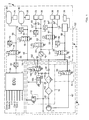
- Pressure medium lines are solid lines in the drawing, electrical lines are dashed lines.
- the drawing shows a compressed air treatment plant 2 with a compressed air supply part 4 and a consumer part 6.
- the compressed air supply part 4 comprises a compressor 7, a compressor control device 8 and an air dryer part 10.
- the consumer part 6 has a compressed air distribution line 14, a plurality of electrically directly or indirectly operable valves 16, 18, 20, 22, 24, preferably solenoid valves, with return spring and a plurality of supplied via the valves with compressed air consumer circuits 26,28, 30, 32,34, 36th , 38 on.
- a compressed air supply line 40 via a filter 42, an air dryer 44 and a check valve 46 to the manifold 14, from the leading to the solenoid valves lines 48, 50,52, 54,56 branch off.
- 24 lead compressed air lines 58, 60,62, 64, 66 to the consumer circuits.
- the line 62 branches into leading to the circles 30 and 32 lines 62 ', 62 ", wherein in the line 62" still a check valve 68 is arranged.
- a pressure limiter 70 is arranged in the supply line 52. Behind the pressure limiter 70, the line leading to the valve 22 22 branches off.
- the line 64 branches into lines 64 'and 64 "leading to the circles 34 and 36.
- Pressure sensors 72,74, 76,78, 80,82 monitor the pressure in the consumer circuits and in the distribution line 14 and give the respective pressure as a pressure signal to an electronic Control unit 84, which controls the valves directly.
- the consumer circuits 26, 28 can be, for example, service brake circuits
- the consumer circuit 30 can be a trailer brake circuit, with normally two lines leading to the trailer
- the consumer circuit 32 is a parking brake circuit with spring storage
- the consumer circuits 34 and 36 may be secondary consumption circuits, such as cab suspension, door control, etc., all that nothing has to do with the service brake circuits
- the load circuit 38 is a high pressure circuit for an air suspension system (shown as air bellows) is formed.
- An air suspension system usually requires high pressure because the air bags have a lot of volume and relatively high pressures.
- the service brake circuits 26, 28 have compressed air reservoirs 90, 92 in accordance with the guidelines 98/12 / EC.
- the compressor 7 is mechanically (pneumatically) controlled by the compressor controller 8.
- the compressor controller 8 comprises a valve 94 which can be switched by the electronic control unit 84 and which is vented in the de-energized basic state as illustrated. In this state, the compressor 7 is turned on and at least one consumer circuit is filled with compressed air. Upon reaching a set pressure threshold, the control unit 84 switches the valve 94, so that compressed air via a line 40 ', the compressed air compressor 7 turns off. If the valve 94 is de-energized for refilling due to air consumption, the valve 94 is switched back to the ground state shown in the drawing and the line 40 'is vented, so that the compressor 7 is turned on.
- the valve 94 may be a pneumatically switchable Valve be downstream, which is vented in the non-actuated basic state to relieve the compressor 7 in the actuated state.
- the air dryer section 10 comprises a valve 100 (with a small nominal diameter), whose inlet 102 is connected to the distribution line 14 and via whose output 104 a shut-off valve 106 is pneumatically connected, which is connected to the supply line 40 of the compressor 7 and serves to relieve the compressor ,
- valve 100 When the valve 100 is turned on, the compressor 7 no longer conveys into the consumer circuits, but via the valve 106 to the outside. At the same time dry air flows from the manifold 14 (from the containers 90,92 of the service brake circuits) via the valve 100 via a throttle 108 and a check valve 110 through the air dryer 44 for the regeneration of its desiccant and further through the filter 42 and the valve 106 to the outside ,
- the reference numeral 112 denotes a pressure relief valve.
- the valves 16 to 24 are controlled directly by the control unit 84, wherein the valves 16 to 22 of the load circuits 26 to 34 are open in the de-energized state, while the valve 24 of the high-pressure air-suspension circuit 38 is closed in the de-energized ground state.
- the pressure in the circuits is directly monitored by the pressure sensors 72 to 80.
- the air suspension circuit 38 is electronically controlled (also known as ECAS) by a controller 120 which is connected to the electronic control unit 84 via a data line 122.
- the control device 120 connected to the electronic control unit 84 via the data line 122 sends a compressed air request signal via the data line to the electronic control unit 84 when compressed air is required, for example as a result of leakage.
- the air suspension circuit 38 is then filled from the compressed air tanks 90, 92 of the brake circuits 26, 28 via the open valves 16, 18. If the pressure in the brake circuits drops below the prescribed value, this is communicated to the electronic control unit 84 by the brake circuit.
- the control unit 84 then closes the valve 24 and turns on the compressor 7 via the compressor controller 8.
- the compressor feeds into the brake circuits.
- the electronic control device 84 switches the valve 24 of the air-suspension circuit 38 back into the open position, so that the air-suspension circuit continues to be filled via the brake circuits or their compressed-air reservoirs 90, 92. This cyclic filling by the brake circuits is continued until the Soltik reached in the air suspension circuit 38. Then the valve 24 is closed again.
- the compressor usually promotes only in the brake circuits 26, 28. He can also - if necessary - promote the air suspension circuit, what then preferably the valves 16, 18 of the brake circuits are closed.
- the valves 20 and 22 of the secondary consumer circuits may remain open because the pressure in the associated consumer circuits 30-36 is limited by the pressure limiter 70.
- the Luftfedernik 38 has, as already mentioned above, usually a higher pressure level than the other circles; but he needs relatively little pressure and is therefore closed according to the invention without current. He also does not need within a very short time (msec or fractions of seconds) if necessary, his compressed air, so that one can take some dead time in the communication with the electronic control unit 84; the air spring circuit is therefore normally closed.
- the circuits 30 to 36 are supplied from the containers 90 and 92 of the service brake circuits 26 and 28, so that during normal driving their valves 16, 18, 20, and 22 are normally open.
- the electronic control device 84 switches the valve 16 or 18 upstream of the failed brake circuit into the blocking state and at the same time the lower pressure threshold of the normal pressure band of the intact brake circuit to a higher value, so that this brake circuit is filled to a higher pressure level.
- a higher braking energy is provided for the intact brake circuit, which increases the safety of the vehicle.
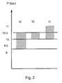
- Another increase The braking energy can be achieved if, in addition, the upper pressure threshold is also increased, cf. Fig.
- a) the normal pressure belt with a lower threshold of 9 bar and an upper threshold of 10.5 bar - without failure of a brake circuit b) the pressure band set according to the invention with, for example, 10 bar raised lower threshold and maintained upper threshold of 10.5 bar - in case of failure of a brake circuit and c) a pressure band set according to the invention with, for example, to 10 bar raised lower threshold and in addition, for example, to 11 bar raised upper threshold - in case of failure of a brake circuit.
Abstract
Description
Die Erfindung betrifft eine elektronische Luftaufbereitungsanlage für mit einer Luftfederungsanlage ausgerüstete Fahrzeuge gemäß Oberbegriff des Anspruchs 1.The invention relates to an electronic air treatment system for equipped with an air suspension system vehicles according to the preamble of
Durch die
Durch die
Durch die
Die Aufgabe der vorliegenden Erfindung besteht darin, eine Luftaufbereitungsanlage der eingangs genannten Art so auszubilden, dass nach Ausfall eines Bremskreises für den intakten Bremskreis ein möglichst hohes Druckniveau bereitgestellt wird.The object of the present invention is to provide an air treatment plant of the type mentioned in such a way that after failure of a brake circuit for the intact brake circuit the highest possible pressure level is provided.
Diese Aufgabe wird durch die Erfindung gemäß Anspruch 1 gelöst.This object is achieved by the invention according to
Vorteilhafte und zweckmäßige Ausgestaltungen der erfindungsgemäßen Aufgabenlösung sind in den Unteransprüchen angegeben.Advantageous and expedient embodiments of the task solution according to the invention are specified in the subclaims.
Die Erfindung sieht direkt oder indirekt gesteuerte Ventile, insbesondere Magnetventile, für die einzelnen Verbraucherkreise vor und schlägt vor, bei Ausfall eines Bremskreis diesen Bremskreis mittels eines zugeordneten Ventils, vorzugsweise Magnetventils, zu sperren und den intakten Bremskreis auf ein höheres Druckniveau zu befüllen, wodurch sich der minimale Bremskreisdruck entsprechend erhöht und das Druckband erst bei einem höheren Druck beginnt. Durch die erfindungsgemäß ausgebildete Luftaufbereitungsanlage ergibt sich eine Erhöhung der Fahrzeugsicherheit, weil bei Ausfall eines Bremskreises die maximal mögliche Bremsenergie für den verbleibenden intakten Bremskreis bereitgestellt wird. Die erfindungsgemäße Ausbildung lässt eine Reduzierung der Bremszylindergröße zu.The invention provides directly or indirectly controlled valves, in particular solenoid valves, for the individual consumer circuits and proposes, in case of failure of a brake circuit to block this brake circuit by means of an associated valve, preferably solenoid valve, and to fill the intact brake circuit to a higher pressure level, thereby the minimum brake circuit pressure increases accordingly and the pressure belt starts only at a higher pressure. The inventively designed air conditioning system results in an increase in vehicle safety, because in case of failure of a brake circuit, the maximum possible braking energy for the remaining intact brake circuit is provided. The inventive construction allows for a reduction of the brake cylinder size.
Die Erfindung soll nachfolgend anhand der beigefügten Zeichnung, die ein Ausführungsbeispiel einer erfindungsgemäßen Luftaufbereitungsanlage zeigt, näher erläutert werden.The invention will be explained in more detail with reference to the accompanying drawing, which shows an embodiment of an air treatment plant according to the invention.
- Fig.1Fig.1
- einen Prinzipschaltplan einer erfindungsgemäßen Druckluftaufbereitungsanlage unda schematic diagram of a compressed air treatment plant according to the invention and
- Fig.2Fig.2
- eine grafische Darstellung des mit der erfindungsgemäßen Druckaufbereitungsanlage erzielbaren Druckbandes im Vergleich zum normalen Druckband und im Vergleich zu einem Druckband, bei dem auch der Maximaldruck zusätzlich zum Minimaldruck erhöht ist.a graphical representation of the achievable with the printing treatment system according to the invention printing belt compared to the normal pressure belt and compared to a pressure belt, in which also the maximum pressure is increased in addition to the minimum pressure.
Druckmittelleitungen sind in der Zeichnung durchgezogene Linien, elektrische Leitungen sind gestrichelte Linien.Pressure medium lines are solid lines in the drawing, electrical lines are dashed lines.
Die Zeichnung zeigt eine Druckluftaufbereitungsanlage 2 mit einem Druckluftversorgungsteil 4 und einem Verbraucherteil 6. Der Druckluftversorgungsteil 4 umfasst einen Kompressor 7, eine Kompressor - Steuereinrichtung 8 und ein Lufttrocknerteil 10.The drawing shows a compressed air treatment plant 2 with a compressed air supply part 4 and a
Der Verbraucherteil 6 weist eine Druckluftverteilerleitung 14, mehrere elektrisch direkt oder indirekt betätigbare Ventile 16, 18, 20, 22, 24, vorzugsweise Magnetventile, mit Rückstellfeder und mehrere über die Ventile mit Druckluft versorgte Verbraucherkreise 26,28, 30, 32,34, 36,38 auf.The
Vom Kompressor 7 führt eine Druckluftversorgungsleitung 40 über ein Filter 42, einen Lufttrockner 44 und ein Rückschlagventil 46 zur Verteilerleitung 14, von der zu den Magnetventilen führende Leitungen 48, 50,52, 54,56 abzweigen. Von den Ventilen 16, 18, 20, 24 führen Druckluftleitungen 58, 60,62, 64, 66 zu den Verbraucherkreisen. Die Leitung 62 verzweigt sich in zu den Kreisen 30 und 32 führenden Leitungen 62', 62", wobei in der Leitung 62" noch ein Rückschlagventil 68 angeordnet ist. In der Versorgungsleitung 52 ist ein Druckbegrenzer 70 angeordnet. Hinter dem Druckbegrenzer 70 zweigt die zum Ventil 22 führende Leitung 54 ab. Die Leitung 64 verzweigt sich in zu den Kreisen 34 und 36 führenden Leitungen 64' und 64".From the compressor 7 leads a compressed
Drucksensoren 72,74, 76,78, 80,82 überwachen den Druck in den Verbraucherkreisen und in der Verteilerleitung 14 und geben den jeweiligen Druck als Drucksignal an eine elektronische Steuereinheit 84, die die Ventile direkt steuert.
Die Verbraucherkreise 26,28 können beispielsweise Betriebsbremskreise, der Verbraucherkreis 30 kann ein Anhängerbremskreis, wobei normalerweise zwei Leitungen zum Anhänger führen, der Verbraucherkreis 32 ein Feststellebremskreis mit Federspeicher, die Verbraucherkreise 34 und 36 können Nebenverbrauchskreise, wie Fahrerhausfederung, Türsteuerung etc., alles was nichts mit den Betriebsbremskreisen zu tun hat, und der Verbraucherkreis 38 ist ein Hochdruckkreis für eine Luftfederungsanlage ( als Luftbalg dargestellt ) ausgebildet. Eine Luftfederungsanlage benötigt normalerweise Hochdruck, weil die Luftfederbälge viel Volumen und relativ hohe Drücke aufweisen.The
Die Betriebsbremskreise 26,28 weisen Druckluftbehälter 90,92 entsprechend den Richtlinien 98/12/ EG auf.The
Der Kompressor 7 wird über die Kompressorsteuerung 8 mechanisch (pneumatisch) gesteuert. Die Kompressor - Steuerung 8 umfasst ein durch die elektronische Steuereinheit 84 schaltbares Ventil 94, das im stromlosen Grundzustand, wie dargestellt, entlüftet ist. In diesem Zustand ist der Kompressor 7 eingeschaltet und wenigstens ein Verbraucherkreis wird mit Druckluft befüllt. Bei Erreichen einer eingestellten Druckschwelle schaltet die Steuereinheit 84 das Ventil 94 um, so dass Druckluft über eine Leitung 40' den druckluftbetätigbaren Kompressor 7 ausschaltet. Wird das Ventil 94 stromlos geschaltet für ein erneutes Auffüllen infolge eines Luftverbrauchs, wird das Ventil 94 wieder in den in der Zeichnung dargestellten Grundzustand geschaltet und die Leitung 40' entlüftet, so dass der Kompressor 7 eingeschaltet wird. Alternativ zu der beschriebenen Ausführungsform kann dem Ventil 94 ein pneumatisch schaltbares Ventil nachgeschaltet sein, das im nicht betätigten Grundzustand entlüftet ist zur Entlastung des Kompressors 7 im betätigten Zustand.The compressor 7 is mechanically (pneumatically) controlled by the compressor controller 8. The compressor controller 8 comprises a
Der Lufttrocknerteil 10 umfasst ein Ventil 100 (mit kleiner Nennweite), dessen Eingang 102 mit der Verteilerleitung 14 verbunden ist und über dessen Ausgang 104 ein Abschaltventil 106 pneumatisch geschaltet wird, das mit der Versorgungsleitung 40 des Kompressors 7 verbunden ist und zur Entlastung des Kompressors dient.The
Wenn das Ventil 100 durchgeschaltet ist, fördert der Kompressor 7 nicht mehr in die Verbraucherkreise, sondern über das Ventil 106 ins Freie. Gleichzeitig strömt trockene Luft aus der Verteilerleitung 14 (aus den Behältern 90,92 der Betriebsbremskreise) über das Ventil 100 über eine Drossel 108 und ein Rückschlagventil 110 durch den Lufttrockner 44 zur Regeneration seines Trockenmittels und weiter über den Filter 42 und das Ventil 106 ins Freie.When the
Das Bezugszeichen 112 bezeichnet ein Überdruckventil.The
Die Ventile 16 bis 24 werden direkt von der Steuereinheit 84 gesteuert, wobei die Ventile 16 bis 22 der Verbraucherkreise 26 bis 34 im stromlosen Zustand offen sind, während das Ventil 24 des Hochdruck-Luftfederungskreises 38 im stromlosen Grundzustand geschlossen ist. Der Druck in den Kreisen wird unmittelbar überwacht durch die Drucksensoren 72 bis 80. Der Luftfederungskreis 38 wird durch eine Steuereinrichtung 120 elektronisch gesteuert ( auch als ECAS bekannt ), die über eine Datenleitung 122 mit der elektronischen Steuereinheit 84 verbunden ist.The
Sollte in einem Verbraucherkreis, beispielsweise im Kreis 30 (Feststellbremskreis) der Druck absinken, erfolgt die Druckluftversorgung durch die Betriebsbremskreise über die offenen Ventile mit, wobei der Druck in den Nebenverbraucherkreisen 30 bis 36 durch den Druckbegrenzer 70 auf ein niedrigeres Niveau, beispielsweise 8,5 bar, als das Druckniveau, beispielsweise 10,5 bar, der Betriebsbremskreise 26 und 28 eingestellt wird. Der Luftfederungskreis 38 ist durch das Ventil 24 abgesperrt und steht somit nicht mit den übrigen Kreisen in Verbindung. Er weist häufig ein höheres Druckniveau, beispielsweise 10,5 bar auf.Should the pressure drop in a consumer circuit, for example in circuit 30 (parking brake circuit), this takes place the compressed air supply through the service brake circuits via the open valves with the pressure in the
Die über die Datenleitung 122 mit der elektronischen Steuereinheit 84 verbundene Steuereinrichtung 120 schickt bei Druckluftbedarf, beispielsweise infolge einer Leckage ein Druckluft-Anforderungssignal über die Datenleitung an die elektronische Steuereinheit 84. Diese prüft, ob die Drücke in den Bremskreisen 26 und 28 den vorgeschriebenen Sollwerten entsprechen. Ist dies der Fall, schaltet die Steuereinheit 84 das Ventil 24 aus der geschlossenen Grundstellung in die offene Stellung, wodurch eine Verbindung über die normal offenen Ventile 16, 18 mit den Behältern 90, 92 der Betriebsbremskreise hergestellt wird. Der Luftfederungskreis 38 wird dann aus den Druckluftbehältern 90, 92 der Bremskreise 26, 28 über deren offene Ventile 16, 18 befüllt. Sinkt der Druck in den Bremskreisen unter den vorgeschriebenen Wert, wird dies der elektronischen Steuereinheit 84 vom Bremskreis mitgeteilt. Die Steuereinheit 84 schließt daraufhin das Ventil 24 und schaltet den Kompressor 7 über die Kompressor-Steuereinrichtung 8 ein. Der Kompressor fördert in die Bremskreise. Wenn deren Solldruck wieder erreicht ist, schaltet die elektronische Steuereinrichtung 84 das Ventil 24 des Luftfederungskreises 38 wieder in die Offenstellung, so dass der Luftfederungskreis weiter über die Bremskreise bzw. deren Druckluftbehälter 90, 92 aufgefüllt wird. Dieses zyklische Auffüllen durch die Bremskreise wird solange fortgesetzt, bis der Soldruck im Luftfederungskreis 38 erreicht ist. Dann wird das Ventil 24 wieder geschlossen.The
Der Kompressor fördert normalerweise nur in die Bremskreise 26, 28. Er kann auch - falls erforderlich - in den Luftfederungskreis fördern, wozu dann vorzugsweise die Ventile 16, 18 der Bremskreise geschlossen werden. Die Ventile 20 und 22 der Nebenverbraucherkreise können offen bleiben, da der Druck in den zugeordneten Verbraucherkreisen 30 -36 durch den Druckbegrenzer 70 begrenzt wird.The compressor usually promotes only in the
Der Luftfederkreis 38 hat, wie oben schon erwähnt, in der Regel ein höheres Druckniveau als die anderen Kreise; er braucht aber relativ selten Druck und ist daher erfindungsgemäß stromlos geschlossen. Er benötigt auch nicht innerhalb sehr kurzer Zeit (msec oder Bruchteilen von Sekunden) bei Bedarf seine Druckluft, so dass man eine gewisse Totzeit in Kauf nehmen kann für die Kommunikation mit der elektronischen Steuereinheit 84 ; der Luftfederkreis ist daher normal geschlossen. Die Kreise 30 bis 36 werden aus den Behältern 90 und 92 der Betriebsbremskreise 26 und 28 versorgt, so dass während der normalen Fahrt deren Ventile 16, 18, 20, und 22 stromlos offen sind.The
Fällt der Druck in einem der Bremskreise 26, 28 unter den vorgeschriebenen minimalen Wert infolge Ausfalls dieses Bremskreises, erkennt dies die elektronische Steuereinrichtung 84, die daraufhin das dem ausgefallenen Bremskreis vorgeschaltete Ventil 16 oder 18 in den Sperrzustand schaltet und gleichzeitig den unteren Druckschwellwert des normalen Druckbandes des intakten Bremskreises auf einen höheren Wert legt, so dass dieser Bremskreis auf ein höheres Druckniveau aufgefüllt wird. Hierdurch wird eine höhere Bremsenergie für den intakten Bremskreis bereitgestellt, was die Sicherheit des Fahrzeugs erhöht. Eine weitere Erhöhung der Bremsenergie kann dadurch erreicht werden, wenn zusätzlich auch der obere Druckschwellwert erhöht wird, vgl.
Claims (3)
dadurch gekennzeichnet, dass die elektrische Steuereinrichtung (84) zusätzlich den oberen Schwellwert auf einen höheren Wert bezogen auf den oberen Schwellwert des normalen Druckbandes verschiebt.Electrical air treatment plant according to claim 1,
characterized in that the electrical control means (84) additionally shifts the upper threshold to a higher value relative to the upper threshold of the normal print band.
dadurch gekennzeichnet, dass die Ventile Magnetventile sind.Electrical air treatment plant according to claim 1,
characterized in that the valves are solenoid valves.
Applications Claiming Priority (1)
| Application Number | Priority Date | Filing Date | Title |
|---|---|---|---|
| DE102007050222.4A DE102007050222B4 (en) | 2007-10-20 | 2007-10-20 | Electronic air treatment system |
Publications (2)
| Publication Number | Publication Date |
|---|---|
| EP2050596A1 true EP2050596A1 (en) | 2009-04-22 |
| EP2050596B1 EP2050596B1 (en) | 2015-11-18 |
Family
ID=40139812
Family Applications (1)
| Application Number | Title | Priority Date | Filing Date |
|---|---|---|---|
| EP08014327.4A Active EP2050596B1 (en) | 2007-10-20 | 2008-08-12 | Electronic air supply device |
Country Status (2)
| Country | Link |
|---|---|
| EP (1) | EP2050596B1 (en) |
| DE (1) | DE102007050222B4 (en) |
Cited By (4)
| Publication number | Priority date | Publication date | Assignee | Title |
|---|---|---|---|---|
| EP2371644A3 (en) * | 2009-12-22 | 2014-02-26 | Haldex Brake Products GmbH | Pressurised air assembly |
| CN108189636A (en) * | 2018-01-12 | 2018-06-22 | 中国重汽集团济南动力有限公司 | A kind of medium-heavy automobile vehicle bridge secondary lifting device |
| EP4029746A1 (en) * | 2021-01-19 | 2022-07-20 | KNORR-BREMSE Systeme für Nutzfahrzeuge GmbH | Electronically controlled protection valve |
| WO2023227267A1 (en) * | 2022-05-23 | 2023-11-30 | Zf Cv Systems Global Gmbh | Compressed air generating device and method for operating same |
Families Citing this family (2)
| Publication number | Priority date | Publication date | Assignee | Title |
|---|---|---|---|---|
| DE102010024889B4 (en) | 2010-06-24 | 2014-12-11 | Wabco Gmbh | Air supply device for a vehicle with pneumatic devices |
| DE102010024893B4 (en) | 2010-06-24 | 2021-11-04 | Zf Cv Systems Hannover Gmbh | Air treatment system for a vehicle |
Citations (6)
| Publication number | Priority date | Publication date | Assignee | Title |
|---|---|---|---|---|
| US4071284A (en) * | 1974-08-07 | 1978-01-31 | Messier-Hispano | Method and apparatus for effecting double-acting braking |
| DE19515895A1 (en) | 1995-04-29 | 1996-10-31 | Bosch Gmbh Robert | Compressed air supply device for vehicle compressed air systems and method for controlling the compressed air supply device |
| WO1998047751A1 (en) | 1997-04-23 | 1998-10-29 | Wabco Automotive U.K. Limited | Vehicle braking system and method of operation thereof |
| DE10004091C2 (en) | 2000-01-31 | 2002-11-14 | Knorr Bremse Systeme | Compressed air supply device for vehicle compressed air systems |
| EP1361132A1 (en) * | 2002-05-10 | 2003-11-12 | Haldex Brake Products GmbH | Compressed air distributing device for a pneumatic installation for a car |
| WO2005014353A1 (en) * | 2003-07-28 | 2005-02-17 | Wabco Gmbh & Co. Ohg | Method and device for identifying a defect or failure of a compressed air load circuit in an electronic compressed air installation for vehicles |
Family Cites Families (2)
| Publication number | Priority date | Publication date | Assignee | Title |
|---|---|---|---|---|
| DE502004002977D1 (en) | 2003-07-28 | 2007-04-05 | Wabco Gmbh | METHOD AND DEVICE FOR DETECTING A FAILURE OF A COMPRESSED AIR CONSUMER CIRCUIT IN AN ELECTRONIC COMPRESSED AIR SYSTEM FOR VEHICLES |
| DE10357765A1 (en) | 2003-07-28 | 2005-03-10 | Wabco Gmbh & Co Ohg | A method for refilling brake circuits after a heavy compressed air consumption and apparatus for carrying out the method |
-
2007
- 2007-10-20 DE DE102007050222.4A patent/DE102007050222B4/en not_active Expired - Fee Related
-
2008
- 2008-08-12 EP EP08014327.4A patent/EP2050596B1/en active Active
Patent Citations (6)
| Publication number | Priority date | Publication date | Assignee | Title |
|---|---|---|---|---|
| US4071284A (en) * | 1974-08-07 | 1978-01-31 | Messier-Hispano | Method and apparatus for effecting double-acting braking |
| DE19515895A1 (en) | 1995-04-29 | 1996-10-31 | Bosch Gmbh Robert | Compressed air supply device for vehicle compressed air systems and method for controlling the compressed air supply device |
| WO1998047751A1 (en) | 1997-04-23 | 1998-10-29 | Wabco Automotive U.K. Limited | Vehicle braking system and method of operation thereof |
| DE10004091C2 (en) | 2000-01-31 | 2002-11-14 | Knorr Bremse Systeme | Compressed air supply device for vehicle compressed air systems |
| EP1361132A1 (en) * | 2002-05-10 | 2003-11-12 | Haldex Brake Products GmbH | Compressed air distributing device for a pneumatic installation for a car |
| WO2005014353A1 (en) * | 2003-07-28 | 2005-02-17 | Wabco Gmbh & Co. Ohg | Method and device for identifying a defect or failure of a compressed air load circuit in an electronic compressed air installation for vehicles |
Cited By (5)
| Publication number | Priority date | Publication date | Assignee | Title |
|---|---|---|---|---|
| EP2371644A3 (en) * | 2009-12-22 | 2014-02-26 | Haldex Brake Products GmbH | Pressurised air assembly |
| CN108189636A (en) * | 2018-01-12 | 2018-06-22 | 中国重汽集团济南动力有限公司 | A kind of medium-heavy automobile vehicle bridge secondary lifting device |
| CN108189636B (en) * | 2018-01-12 | 2021-01-22 | 中国重汽集团济南动力有限公司 | Secondary lifting device for axle of medium and heavy truck |
| EP4029746A1 (en) * | 2021-01-19 | 2022-07-20 | KNORR-BREMSE Systeme für Nutzfahrzeuge GmbH | Electronically controlled protection valve |
| WO2023227267A1 (en) * | 2022-05-23 | 2023-11-30 | Zf Cv Systems Global Gmbh | Compressed air generating device and method for operating same |
Also Published As
| Publication number | Publication date |
|---|---|
| EP2050596B1 (en) | 2015-11-18 |
| DE102007050222B4 (en) | 2022-02-10 |
| DE102007050222A1 (en) | 2009-04-23 |
Similar Documents
| Publication | Publication Date | Title |
|---|---|---|
| EP1651492B1 (en) | Electronic compressed air system | |
| DE102005057004B3 (en) | Compressed air preparation device for brake force adjusting system of commercial vehicle, has excited first solenoid controlled valve, with which pressure essentially remains in a line between compressor and stop valve | |
| EP2445736B1 (en) | Compressed air supply system for a compressed air consumer circuit, in particular for an air spring system | |
| EP3145769B1 (en) | Electropneumatic brake control device with automatic ventilation of the spring applied brake in the event of a power loss | |
| EP2615003B2 (en) | Parking brake module for a pressure-driven brake system of a vehicle suitable for coupling a trailer, brake system and vehicle equipped with the parking brake module and method for same | |
| DE102006048071A1 (en) | Compressed air supply system and method for parameter determination of the system | |
| EP2050596B1 (en) | Electronic air supply device | |
| DE10357762A1 (en) | Electronic compressed air system | |
| EP2836406B1 (en) | Compressed air system for the air suply of load vehicles | |
| WO2008113549A1 (en) | Compressed air supply unit for a commercial vehicle, and method for operating a compressed air supply unit | |
| EP1508488B2 (en) | Installation of compressed air production for a vehicle and method of operating the same | |
| EP1651489B1 (en) | Electronic compressed-air system | |
| EP3112231B1 (en) | Parking brake module, brake system and vehicle using same and method for operating a parking brake having such a module | |
| EP1651491B1 (en) | Apparatus for refilling brake circuits after a large consumption of compressed air and device for carrying out said method | |
| EP1651493A1 (en) | Method and device for identifying malfunctioning of a compressed air consumer circuit in an electronic compressed air system for a vehicle | |
| WO2009132895A1 (en) | Method for controlling or regulating a level control system | |
| EP2177381B1 (en) | Valve device for a pneumatic suspension assembly | |
| WO2017134160A1 (en) | Brake system for a utility vehicle | |
| EP2226205A1 (en) | Method for the regulation of tyre pressure and tyre pressure regulating system | |
| EP2371644A2 (en) | Pressurised air assembly | |
| EP1800984B1 (en) | Method for refilling brake circuits after a large consumption of compressed air | |
| EP2789512A1 (en) | Compressed air supply device for a commercial vehicle | |
| DE102018217405A1 (en) | Compressed air treatment system |
Legal Events
| Date | Code | Title | Description |
|---|---|---|---|
| PUAI | Public reference made under article 153(3) epc to a published international application that has entered the european phase |
Free format text: ORIGINAL CODE: 0009012 |
|
| AK | Designated contracting states |
Kind code of ref document: A1 Designated state(s): AT BE BG CH CY CZ DE DK EE ES FI FR GB GR HR HU IE IS IT LI LT LU LV MC MT NL NO PL PT RO SE SI SK TR |
|
| AX | Request for extension of the european patent |
Extension state: AL BA MK RS |
|
| 17P | Request for examination filed |
Effective date: 20091022 |
|
| AKX | Designation fees paid |
Designated state(s): AT BE BG CH CY CZ DE DK EE ES FI FR GB GR HR HU IE IS IT LI LT LU LV MC MT NL NO PL PT RO SE SI SK TR |
|
| GRAP | Despatch of communication of intention to grant a patent |
Free format text: ORIGINAL CODE: EPIDOSNIGR1 |
|
| INTG | Intention to grant announced |
Effective date: 20140109 |
|
| 17Q | First examination report despatched |
Effective date: 20140226 |
|
| GRAP | Despatch of communication of intention to grant a patent |
Free format text: ORIGINAL CODE: EPIDOSNIGR1 |
|
| INTG | Intention to grant announced |
Effective date: 20150622 |
|
| GRAP | Despatch of communication of intention to grant a patent |
Free format text: ORIGINAL CODE: EPIDOSNIGR1 |
|
| INTG | Intention to grant announced |
Effective date: 20150807 |
|
| GRAS | Grant fee paid |
Free format text: ORIGINAL CODE: EPIDOSNIGR3 |
|
| GRAA | (expected) grant |
Free format text: ORIGINAL CODE: 0009210 |
|
| AK | Designated contracting states |
Kind code of ref document: B1 Designated state(s): AT BE BG CH CY CZ DE DK EE ES FI FR GB GR HR HU IE IS IT LI LT LU LV MC MT NL NO PL PT RO SE SI SK TR |
|
| REG | Reference to a national code |
Ref country code: GB Ref legal event code: FG4D Free format text: NOT ENGLISH |
|
| REG | Reference to a national code |
Ref country code: CH Ref legal event code: EP |
|
| REG | Reference to a national code |
Ref country code: AT Ref legal event code: REF Ref document number: 761352 Country of ref document: AT Kind code of ref document: T Effective date: 20151215 |
|
| REG | Reference to a national code |
Ref country code: IE Ref legal event code: FG4D Free format text: LANGUAGE OF EP DOCUMENT: GERMAN |
|
| REG | Reference to a national code |
Ref country code: DE Ref legal event code: R096 Ref document number: 502008013584 Country of ref document: DE |
|
| REG | Reference to a national code |
Ref country code: SE Ref legal event code: TRGR |
|
| REG | Reference to a national code |
Ref country code: NL Ref legal event code: MP Effective date: 20160218 |
|
| REG | Reference to a national code |
Ref country code: LT Ref legal event code: MG4D |
|
| PG25 | Lapsed in a contracting state [announced via postgrant information from national office to epo] |
Ref country code: HR Free format text: LAPSE BECAUSE OF FAILURE TO SUBMIT A TRANSLATION OF THE DESCRIPTION OR TO PAY THE FEE WITHIN THE PRESCRIBED TIME-LIMIT Effective date: 20151118 Ref country code: ES Free format text: LAPSE BECAUSE OF FAILURE TO SUBMIT A TRANSLATION OF THE DESCRIPTION OR TO PAY THE FEE WITHIN THE PRESCRIBED TIME-LIMIT Effective date: 20151118 Ref country code: IT Free format text: LAPSE BECAUSE OF FAILURE TO SUBMIT A TRANSLATION OF THE DESCRIPTION OR TO PAY THE FEE WITHIN THE PRESCRIBED TIME-LIMIT Effective date: 20151118 Ref country code: NO Free format text: LAPSE BECAUSE OF FAILURE TO SUBMIT A TRANSLATION OF THE DESCRIPTION OR TO PAY THE FEE WITHIN THE PRESCRIBED TIME-LIMIT Effective date: 20160218 Ref country code: IS Free format text: LAPSE BECAUSE OF FAILURE TO SUBMIT A TRANSLATION OF THE DESCRIPTION OR TO PAY THE FEE WITHIN THE PRESCRIBED TIME-LIMIT Effective date: 20160318 Ref country code: NL Free format text: LAPSE BECAUSE OF FAILURE TO SUBMIT A TRANSLATION OF THE DESCRIPTION OR TO PAY THE FEE WITHIN THE PRESCRIBED TIME-LIMIT Effective date: 20151118 Ref country code: LT Free format text: LAPSE BECAUSE OF FAILURE TO SUBMIT A TRANSLATION OF THE DESCRIPTION OR TO PAY THE FEE WITHIN THE PRESCRIBED TIME-LIMIT Effective date: 20151118 |
|
| PG25 | Lapsed in a contracting state [announced via postgrant information from national office to epo] |
Ref country code: PT Free format text: LAPSE BECAUSE OF FAILURE TO SUBMIT A TRANSLATION OF THE DESCRIPTION OR TO PAY THE FEE WITHIN THE PRESCRIBED TIME-LIMIT Effective date: 20160318 Ref country code: GR Free format text: LAPSE BECAUSE OF FAILURE TO SUBMIT A TRANSLATION OF THE DESCRIPTION OR TO PAY THE FEE WITHIN THE PRESCRIBED TIME-LIMIT Effective date: 20160219 Ref country code: FI Free format text: LAPSE BECAUSE OF FAILURE TO SUBMIT A TRANSLATION OF THE DESCRIPTION OR TO PAY THE FEE WITHIN THE PRESCRIBED TIME-LIMIT Effective date: 20151118 Ref country code: PL Free format text: LAPSE BECAUSE OF FAILURE TO SUBMIT A TRANSLATION OF THE DESCRIPTION OR TO PAY THE FEE WITHIN THE PRESCRIBED TIME-LIMIT Effective date: 20151118 Ref country code: LV Free format text: LAPSE BECAUSE OF FAILURE TO SUBMIT A TRANSLATION OF THE DESCRIPTION OR TO PAY THE FEE WITHIN THE PRESCRIBED TIME-LIMIT Effective date: 20151118 |
|
| PG25 | Lapsed in a contracting state [announced via postgrant information from national office to epo] |
Ref country code: CZ Free format text: LAPSE BECAUSE OF FAILURE TO SUBMIT A TRANSLATION OF THE DESCRIPTION OR TO PAY THE FEE WITHIN THE PRESCRIBED TIME-LIMIT Effective date: 20151118 |
|
| REG | Reference to a national code |
Ref country code: DE Ref legal event code: R097 Ref document number: 502008013584 Country of ref document: DE |
|
| REG | Reference to a national code |
Ref country code: FR Ref legal event code: PLFP Year of fee payment: 9 |
|
| PG25 | Lapsed in a contracting state [announced via postgrant information from national office to epo] |
Ref country code: RO Free format text: LAPSE BECAUSE OF FAILURE TO SUBMIT A TRANSLATION OF THE DESCRIPTION OR TO PAY THE FEE WITHIN THE PRESCRIBED TIME-LIMIT Effective date: 20151118 Ref country code: EE Free format text: LAPSE BECAUSE OF FAILURE TO SUBMIT A TRANSLATION OF THE DESCRIPTION OR TO PAY THE FEE WITHIN THE PRESCRIBED TIME-LIMIT Effective date: 20151118 Ref country code: DK Free format text: LAPSE BECAUSE OF FAILURE TO SUBMIT A TRANSLATION OF THE DESCRIPTION OR TO PAY THE FEE WITHIN THE PRESCRIBED TIME-LIMIT Effective date: 20151118 Ref country code: SK Free format text: LAPSE BECAUSE OF FAILURE TO SUBMIT A TRANSLATION OF THE DESCRIPTION OR TO PAY THE FEE WITHIN THE PRESCRIBED TIME-LIMIT Effective date: 20151118 |
|
| PLBE | No opposition filed within time limit |
Free format text: ORIGINAL CODE: 0009261 |
|
| STAA | Information on the status of an ep patent application or granted ep patent |
Free format text: STATUS: NO OPPOSITION FILED WITHIN TIME LIMIT |
|
| 26N | No opposition filed |
Effective date: 20160819 |
|
| PG25 | Lapsed in a contracting state [announced via postgrant information from national office to epo] |
Ref country code: SI Free format text: LAPSE BECAUSE OF FAILURE TO SUBMIT A TRANSLATION OF THE DESCRIPTION OR TO PAY THE FEE WITHIN THE PRESCRIBED TIME-LIMIT Effective date: 20151118 |
|
| PG25 | Lapsed in a contracting state [announced via postgrant information from national office to epo] |
Ref country code: BE Free format text: LAPSE BECAUSE OF NON-PAYMENT OF DUE FEES Effective date: 20160831 |
|
| PG25 | Lapsed in a contracting state [announced via postgrant information from national office to epo] |
Ref country code: MC Free format text: LAPSE BECAUSE OF FAILURE TO SUBMIT A TRANSLATION OF THE DESCRIPTION OR TO PAY THE FEE WITHIN THE PRESCRIBED TIME-LIMIT Effective date: 20151118 |
|
| REG | Reference to a national code |
Ref country code: CH Ref legal event code: PL |
|
| PG25 | Lapsed in a contracting state [announced via postgrant information from national office to epo] |
Ref country code: CH Free format text: LAPSE BECAUSE OF NON-PAYMENT OF DUE FEES Effective date: 20160831 Ref country code: LI Free format text: LAPSE BECAUSE OF NON-PAYMENT OF DUE FEES Effective date: 20160831 |
|
| REG | Reference to a national code |
Ref country code: IE Ref legal event code: MM4A |
|
| PG25 | Lapsed in a contracting state [announced via postgrant information from national office to epo] |
Ref country code: IE Free format text: LAPSE BECAUSE OF NON-PAYMENT OF DUE FEES Effective date: 20160812 |
|
| REG | Reference to a national code |
Ref country code: FR Ref legal event code: PLFP Year of fee payment: 10 |
|
| PG25 | Lapsed in a contracting state [announced via postgrant information from national office to epo] |
Ref country code: LU Free format text: LAPSE BECAUSE OF NON-PAYMENT OF DUE FEES Effective date: 20160812 |
|
| REG | Reference to a national code |
Ref country code: AT Ref legal event code: MM01 Ref document number: 761352 Country of ref document: AT Kind code of ref document: T Effective date: 20160812 |
|
| PG25 | Lapsed in a contracting state [announced via postgrant information from national office to epo] |
Ref country code: AT Free format text: LAPSE BECAUSE OF NON-PAYMENT OF DUE FEES Effective date: 20160812 |
|
| REG | Reference to a national code |
Ref country code: DE Ref legal event code: R081 Ref document number: 502008013584 Country of ref document: DE Owner name: WABCO EUROPE BVBA, BE Free format text: FORMER OWNER: WABCO GMBH, 30453 HANNOVER, DE |
|
| PG25 | Lapsed in a contracting state [announced via postgrant information from national office to epo] |
Ref country code: HU Free format text: LAPSE BECAUSE OF FAILURE TO SUBMIT A TRANSLATION OF THE DESCRIPTION OR TO PAY THE FEE WITHIN THE PRESCRIBED TIME-LIMIT; INVALID AB INITIO Effective date: 20080812 Ref country code: CY Free format text: LAPSE BECAUSE OF FAILURE TO SUBMIT A TRANSLATION OF THE DESCRIPTION OR TO PAY THE FEE WITHIN THE PRESCRIBED TIME-LIMIT Effective date: 20151118 |
|
| PG25 | Lapsed in a contracting state [announced via postgrant information from national office to epo] |
Ref country code: TR Free format text: LAPSE BECAUSE OF FAILURE TO SUBMIT A TRANSLATION OF THE DESCRIPTION OR TO PAY THE FEE WITHIN THE PRESCRIBED TIME-LIMIT Effective date: 20151118 Ref country code: MT Free format text: LAPSE BECAUSE OF FAILURE TO SUBMIT A TRANSLATION OF THE DESCRIPTION OR TO PAY THE FEE WITHIN THE PRESCRIBED TIME-LIMIT Effective date: 20151118 |
|
| PG25 | Lapsed in a contracting state [announced via postgrant information from national office to epo] |
Ref country code: BG Free format text: LAPSE BECAUSE OF FAILURE TO SUBMIT A TRANSLATION OF THE DESCRIPTION OR TO PAY THE FEE WITHIN THE PRESCRIBED TIME-LIMIT Effective date: 20151118 |
|
| REG | Reference to a national code |
Ref country code: FR Ref legal event code: PLFP Year of fee payment: 11 |
|
| PGFP | Annual fee paid to national office [announced via postgrant information from national office to epo] |
Ref country code: FR Payment date: 20210823 Year of fee payment: 14 |
|
| PGFP | Annual fee paid to national office [announced via postgrant information from national office to epo] |
Ref country code: SE Payment date: 20210823 Year of fee payment: 14 Ref country code: GB Payment date: 20210824 Year of fee payment: 14 |
|
| REG | Reference to a national code |
Ref country code: SE Ref legal event code: EUG |
|
| GBPC | Gb: european patent ceased through non-payment of renewal fee |
Effective date: 20220812 |
|
| PG25 | Lapsed in a contracting state [announced via postgrant information from national office to epo] |
Ref country code: SE Free format text: LAPSE BECAUSE OF NON-PAYMENT OF DUE FEES Effective date: 20220813 |
|
| REG | Reference to a national code |
Ref country code: DE Ref legal event code: R081 Ref document number: 502008013584 Country of ref document: DE Owner name: ZF CV SYSTEMS EUROPE BV, BE Free format text: FORMER OWNER: WABCO EUROPE BVBA, BRUESSEL, BE |
|
| P01 | Opt-out of the competence of the unified patent court (upc) registered |
Effective date: 20230528 |
|
| PG25 | Lapsed in a contracting state [announced via postgrant information from national office to epo] |
Ref country code: FR Free format text: LAPSE BECAUSE OF NON-PAYMENT OF DUE FEES Effective date: 20220831 |
|
| PG25 | Lapsed in a contracting state [announced via postgrant information from national office to epo] |
Ref country code: GB Free format text: LAPSE BECAUSE OF NON-PAYMENT OF DUE FEES Effective date: 20220812 |
|
| PGFP | Annual fee paid to national office [announced via postgrant information from national office to epo] |
Ref country code: DE Payment date: 20230620 Year of fee payment: 16 |