EP2050591A1 - Anti-skid device with mounting from the outside - Google Patents
Anti-skid device with mounting from the outside Download PDFInfo
- Publication number
- EP2050591A1 EP2050591A1 EP07425649A EP07425649A EP2050591A1 EP 2050591 A1 EP2050591 A1 EP 2050591A1 EP 07425649 A EP07425649 A EP 07425649A EP 07425649 A EP07425649 A EP 07425649A EP 2050591 A1 EP2050591 A1 EP 2050591A1
- Authority
- EP
- European Patent Office
- Prior art keywords
- wheel
- hub
- skid device
- tensioning
- chain
- Prior art date
- Legal status (The legal status is an assumption and is not a legal conclusion. Google has not performed a legal analysis and makes no representation as to the accuracy of the status listed.)
- Granted
Links
- 210000002105 tongue Anatomy 0.000 claims description 9
- 238000004804 winding Methods 0.000 claims description 8
- 210000003811 finger Anatomy 0.000 description 3
- 210000003813 thumb Anatomy 0.000 description 2
- 230000006835 compression Effects 0.000 description 1
- 238000007906 compression Methods 0.000 description 1
- 230000001419 dependent effect Effects 0.000 description 1
- 238000003780 insertion Methods 0.000 description 1
- 230000037431 insertion Effects 0.000 description 1
- 239000002184 metal Substances 0.000 description 1
- 238000012986 modification Methods 0.000 description 1
- 230000004048 modification Effects 0.000 description 1
Images


Classifications
-
- B—PERFORMING OPERATIONS; TRANSPORTING
- B60—VEHICLES IN GENERAL
- B60C—VEHICLE TYRES; TYRE INFLATION; TYRE CHANGING; CONNECTING VALVES TO INFLATABLE ELASTIC BODIES IN GENERAL; DEVICES OR ARRANGEMENTS RELATED TO TYRES
- B60C27/00—Non-skid devices temporarily attachable to resilient tyres or resiliently-tyred wheels
- B60C27/06—Non-skid devices temporarily attachable to resilient tyres or resiliently-tyred wheels extending over the complete circumference of the tread, e.g. made of chains or cables
- B60C27/10—Non-skid devices temporarily attachable to resilient tyres or resiliently-tyred wheels extending over the complete circumference of the tread, e.g. made of chains or cables having tensioning means
-
- B—PERFORMING OPERATIONS; TRANSPORTING
- B60—VEHICLES IN GENERAL
- B60C—VEHICLE TYRES; TYRE INFLATION; TYRE CHANGING; CONNECTING VALVES TO INFLATABLE ELASTIC BODIES IN GENERAL; DEVICES OR ARRANGEMENTS RELATED TO TYRES
- B60C27/00—Non-skid devices temporarily attachable to resilient tyres or resiliently-tyred wheels
- B60C27/06—Non-skid devices temporarily attachable to resilient tyres or resiliently-tyred wheels extending over the complete circumference of the tread, e.g. made of chains or cables
- B60C27/061—Non-skid devices temporarily attachable to resilient tyres or resiliently-tyred wheels extending over the complete circumference of the tread, e.g. made of chains or cables provided with radial arms for supporting the ground engaging parts on the tread
-
- B—PERFORMING OPERATIONS; TRANSPORTING
- B60—VEHICLES IN GENERAL
- B60C—VEHICLE TYRES; TYRE INFLATION; TYRE CHANGING; CONNECTING VALVES TO INFLATABLE ELASTIC BODIES IN GENERAL; DEVICES OR ARRANGEMENTS RELATED TO TYRES
- B60C27/00—Non-skid devices temporarily attachable to resilient tyres or resiliently-tyred wheels
- B60C27/06—Non-skid devices temporarily attachable to resilient tyres or resiliently-tyred wheels extending over the complete circumference of the tread, e.g. made of chains or cables
- B60C27/062—Non-skid devices temporarily attachable to resilient tyres or resiliently-tyred wheels extending over the complete circumference of the tread, e.g. made of chains or cables provided with fastening means
- B60C27/063—Non-skid devices temporarily attachable to resilient tyres or resiliently-tyred wheels extending over the complete circumference of the tread, e.g. made of chains or cables provided with fastening means acting on the wheel, e.g. on the rim or wheel bolts
Definitions
- the present invention refers to an anti-skid device, commonly known as a snow chain, adapted to be mounted from the side of the wheel facing towards the outside of the vehicle.
- snow chains with mounting from the outside, which comprise a central hub from which a plurality of arms or spokes, connected to a terminal element which embraces the tyre tread, protrude radially.
- the terminal elements of the spokes are connected to portions of chain, which follow the tyre tread. In this manner the portions of chain can scratch or bite into the sleet or the ice on the road surface to exert a greater friction and to avoid slipping or skidding of the tyres.
- an adapter element For tensioning this type of snow chains, an adapter element is provided which is fixed to a wheel bolt or nut.
- a tensioning strap or chain which passes through the buckle of a tensioning/locking device consisting of a lever hinged to the hub of the snow chains, is fixed to the adapter element. The user must thus pull the tensioning strap manually in order to tension the snow chains and to adjust the strap coming out of the buckle of the tensioning device to the right length. The user subsequently operates the lever of the tensioning device to lock it on the hub, further tensioning the strap.
- Such a type of snow chain presents various drawbacks, due mainly to the fact that a certain force is required to the user to pull the tensioning strap, to adjust the length thereof and to lock the lever on the hub. In fact, with such a system it is generally not possible to obtain an adequate tensioning of the snow chains. Furthermore, it is often necessary to re-tension the strap after a few turns of the wheel.
- Object of the present invention is to overcome at least in part the drawbacks of the prior art by providing a snow chain with mounting from the outside that is practical and simple and quick to mount.
- Another object is to provide such a snow chain that is reliable and safe when the vehicle is travelling.
- Another object is to provide such a snow chain that is versatile and adapted to be fitted on different types of tyres.
- the anti-skid device with mounting from the outside comprises:
- the tensioning device is a jack-type device, which allows said strap or chain to be pulled in the tensioning direction and does not allow said strap to slip in the loosening direction when the vehicle is travelling.
- the jack-type tensioning device allows an easy tensioning of the strap with a high tensioning force and without any effort on the user's part. Furthermore, such a jack-type tensioning device ensures a high degree of safety of the snow chain, since the tensioning strap cannot slip in the loosening direction.
- the anti-skid device 1 mounted on a wheel 100 is illustrated.
- the anti-skid device 1 comprises a hub 2 designed to be disposed to coincide with the wheel hub 101.
- Arms or spokes 20 protrude radially from the hub 2 of the anti-skid device.
- four arms 20, each formed by a pair of suitably shaped metal rods, are shown.
- the ends of the arms 20 are connected to respective terminal elements 21 bent with a radius of curvature, which follows the edge of the tyre, so that the terminal elements 21 can be disposed on the tyre tread.
- Portions of chain 3 which are disposed in a ring along the tyre tread are connected to the terminal elements 21.
- two portions of chain 3 disposed substantially parallel to each other are shown in the Figure.
- the portions of chain 3 are connected to each other and held in position by transverse plates 30 which are disposed edgeways on the tyre tread, so as to improve the friction with the road surface by biting into the ice or into the snow.
- An adjustment device 4 is disposed between a pair of transverse plates 30 to adapt the portions of chain 3 to slightly different wheel diameters or even to compensate for the wear on the tyre, which leads to a reduction in the diameter of the wheel.
- the adjustment device 4 comprises a screw 40 having a shank 41 with a smaller diameter than the loop in the links of the portions of chain 3 so as to be able to be inserted therein.
- the shank 41 is slightly longer than the transverse friction plates 30.
- the head 42 of the screw has a larger diameter than the loop in the links of the chain 3.
- the end of the screw shank has a thread 43 to receive a nut 44 with a larger diameter than the loop of the links of portions of chain 3.
- a helical spring 45 which works under compression.
- the screw shank 41 is inserted into two links 3a and 3b of the portions of chain 3 and the nut 44 is screwed onto the threaded end 43 of the screw. Consequently, the ends of the spring 45 push the links 3a and 3b into abutment against the nut 44 and the head 42 of the screw, obtaining the greatest distancing between the links 3a and 3b of the two portions of chain 3. As a result, the diameter of the rings formed by the portions of chain 3 tends to shorten, always keeping the portions of chain 3 tensioned on the tyre.
- the anti-skid device 1 comprises an adapter device 5 adapted to be fixed to a bolt or nut 102 fixing the wheel 100.
- the adapter device 5 comprises a truncated conical head 50 having a seat adapted to receive the head of a wheel-fixing bolt or nut 102 ( Figure 2 ).
- a plurality of longitudinal slots 51 are formed in the truncated conical head 50 so as to define a plurality of tongues 52 adapted to bend elastically.
- the head 50 has a threaded part 50' which screws into a cylindrical tang 53, so as to be able to slide axially with respect thereto.
- a cylindrical operating element 54 whose bottom edge abuts against the tapered tongues 52 of the head 50 is mounted on the head 50.
- a square or polygonal pin 55 which engages in a square or polygonal hole 56 of a sprocket wheel 57 protrudes axially from one end of the tang 53.
- the sprocket wheel 57 is disposed between the ends of two levers 58 and 58', in the form of plates, provided with circular holes 59, which do not interfere with the square pin 55.
- a supporting arm 60 which has at its end a U-shaped seat 61, is disposed between the two levers 58 and 58'.
- a spring 62 which pushes a pawl 63 towards the teeth of the sprocket wheel 57, is disposed in the seat 61 of the supporting arm.
- the pawl 63 is substantially triangle-shaped and has a hole 64 to receive a pin 65 ( Figure 13 ), so as to be hinged to the levers 58 and 58'.
- the pawl 63 has a first end 66 and a second end 67, which can alternately protrude from the levers 58 and 58' so as to be operated by the user.
- the two ends 66 and 67 of the pawl are shaped with respective cam profiles 66' and 67' which mesh in the teeth of the sprocket wheel 57.
- the cam profile 66' meshes in the teeth of the sprocket wheel 57 and allows the rotation of the sprocket wheel only in a clockwise screwing direction (arrow A in Figure 13 ) when the lever assembly (58, 58', 60) is rotated in the screwing direction (arrow Al in Figure 13 ). In this situation a rotation of the arm 60 in the opposite direction (arrow B1) does not cause any rotation of the sprocket wheel 57.
- the cam profile 67' meshes in the teeth of the sprocket wheel 57 and allows the rotation of the sprocket wheel only in the anti-clockwise unscrewing direction (arrow B in Figure 13 ) when the lever assembly (58, 58', 60) is rotated in the unscrewing direction (arrow B1 in Figure 13 ).
- a rotation of the arm 60 in the opposite direction (arrow A1) does not cause any rotation of the sprocket wheel 57.
- the pawl 63 integral with the arm 60 acts on the sprocket wheel 57 as a jack, allowing the rotation of the sprocket wheel 57 only in one direction and not in the opposite direction, according to the position in which the pawl is disposed.
- the adapter device 5 is completed by a washer 68 which is disposed at the end of the lever 58' to be passed through by a screw 69 which engages in an axial threaded hole inside the square pin 55.
- the user To remove the adapter device 5, the user must press the end 67 of the pawl 63 and operate the arm 60 in the unscrewing direction, so as to cause the head 50 to come out of the cylindrical operating device 54, which no longer pushes on the tapered tongues 52.
- the tapered tongues 52 thus return elastically to the starting position and the head 50 can be detached from the wheel bolt.
- a tensioning strap or chain 7 is fixed to the lever assembly (58, 58', 60) of the adapter device 5. As shown in Figure 3 , the strap 7 is passed through the hub 2 of the snow chains and is connected to a tensioning device 8 constrained to the hub 2.
- the tensioning device 8 is a jack, which comprises a central winding shaft 80 on which the other end of the strap 7 is wound.
- the winding shaft 80 is formed by means of two semi-cylindrical elements 81 and 81' spaced apart from each other so as to create a gap 82 into which the end of the strap 7 can be inserted.
- the two semi-cylindrical elements 81 and 81' are inserted in respective semi-cylindrical holes 83 and 83' of two sprocket wheels 84a and 84b.
- the sprocket wheels 84a and 84b are disposed between pairs of circular flanges 111 and 131 of a supporting element 110 and of an operating lever 130, respectively.
- the two flanges 111 of the supporting element are on the inside, whereas the two flanges 131 of the operating lever are towards the outside.
- the flanges 111 and 131 have respective circular holes 112 and 132 through which pass the ends of the semi-cylindrical elements 81 and 81' of the shaft 80, which are constrained to each other by means of respective keys 85.
- the supporting element 110 is constrained to the hub 2 of the snow chains.
- the shaft 80 is supported rotatably by the flanges 111 of the supporting element.
- the flanges 131 of the operating lever are mounted rotatably on the shaft 80, so that the operating lever can be operated by the user.
- the flanges 111 of the supporting element have on their profile an abutment surface 113 and a notch 114.
- the flanges 111 continue with respective side arms 115 in the form of plates, which are connected to each other by a base plate 116.
- the base plate 116 has centrally an end portion 117, which protrudes at right angles therefrom.
- a through hole 118 is formed in the end portion 117.
- Respective holes 119 to receive a pin 120 on which the strap 7 can run are formed near the end of the arms 115.
- Respective slots 121 to receive a slide 122 are formed in the central part of the arms 115.
- the slide 122 has a central pin 123, which is inserted in the hole 118 of the end part 117 of the plate base plate 116.
- Around the pin 123 is wound a helical spring 124 which pushes the slide 122 towards the shaft 80.
- the slide 122 has two teeth 125a and 125b, which protrude laterally into the slots 121 to mesh with the teeth of the respective sprocket wheels 84a and 84b.
- the teeth of the sprocket wheels 84a and 84b are of such a shape as to allow the rotation of the sprocket wheels 84a and 84b only in the direction of the arrow F1 ( Figure 9 ) and not in the opposite direction of the arrow F2.
- the slide 122 has a shaped surface 126 adapted to receive the user's finger to push the slide 122 against the action of the spring 124, so that the teeth 125a and 125b of the slide do not mesh with the teeth of the sprocket wheels 84a and 84b.
- the flanges 131 of the operating lever have on their profile a stop seat 133 and a cam surface 139.
- the flanges 131 continue with respective side arms 135 in the form of plates, which are connected to each other by a base plate 136.
- the base plate 136 has centrally an end portion 137, which protrudes at right angles therefrom.
- a through hole 138 is formed in the end portion 137.
- Respective slots 141 to receive a slide 142 are formed in the central part of the arms 135.
- the slide 142 has a central pin 143, which is inserted into the hole 138 in the end part 137 of the base plate 136.
- a helical spring 144 which pushes the slide 142 towards the shaft 80, is wound around the pin 143.
- the slide 142 has two teeth 145a and 145b, which protrude laterally into the slots 141 to mesh with the teeth of the respective sprocket wheels 84a and 84b.
- the teeth of the sprocket wheels 84a and 84b have such a shape as to allow the operating lever 130 to be able to rotate in the direction of the arrow L1 ( Figure 9 ) without pulling the sprocket wheels 84a and 84b into rotation.
- the operating lever 130 rotates in the direction of the arrow L2 ( Figure 9 )
- the slide 142 has a shaped surface 146 adapted to receive the user's finger to push the slide 142 against the action of the spring 144, so that the teeth 145a and 145b of the slide disengage from the teeth of the sprocket wheels 84a and 84b and from the abutment surface 113 of the flanges 111 of the supporting element.
- the operating lever 130 can be rotated further, until the teeth 145a and 145b of the slide 142 mesh with the notches 144 of the flanges 111 of the supporting element, when the operating lever 130 is at about 180° from the supporting element 110.
- the tensioning device 8 is completely open and the cam surface 139 of the flanges 131 of the operating lever pushes on the teeth 125a and 125b of the slide 122, against the action of the spring 124, disengaging the teeth 125a and 125b from the sprocket wheels 84a and 84b.
- the sprocket wheels 84a and 84b are free to rotate in both directions of the arrows F1 and F2.
- the operator grips two spokes 20 of the anti-skid device 1 to mount them from the outside of the wheel, arranging the ring formed by the portions of chain 3 on the tyre tread.
- the operator subsequently grips the operating lever assembly (58, 58', 60) of the adapter device 4, arranges the head of the adapter device on a bolt 102 of the tyre, presses the end 66 of the pawl 63 ( Figure 13 ) with a thumb and operates the operating lever (58, 58', 60) so as to cause the rotation of the sprocket wheel 57 in the direction of the arrow A and thus the tightening of the wheel bolt.
- the operator grips the operating lever 130 of the tensioning device 8 and alternately operates said lever in the direction of the arrows L and L2, causing the rotation of the sprocket wheels 84a and 84b in the direction of the arrow F1 ( Figure 9 ) and thus the rotation of the winding shaft 80 in the direction of winding of the strap 7.
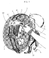
- the strap 7 winds around the shaft 80, pulling the hub 2 of the snow chains towards the hub 101 of the wheel and thus tensioning the terminal elements 21 of the arms 20 on the tyre, as shown in Figure 4 .
- the user turns the operating lever 130 so as to open the tensioning device 8. Then, with his fingers he pulls back the slide 142 against the action of the spring 144 ( Figure 8 ), so as to disengage the teeth 145a and 145b of the slide 142 from the sprocket wheels 84a and 84b and from the abutment seat 113 of the supporting element. He then continues to turn the operating lever 130 so that the teeth 145a and 145b of the slide 142 mesh with the notches 114 of the flanges 111 of the supporting element. In this situation, the cam 139 of the flanges 131 of the operating lever pushes the teeth 125a and 125b of the slide 122, so as to disengage them from the teeth of the sprocket wheels 84a and 84b.
- the sprocket wheels 84a and 84b are free and the shaft 80 can rotate in the unwinding direction of the strap 7, allowing the anti-skid device 1 to loosen and thus the hub 2 of the anti-skid device 1 to be moved away from the wheel, as shown in Figure 6 .
- the operator grips the operating lever assembly (58, 58', 60) of the adapter device 5, presses the end 67 of the pawl 63 ( Figure 13 ) with a thumb and operates the operating lever assembly (58, 58', 60) so as to cause the rotation of the sprocket wheel 57 in the direction of the arrow B and thus the loosening of the head 50 of the adapter device on the wheel bolt, so as to be able to remove the adapter device 5.
Abstract
Description
- The present invention refers to an anti-skid device, commonly known as a snow chain, adapted to be mounted from the side of the wheel facing towards the outside of the vehicle.
- Known to the art are snow chains with mounting from the outside, which comprise a central hub from which a plurality of arms or spokes, connected to a terminal element which embraces the tyre tread, protrude radially. The terminal elements of the spokes are connected to portions of chain, which follow the tyre tread. In this manner the portions of chain can scratch or bite into the sleet or the ice on the road surface to exert a greater friction and to avoid slipping or skidding of the tyres.
- For tensioning this type of snow chains, an adapter element is provided which is fixed to a wheel bolt or nut. A tensioning strap or chain, which passes through the buckle of a tensioning/locking device consisting of a lever hinged to the hub of the snow chains, is fixed to the adapter element. The user must thus pull the tensioning strap manually in order to tension the snow chains and to adjust the strap coming out of the buckle of the tensioning device to the right length. The user subsequently operates the lever of the tensioning device to lock it on the hub, further tensioning the strap.
- Such a type of snow chain presents various drawbacks, due mainly to the fact that a certain force is required to the user to pull the tensioning strap, to adjust the length thereof and to lock the lever on the hub. In fact, with such a system it is generally not possible to obtain an adequate tensioning of the snow chains. Furthermore, it is often necessary to re-tension the strap after a few turns of the wheel.
- Another drawback is represented by the adapter device. In fact the user must normally use a special key to fix the adapter by screwing to the bolt. In some cases a lever fixed to the adapter is provided to allow screwing thereof and said lever remains on the wheel during the travel, so that a force acting in the opposite direction to that of screwing of the adapter device would tend to cause a loosening thereof.
- Yet another drawback is represented by the portions of chain connected to the terminal elements of the spokes. In fact said portions of chain form a substantially rigid ring on the tyre tread, which cannot be adapted to tyres of different sizes. Furthermore, said ring of portions of chain proves unsuitable when the thickness of the tyre is reduced, due to the wear.
- Object of the present invention is to overcome at least in part the drawbacks of the prior art by providing a snow chain with mounting from the outside that is practical and simple and quick to mount.
- Another object is to provide such a snow chain that is reliable and safe when the vehicle is travelling.
- Another object is to provide such a snow chain that is versatile and adapted to be fitted on different types of tyres.
- These objects are achieved in accordance with the invention with the characteristics listed in the appended
independent claim 1. - Advantageous embodiments of the invention are apparent from the dependent claims.
- According to the invention, the anti-skid device with mounting from the outside comprises:
- a central hub designed to be disposed to coincide with the hub of the wheel on which the anti-skid device is to be mounted,
- a plurality of arms protruding radially from said hub and ending in terminal elements designed to be disposed on the tyre tread,
- portions of chain connected to said terminal elements so as to form a ring on the tyre tread,
- an adapter device adapted to be fixed to a wheel-fixing bolt or nut and carrying a tensioning strap or chain which passes through the hub of the anti-skid device to be tensioned by the user, so as to bring the hub of the anti-skid device close to the hub of the wheel, and
- a tensioning device connected to said hub of the anti-skid device, adapted to be operated by the user to tension and to lock said tensioning device.
- The tensioning device is a jack-type device, which allows said strap or chain to be pulled in the tensioning direction and does not allow said strap to slip in the loosening direction when the vehicle is travelling.
- The advantages of the snow chain according to the invention are obvious. In fact the jack-type tensioning device allows an easy tensioning of the strap with a high tensioning force and without any effort on the user's part. Furthermore, such a jack-type tensioning device ensures a high degree of safety of the snow chain, since the tensioning strap cannot slip in the loosening direction.
- Further characteristics of the invention will be made clearer by the detailed description that follows, referring to a purely exemplifying and therefore non limiting embodiment thereof, illustrated in the appended drawings, in which:
-
Figures 1 to 4 are diagrammatic perspective views, showing respectively four steps of the mounting of the snow chains according to the invention; -
Figures 5 to 7 are diagrammatic perspective views, illustrating respectively three steps of the removal of the snow chains according to the invention; -
Figure 8 is a plan view of a tensioning device for the snow chains according to the invention; -
Figure 9 is a sectional view taken along the plane of section IX-IX ofFigure 8 ; -
Figure 10 is a side view of three elements of the tensioning device ofFigure 8 ; -
Figure 11 is a top plan view of an adjustment device disposed between two portions of chain of the snow chains according to the invention; -
Figures 12 and13 are two perspective views, illustrating an adapter device for the snow chains according to the invention, exploded and assembled, respectively. - The snow chain according to the invention, designated as a whole by the
reference numeral 1, is described with the aid of the Figures. - With reference for now to
Figure 4 , theanti-skid device 1 mounted on awheel 100 is illustrated. Theanti-skid device 1 comprises ahub 2 designed to be disposed to coincide with thewheel hub 101. Arms orspokes 20 protrude radially from thehub 2 of the anti-skid device. In the Figures fourarms 20, each formed by a pair of suitably shaped metal rods, are shown. - The ends of the
arms 20 are connected to respectiveterminal elements 21 bent with a radius of curvature, which follows the edge of the tyre, so that theterminal elements 21 can be disposed on the tyre tread. Portions ofchain 3 which are disposed in a ring along the tyre tread are connected to theterminal elements 21. By way of example, two portions ofchain 3 disposed substantially parallel to each other are shown in the Figure. At suitable intervals, the portions ofchain 3 are connected to each other and held in position bytransverse plates 30 which are disposed edgeways on the tyre tread, so as to improve the friction with the road surface by biting into the ice or into the snow. - An
adjustment device 4 is disposed between a pair oftransverse plates 30 to adapt the portions ofchain 3 to slightly different wheel diameters or even to compensate for the wear on the tyre, which leads to a reduction in the diameter of the wheel. - As shown better in
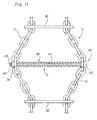
Figure 11 , theadjustment device 4 comprises ascrew 40 having ashank 41 with a smaller diameter than the loop in the links of the portions ofchain 3 so as to be able to be inserted therein. Theshank 41 is slightly longer than thetransverse friction plates 30. Thehead 42 of the screw has a larger diameter than the loop in the links of thechain 3. The end of the screw shank has athread 43 to receive anut 44 with a larger diameter than the loop of the links of portions ofchain 3. Around theshank 41, which is preferably smooth, is disposed ahelical spring 45 which works under compression. - The
screw shank 41 is inserted into twolinks chain 3 and thenut 44 is screwed onto the threadedend 43 of the screw. Consequently, the ends of thespring 45 push thelinks nut 44 and thehead 42 of the screw, obtaining the greatest distancing between thelinks chain 3. As a result, the diameter of the rings formed by the portions ofchain 3 tends to shorten, always keeping the portions ofchain 3 tensioned on the tyre. - When the tyre undergoes a reduction in diameter due to the wear, or the
anti-skid device 1 is mounted on a tyre with a slightly smaller diameter, an adjustment is made by unscrewing thenut 44 on the threadedportion 43 of thescrew 40, so as to bring the portions ofchain spring 45. In addition or as an alternative to this adjustment, anotheradjustment device 4, or a plurality ofadjustment devices 4 suitably spaced apart from each other, can be inserted in the portions ofchain 3. - Similarly, when the
anti-skid device 1 is mounted on a tyre with a slightly larger diameter, an adjustment is made by screwing thenut 44 onto the threadedpart 43 of thescrew 40, so as to bring the portions ofchain spring 45. In addition or as an alternative to said adjustment, one ormore adjustment devices 4 can be eliminated from the portions ofchain 3. - It is evident that the operations of insertion, of removal and of adjustment of the
adjustment devices 4 are extremely simple and rapid. - With reference to
Figure 2 , theanti-skid device 1 comprises anadapter device 5 adapted to be fixed to a bolt ornut 102 fixing thewheel 100. - As shown better in
Figures 12 and13 , theadapter device 5 comprises a truncatedconical head 50 having a seat adapted to receive the head of a wheel-fixing bolt or nut 102 (Figure 2 ). A plurality oflongitudinal slots 51 are formed in the truncatedconical head 50 so as to define a plurality oftongues 52 adapted to bend elastically. - The
head 50 has a threaded part 50' which screws into acylindrical tang 53, so as to be able to slide axially with respect thereto. Acylindrical operating element 54 whose bottom edge abuts against the taperedtongues 52 of thehead 50 is mounted on thehead 50. A square orpolygonal pin 55 which engages in a square orpolygonal hole 56 of asprocket wheel 57 protrudes axially from one end of thetang 53. - The
sprocket wheel 57 is disposed between the ends of twolevers 58 and 58', in the form of plates, provided withcircular holes 59, which do not interfere with thesquare pin 55. A supportingarm 60, which has at its end aU-shaped seat 61, is disposed between the twolevers 58 and 58'. Aspring 62, which pushes apawl 63 towards the teeth of thesprocket wheel 57, is disposed in theseat 61 of the supporting arm. - As shown in
Figure 12A , thepawl 63 is substantially triangle-shaped and has ahole 64 to receive a pin 65 (Figure 13 ), so as to be hinged to thelevers 58 and 58'. Thepawl 63 has afirst end 66 and asecond end 67, which can alternately protrude from thelevers 58 and 58' so as to be operated by the user. The two ends 66 and 67 of the pawl are shaped with respective cam profiles 66' and 67' which mesh in the teeth of thesprocket wheel 57. - If the user presses the
first end 66 of the pawl, the cam profile 66' meshes in the teeth of thesprocket wheel 57 and allows the rotation of the sprocket wheel only in a clockwise screwing direction (arrow A inFigure 13 ) when the lever assembly (58, 58', 60) is rotated in the screwing direction (arrow Al inFigure 13 ). In this situation a rotation of thearm 60 in the opposite direction (arrow B1) does not cause any rotation of thesprocket wheel 57. - If, on the other hand, the user presses the
second end 67 of the pawl, the cam profile 67' meshes in the teeth of thesprocket wheel 57 and allows the rotation of the sprocket wheel only in the anti-clockwise unscrewing direction (arrow B inFigure 13 ) when the lever assembly (58, 58', 60) is rotated in the unscrewing direction (arrow B1 inFigure 13 ). In this situation a rotation of thearm 60 in the opposite direction (arrow A1) does not cause any rotation of thesprocket wheel 57. - That is to say, the
pawl 63 integral with thearm 60 acts on thesprocket wheel 57 as a jack, allowing the rotation of thesprocket wheel 57 only in one direction and not in the opposite direction, according to the position in which the pawl is disposed. Theadapter device 5 is completed by awasher 68 which is disposed at the end of the lever 58' to be passed through by ascrew 69 which engages in an axial threaded hole inside thesquare pin 55. - The rotation of the
square pin 55, obtained by operating thearm 60, causes the screwing of thecylindrical tang 53 onto thehead 50 and thus the return of thehead 50 into thecylindrical operating device 54. As a result, thetongues 52 bend elastically inwards, biting the wheel bolt firmly. In this manner, the adapter device is fixed firmly to the wheel bolt. - To remove the
adapter device 5, the user must press theend 67 of thepawl 63 and operate thearm 60 in the unscrewing direction, so as to cause thehead 50 to come out of thecylindrical operating device 54, which no longer pushes on the taperedtongues 52. Thetapered tongues 52 thus return elastically to the starting position and thehead 50 can be detached from the wheel bolt. - Returning to
Figure 2 , the end of a tensioning strap orchain 7 is fixed to the lever assembly (58, 58', 60) of theadapter device 5. As shown inFigure 3 , thestrap 7 is passed through thehub 2 of the snow chains and is connected to atensioning device 8 constrained to thehub 2. - As shown better in
Figures 8 to 10 , thetensioning device 8 is a jack, which comprises a central windingshaft 80 on which the other end of thestrap 7 is wound. The windingshaft 80 is formed by means of twosemi-cylindrical elements 81 and 81' spaced apart from each other so as to create agap 82 into which the end of thestrap 7 can be inserted. - The two
semi-cylindrical elements 81 and 81' are inserted in respectivesemi-cylindrical holes 83 and 83' of twosprocket wheels sprocket wheels circular flanges element 110 and of an operatinglever 130, respectively. The twoflanges 111 of the supporting element are on the inside, whereas the twoflanges 131 of the operating lever are towards the outside. - The
flanges circular holes semi-cylindrical elements 81 and 81' of theshaft 80, which are constrained to each other by means ofrespective keys 85. The supportingelement 110 is constrained to thehub 2 of the snow chains. Theshaft 80 is supported rotatably by theflanges 111 of the supporting element. Theflanges 131 of the operating lever are mounted rotatably on theshaft 80, so that the operating lever can be operated by the user. - The
flanges 111 of the supporting element have on their profile anabutment surface 113 and anotch 114. Theflanges 111 continue withrespective side arms 115 in the form of plates, which are connected to each other by abase plate 116. Thebase plate 116 has centrally anend portion 117, which protrudes at right angles therefrom. A throughhole 118 is formed in theend portion 117. -
Respective holes 119 to receive apin 120 on which thestrap 7 can run are formed near the end of thearms 115.Respective slots 121 to receive aslide 122 are formed in the central part of thearms 115. Theslide 122 has acentral pin 123, which is inserted in thehole 118 of theend part 117 of theplate base plate 116. Around thepin 123 is wound ahelical spring 124 which pushes theslide 122 towards theshaft 80. - The
slide 122 has twoteeth 125a and 125b, which protrude laterally into theslots 121 to mesh with the teeth of therespective sprocket wheels sprocket wheels sprocket wheels Figure 9 ) and not in the opposite direction of the arrow F2. - The
slide 122 has a shapedsurface 126 adapted to receive the user's finger to push theslide 122 against the action of thespring 124, so that theteeth 125a and 125b of the slide do not mesh with the teeth of thesprocket wheels - The
flanges 131 of the operating lever have on their profile astop seat 133 and acam surface 139. Theflanges 131 continue withrespective side arms 135 in the form of plates, which are connected to each other by abase plate 136. Thebase plate 136 has centrally anend portion 137, which protrudes at right angles therefrom. A throughhole 138 is formed in theend portion 137. -
Respective slots 141 to receive aslide 142 are formed in the central part of thearms 135. Theslide 142 has acentral pin 143, which is inserted into thehole 138 in theend part 137 of thebase plate 136. Ahelical spring 144, which pushes theslide 142 towards theshaft 80, is wound around thepin 143. - The
slide 142 has twoteeth 145a and 145b, which protrude laterally into theslots 141 to mesh with the teeth of therespective sprocket wheels sprocket wheels operating lever 130 to be able to rotate in the direction of the arrow L1 (Figure 9 ) without pulling thesprocket wheels lever 130 rotates in the direction of the arrow L2 (Figure 9 ), it pulls thesprocket wheels - When the
tensioning device 8 is open (Figure 9 ), the operatinglever 130 is at about 150° from the supportingelements 110 and theteeth 145a and 145b of theslide 142 are in abutment on theabutment surface 113 of theflanges 111 of the supporting element. On the other hand, when thetensioning device 8 is closed (Figure 4 ) theoperating lever 130 is situated on the supportingelements 110 and theteeth 125a and 125b of theslide 122 are in abutment in thestop seat 133 of theflanges 131 of the operating lever. - Returning to
Figure 8 , theslide 142 has a shapedsurface 146 adapted to receive the user's finger to push theslide 142 against the action of thespring 144, so that theteeth 145a and 145b of the slide disengage from the teeth of thesprocket wheels abutment surface 113 of theflanges 111 of the supporting element. In this manner, the operatinglever 130 can be rotated further, until theteeth 145a and 145b of theslide 142 mesh with thenotches 144 of theflanges 111 of the supporting element, when the operatinglever 130 is at about 180° from the supportingelement 110. - In this situation (not shown in the Figures), the
tensioning device 8 is completely open and thecam surface 139 of theflanges 131 of the operating lever pushes on theteeth 125a and 125b of theslide 122, against the action of thespring 124, disengaging theteeth 125a and 125b from thesprocket wheels sprocket wheels - The mounting of the
anti-skid device 1 according to the invention is described hereunder with reference toFigures 1 to 4 . - With reference to
Figure 1 , the operator grips twospokes 20 of theanti-skid device 1 to mount them from the outside of the wheel, arranging the ring formed by the portions ofchain 3 on the tyre tread. - As shown in
Figure 2 , the operator subsequently grips the operating lever assembly (58, 58', 60) of theadapter device 4, arranges the head of the adapter device on abolt 102 of the tyre, presses theend 66 of the pawl 63 (Figure 13 ) with a thumb and operates the operating lever (58, 58', 60) so as to cause the rotation of thesprocket wheel 57 in the direction of the arrow A and thus the tightening of the wheel bolt. - Subsequently, as shown in
Figure 3 , the operator grips theoperating lever 130 of thetensioning device 8 and alternately operates said lever in the direction of the arrows L and L2, causing the rotation of thesprocket wheels Figure 9 ) and thus the rotation of the windingshaft 80 in the direction of winding of thestrap 7. As a result, thestrap 7 winds around theshaft 80, pulling thehub 2 of the snow chains towards thehub 101 of the wheel and thus tensioning theterminal elements 21 of thearms 20 on the tyre, as shown inFigure 4 . - It should be noted that thanks to the
tensioning device 8, of the jack type, the tensioning of these snow chains proves easy and the chains can be tensioned adequately. At the end of the tensioning, the operatinglever 130 is disposed in its closed position. In this situation, thesprocket wheels strap 7. - The removal of the
anti-skid device 1 is described hereunder with reference toFigures 5 and6 . - As shown in
Figure 5 , the user turns the operatinglever 130 so as to open thetensioning device 8. Then, with his fingers he pulls back theslide 142 against the action of the spring 144 (Figure 8 ), so as to disengage theteeth 145a and 145b of theslide 142 from thesprocket wheels abutment seat 113 of the supporting element. He then continues to turn theoperating lever 130 so that theteeth 145a and 145b of theslide 142 mesh with thenotches 114 of theflanges 111 of the supporting element. In this situation, thecam 139 of theflanges 131 of the operating lever pushes theteeth 125a and 125b of theslide 122, so as to disengage them from the teeth of thesprocket wheels - As a result, the
sprocket wheels shaft 80 can rotate in the unwinding direction of thestrap 7, allowing theanti-skid device 1 to loosen and thus thehub 2 of theanti-skid device 1 to be moved away from the wheel, as shown inFigure 6 . - Lastly, as shown in the
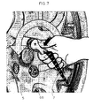
Figure 7 , the operator grips the operating lever assembly (58, 58', 60) of theadapter device 5, presses theend 67 of the pawl 63 (Figure 13 ) with a thumb and operates the operating lever assembly (58, 58', 60) so as to cause the rotation of thesprocket wheel 57 in the direction of the arrow B and thus the loosening of thehead 50 of the adapter device on the wheel bolt, so as to be able to remove theadapter device 5. - Numerous changes and modifications of detail within the reach of a person skilled in the art can be made to the present embodiment of the invention without thereby departing from the scope of the invention as set forth in the appended claims.
Claims (10)
- An anti-skid device (1) with mounting from the outside, comprising:- a central hub (2) designed to be disposed to coincide with the hub (101) of the wheel on which the anti-skid device (1) is to be mounted,- a plurality of arms (20) protruding radially from said hub (2) and ending in terminal elements (21) designed to be disposed on the tyre tread,- portions of chain (3) connected to said terminal elements (21) so as to form a ring on the tyre tread,- an adapter device (5) adapted to be fixed to a wheel-fixing bolt or nut (102), to which is secured the end of a tensioning strap or chain (7) which passes through the hub (2) of the anti-skid device to be tensioned by the user, so as to bring the hub (2) of the anti-skid device (1) close to the wheel hub (101), and- a device (8) connected to said hub (2) of the anti-skid device (1), adapted to be operated by the user to lock said tensioning strap (7),characterised in that
said device (8) is a jack-type tensioning device, which allows said strap or chain (7) to be pulled in the tensioning direction and does not allow the slipping of said strap (7) in the loosening direction. - An anti-skid device (1) according to claim 1, characterised in that said tensioning device (8) comprises:- a supporting element (110) integral with said hub (2) of the anti-skid device (1),- a winding shaft (80) supported rotatably by said supporting element (110) and on which said tensioning strap (7) is wound,- two sprocket wheels (84a, 84b) keyed onto the ends of the winding shaft (80),- an operating lever (130) mounted rotatably on said winding shaft (80) and which can be operated manually by the operator to operate said sprocket wheels (84a, 84b) in the direction of winding of the tensioning strap (7).
- An anti-skid device (1) according to claim 2, characterised in that said supporting element (110) comprises a slide (122) provided with two teeth (125a, 125b) that mesh with said sprocket wheels (84a, 84b) through the thrust of a spring (124).
- An anti-skid device (1) according to claim 2 or 3, characterised in that said operating lever (130) comprises a slide (142) provided with two teeth (145a, 145b) which mesh with said sprocket wheels (84a, 84b), through the thrust of a spring (144).
- An anti-skid device (1) according to claim 4, characterised in that said supporting element (110) comprises two flanges (111) which rotatably support said shaft (80), the profile of said flanges (111) having an abutment surface (113) and a notch (114) to receive said teeth (145a, 145b) of the slide (142) of the operating lever (130) in an open position and in a completely open position of the operating lever (130).
- An anti-skid device (1) according to any one of claims 3 to 5, characterised in that said operating lever (130) comprises two flanges (131) mounted rotatably on said shaft (80), the profile of said flanges (131) having a stop seat (133) to receive said teeth (125a, 125b) of the slide of the supporting device in a closed position of the operating lever (130) and a cam profile (139) to push said teeth (125a, 125b) of the slide (125) of the supporting device into a position of non engagement with the sprocket wheels (85a, 85b).
- An anti-skid device (1) according to any one of the preceding claims, characterised in that said adapter device (5) is a jack-type device.
- An anti-skid device (1) according to claim 7, characterised in that said adapter device (5) comprises:- a head (50) provided with tongues (52) which clamp on a wheel-fixing bolt or nut (102),- an operating cylinder (54), which causes the tightening or the loosening of said tongues (52) on the wheel-fixing bolt or nut (102),- a sprocket wheel (57), which can be operated by a jack-type lever (60) to cause a relative axial sliding between said head (50) and said operating cylinder (54),- a pawl (63), which meshes with the teeth of said sprocket wheel (57), to allow the rotation thereof, by means of a manual operation of a lever assembly (58, 58', 60) integral with said pawl (63).
- An anti-skid device (1) according to claim 8, characterised in that said pawl (63) is hinged to said lever assembly (58, 58') to pass from a first position, in which it allows the rotation of said sprocket wheel (57) only in the clamping direction of the tongues (52) of the head (50) on the wheel-fixing bolt (102), to a second position in which it allows the rotation of said sprocket wheel (57) only in the loosening direction of the tongues (52) of the head (50) on the wheel-fixing bolt (102).
- An anti-skid device (1) according to any one of the preceding claims, characterised in that it comprises an adjustment device (4) able to adapt the portions of chain (3) to slightly different wheel diameters or even to compensate for the wear on the tyre which leads to a reduction in diameter of the wheel, said adjustment device (4) comprising a screw (40) provided with a shank (41) inserted in the loops of two links (3a, 3b) of two portions of chain (3) and a spring (45) disposed around said shank (41) so as to move said links of chain (3a, 3b) apart from each other, said screw (40) having a threaded end (43) on which an adjustment nut (44) engages.
Priority Applications (6)
| Application Number | Priority Date | Filing Date | Title |
|---|---|---|---|
| EP07425649A EP2050591B1 (en) | 2007-10-15 | 2007-10-15 | Anti-skid device with mounting from the outside |
| PL07425649T PL2050591T3 (en) | 2007-10-15 | 2007-10-15 | Anti-skid device with mounting from the outside |
| AT07425649T ATE456469T1 (en) | 2007-10-15 | 2007-10-15 | ANTI-SLIP DEVICE FOR MOUNTING FROM THE OUTSIDE |
| DE602007004627T DE602007004627D1 (en) | 2007-10-15 | 2007-10-15 | Anti-slip device for mounting from the outside |
| US12/185,362 US20090095392A1 (en) | 2007-10-15 | 2008-08-04 | Anti-skid device with mounting from the outside |
| JP2008254369A JP2009096461A (en) | 2007-10-15 | 2008-09-30 | Anti-skid device with mounting from outside |
Applications Claiming Priority (1)
| Application Number | Priority Date | Filing Date | Title |
|---|---|---|---|
| EP07425649A EP2050591B1 (en) | 2007-10-15 | 2007-10-15 | Anti-skid device with mounting from the outside |
Publications (2)
| Publication Number | Publication Date |
|---|---|
| EP2050591A1 true EP2050591A1 (en) | 2009-04-22 |
| EP2050591B1 EP2050591B1 (en) | 2010-01-27 |
Family
ID=39135241
Family Applications (1)
| Application Number | Title | Priority Date | Filing Date |
|---|---|---|---|
| EP07425649A Active EP2050591B1 (en) | 2007-10-15 | 2007-10-15 | Anti-skid device with mounting from the outside |
Country Status (6)
| Country | Link |
|---|---|
| US (1) | US20090095392A1 (en) |
| EP (1) | EP2050591B1 (en) |
| JP (1) | JP2009096461A (en) |
| AT (1) | ATE456469T1 (en) |
| DE (1) | DE602007004627D1 (en) |
| PL (1) | PL2050591T3 (en) |
Cited By (4)
| Publication number | Priority date | Publication date | Assignee | Title |
|---|---|---|---|---|
| DE102010018251A1 (en) | 2010-04-23 | 2011-10-27 | Rud Ketten Rieger & Dietz Gmbh U. Co. Kg | Anti-skid device for vehicle wheels, has connection unit fixable at vehicle wheel, where traction mechanism is attached to connection unit, and clamping device is operable by hand, where clamping device acts on traction mechanism |
| EP2489529A1 (en) * | 2011-02-16 | 2012-08-22 | Thule Sweden AB | Anti slip device for a wheel and a method for mounting the anti slip device |
| EP2995479A1 (en) * | 2014-09-15 | 2016-03-16 | Joubert Productions | Anti-slip device for a motor vehicle wheel |
| IT201900007662A1 (en) | 2019-05-30 | 2020-11-30 | Koenig Spa | ANTI-SLIP DEVICE WITH EXTERNAL MOUNTING PARTICULARLY FOR WHEELS WITH ALLOY RIMS |
Families Citing this family (6)
| Publication number | Priority date | Publication date | Assignee | Title |
|---|---|---|---|---|
| US20140102609A1 (en) * | 2012-10-11 | 2014-04-17 | Walmec S.P.A. | Anti-skid device for wheels |
| US20140367014A1 (en) * | 2013-06-17 | 2014-12-18 | Xianglin LIAN | Motor vehicle anti-skid crawler |
| US11479101B2 (en) * | 2019-11-11 | 2022-10-25 | SinchTech Covers, LLC | Vehicle cover and integrated security system |
| US10967719B1 (en) | 2019-11-11 | 2021-04-06 | SinchTech Covers, LLC | Vehicle cover and integrated security system |
| WO2023278242A1 (en) * | 2021-06-28 | 2023-01-05 | SinchTech Covers, LLC | Vehicle cover and integrated security system |
| CN116533690B (en) * | 2023-07-04 | 2023-09-08 | 之江实验室 | Automatic anti-skid system for vehicle |
Citations (4)
| Publication number | Priority date | Publication date | Assignee | Title |
|---|---|---|---|---|
| DE2021168A1 (en) | 1969-05-02 | 1971-11-18 | Southwire Co | Method and device for continuous casting at high speed |
| DE20211680U1 (en) * | 2002-07-24 | 2003-12-04 | Rud-Kettenfabrik Rieger & Dietz Gmbh U. Co. | Tightening device for chain attached to wheel as slip protection, designed as flexible but not elastic strap |
| US20040163747A1 (en) | 2001-07-26 | 2004-08-26 | Helmut Kaiser | Nonskid device for the wheels of vehicles |
| EP1466762A1 (en) | 2003-04-08 | 2004-10-13 | Targa Sa | Snow chain for automotive vehicle |
Family Cites Families (6)
| Publication number | Priority date | Publication date | Assignee | Title |
|---|---|---|---|---|
| US1293901A (en) * | 1918-04-16 | 1919-02-11 | Quintues C Penington | Non-skid tire-tread. |
| US1357448A (en) * | 1918-04-24 | 1920-11-02 | Emil E Ellison | Wheel attachment |
| US3295582A (en) * | 1965-04-09 | 1967-01-03 | Hernikl Frank | Tire chain tightener |
| JPS6467406A (en) * | 1987-09-04 | 1989-03-14 | Bridgestone Corp | Fitting tool for tire antiskid device |
| JP3420600B2 (en) * | 1992-12-03 | 2003-06-23 | ブリヂストンフローテック株式会社 | Chuck structure, fastening member adapter for tire slip prevention device, and tire slip prevention device |
| AU2003246994A1 (en) * | 2002-10-29 | 2004-05-25 | Maggi Catene S.P.A. | Quick-fit anti-skid system for vehicle wheels and associated device for fixing to the wheel |
-
2007
- 2007-10-15 AT AT07425649T patent/ATE456469T1/en active
- 2007-10-15 EP EP07425649A patent/EP2050591B1/en active Active
- 2007-10-15 PL PL07425649T patent/PL2050591T3/en unknown
- 2007-10-15 DE DE602007004627T patent/DE602007004627D1/en active Active
-
2008
- 2008-08-04 US US12/185,362 patent/US20090095392A1/en not_active Abandoned
- 2008-09-30 JP JP2008254369A patent/JP2009096461A/en active Pending
Patent Citations (4)
| Publication number | Priority date | Publication date | Assignee | Title |
|---|---|---|---|---|
| DE2021168A1 (en) | 1969-05-02 | 1971-11-18 | Southwire Co | Method and device for continuous casting at high speed |
| US20040163747A1 (en) | 2001-07-26 | 2004-08-26 | Helmut Kaiser | Nonskid device for the wheels of vehicles |
| DE20211680U1 (en) * | 2002-07-24 | 2003-12-04 | Rud-Kettenfabrik Rieger & Dietz Gmbh U. Co. | Tightening device for chain attached to wheel as slip protection, designed as flexible but not elastic strap |
| EP1466762A1 (en) | 2003-04-08 | 2004-10-13 | Targa Sa | Snow chain for automotive vehicle |
Cited By (9)
| Publication number | Priority date | Publication date | Assignee | Title |
|---|---|---|---|---|
| DE102010018251A1 (en) | 2010-04-23 | 2011-10-27 | Rud Ketten Rieger & Dietz Gmbh U. Co. Kg | Anti-skid device for vehicle wheels, has connection unit fixable at vehicle wheel, where traction mechanism is attached to connection unit, and clamping device is operable by hand, where clamping device acts on traction mechanism |
| EP2489529A1 (en) * | 2011-02-16 | 2012-08-22 | Thule Sweden AB | Anti slip device for a wheel and a method for mounting the anti slip device |
| WO2012110609A1 (en) * | 2011-02-16 | 2012-08-23 | Thule Sweden Ab | Anti slip device for a wheel and a method for mounting the anti slip device |
| US8991454B2 (en) | 2011-02-16 | 2015-03-31 | Thule Sweden Ab | Anti slip device for a wheel and a method for mounting the anti slip device |
| EP2995479A1 (en) * | 2014-09-15 | 2016-03-16 | Joubert Productions | Anti-slip device for a motor vehicle wheel |
| FR3025744A1 (en) * | 2014-09-15 | 2016-03-18 | Joubert Productions | ANTI-SLIP DEVICE FOR A MOTOR VEHICLE WHEEL |
| IT201900007662A1 (en) | 2019-05-30 | 2020-11-30 | Koenig Spa | ANTI-SLIP DEVICE WITH EXTERNAL MOUNTING PARTICULARLY FOR WHEELS WITH ALLOY RIMS |
| WO2020239379A1 (en) | 2019-05-30 | 2020-12-03 | König S.P.A | Anti-skid device with external mounting to the hub of a wheel particularly for wheels with alloy rims |
| DE202020005992U1 (en) | 2019-05-30 | 2024-01-10 | König S.p.A. | Anti-slip device with external mounting, especially for wheels with light alloy rims |
Also Published As
| Publication number | Publication date |
|---|---|
| DE602007004627D1 (en) | 2010-03-18 |
| PL2050591T3 (en) | 2010-06-30 |
| ATE456469T1 (en) | 2010-02-15 |
| US20090095392A1 (en) | 2009-04-16 |
| JP2009096461A (en) | 2009-05-07 |
| EP2050591B1 (en) | 2010-01-27 |
Similar Documents
| Publication | Publication Date | Title |
|---|---|---|
| EP2050591B1 (en) | Anti-skid device with mounting from the outside | |
| JP3987978B2 (en) | Tightening lock | |
| US8152139B2 (en) | Chain load binder (Ausbinder) | |
| US10220761B2 (en) | Large heavy duty ratchet | |
| US20130025098A1 (en) | Ratchet strap tensioner | |
| EP2050590B1 (en) | Snow chains mounted from the outside, with a device for fastening to the wheel | |
| US7056073B2 (en) | Load securing device and method for using the same | |
| WO2006001714A1 (en) | A tensioning apparatus | |
| EP3736144B1 (en) | Anti-skid device with external mounting for large wheels | |
| US20160174696A1 (en) | Strap and Handle Assembly | |
| US6957647B2 (en) | Portable bow press | |
| US4675949A (en) | Axially actuated hose clamp | |
| US5524869A (en) | Overlash jig | |
| CA1060328A (en) | Anti-skid attachment for vehicle tires | |
| EP2050593B1 (en) | Anti-skid device with chain length adjustment system | |
| EP1072448B1 (en) | Self-tensioning device for snow chains | |
| EP1132221B1 (en) | Cable for anti-return device particulary for anti-skid devices | |
| JP2768868B2 (en) | Tightening device for tire slippers | |
| KR20140140575A (en) | Device for fastening an anti-skid chain | |
| FR2902725A1 (en) | Load carrier e.g. bicycle carrier, for motor vehicle, has tensioning unit connected to frame, and applying traction on tie-down strap for adjustable tensioning of strap, when strap is connected to motor vehicle | |
| GB2555427A (en) | A ratchet strap tensioner | |
| JPH0427608A (en) | Antiskid device | |
| US8397348B2 (en) | Binding strap device for securing cargo | |
| JPH04136903U (en) | Tire anti-slip chain rope tightening tool | |
| SI9700300A (en) | Wire tensioner |
Legal Events
| Date | Code | Title | Description |
|---|---|---|---|
| PUAI | Public reference made under article 153(3) epc to a published international application that has entered the european phase |
Free format text: ORIGINAL CODE: 0009012 |
|
| AK | Designated contracting states |
Kind code of ref document: A1 Designated state(s): AT BE BG CH CY CZ DE DK EE ES FI FR GB GR HU IE IS IT LI LT LU LV MC MT NL PL PT RO SE SI SK TR |
|
| AX | Request for extension of the european patent |
Extension state: AL BA HR MK RS |
|
| 17P | Request for examination filed |
Effective date: 20090518 |
|
| 17Q | First examination report despatched |
Effective date: 20090610 |
|
| GRAP | Despatch of communication of intention to grant a patent |
Free format text: ORIGINAL CODE: EPIDOSNIGR1 |
|
| GRAS | Grant fee paid |
Free format text: ORIGINAL CODE: EPIDOSNIGR3 |
|
| GRAA | (expected) grant |
Free format text: ORIGINAL CODE: 0009210 |
|
| AKX | Designation fees paid |
Designated state(s): AT BE BG CH CY CZ DE DK EE ES FI FR GB GR HU IE IS IT LI LT LU LV MC MT NL PL PT RO SE SI SK TR |
|
| AK | Designated contracting states |
Kind code of ref document: B1 Designated state(s): AT BE BG CH CY CZ DE DK EE ES FI FR GB GR HU IE IS IT LI LT LU LV MC MT NL PL PT RO SE SI SK TR |
|
| REG | Reference to a national code |
Ref country code: GB Ref legal event code: FG4D |
|
| REG | Reference to a national code |
Ref country code: CH Ref legal event code: EP |
|
| REG | Reference to a national code |
Ref country code: IE Ref legal event code: FG4D |
|
| REF | Corresponds to: |
Ref document number: 602007004627 Country of ref document: DE Date of ref document: 20100318 Kind code of ref document: P |
|
| REG | Reference to a national code |
Ref country code: NL Ref legal event code: VDEP Effective date: 20100127 |
|
| LTIE | Lt: invalidation of european patent or patent extension |
Effective date: 20100127 |
|
| PG25 | Lapsed in a contracting state [announced via postgrant information from national office to epo] |
Ref country code: NL Free format text: LAPSE BECAUSE OF FAILURE TO SUBMIT A TRANSLATION OF THE DESCRIPTION OR TO PAY THE FEE WITHIN THE PRESCRIBED TIME-LIMIT Effective date: 20100127 Ref country code: LT Free format text: LAPSE BECAUSE OF FAILURE TO SUBMIT A TRANSLATION OF THE DESCRIPTION OR TO PAY THE FEE WITHIN THE PRESCRIBED TIME-LIMIT Effective date: 20100127 Ref country code: PT Free format text: LAPSE BECAUSE OF FAILURE TO SUBMIT A TRANSLATION OF THE DESCRIPTION OR TO PAY THE FEE WITHIN THE PRESCRIBED TIME-LIMIT Effective date: 20100527 Ref country code: ES Free format text: LAPSE BECAUSE OF FAILURE TO SUBMIT A TRANSLATION OF THE DESCRIPTION OR TO PAY THE FEE WITHIN THE PRESCRIBED TIME-LIMIT Effective date: 20100508 Ref country code: IS Free format text: LAPSE BECAUSE OF FAILURE TO SUBMIT A TRANSLATION OF THE DESCRIPTION OR TO PAY THE FEE WITHIN THE PRESCRIBED TIME-LIMIT Effective date: 20100527 |
|
| PG25 | Lapsed in a contracting state [announced via postgrant information from national office to epo] |
Ref country code: LV Free format text: LAPSE BECAUSE OF FAILURE TO SUBMIT A TRANSLATION OF THE DESCRIPTION OR TO PAY THE FEE WITHIN THE PRESCRIBED TIME-LIMIT Effective date: 20100127 Ref country code: FI Free format text: LAPSE BECAUSE OF FAILURE TO SUBMIT A TRANSLATION OF THE DESCRIPTION OR TO PAY THE FEE WITHIN THE PRESCRIBED TIME-LIMIT Effective date: 20100127 Ref country code: SI Free format text: LAPSE BECAUSE OF FAILURE TO SUBMIT A TRANSLATION OF THE DESCRIPTION OR TO PAY THE FEE WITHIN THE PRESCRIBED TIME-LIMIT Effective date: 20100127 |
|
| PG25 | Lapsed in a contracting state [announced via postgrant information from national office to epo] |
Ref country code: CY Free format text: LAPSE BECAUSE OF FAILURE TO SUBMIT A TRANSLATION OF THE DESCRIPTION OR TO PAY THE FEE WITHIN THE PRESCRIBED TIME-LIMIT Effective date: 20100127 Ref country code: GR Free format text: LAPSE BECAUSE OF FAILURE TO SUBMIT A TRANSLATION OF THE DESCRIPTION OR TO PAY THE FEE WITHIN THE PRESCRIBED TIME-LIMIT Effective date: 20100428 Ref country code: RO Free format text: LAPSE BECAUSE OF FAILURE TO SUBMIT A TRANSLATION OF THE DESCRIPTION OR TO PAY THE FEE WITHIN THE PRESCRIBED TIME-LIMIT Effective date: 20100127 Ref country code: SE Free format text: LAPSE BECAUSE OF FAILURE TO SUBMIT A TRANSLATION OF THE DESCRIPTION OR TO PAY THE FEE WITHIN THE PRESCRIBED TIME-LIMIT Effective date: 20100127 Ref country code: BE Free format text: LAPSE BECAUSE OF FAILURE TO SUBMIT A TRANSLATION OF THE DESCRIPTION OR TO PAY THE FEE WITHIN THE PRESCRIBED TIME-LIMIT Effective date: 20100127 Ref country code: EE Free format text: LAPSE BECAUSE OF FAILURE TO SUBMIT A TRANSLATION OF THE DESCRIPTION OR TO PAY THE FEE WITHIN THE PRESCRIBED TIME-LIMIT Effective date: 20100127 |
|
| PG25 | Lapsed in a contracting state [announced via postgrant information from national office to epo] |
Ref country code: SK Free format text: LAPSE BECAUSE OF FAILURE TO SUBMIT A TRANSLATION OF THE DESCRIPTION OR TO PAY THE FEE WITHIN THE PRESCRIBED TIME-LIMIT Effective date: 20100127 Ref country code: CZ Free format text: LAPSE BECAUSE OF FAILURE TO SUBMIT A TRANSLATION OF THE DESCRIPTION OR TO PAY THE FEE WITHIN THE PRESCRIBED TIME-LIMIT Effective date: 20100127 Ref country code: BG Free format text: LAPSE BECAUSE OF FAILURE TO SUBMIT A TRANSLATION OF THE DESCRIPTION OR TO PAY THE FEE WITHIN THE PRESCRIBED TIME-LIMIT Effective date: 20100427 |
|
| PLBE | No opposition filed within time limit |
Free format text: ORIGINAL CODE: 0009261 |
|
| STAA | Information on the status of an ep patent application or granted ep patent |
Free format text: STATUS: NO OPPOSITION FILED WITHIN TIME LIMIT |
|
| 26N | No opposition filed |
Effective date: 20101028 |
|
| PG25 | Lapsed in a contracting state [announced via postgrant information from national office to epo] |
Ref country code: DK Free format text: LAPSE BECAUSE OF FAILURE TO SUBMIT A TRANSLATION OF THE DESCRIPTION OR TO PAY THE FEE WITHIN THE PRESCRIBED TIME-LIMIT Effective date: 20100127 |
|
| PG25 | Lapsed in a contracting state [announced via postgrant information from national office to epo] |
Ref country code: MC Free format text: LAPSE BECAUSE OF NON-PAYMENT OF DUE FEES Effective date: 20101031 |
|
| PG25 | Lapsed in a contracting state [announced via postgrant information from national office to epo] |
Ref country code: IE Free format text: LAPSE BECAUSE OF NON-PAYMENT OF DUE FEES Effective date: 20101015 |
|
| PG25 | Lapsed in a contracting state [announced via postgrant information from national office to epo] |
Ref country code: IT Free format text: LAPSE BECAUSE OF NON-PAYMENT OF DUE FEES Effective date: 20101015 Ref country code: MT Free format text: LAPSE BECAUSE OF FAILURE TO SUBMIT A TRANSLATION OF THE DESCRIPTION OR TO PAY THE FEE WITHIN THE PRESCRIBED TIME-LIMIT Effective date: 20100127 |
|
| GBPC | Gb: european patent ceased through non-payment of renewal fee |
Effective date: 20111015 |
|
| PG25 | Lapsed in a contracting state [announced via postgrant information from national office to epo] |
Ref country code: GB Free format text: LAPSE BECAUSE OF NON-PAYMENT OF DUE FEES Effective date: 20111015 |
|
| PG25 | Lapsed in a contracting state [announced via postgrant information from national office to epo] |
Ref country code: HU Free format text: LAPSE BECAUSE OF FAILURE TO SUBMIT A TRANSLATION OF THE DESCRIPTION OR TO PAY THE FEE WITHIN THE PRESCRIBED TIME-LIMIT Effective date: 20100728 Ref country code: LU Free format text: LAPSE BECAUSE OF NON-PAYMENT OF DUE FEES Effective date: 20101015 |
|
| PG25 | Lapsed in a contracting state [announced via postgrant information from national office to epo] |
Ref country code: TR Free format text: LAPSE BECAUSE OF FAILURE TO SUBMIT A TRANSLATION OF THE DESCRIPTION OR TO PAY THE FEE WITHIN THE PRESCRIBED TIME-LIMIT Effective date: 20100127 |
|
| REG | Reference to a national code |
Ref country code: FR Ref legal event code: PLFP Year of fee payment: 9 |
|
| PGFP | Annual fee paid to national office [announced via postgrant information from national office to epo] |
Ref country code: PL Payment date: 20150929 Year of fee payment: 9 |
|
| REG | Reference to a national code |
Ref country code: CH Ref legal event code: PFA Owner name: KOENIG S.P.A., IT Free format text: FORMER OWNER: THULE S.P.A., IT |
|
| REG | Reference to a national code |
Ref country code: FR Ref legal event code: PLFP Year of fee payment: 10 |
|
| PGFP | Annual fee paid to national office [announced via postgrant information from national office to epo] |
Ref country code: CH Payment date: 20161025 Year of fee payment: 10 |
|
| PGFP | Annual fee paid to national office [announced via postgrant information from national office to epo] |
Ref country code: AT Payment date: 20161025 Year of fee payment: 10 |
|
| REG | Reference to a national code |
Ref country code: FR Ref legal event code: PLFP Year of fee payment: 11 |
|
| PG25 | Lapsed in a contracting state [announced via postgrant information from national office to epo] |
Ref country code: PL Free format text: LAPSE BECAUSE OF NON-PAYMENT OF DUE FEES Effective date: 20161015 |
|
| REG | Reference to a national code |
Ref country code: CH Ref legal event code: PL |
|
| REG | Reference to a national code |
Ref country code: AT Ref legal event code: MM01 Ref document number: 456469 Country of ref document: AT Kind code of ref document: T Effective date: 20171015 |
|
| PG25 | Lapsed in a contracting state [announced via postgrant information from national office to epo] |
Ref country code: CH Free format text: LAPSE BECAUSE OF NON-PAYMENT OF DUE FEES Effective date: 20171031 Ref country code: LI Free format text: LAPSE BECAUSE OF NON-PAYMENT OF DUE FEES Effective date: 20171031 |
|
| PG25 | Lapsed in a contracting state [announced via postgrant information from national office to epo] |
Ref country code: AT Free format text: LAPSE BECAUSE OF NON-PAYMENT OF DUE FEES Effective date: 20171015 |
|
| REG | Reference to a national code |
Ref country code: FR Ref legal event code: PLFP Year of fee payment: 12 |
|
| REG | Reference to a national code |
Ref country code: DE Ref legal event code: R081 Ref document number: 602007004627 Country of ref document: DE Owner name: KONIG S.P.A., IT Free format text: FORMER OWNER: THULE S.P.A., MOLTENO, IT |
|
| PGFP | Annual fee paid to national office [announced via postgrant information from national office to epo] |
Ref country code: IT Payment date: 20230921 Year of fee payment: 17 |
|
| PGFP | Annual fee paid to national office [announced via postgrant information from national office to epo] |
Ref country code: FR Payment date: 20231023 Year of fee payment: 17 Ref country code: DE Payment date: 20231025 Year of fee payment: 17 |