EP2050419B1 - Ostomy pouch with bias members and closure means - Google Patents
Ostomy pouch with bias members and closure means Download PDFInfo
- Publication number
- EP2050419B1 EP2050419B1 EP09000527A EP09000527A EP2050419B1 EP 2050419 B1 EP2050419 B1 EP 2050419B1 EP 09000527 A EP09000527 A EP 09000527A EP 09000527 A EP09000527 A EP 09000527A EP 2050419 B1 EP2050419 B1 EP 2050419B1
- Authority
- EP
- European Patent Office
- Prior art keywords
- neck portion
- pouch
- strips
- sidewalls
- fastener
- Prior art date
- Legal status (The legal status is an assumption and is not a legal conclusion. Google has not performed a legal analysis and makes no representation as to the accuracy of the status listed.)
- Expired - Lifetime
Links
Images


Classifications
-
- A—HUMAN NECESSITIES
- A61—MEDICAL OR VETERINARY SCIENCE; HYGIENE
- A61F—FILTERS IMPLANTABLE INTO BLOOD VESSELS; PROSTHESES; DEVICES PROVIDING PATENCY TO, OR PREVENTING COLLAPSING OF, TUBULAR STRUCTURES OF THE BODY, e.g. STENTS; ORTHOPAEDIC, NURSING OR CONTRACEPTIVE DEVICES; FOMENTATION; TREATMENT OR PROTECTION OF EYES OR EARS; BANDAGES, DRESSINGS OR ABSORBENT PADS; FIRST-AID KITS
- A61F5/00—Orthopaedic methods or devices for non-surgical treatment of bones or joints; Nursing devices; Anti-rape devices
- A61F5/44—Devices worn by the patient for reception of urine, faeces, catamenial or other discharge; Portable urination aids; Colostomy devices
- A61F5/4404—Details or parts
- A61F5/4407—Closure means other than valves
Definitions
- the invention relates t a drainable ostomy pouch.
- An example of such a pouch is known from GB-A-2 346 328 .
- Drainable ostomy pouches are well known as shown, for example, in Nolan U.S. Patent 3,523,534 and Jensen et al. U.S. Patent 4,441,659 .
- Such a pouch typically has flat opposing sidewalls secured together along their edges and defining a chamber for receiving body waste material.
- One of the walls is provided with a stoma-receiving opening, and means are provided for securing the pouch to a patient's abdomen so that waste discharge from the stoma is received in the cavity.
- the drainable pouch At its lower end, has a discharge opening for draining waste material, usually provided at the end of a narrowed neck portion.
- Closure means is provided for maintaining the discharge opening in sealed condition until such time as waste material is to be drained from the pouch.
- the closure means may take the form of a clamp, as in the aforementioned Nolan patent, or some device for securing the neck portion in upwardly-rolled condition.
- conventional wire ties or wraps have also been used for that purpose.
- a drainable pouch is reusable following periodic emptying of waste material, but cleaning is necessary prior to reuse so that effective sealing can be assured and odors emanating from the resealed pouch can be avoided. Users often encounter difficulty and discomfort in unsealing, emptying, cleaning and resealing drainable pouches because of the direct exposure to waste material and because the manipulations may require greater dexterity than a patient, particularly an elderly patient, can provide. Adding to the problem is the fact that residual amounts of solid and/or liquid waste matter at the lower end of a drainage pouch tends to block or hold the walls of the pouch together, making cleaning of the inside surfaces adjacent the drain opening even more difficult.
- the invention concerns a drainable ostomy pouch according to claim 1.
- the drainable ostomy pouch of the invention has conventional sidewalls of flexible sheet material joined along their edges to define a downwardly extending neck portion terminating in a discharge opening.
- the discharge opening is closed by folding the neck portion upwardly and opened by folding the neck portion downwardly for draining the contents from the cavity.
- Each of the sidewalls of the neck portion is provided with a transversely-extending bias member in the form of a closure strip of flexible but stiff or springlike polymeric material.
- the strips located along opposite sidewalls at the discharge the opening are normally flat and disposed in straight parallel closed relation but are openable under inwardly directed finger pressure applied to opposite ends thereof. By applying inwardly directed finger pressure, the bias members or closure strips are caused to be bowed away from each other to hold the discharge opening in an open condition for draining the contents from the cavity.
- the bias members are laterally offset from one another whereas in another form of the pouch, the bias members substantially conform in size and shape and they extend continuously or uninterruptedly from one joined edge to the other. In yet another form of the drainable ostomy pouch, the bias members substantially conform in size and shape but extend less than the entire distance from one joined edge to the other, such members being centered relative to the discharge opening.
- the drainable ostomy pouch has a discharge opening that is placed in closed condition by folding the pouch in a first direction (away from the wearer's body) and is placed in an open condition by unfolding the pouch in a second, opposite direction.
- a two-part fastener is provided for selectively holding the discharge opening in the closed condition, and it includes a first part associated with the pouch generally adjacent to or near the discharge opening and a second part associated with the pouch spaced further from the discharge opening than the first part. More specifically, the second fastener part is spaced from the discharge opening to require folding the pouch until the first fastener part comes into confronting relation with the second fastener part for engagement therewith.
- the drainable ostomy pouch has a two-part fastener associated with a neck portion leading to the pouch's discharge opening.
- the fastener comprises a first fastener strip with locking means along its outer surface disposed in a first position relative to the discharge opening and a second fastener strip with interengagable locking means disposed in a second position relative to the discharge opening.
- the fastener strips each may have an array of identical mushroom-shaped locking elements along its outer surface, and the neck portion is foldable at least twice for causing the elements of the first and second fastener strips, located along opposite sides of the neck, to be brought into interlocking engagement to hold the neck portion in folded condition.
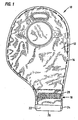
- the numeral 10 designates a drainable ostomy pouch having generally parallel sidewalls 12 and 14.
- the sidewalls 12 and 14 are joined along their edges as at 16 to define a cavity therebetween. They also define a downwardly-extending neck portion 18 which terminates in a discharge opening as at 20.
- the neck portion 18 is shown as non-symmetrical in the drawings although it will be understood that it can be symmetrical relative to the remainder of the pouch as this forms no part of the invention.
- each of the sidewalls 12 and 14 of the neck portion 18 is provided along its outer surface with a transversely-extending and generally rectangular bias member in the form of closure strips 22 and 24. The strips are located at the discharge opening 20 so as to be in generally overlapping back-to-back parallel relation.
- the bias members 22 and 24 are stiff but flexible, springlike plastic (i.e., polymeric) strips that normally are flat and disposed in straight parallel relation to maintain opening 20 in substantially closed condition. However, they can be flexed to an open condition by applying inwardly directed finger pressure to opposite ends of strips 22 and 24 to cause them to be bowed away from each other with smoothly arched curvatures as shown in Figure 3C . In this manner, the discharge opening can be opened and held in open condition for draining the contents from the cavity of pouch 10.
- the drainable ostomy pouch will also be seen to include a two-part fastener system for selectively holding the neck portion 18 in upwardly folded condition as best shown in Figure 6D .
- the two-part fastener system includes a first part 26 associated with one of the closure strips 24 on one side of the neck portion and a second part 28 at a location spaced from the discharge opening along the opposite side of the neck portion.
- the second fastener part 28 is spaced from the discharge opening at a distance sufficient to require folding the neck portion 18 upwardly at least twice (see Figures Figures 6A - 6C ). In this manner, the first fastener part 26 is brought into confronting relation with the second fastener part 28 for engagement therewith, selectively holding the neck portion 18 in its upwardly folded condition.
- first fastener part 26 is associated with an outwardly facing surface of the closure strip 24 whereas the second fastener part 28 is associated with an outwardly facing surface of the opposite wall of the neck portion 18 and substantially conforms in size and shape with closure strip 24.
- first and second fastener parts 26 and 28 are advantageously complementary materials, one being carried by closure strip 24 across one wall of the neck portion and the other by the outer surface of the other wall or the neck portion which, when interlocked together, have a retention force for maintaining the neck in folded condition absent a disengagement force sufficient to overcome the retention force.
- the sidewalls 12 and 14 are formed of a flexible plastic film that is substantially water and gas impermeable.
- One of the sidewalls 14 (the proximal or bodyside wall) is provided with a stoma-receiving opening 32 surrounded by means for attaching the drainable ostomy pouch 10 to a patient
- the attaching means may take the form of a coupling device generally designated 34 provided for detachably securing the drainable pouch 10 to an adhesive faceplate which together define a two-piece appliance.
- the pouch may be a one-piece appliance with an integral and non-separable faceplate.
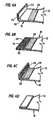
- Figures 3A and 3B illustrate bias members in the form of asymmetrical closure strips 22 and 24 which are normally flat and laterally offset from one another so as to be in straight parallel closed condition, i.e., they are adjacent one another separated only by the sidewalls 12 and 14 to which they are secured, with one end of each strip projecting laterally (in relation to neck portion 18) beyond the corresponding end of the other strip.
- the closure strip 22 and 24 can be opened under inwardly-directed finger pressure applied to opposite ends of the strips to cause them to be bowed away from each other to hold the discharge opening 20 in open condition.
- inwardly directed finger pressure against the ends 22a and 24a causes the opposite ends 22b and 24b to bear against the corresponding flat surfaces 24c and 22c of the other of the closure strips 24 and 22, respectively.
- Figures 4A and 4B illustrate bias members or closure strips 122 and 124 which are normally flat, substantially conform with each other in size and shape, and extend continuously or uninterruptedly from edge to edge so as to be in straight parallel closed condition, i.e., adjacent one another but separated only by the sidewalls 12 and 14 to which they are secured.
- the closure strips 122 and 124 can be opened under inwardly-directed finger pressure applied to opposite ends of the strips to cause them to be bowed away from each other ( Figure 4C ) and to hold the discharge opening in an open condition.
- inwardly directed finger pressure against the ends 122a, 124a and 122b, 124b of the strips causes the corresponding ends 122a, 124a and 122b, 124b to bear against one another to bow the closure strips 122 and 124 outwardly for holding the drainage opening 20 in open condition.
- the bias members 122 and 124 may need slight manipulation, or the presence of at least a small amount of waste material in the neck portion, to cause them to start being bowed away from each other as endwise squeezing force is applied.
- Figures 5A-5B illustrate bias members in the form of closure strips 222 and 224 which are normally flat, substantially conform in size and shape, and are centered, but extend less than the entire distance between the edges of the neck portion 18 so as to be in a straight parallel closed positions, i.e., adjacent each other but separated only by the sidewalls 12 and 14 to which they are secured.
- the bias members or closure strips 222 and 224 can be opened under inwardly directed finger pressure applied to opposite ends of the strips to cause them to be bowed away from each other to hold the discharge opening 20 in open position.
- inwardly-directed finger pressure against the ends 222a, 224a and 222b, 224b of the bias members 222 and 224 causes the corresponding ends 222a, 224a and 222b, 224b to bear against one another to bow the bias members outwardly for holding the drainage opening 20 in open position.
- the closure strips 222 and 224 which are centered relative to the edges may need slight manipulation or the presence of at least a small amount of waste material in the neck portion to cause them to start being bowed away from each other so as to open the discharge opening 20 as squeezing force is applied.
- Figures 3A-3C, 4A-4C, and 5A-5C illustrate three distinct, but effective, sets of bias members or closure strips for placing and holding the discharge opening of a drainable ostomy pouch 10 in open condition for draining the contents from the cavity thereof.
- the closure strips 22, 24; 122, 124; and 222, 224 are formed of any stiff but flexible polymeric material that is springlike and shape-recoverable to serve as bias members that return to straight, parallel and closed condition in the absence of inwardly-directed finger pressure such as, for example, a polyolefin such as polypropylene. Since the springiness and shape-recoverability of the strips causes them to straighten when inwardly-directed finger pressure is reduced, a user, by varying such finger pressure, may easily and selectively control the rate of discharge of waste material through the discharge opening.
- Each strip is non-porous and non-absorbent, may be secured to the sidewalls 12 and 14 (preferably to the outer surfaces of those sidewalls) or may be imbedded in such sidewalls. Because such strips are stiff, non-porous and non-absorbent, they are readily manipulated in use and are generally incapable of absorbing liquid and solid waste material.
- the two-part fastener 26 and 28 comprises a polypropylene fastener of the type sold under the trademark DUOTEC by G. Binder GmbH & Co. Holzgerlingen, Germany which is stated in product literature to work on the principle of interlocking mushroom elements.
- the discharge opening can be maintained in closed position ( Figure 6D ) absent a disengagement force sufficient to overcome the retention force which produces an auditory and tactile disengagement indication.
- Figures 19 and 20 illustrate that the interlocking first and second fastener parts 26 and 28 include spaced mushroom-shaped projections that are formed integrally with base layers 26a and 28a, respectively.
- the two interlocking components are identical, physically-distinguishable male/female components are not required. Also, because no absorbent or fabric-like material is utilized, the opposing surfaces, with their arrays of identical mushroom-shaped projections, do not absorb waste material and may be easily cleaned after a pouch-draining operation. Among the attributes for this material is its ability to provide a solid connection when pressed firmly together, its characteristic locking action that provides a user with a tactile (also audible) signal when the parts are interlocked, and its ability to be repeatedly reopened in lengthwise or crosswise directions.
- fastener parts with identical arrays of mushroom-shaped interlocking elements constitutes an important feature of a drainable ostomy pouch embodying this invention, although it is to be understood that other types of fastening means may be used which lack at least some of the attributes and advantages described above such as, for example, hook and loop fasteners as marketed under the Velcro trademark, various snaps or interlocking fasteners, or pressure-sensitive adhesive coatings that permit repeated separation and reconnection.
- the second fastener part 28 is preferably spaced from the discharge opening 20 by a distance sufficient to require folding the neck portion 18 upwardly at least twice to bring the first fastener part 26 into confronting interlocking relation with the second fastener part 28 for selectively holding the neck portion 18 in its upwardly folded condition.
- Figure 6A illustrates folding the neck portion 18 about a fold line as at 36 extending along the upper or proximal transverse edges of closure strips 22 and 24.
- Figure 6B illustrates the neck portion after completing the fold about fold line 36.
- Figure 6C illustrates a second folding of the neck portion 18 about a second transverse fold line 38 after the first fold has been completed.
- Figure 6D illustrates the neck portion 18 after the second fold has been completed to bring the first fastener part 26 into interlocking relation with second fastener part 28 for selectively holding the neck portion 18 in its upwardly folded condition.
- second fastener part 28' has a width (a dimension extending longitudinally and proximally relative to the neck portion 18) that is substantially greater than that of the first fastener part 26.
- Second fastener part 28' like first fastener part 26, is preferably rectangular in shape with a distal edge 29 located as before immediately adjacent second fold line 38 ( Figure 8 ). When the neck portion 18 for the pouch is fully folded, as shown in Figure 9 , the second fastener part 28' therefore has a proximal surface portion 29 that remains exposed.
- the exposed portion 29 constitutes a proximal and integral extension of part 28' and provides visual and tactile indications that the folding of neck portion 28 has been properly completed, with the second fold 38 located immediately adjacent distal edge 30.
- the arrangement clearly exposes the region of the first fold 36 so that a user, by sliding his/her fingers downwardly along the surface of the exposed portion or extension 29, will encounter the second fold 36 and may easily commence an unfolding operation. Such contact may be made without risk that a user might otherwise make finger contact with proximal edge 31 and attempt to unfold the neck portion 18 by applying a lifting force directly to second fastener part 28' in an effort to peel it away from pouch wall 12.
- proximal extension 29 which is securely attached to wall 12 of the neck portion, acts to distribute forces on the wall of the pouch when the neck portion has been folded and is in use, thereby reducing localized forces that might, under extreme conditions, result in tearing of the pouch wall 12.
- extension 29' does not engage fastener part 26 when the pouch neck is fully folded, the surface of the extension 29 may, if desired, be smooth and free of projections or interlockable elements.
- one of the two fastener parts may have a dimension measured in a direction across the neck portion 18 of the pouch that is substantially greater than the corresponding dimension of the fastener parts.
- the numeral 310 designates another embodiment of drainable ostomy pouch having generally parallel sidewalls 312 and 314.
- the sidewalls 312 and 314 are joined along their edges as at 316 to define a cavity therebetween. They also define a downwardly-extending neck portion 318 which terminates in a discharge opening as at 320.
- Each of the sidewalls 312 and 314 in the region of the neck portion 318 is provided with a transversely-extending bias member or closure strip such as those designated as 322 and 324 in the drawings.
- the closure strips are located at the discharge opening 320 so as to be in generally parallel back-to-back relation.
- closure strips 322 and 324 may be formed of nylon, polypropylene or any other suitable polymeric material that renders the strips stiff but flexible, non-absorbent and non-porous, and generally springlike in character. It is to be understood that closure strips 322 and 324 may be configured and function in the same manner as the described in connection with the embodiments of Figures 3A-3C . The size, shape, and composition of strips 322 and 324 may be identical to strips 22 and 24.
- First part 326 takes the form of a fastener strip having outwardly-projecting locking elements which are preferably the mushroom-shaped elements described in connection with previous embodiments.
- strips 326 and 234 are joined by an integral transversely-extending hinge 336. Perforations may be provided along the hinge line to facilitate folding of the neck portion, with the hinge 336 constituting the first fold line. It is to be understood, however, that while fastener strip 326 and closure strip 324 are shown to be connected to each other, they may instead be separate unconnected elements with the hinge line being formed solely by the line of material of sidewall 314 extending between the strips.
- the second fastener part 328 of the two-part fastener system takes the form of a transverse strip with outwardly projecting interlocking elements secured to the outer surface of sidewall 312 well above the discharge opening 320 of the pouch.
- fastener strip 328 is spaced above the discharge opening 320 a distance approximating the combined width of strips 322, 324 and 326, all three of which are of similar width.
- the embodiment of Figures 1 , 2 and 6A-6D required two folding steps to bring the interlocking elements 26 and 28 into alignment and mutual engagement
- the embodiment of Figures 10-12 requires three such folds, thereby offering even greater security for the user.
- the fastener parts or strips 326 and 328 preferably have interlocking means in the form of interfitting mushroom-shaped elements (see Figures 19 and 20 ), the user receives a tactile signal, which may even be audible, when the fastener parts are brought together and interlocked.
- the second fastener part 328 includes an integral extension 329 that extends upwardly in a direction away from opening 320.
- extension 329 is devoid of interlocking elements and presents a relatively smooth untextured surface incapable of interlocking with the projections of the first fastener part 326.
- Extension 329 otherwise functions in the same manner as described in connection with extension 29 of the embodiment depicted in Figures 7-9 .
- Figures 13-16 illustrate the three folding steps involved in securing the neck portion 318 in folded and sealed condition.
- Figure 13 depicts commencement of the first folding step with the first fold 336 occurring the line between closure strip 324 and first fastener part or strip 326.
- a second fold 338 is formed in the next folding step illustrated in Figure 14 , and a third and final fold 350 occurs as shown in Figures 15 and 16 as the interlocking elements of first fastener part or strip 326 and second fastener part or strip 328 are brought together.
- Extension 329 remains exposed above the interlocked strips to provide visual and tactile indications that the folding of the neck portion has bee properly completed.
- extension 329 performs an important function in reinforcing sidewall 312 of the neck portion and distributing forces that would otherwise be localized along a transverse line of stress directly above the upwardly-facing second fold 338.
- each of the pouches 15 formed of flexible plastic film such that the sidewalls are joined or sealed together along their edges in a conventional manner.
- each of these embodiments could be formed in another manner while enjoying the benefits of the present invention, e.g., by using a continuous tubular plastic film rather than two or more films joined together.
- the drainable ostomy pouches are provided with flexible shape-recoverable, non-porous and non-absorbent closure or stiffening strips extending transversely across each sidewall at the discharge opening at the end of the pouches' neck portions. Two or more folds are required to bring the first and second fastener parts into interlocking engagement.
- fastener parts are located along opposite sidewalls of the neck portion and have outwardly-projecting interlocking elements, ideally in the form of mushroom-shaped projections.
- the closure strips at the end of the neck portion not only facilitate opening of the discharge openings, holding such openings in open condition, and throttling and thereby controlling the rate of flow of waste material through the openings, but also define the folds as they occur and, when folding is substantially completed, help provide bulk and stiffness to the folded neck portion to assist a user in bringing the two fastener parts into interlocking engagement.
- the interlocking step is therefore the final step in a sequential folding operation with the interlocking occurring at the same time that the final fold is completed.
Abstract
Description
- The invention relates t a drainable ostomy pouch. An example of such a pouch is known from
GB-A-2 346 328 - Drainable ostomy pouches are well known as shown, for example, in
Nolan U.S. Patent 3,523,534 andJensen et al. U.S. Patent 4,441,659 . Such a pouch typically has flat opposing sidewalls secured together along their edges and defining a chamber for receiving body waste material. One of the walls is provided with a stoma-receiving opening, and means are provided for securing the pouch to a patient's abdomen so that waste discharge from the stoma is received in the cavity. At its lower end, the drainable pouch has a discharge opening for draining waste material, usually provided at the end of a narrowed neck portion. Closure means is provided for maintaining the discharge opening in sealed condition until such time as waste material is to be drained from the pouch. The closure means may take the form of a clamp, as in the aforementioned Nolan patent, or some device for securing the neck portion in upwardly-rolled condition. As will be appreciated, conventional wire ties or wraps have also been used for that purpose. - A drainable pouch is reusable following periodic emptying of waste material, but cleaning is necessary prior to reuse so that effective sealing can be assured and odors emanating from the resealed pouch can be avoided. Users often encounter difficulty and discomfort in unsealing, emptying, cleaning and resealing drainable pouches because of the direct exposure to waste material and because the manipulations may require greater dexterity than a patient, particularly an elderly patient, can provide. Adding to the problem is the fact that residual amounts of solid and/or liquid waste matter at the lower end of a drainage pouch tends to block or hold the walls of the pouch together, making cleaning of the inside surfaces adjacent the drain opening even more difficult.
- The invention concerns a drainable ostomy pouch according to claim 1.
- The drainable ostomy pouch of the invention has conventional sidewalls of flexible sheet material joined along their edges to define a downwardly extending neck portion terminating in a discharge opening. The discharge opening is closed by folding the neck portion upwardly and opened by folding the neck portion downwardly for draining the contents from the cavity. Each of the sidewalls of the neck portion is provided with a transversely-extending bias member in the form of a closure strip of flexible but stiff or springlike polymeric material. The strips located along opposite sidewalls at the discharge the opening are normally flat and disposed in straight parallel closed relation but are openable under inwardly directed finger pressure applied to opposite ends thereof. By applying inwardly directed finger pressure, the bias members or closure strips are caused to be bowed away from each other to hold the discharge opening in an open condition for draining the contents from the cavity.
- In one form of the drainable ostomy pouch, the bias members are laterally offset from one another whereas in another form of the pouch, the bias members substantially conform in size and shape and they extend continuously or uninterruptedly from one joined edge to the other. In yet another form of the drainable ostomy pouch, the bias members substantially conform in size and shape but extend less than the entire distance from one joined edge to the other, such members being centered relative to the discharge opening.
- In another respect, the drainable ostomy pouch has a discharge opening that is placed in closed condition by folding the pouch in a first direction (away from the wearer's body) and is placed in an open condition by unfolding the pouch in a second, opposite direction. A two-part fastener is provided for selectively holding the discharge opening in the closed condition, and it includes a first part associated with the pouch generally adjacent to or near the discharge opening and a second part associated with the pouch spaced further from the discharge opening than the first part. More specifically, the second fastener part is spaced from the discharge opening to require folding the pouch until the first fastener part comes into confronting relation with the second fastener part for engagement therewith.
- In yet another respect, the drainable ostomy pouch has a two-part fastener associated with a neck portion leading to the pouch's discharge opening. The fastener comprises a first fastener strip with locking means along its outer surface disposed in a first position relative to the discharge opening and a second fastener strip with interengagable locking means disposed in a second position relative to the discharge opening. Most advantageously, the fastener strips each may have an array of identical mushroom-shaped locking elements along its outer surface, and the neck portion is foldable at least twice for causing the elements of the first and second fastener strips, located along opposite sides of the neck, to be brought into interlocking engagement to hold the neck portion in folded condition.
- Other advantages and features of the invention will become apparent from the following specification when considered in view of the accompanying drawings.
-
-
Figs. 4A-4C and 5A-5C do not represent the invention as defined in claim 1. -
Figure 1 is a front elevational view of a drainable ostomy pouch having bias members in the form of laterally offset flexible closure strips. -
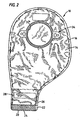
Figure 2 is a rear elevational view of the drainable ostomy pouch ofFigure 1 . -
Figure 3A is a schematic front elevational view of the neck portion of a pouch having laterally offset closure strips. -
Figure 3B is an end elevational view of the laterally offset strips ofFigure 3A in closed condition. -
Figure 3C is an end elevational view of the laterally offset strips ofFigure 3A in open condition. -
Figure 4A is a schematic front elevational view of the neck portion of a pouch having full-width closure strips. -
Figure 4B is an end elevational view of the strips ofFigure 4A in closed condition. -
Figure 4C is an end elevational view of the strips ofFigure 4A in open condition. -
Figure 5A is a schematic front elevational view of the neck portion of pouch having centered strips of a length less than the full width of the neck portion of the pouch. -
Figure 5B is an end elevational view of the centered strips ofFigure 5A in closed condition. -
Figure 5C is an end elevational view of the centered strips ofFigure 5A in open condition. -
Figures 6A-6D are schematic views illustrating the steps of securing a discharge opening of a drainable ostomy pouch in folded condition. -
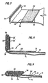
Figure 7 is a schematic perspective view of a further form of drainable ostomy pouch at the beginning of a first folding step. -
Figure 8 is a cross-sectional view of the drainable ostomy pouch ofFigure 7 at the commencement of a second folding step. -
Figure 9 is a sectional view showing the drainable ostomy pouch ofFigure 7 in fully folded condition. -
Figure 10 is a front elevational view of another form of drainable ostomy pouch in accordance with the present invention. -
Figure 11 is a rear elevational view of the drainable ostomy pouch ofFigure 10 in fully unfolded condition. -
Figure 12 is an enlarged and somewhat schematic cross-sectional view of the drainable ostomy pouch taken along the line 12-12 inFigure 11 . -
Figure 13 is a cross-sectional view similar toFigure 12 but showing the neck portion at the beginning of a folding operation. For clarity of illustration, the walls of the neck portion are shown slightly spaced apart and each is represented only by a single line. -
Figure 14 is a cross-sectional view of the neck portion of the pouch ofFigure 10 after a first fold has been made and at the start of a second fold. -
Figure 15 is a cross-sectional view of the neck portion of the pouch ofFigure 10 after a second fold has been made and at the beginning of a third fold. -
Figure 16 is a cross-sectional view of the neck portion of the pouch ofFigure 10 in fully folded condition. -
Figure 17 is a plan view of a first fastener part associated with one of the closure strips on one sidewall of the pouch adjacent to the pouches discharge opening. -
Figure 18 is a plan view of a second fastener part spaced from the discharge opening on the opposite sidewall of the pouch ofFigure 10 . -
Figure 19 is an enlarged detail view of the engagement elements provided by the first and second fastener parts on opposite sidewalls of the pouch, the engagement elements being shown in disengaged condition. -
Figure 20 is an enlarged view similar toFigure 19 but showing the engagement elements in interlocking relation. - Referring to
Figures 1 and2 of the drawings, thenumeral 10 designates a drainable ostomy pouch having generallyparallel sidewalls sidewalls neck portion 18 which terminates in a discharge opening as at 20. Theneck portion 18 is shown as non-symmetrical in the drawings although it will be understood that it can be symmetrical relative to the remainder of the pouch as this forms no part of the invention. As shown in the drawings, each of thesidewalls neck portion 18 is provided along its outer surface with a transversely-extending and generally rectangular bias member in the form of closure strips 22 and 24. The strips are located at thedischarge opening 20 so as to be in generally overlapping back-to-back parallel relation. - As will be appreciated by referring to
Figures 3A-3C , thebias members opening 20 in substantially closed condition. However, they can be flexed to an open condition by applying inwardly directed finger pressure to opposite ends ofstrips Figure 3C . In this manner, the discharge opening can be opened and held in open condition for draining the contents from the cavity ofpouch 10. - Referring once again to
Figures 1 and2 , the drainable ostomy pouch will also be seen to include a two-part fastener system for selectively holding theneck portion 18 in upwardly folded condition as best shown inFigure 6D . The two-part fastener system includes afirst part 26 associated with one of the closure strips 24 on one side of the neck portion and asecond part 28 at a location spaced from the discharge opening along the opposite side of the neck portion. Thesecond fastener part 28 is spaced from the discharge opening at a distance sufficient to require folding theneck portion 18 upwardly at least twice (see FiguresFigures 6A - 6C ). In this manner, thefirst fastener part 26 is brought into confronting relation with thesecond fastener part 28 for engagement therewith, selectively holding theneck portion 18 in its upwardly folded condition. - In the illustrated embodiment, the
first fastener part 26 is associated with an outwardly facing surface of theclosure strip 24 whereas thesecond fastener part 28 is associated with an outwardly facing surface of the opposite wall of theneck portion 18 and substantially conforms in size and shape withclosure strip 24. More specifically, the first andsecond fastener parts closure strip 24 across one wall of the neck portion and the other by the outer surface of the other wall or the neck portion which, when interlocked together, have a retention force for maintaining the neck in folded condition absent a disengagement force sufficient to overcome the retention force. - With the arrangement illustrated in
Figures 1 and2 , thesidewalls opening 32 surrounded by means for attaching thedrainable ostomy pouch 10 to a patient The attaching means may take the form of a coupling device generally designated 34 provided for detachably securing thedrainable pouch 10 to an adhesive faceplate which together define a two-piece appliance. Alternatively, the pouch may be a one-piece appliance with an integral and non-separable faceplate. -
Figures 3A and 3B illustrate bias members in the form of asymmetrical closure strips 22 and 24 which are normally flat and laterally offset from one another so as to be in straight parallel closed condition, i.e., they are adjacent one another separated only by thesidewalls closure strip discharge opening 20 in open condition. As shown inFigure 3C , inwardly directed finger pressure against theends flat surfaces 24c and 22c of the other of the closure strips 24 and 22, respectively. -
Figures 4A and 4B illustrate bias members or closure strips 122 and 124 which are normally flat, substantially conform with each other in size and shape, and extend continuously or uninterruptedly from edge to edge so as to be in straight parallel closed condition, i.e., adjacent one another but separated only by thesidewalls Figure 4C ) and to hold the discharge opening in an open condition. As shown inFigure 4C , inwardly directed finger pressure against theends drainage opening 20 in open condition. Unlike thebias members Figures 3A and 3B which are offset from one another, thebias members -
Figures 5A-5B illustrate bias members in the form of closure strips 222 and 224 which are normally flat, substantially conform in size and shape, and are centered, but extend less than the entire distance between the edges of theneck portion 18 so as to be in a straight parallel closed positions, i.e., adjacent each other but separated only by thesidewalls Figures 4A-4C , the bias members or closure strips 222 and 224 can be opened under inwardly directed finger pressure applied to opposite ends of the strips to cause them to be bowed away from each other to hold thedischarge opening 20 in open position. As shown inFigure 5C , and in essentially the same manner as inFigure 4C , inwardly-directed finger pressure against theends bias members drainage opening 20 in open position. Unlike thebias members Figures 3A and 3B which are offset from one another, the closure strips 222 and 224 which are centered relative to the edges may need slight manipulation or the presence of at least a small amount of waste material in the neck portion to cause them to start being bowed away from each other so as to open thedischarge opening 20 as squeezing force is applied. - As will be appreciated,
Figures 3A-3C, 4A-4C, and 5A-5C illustrate three distinct, but effective, sets of bias members or closure strips for placing and holding the discharge opening of adrainable ostomy pouch 10 in open condition for draining the contents from the cavity thereof. - The closure strips 22, 24; 122, 124; and 222, 224 are formed of any stiff but flexible polymeric material that is springlike and shape-recoverable to serve as bias members that return to straight, parallel and closed condition in the absence of inwardly-directed finger pressure such as, for example, a polyolefin such as polypropylene. Since the springiness and shape-recoverability of the strips causes them to straighten when inwardly-directed finger pressure is reduced, a user, by varying such finger pressure, may easily and selectively control the rate of discharge of waste material through the discharge opening. Each strip is non-porous and non-absorbent, may be secured to the
sidewalls 12 and 14 (preferably to the outer surfaces of those sidewalls) or may be imbedded in such sidewalls. Because such strips are stiff, non-porous and non-absorbent, they are readily manipulated in use and are generally incapable of absorbing liquid and solid waste material. - In a preferred embodiment, the two-
part fastener second fastener parts Figure 6D ) absent a disengagement force sufficient to overcome the retention force which produces an auditory and tactile disengagement indication.Figures 19 and 20 illustrate that the interlocking first andsecond fastener parts base layers - Also, while the material utilized in the fastener sold under the DUOTEC trademark is polypropylene, it will be understood that other polymeric materials having similar properties may be employed.
- Referring to
Figures 6A-6D , thesecond fastener part 28 is preferably spaced from thedischarge opening 20 by a distance sufficient to require folding theneck portion 18 upwardly at least twice to bring thefirst fastener part 26 into confronting interlocking relation with thesecond fastener part 28 for selectively holding theneck portion 18 in its upwardly folded condition.Figure 6A illustrates folding theneck portion 18 about a fold line as at 36 extending along the upper or proximal transverse edges of closure strips 22 and 24.Figure 6B illustrates the neck portion after completing the fold aboutfold line 36.Figure 6C illustrates a second folding of theneck portion 18 about a secondtransverse fold line 38 after the first fold has been completed.Figure 6D illustrates theneck portion 18 after the second fold has been completed to bring thefirst fastener part 26 into interlocking relation withsecond fastener part 28 for selectively holding theneck portion 18 in its upwardly folded condition. - The embodiment of
Figures 7-9 is similar to those already discussed except that second fastener part 28' has a width (a dimension extending longitudinally and proximally relative to the neck portion 18) that is substantially greater than that of thefirst fastener part 26. Second fastener part 28', likefirst fastener part 26, is preferably rectangular in shape with adistal edge 29 located as before immediately adjacent second fold line 38 (Figure 8 ). When theneck portion 18 for the pouch is fully folded, as shown inFigure 9 , the second fastener part 28' therefore has aproximal surface portion 29 that remains exposed. The exposedportion 29 constitutes a proximal and integral extension of part 28' and provides visual and tactile indications that the folding ofneck portion 28 has been properly completed, with thesecond fold 38 located immediately adjacentdistal edge 30. In addition, the arrangement clearly exposes the region of thefirst fold 36 so that a user, by sliding his/her fingers downwardly along the surface of the exposed portion orextension 29, will encounter thesecond fold 36 and may easily commence an unfolding operation. Such contact may be made without risk that a user might otherwise make finger contact withproximal edge 31 and attempt to unfold theneck portion 18 by applying a lifting force directly to second fastener part 28' in an effort to peel it away frompouch wall 12. Another important benefit of utilizing a tough polymeric material for fastener part 28' is that theproximal extension 29, which is securely attached to wall 12 of the neck portion, acts to distribute forces on the wall of the pouch when the neck portion has been folded and is in use, thereby reducing localized forces that might, under extreme conditions, result in tearing of thepouch wall 12. - Since extension 29' does not engage
fastener part 26 when the pouch neck is fully folded, the surface of theextension 29 may, if desired, be smooth and free of projections or interlockable elements. - As an alternative or addition to the embodiment of
Figures 7-9 , one of the two fastener parts may have a dimension measured in a direction across theneck portion 18 of the pouch that is substantially greater than the corresponding dimension of the fastener parts. With this arrangement, a user may easily commence an unfolding operation by gripping the ends of the strip of greater dimension and applying a force for peeling the strip away from the outer fastener part. - Referring to
Figures 10-12 of the drawings, the numeral 310 designates another embodiment of drainable ostomy pouch having generallyparallel sidewalls sidewalls neck portion 318 which terminates in a discharge opening as at 320. Each of thesidewalls neck portion 318 is provided with a transversely-extending bias member or closure strip such as those designated as 322 and 324 in the drawings. The closure strips are located at thedischarge opening 320 so as to be in generally parallel back-to-back relation. - Like
strips Figures 3A-3C . The size, shape, and composition ofstrips strips neck portion 318 at its discharge end and are secured to the outer surfaces of the neck portion, and are normally straight and flat (or planar) but bow outwardly away from each other, and retain such outwardly bowed condition, as long as endwise squeezing force is applied and maintained. - Immediately above
closure strip 324, and similarly secured to the outer surface ofsidewall 314, is thefirst fastener part 326 of a two-part fastener system.First part 326 takes the form of a fastener strip having outwardly-projecting locking elements which are preferably the mushroom-shaped elements described in connection with previous embodiments. In the illustration given, strips 326 and 234 are joined by an integral transversely-extendinghinge 336. Perforations may be provided along the hinge line to facilitate folding of the neck portion, with thehinge 336 constituting the first fold line. It is to be understood, however, that whilefastener strip 326 andclosure strip 324 are shown to be connected to each other, they may instead be separate unconnected elements with the hinge line being formed solely by the line of material ofsidewall 314 extending between the strips. - The
second fastener part 328 of the two-part fastener system takes the form of a transverse strip with outwardly projecting interlocking elements secured to the outer surface ofsidewall 312 well above the discharge opening 320 of the pouch. In the illustration given,fastener strip 328 is spaced above the discharge opening 320 a distance approximating the combined width ofstrips Figures 1 ,2 and6A-6D required two folding steps to bring the interlockingelements Figures 10-12 requires three such folds, thereby offering even greater security for the user. Because the fastener parts orstrips Figures 19 and 20 ), the user receives a tactile signal, which may even be audible, when the fastener parts are brought together and interlocked. - Referring to
Figures 12 and18 , it will be noted that thesecond fastener part 328 includes anintegral extension 329 that extends upwardly in a direction away from opening 320. In the preferred embodiment shown,extension 329 is devoid of interlocking elements and presents a relatively smooth untextured surface incapable of interlocking with the projections of thefirst fastener part 326.Extension 329 otherwise functions in the same manner as described in connection withextension 29 of the embodiment depicted inFigures 7-9 . -
Figures 13-16 illustrate the three folding steps involved in securing theneck portion 318 in folded and sealed condition.Figure 13 depicts commencement of the first folding step with thefirst fold 336 occurring the line betweenclosure strip 324 and first fastener part orstrip 326. Asecond fold 338 is formed in the next folding step illustrated inFigure 14 , and a third andfinal fold 350 occurs as shown inFigures 15 and 16 as the interlocking elements of first fastener part orstrip 326 and second fastener part or strip 328 are brought together.Extension 329 remains exposed above the interlocked strips to provide visual and tactile indications that the folding of the neck portion has bee properly completed. As a user slides his/her fingers downwardly along the surface ofextension 329, the fingers will encounter thesecond fold 338 and may easily commence an unfolding operation. In addition, theextension 329 performs an important function in reinforcingsidewall 312 of the neck portion and distributing forces that would otherwise be localized along a transverse line of stress directly above the upwardly-facingsecond fold 338. - In the description of the foregoing embodiments, it has been indicated generally each of the pouches 15 formed of flexible plastic film such that the sidewalls are joined or sealed together along their edges in a conventional manner. However, it will be understood that each of these embodiments could be formed in another manner while enjoying the benefits of the present invention, e.g., by using a continuous tubular plastic film rather than two or more films joined together.
- In all embodiments of the invention, the drainable ostomy pouches are provided with flexible shape-recoverable, non-porous and non-absorbent closure or stiffening strips extending transversely across each sidewall at the discharge opening at the end of the pouches' neck portions. Two or more folds are required to bring the first and second fastener parts into interlocking engagement. In all embodiments, such fastener parts are located along opposite sidewalls of the neck portion and have outwardly-projecting interlocking elements, ideally in the form of mushroom-shaped projections. The closure strips at the end of the neck portion not only facilitate opening of the discharge openings, holding such openings in open condition, and throttling and thereby controlling the rate of flow of waste material through the openings, but also define the folds as they occur and, when folding is substantially completed, help provide bulk and stiffness to the folded neck portion to assist a user in bringing the two fastener parts into interlocking engagement. The interlocking step is therefore the final step in a sequential folding operation with the interlocking occurring at the same time that the final fold is completed.
- While in the foregoing there have been set forth preferred embodiments of the invention, it will be appreciated that the details herein given may be varied by those skilled in the art without departing from the true scope of the appended claims.
Claims (11)
- A drainable ostomy pouch (10) having sidewalls (12,14) of flexible sheet material which define a cavity for receiving body waste material and which in an open condition of the pouch (10) define a downwardly extending neck portion (18) terminating in a discharge opening (20) that can be moved to a closed condition of the pouch (10) for use in receiving body waste material in the cavity by folding the neck portion (18) upwardly and can later be moved to an open condition of the pouch (10) for draining body waste material from the cavity by unfolding the neck portion (18) downwardly; the pouch (10) on each of the outer surfaces of the sidewalls (12, 14) is provided with a transversely-extending bias member (22, 24) which are located at the discharge opening (20) in an open condition of the pouch (10) such that the bias members (22, 24) are separated by the sidewalls (12, 14) in generally overlapping back-to-back parallel relation; the bias members (12, 14) normally being flat so as to be in a straight parallel closed condition but being moveable to an open condition of the pouch (10) so as to be bowed away from each other and to have smoothly arched curvatures under inwardly directed finger pressure applied to opposite ends of the bias members (22, 24) to hold the discharge opening (20) in an open position; the bias members (22, 24) being in the form of stiff but flexible, springlike shape-recoverable strips permitting selective control of the rate of discharge of body waste material from the cavity in an open condition of the pouch (10) by applying varying finger pressure to opposite ends thereof to thereby vary the smoothly arched curvatures of the strips (10).
- The drainable ostomy pouch of claim 1 in which said strips (22, 24) are non-porous and non-absorbent.
- The drainable ostomy pouch of claim 1 in which said strips (22, 24) are generally rectangular and are offset in directions extending transversely of said neck portion (18) so that each strip has one end portion extending beyond the corresponding end portion of the other of said offset strips.
- The drainable ostomy pouch of claim 1 in which said strips (22, 24) are generally rectangular and conform in size and shape with each strip extending uninterruptedly from one side edge to the other side edge of said neck portion (18).
- The drainable ostomy pouch of claim 1 in which said strips (22, 24) are generally rectangular and conform in size and shape, with each strip having a length measured transversely of said neck portion that is less than the width of said neck portion (18).
- The drainable ostomy pouch of claims 1, 2, 3, 4, or 5 including a two-part fastening system (26, 28) for selectively and releasably holding said neck portion (18) in upwardly folded condition; said system including a first fastener part (26) located along the outer surface of one of said sidewalls (12) of said neck portion (18) and a second fastener part (28) located along the outer surface of the other of said sidewalls (14) of said neck portion (18); said first and second fastener parts (26, 28) being brought into mutual engagement and attachment when said neck portion (18) is in its fully folded condition.
- The drainable ostomy pouch of claim 6 in which said fastener parts (26, 28) have outwardly-projecting interengagable locking elements that are brought into interlocking engagement when said neck portion (18) has been folded upwardly at least twice.
- The drainable ostomy pouch of claim 7 in which said fastener parts (26, 28) comprise plastic strips that have interengageable locking elements that are mushroom-shaped.
- The drainable ostomy pouch of claim 8 in which said fastener parts (26, 28) on opposite sidewalls (12, 14) of said neck portion (18) have identical mushroom-shaped locking elements.
- The drainable ostomy pouch of claim 7 in which one of said fastener part (26, 28) is located closer to said discharge opening (20) than the other of said fastener parts (26, 28) said other of said fastener parts having an integral extension (29) that is exposed and extends upwardly beyond the folded neck portion (18) when said neck portion (18) is fully folded.
- The drainable ostomy pouch of claim 10 in which said integral extension (29) is devoid of interlocking elements.
Applications Claiming Priority (2)
| Application Number | Priority Date | Filing Date | Title |
|---|---|---|---|
| US35548902P | 2002-02-08 | 2002-02-08 | |
| EP02789326A EP1471856B1 (en) | 2002-02-08 | 2002-10-30 | Ostomy pouch with bias members and closure means |
Related Parent Applications (2)
| Application Number | Title | Priority Date | Filing Date |
|---|---|---|---|
| EP02789326.2 Division | 2002-10-30 | ||
| EP02789326A Division EP1471856B1 (en) | 2002-02-08 | 2002-10-30 | Ostomy pouch with bias members and closure means |
Publications (3)
| Publication Number | Publication Date |
|---|---|
| EP2050419A2 EP2050419A2 (en) | 2009-04-22 |
| EP2050419A3 EP2050419A3 (en) | 2009-04-29 |
| EP2050419B1 true EP2050419B1 (en) | 2013-03-20 |
Family
ID=27734524
Family Applications (2)
| Application Number | Title | Priority Date | Filing Date |
|---|---|---|---|
| EP02789326A Expired - Lifetime EP1471856B1 (en) | 2002-02-08 | 2002-10-30 | Ostomy pouch with bias members and closure means |
| EP09000527A Expired - Lifetime EP2050419B1 (en) | 2002-02-08 | 2002-10-30 | Ostomy pouch with bias members and closure means |
Family Applications Before (1)
| Application Number | Title | Priority Date | Filing Date |
|---|---|---|---|
| EP02789326A Expired - Lifetime EP1471856B1 (en) | 2002-02-08 | 2002-10-30 | Ostomy pouch with bias members and closure means |
Country Status (8)
| Country | Link |
|---|---|
| US (2) | US6887222B2 (en) |
| EP (2) | EP1471856B1 (en) |
| JP (2) | JP4342950B2 (en) |
| AT (1) | ATE425724T1 (en) |
| AU (1) | AU2002353926A1 (en) |
| DE (1) | DE60231656D1 (en) |
| DK (2) | DK1471856T3 (en) |
| WO (1) | WO2003065944A1 (en) |
Cited By (1)
| Publication number | Priority date | Publication date | Assignee | Title |
|---|---|---|---|---|
| DE102014104737A1 (en) | 2014-04-03 | 2015-10-08 | For Life Produktions- und Vertriebsgesellschaft für Heil- und Hilfsmittel mbH | Ostomy bag with drain valve and method for making an ostomy pouch |
Families Citing this family (38)
| Publication number | Priority date | Publication date | Assignee | Title |
|---|---|---|---|---|
| DK1471856T3 (en) | 2002-02-08 | 2009-06-02 | Hollister Inc | Stoma bag with biasing elements and closure means |
| DK174983B1 (en) | 2002-04-10 | 2004-04-05 | Hollister Inc | Empty ostomy bag with integrated closure |
| GB2391175B (en) * | 2002-07-04 | 2005-12-28 | Bristol Myers Squibb Co | Pouch for collecting human waste |
| DK176289B1 (en) * | 2002-10-02 | 2007-06-11 | Coloplast As | Collection bag with improved closure |
| US7606205B2 (en) | 2002-10-28 | 2009-10-20 | Nokia Corporation | System and method for providing selection diversity for multicasting content |
| GB2398743A (en) * | 2003-02-28 | 2004-09-01 | Salts Healthcare Ltd | Ostomy bag |
| GB0412489D0 (en) * | 2004-06-04 | 2004-07-07 | Welland Medical Ltd | Ostomy pouches |
| WO2005117775A1 (en) † | 2004-06-04 | 2005-12-15 | Welland Medical Limited | Ostomy pouches |
| WO2006031275A2 (en) * | 2004-09-10 | 2006-03-23 | Hollister Incorporated | Drainable pouch |
| CN101466332B (en) * | 2006-04-11 | 2012-06-27 | 科洛普拉斯特公司 | Collecting bag having improved closure |
| JP2008012259A (en) * | 2006-07-07 | 2008-01-24 | Nario Tanaka | Attachment instrument for artificial anus |
| US20080208145A1 (en) * | 2007-02-26 | 2008-08-28 | Mcculloch James S | Disposable shower guard for renal access catheter |
| US7915186B2 (en) * | 2007-03-13 | 2011-03-29 | Hollister Incorporated | Skin contacting product and method of making same |
| AU2008245845A1 (en) | 2007-04-24 | 2008-11-06 | Convatec Technologies Inc. | Closure system for a drainable pouch |
| EP2080493B1 (en) | 2008-01-21 | 2012-03-14 | Hollister Incorporated | Two chamber drainable ostomy pouch |
| CA2720645C (en) * | 2008-04-04 | 2016-12-13 | Convatec Technologies Inc. | Drainable ostomy pouch |
| US8500707B2 (en) * | 2008-04-04 | 2013-08-06 | Convatec Technologies Inc. | Drainable pouch with pocket for drain chute |
| USD627527S1 (en) * | 2008-07-08 | 2010-11-16 | Radio Systems Corporation | Pet bed heating pad |
| US8303556B2 (en) * | 2008-11-14 | 2012-11-06 | Wayne White | Device for men to manage the involuntary loss of bladder control |
| EP2229924A1 (en) | 2009-03-17 | 2010-09-22 | Hollister Incorporated | A drainable ostomy pouch |
| US8672907B2 (en) * | 2010-07-26 | 2014-03-18 | Hollister Incorporated | Drainable ostomy pouch |
| US8945076B2 (en) * | 2011-08-03 | 2015-02-03 | Hollister Incorporated | Ostomy appliance with integrated belt tabs |
| DK2741719T3 (en) | 2011-08-09 | 2017-08-28 | Hollister Inc | An ostomy appliance |
| WO2013022487A1 (en) | 2011-08-09 | 2013-02-14 | Hollister Incorporated | Parachute ostomy pouch |
| US20130096523A1 (en) | 2011-10-13 | 2013-04-18 | Hollister Incorporated | Multilayer backing film for adhesive skin barrier of ostomy appliance |
| US20130253455A1 (en) * | 2012-03-22 | 2013-09-26 | Hollister Incorporated | Expandable ostomy appliance |
| USD754848S1 (en) | 2012-03-22 | 2016-04-26 | Hollister Incorporated | Expandable ostomy appliance |
| US9011395B2 (en) | 2012-03-23 | 2015-04-21 | Hollister Incorporated | Drainable ostomy pouch |
| US9956110B2 (en) * | 2013-06-22 | 2018-05-01 | Jezekiel Ben-Arie | Washable ostomy pouch II |
| US9949864B2 (en) * | 2013-06-22 | 2018-04-24 | Jezekiel Ben-Arie | Washable ostomy pouch III |
| BR112017000651A2 (en) * | 2014-07-16 | 2018-01-23 | Coloplast As | drainage collection bag for human body waste |
| MX2018004607A (en) * | 2015-10-14 | 2018-08-16 | Convatec Technologies Inc | A medical device with an opening system. |
| EP3570793A1 (en) * | 2017-01-20 | 2019-11-27 | Hollister Incorporated | Drainable ostomy pouch |
| GB2566719B (en) * | 2017-09-22 | 2022-03-16 | Salts Healthcare Ltd | A drainable ostomy appliance |
| US11590016B1 (en) | 2020-01-28 | 2023-02-28 | Kayal Medical Products LLC | Ostomy system |
| US11497892B2 (en) * | 2020-07-27 | 2022-11-15 | Pascal Dabel | Closed circuit dressing system for PICC sites and PICC lines |
| AU2022429676B2 (en) * | 2021-12-29 | 2023-10-05 | Hollister Incorporated | Ostomy pouch closure system |
| US11826276B2 (en) | 2022-01-31 | 2023-11-28 | Hollister Incorporated | Outlet closure and securement system for drainable pouch |
Family Cites Families (76)
| Publication number | Priority date | Publication date | Assignee | Title |
|---|---|---|---|---|
| US2520831A (en) | 1949-07-11 | 1950-08-29 | Edwin R Chincholl | Abdominal appliance |
| US2782785A (en) | 1955-04-15 | 1957-02-26 | Arcand Anna | Colostomy washing device |
| GB1051852A (en) | 1963-07-17 | |||
| US3189253A (en) | 1964-02-27 | 1965-06-15 | Albert B Mojonnier | Bag structure |
| US3473532A (en) | 1966-06-15 | 1969-10-21 | Melvin I Eisenberg | Fluid container bag with self-closing one-way valve |
| US3408705A (en) * | 1966-07-07 | 1968-11-05 | Minnesota Mining & Mfg | Fastener articles |
| US3406853A (en) | 1966-08-09 | 1968-10-22 | La Martine S. Mcleod | Container with disposable liner |
| US3523534A (en) | 1967-04-05 | 1970-08-11 | Hollister Inc | Closure for drainage pouch |
| US3507282A (en) | 1968-01-10 | 1970-04-21 | Judy S Burding | Colostomy bag |
| US3567074A (en) | 1968-10-25 | 1971-03-02 | Cpc International Inc | Pillow-type package that is convertible to a tetrahedronal package for mixing, storing and dispensing, with spray-type dispensing means |
| FI52202C (en) | 1969-04-03 | 1981-11-27 | Schauman Wilh Oy | BAER- OCH TILLSLUTNINGSANORDNING FOER PAOSAR OCH SAECKAR |
| US3690320A (en) * | 1970-10-12 | 1972-09-12 | Int Paper Co | Ostomy bag and deodorizing packet therefor |
| US3734154A (en) | 1971-04-23 | 1973-05-22 | Packaging Ass Inc | Disposable bag with self-closing valve |
| US3724461A (en) | 1971-10-20 | 1973-04-03 | M Eisenberg | Container with self-closing one-way valve |
| US3825005A (en) * | 1973-02-26 | 1974-07-23 | Marlen Mfg And Dev Co | Resealable closure for ileostomy bag |
| US3897780A (en) | 1973-07-30 | 1975-08-05 | Robert E Trousil | Colostomy appliance adhesive patch for fastening same to the body |
| US3924631A (en) * | 1973-12-06 | 1975-12-09 | Altair Inc | Magnetic clamp |
| US4050468A (en) | 1975-06-24 | 1977-09-27 | Wynnyk Eugene E | Reusable pocket ash receptacle |
| CA1124154A (en) * | 1977-07-05 | 1982-05-25 | John A. Hill | Ostomy appliance |
| SE7812170L (en) * | 1977-12-07 | 1979-06-08 | Klippan Nv | BELT LOCK WITH EASY RELEASE LOCK |
| US4755177A (en) | 1977-12-27 | 1988-07-05 | E. R. Squibb & Sons, Inc. | Closures for open ended ostomy pouch |
| US4465486A (en) | 1977-12-27 | 1984-08-14 | E. R. Squibb & Sons, Inc. | Closures for open ended ostomy pouch |
| CA1136943A (en) | 1978-10-20 | 1982-12-07 | Christopher A. Nowacki | Catheterization unit |
| US4233977A (en) * | 1978-12-28 | 1980-11-18 | Howmedica, Inc. | Closure means for collection appliances |
| DE2936622A1 (en) | 1979-09-11 | 1981-03-26 | Medisan GmbH, Binningen | Disposable male urinating bottle with valve and funnel - is of synthetic film or plastic coated fibrous material |
| SE426916B (en) | 1979-11-30 | 1983-02-21 | Boliden Ab | DEVICE FOR DRUM MILL FOR AUTOGEN OR SEMIAUTOGEN WATER MILLING |
| GB2076881B (en) | 1980-05-29 | 1984-02-15 | Kingsdown Medical Consultants | A clip |
| US4460359A (en) | 1982-04-14 | 1984-07-17 | Marlen Manufacturing And Development Co. | Clamp closure assembly |
| US4439191A (en) | 1982-07-14 | 1984-03-27 | Hogan Elizabeth R | Ostomy bag cover |
| JPS5928052A (en) * | 1982-08-06 | 1984-02-14 | Agency Of Ind Science & Technol | Head gasket protecting device for internal combustion engine |
| US4561540A (en) | 1983-12-14 | 1985-12-31 | Xomed Inc. | Microscope drape |
| US4596566A (en) | 1984-10-26 | 1986-06-24 | Kay Dennis M | Ostomy appliance with suction securing chamber |
| DK153206C (en) | 1985-01-30 | 1988-11-21 | Coloplast As | COLLECTION BAG IS FOR STOMER EXEMPTIONS |
| US4686814A (en) | 1985-06-03 | 1987-08-18 | Yanase Waitch K.K. | Bag for containing flowable foodstuff |
| US4869725A (en) * | 1986-10-14 | 1989-09-26 | Sherwood Medical Company | Enteral feeding bag |
| US4838874A (en) | 1987-01-05 | 1989-06-13 | Eisenberg Melvin I | Fluid container having a one way valve |
| IL87142A0 (en) | 1988-07-17 | 1988-12-30 | Ehud Almog | Bag to collect dirt |
| US4898477A (en) | 1988-10-18 | 1990-02-06 | The Procter & Gamble Company | Self-expanding flexible pouch |
| US5037149A (en) | 1989-04-03 | 1991-08-06 | Beck Warren R | Dog litter cleanup bag |
| US5044774A (en) | 1989-07-03 | 1991-09-03 | Mobil Oil Corporation | Hold-open bag top |
| US5030211A (en) | 1989-10-16 | 1991-07-09 | Plasco, Inc. | Means for opening a fluid inlet valve of a disposable container |
| US5037138A (en) | 1989-12-21 | 1991-08-06 | Morgan Adhesives Company | Package with snap-closure mechanism |
| US5174658A (en) | 1991-07-12 | 1992-12-29 | The Procter & Gamble Company | Self-expanding and reclosable flexible pouch |
| US5184896A (en) | 1991-10-11 | 1993-02-09 | The Procter & Gamble Company | Self-expanding flexible pouch including improved extensible stay to maximize opening |
| GB2268065B (en) | 1992-06-24 | 1996-01-03 | Welland Medical Ltd | Drainable collection bag |
| US5457855A (en) * | 1994-02-28 | 1995-10-17 | Velcro Industries, B.V. | Woven self-engaging fastener |
| US5647670A (en) | 1994-04-13 | 1997-07-15 | Iscovich; Angel | Body fluid containment bag |
| DK172802B1 (en) | 1994-12-22 | 1999-07-26 | Coloplast As | Collection bag for human body secretions, especially ostomy bag, and closure clips for closing a bag |
| US5545154A (en) | 1994-12-28 | 1996-08-13 | E. R. Squibb & Sons, Inc. | Ostomy device |
| US5643234A (en) | 1995-02-01 | 1997-07-01 | E. R. Squibb & Sons, Inc. | Ostomy bag with multi-stage filter |
| USD379654S (en) | 1995-03-22 | 1997-06-03 | B, Braun Biotrol | Stoma collection bag |
| FR2735360B1 (en) | 1995-06-14 | 1997-12-19 | Cailleteau Benoit | SAFETY POCKET, ESPECIALLY HYGIENIC |
| US5690621A (en) | 1996-03-26 | 1997-11-25 | Canela; Heriberto | Drainable pouch for colostomy patients |
| JP3761244B2 (en) * | 1996-05-16 | 2006-03-29 | 大日本印刷株式会社 | One-touch openable packaging bag |
| US20010037627A1 (en) | 1997-06-30 | 2001-11-08 | Arthur D. Little Enterprises, Inc. | Closure system for a pliable container |
| US5941640A (en) | 1997-08-14 | 1999-08-24 | Ultimate Direction, Inc. | Roll top bladder |
| US6212716B1 (en) | 1997-11-12 | 2001-04-10 | Logan-Moses Enterprises An Unicorporated Business Organization | Inflatable pillow |
| DE69822329T2 (en) | 1997-11-19 | 2004-08-05 | Coloplast A/S | COLLECTIBLE BAG FOR HUMAN ELIMINATION |
| US5968024A (en) * | 1998-02-24 | 1999-10-19 | E. R. Squibb & Sons, Inc. | Ostomy appliance and wound drainage device with self adhering drain system |
| DK173411B2 (en) * | 1998-06-19 | 2007-04-16 | Coloplast As | Collection bag for human body secretions |
| GB2388322B (en) | 1999-02-04 | 2003-12-17 | E R Squibb & Sons Llc | Drainable ostomy pouch |
| US6267506B1 (en) | 1999-02-26 | 2001-07-31 | Chris Campion | Fold-top closure and method therefor |
| JP4230596B2 (en) * | 1999-03-12 | 2009-02-25 | 東京エレクトロン株式会社 | Thin film formation method |
| US6419664B1 (en) | 1999-10-20 | 2002-07-16 | Coloplast A/S | Drainable collection bag for human body wastes |
| ES2234679T3 (en) | 1999-10-20 | 2005-07-01 | Coloplast A/S | BAG THAT CAN BE EMPTYED FOR HUMAN BODY WASTE. |
| DK173488B1 (en) | 2000-01-07 | 2000-12-18 | Biotap As | Stoma bag with clutch |
| GB0000921D0 (en) | 2000-01-14 | 2000-03-08 | Molins Plc | Infusion packages |
| GB2364245A (en) | 2000-07-07 | 2002-01-23 | Salt & Son Ltd | Ostomy bag with integral closure |
| US6544241B2 (en) * | 2000-07-18 | 2003-04-08 | Jesse R. Morton | Ostomy appliance with integral closure |
| WO2002013737A1 (en) | 2000-08-15 | 2002-02-21 | Coloplast A/S | A reusable collecting bag for human body wastes |
| US6901287B2 (en) * | 2001-02-09 | 2005-05-31 | Medtronic, Inc. | Implantable therapy delivery element adjustable anchor |
| JP4115932B2 (en) * | 2001-06-15 | 2008-07-09 | ホリスター・インコーポレイテッド | Dischargeable stoma pouch and closure means therefor |
| DK1471856T3 (en) | 2002-02-08 | 2009-06-02 | Hollister Inc | Stoma bag with biasing elements and closure means |
| GB2398743A (en) | 2003-02-28 | 2004-09-01 | Salts Healthcare Ltd | Ostomy bag |
| FR2870112B1 (en) | 2004-05-14 | 2006-11-17 | Braun Medical Soc Par Actions | POCKET COLLECTION FOR STOMY CLOSED BY VERTICAL PLI |
| GB0412489D0 (en) | 2004-06-04 | 2004-07-07 | Welland Medical Ltd | Ostomy pouches |
-
2002
- 2002-10-30 DK DK02789326T patent/DK1471856T3/en active
- 2002-10-30 DK DK09000527.3T patent/DK2050419T3/en active
- 2002-10-30 EP EP02789326A patent/EP1471856B1/en not_active Expired - Lifetime
- 2002-10-30 EP EP09000527A patent/EP2050419B1/en not_active Expired - Lifetime
- 2002-10-30 AT AT02789326T patent/ATE425724T1/en not_active IP Right Cessation
- 2002-10-30 AU AU2002353926A patent/AU2002353926A1/en not_active Abandoned
- 2002-10-30 DE DE60231656T patent/DE60231656D1/en not_active Expired - Lifetime
- 2002-10-30 JP JP2003565373A patent/JP4342950B2/en not_active Expired - Lifetime
- 2002-10-30 US US10/283,801 patent/US6887222B2/en not_active Expired - Lifetime
- 2002-10-30 WO PCT/US2002/034773 patent/WO2003065944A1/en active Application Filing
-
2005
- 2005-04-01 US US11/096,446 patent/US7879016B2/en not_active Expired - Lifetime
-
2009
- 2009-04-16 JP JP2009099617A patent/JP4964914B2/en not_active Expired - Lifetime
Cited By (2)
| Publication number | Priority date | Publication date | Assignee | Title |
|---|---|---|---|---|
| DE102014104737A1 (en) | 2014-04-03 | 2015-10-08 | For Life Produktions- und Vertriebsgesellschaft für Heil- und Hilfsmittel mbH | Ostomy bag with drain valve and method for making an ostomy pouch |
| DE102014104737B4 (en) | 2014-04-03 | 2022-12-29 | For Life Produktions- und Vertriebsgesellschaft für Heil- und Hilfsmittel mbH | Ostomy pouch with drain valve and method of making an ostomy pouch |
Also Published As
| Publication number | Publication date |
|---|---|
| DK2050419T3 (en) | 2013-06-17 |
| EP2050419A3 (en) | 2009-04-29 |
| JP4964914B2 (en) | 2012-07-04 |
| AU2002353926A1 (en) | 2003-09-02 |
| JP2005516674A (en) | 2005-06-09 |
| EP2050419A2 (en) | 2009-04-22 |
| ATE425724T1 (en) | 2009-04-15 |
| US7879016B2 (en) | 2011-02-01 |
| WO2003065944A1 (en) | 2003-08-14 |
| EP1471856A1 (en) | 2004-11-03 |
| DK1471856T3 (en) | 2009-06-02 |
| US6887222B2 (en) | 2005-05-03 |
| EP1471856B1 (en) | 2009-03-18 |
| DE60231656D1 (en) | 2009-04-30 |
| US20060015079A1 (en) | 2006-01-19 |
| US20030153882A1 (en) | 2003-08-14 |
| JP2009183743A (en) | 2009-08-20 |
| JP4342950B2 (en) | 2009-10-14 |
Similar Documents
| Publication | Publication Date | Title |
|---|---|---|
| EP2050419B1 (en) | Ostomy pouch with bias members and closure means | |
| US20080033379A1 (en) | Drainable ostomy pouch with bias members and closure means | |
| EP1408894B1 (en) | Drainable ostomy pouch and closure means therefor | |
| US9629744B2 (en) | Drainable ostomy pouch with integrated closure | |
| CA2803279C (en) | Drainable ostomy pouch | |
| EP1317231B1 (en) | A reusable collecting bag for human body wastes | |
| WO2006031275A2 (en) | Drainable pouch | |
| GB2414677A (en) | A drainable pouch for an ostomy bag | |
| EP1750628B1 (en) | Ostomy pouches | |
| EP2108344B1 (en) | An integral soft and flexible tail closure for a drainable stoma pouch with finger pocket | |
| GB2609884A (en) | Drainable ostomy pouch |
Legal Events
| Date | Code | Title | Description |
|---|---|---|---|
| PUAI | Public reference made under article 153(3) epc to a published international application that has entered the european phase |
Free format text: ORIGINAL CODE: 0009012 |
|
| PUAL | Search report despatched |
Free format text: ORIGINAL CODE: 0009013 |
|
| 17P | Request for examination filed |
Effective date: 20090115 |
|
| AC | Divisional application: reference to earlier application |
Ref document number: 1471856 Country of ref document: EP Kind code of ref document: P |
|
| AK | Designated contracting states |
Kind code of ref document: A2 Designated state(s): AT BE BG CH CY CZ DE DK EE ES FI FR GB GR IE IT LI LU MC NL PT SE SK TR |
|
| AK | Designated contracting states |
Kind code of ref document: A3 Designated state(s): AT BE BG CH CY CZ DE DK EE ES FI FR GB GR IE IT LI LU MC NL PT SE SK TR |
|
| 17Q | First examination report despatched |
Effective date: 20090807 |
|
| R17C | First examination report despatched (corrected) |
Effective date: 20090826 |
|
| AKX | Designation fees paid |
Designated state(s): DE DK FR GB IT NL |
|
| GRAP | Despatch of communication of intention to grant a patent |
Free format text: ORIGINAL CODE: EPIDOSNIGR1 |
|
| GRAS | Grant fee paid |
Free format text: ORIGINAL CODE: EPIDOSNIGR3 |
|
| GRAA | (expected) grant |
Free format text: ORIGINAL CODE: 0009210 |
|
| AC | Divisional application: reference to earlier application |
Ref document number: 1471856 Country of ref document: EP Kind code of ref document: P |
|
| AK | Designated contracting states |
Kind code of ref document: B1 Designated state(s): DE DK FR GB IT NL |
|
| REG | Reference to a national code |
Ref country code: GB Ref legal event code: FG4D |
|
| REG | Reference to a national code |
Ref country code: DE Ref legal event code: R096 Ref document number: 60244680 Country of ref document: DE Effective date: 20130508 |
|
| REG | Reference to a national code |
Ref country code: DK Ref legal event code: T3 |
|
| REG | Reference to a national code |
Ref country code: NL Ref legal event code: T3 |
|
| PLBE | No opposition filed within time limit |
Free format text: ORIGINAL CODE: 0009261 |
|
| STAA | Information on the status of an ep patent application or granted ep patent |
Free format text: STATUS: NO OPPOSITION FILED WITHIN TIME LIMIT |
|
| 26N | No opposition filed |
Effective date: 20140102 |
|
| PG25 | Lapsed in a contracting state [announced via postgrant information from national office to epo] |
Ref country code: IT Free format text: LAPSE BECAUSE OF FAILURE TO SUBMIT A TRANSLATION OF THE DESCRIPTION OR TO PAY THE FEE WITHIN THE PRESCRIBED TIME-LIMIT Effective date: 20130320 |
|
| REG | Reference to a national code |
Ref country code: DE Ref legal event code: R097 Ref document number: 60244680 Country of ref document: DE Effective date: 20140102 |
|
| REG | Reference to a national code |
Ref country code: FR Ref legal event code: PLFP Year of fee payment: 14 |
|
| REG | Reference to a national code |
Ref country code: FR Ref legal event code: PLFP Year of fee payment: 15 |
|
| REG | Reference to a national code |
Ref country code: FR Ref legal event code: PLFP Year of fee payment: 16 |
|
| REG | Reference to a national code |
Ref country code: FR Ref legal event code: PLFP Year of fee payment: 17 |
|
| PGFP | Annual fee paid to national office [announced via postgrant information from national office to epo] |
Ref country code: NL Payment date: 20211026 Year of fee payment: 20 |
|
| PGFP | Annual fee paid to national office [announced via postgrant information from national office to epo] |
Ref country code: DE Payment date: 20211027 Year of fee payment: 20 Ref country code: GB Payment date: 20211027 Year of fee payment: 20 Ref country code: DK Payment date: 20211027 Year of fee payment: 20 |
|
| PGFP | Annual fee paid to national office [announced via postgrant information from national office to epo] |
Ref country code: FR Payment date: 20211025 Year of fee payment: 20 |
|
| REG | Reference to a national code |
Ref country code: DE Ref legal event code: R071 Ref document number: 60244680 Country of ref document: DE |
|
| REG | Reference to a national code |
Ref country code: DK Ref legal event code: EUP Expiry date: 20221030 |
|
| REG | Reference to a national code |
Ref country code: NL Ref legal event code: MK Effective date: 20221029 |
|
| REG | Reference to a national code |
Ref country code: GB Ref legal event code: PE20 Expiry date: 20221029 |
|
| PG25 | Lapsed in a contracting state [announced via postgrant information from national office to epo] |
Ref country code: GB Free format text: LAPSE BECAUSE OF EXPIRATION OF PROTECTION Effective date: 20221029 |