EP2050400A1 - Surgical staple remover - Google Patents
Surgical staple remover Download PDFInfo
- Publication number
- EP2050400A1 EP2050400A1 EP07791922A EP07791922A EP2050400A1 EP 2050400 A1 EP2050400 A1 EP 2050400A1 EP 07791922 A EP07791922 A EP 07791922A EP 07791922 A EP07791922 A EP 07791922A EP 2050400 A1 EP2050400 A1 EP 2050400A1
- Authority
- EP
- European Patent Office
- Prior art keywords
- staple
- surgical staple
- surgical
- storage portion
- pressing slider
- Prior art date
- Legal status (The legal status is an assumption and is not a legal conclusion. Google has not performed a legal analysis and makes no representation as to the accuracy of the status listed.)
- Withdrawn
Links
- 238000007373 indentation Methods 0.000 claims description 26
- 239000012780 transparent material Substances 0.000 claims 1
- 238000009751 slip forming Methods 0.000 abstract description 2
- 238000001356 surgical procedure Methods 0.000 description 3
- 208000027418 Wounds and injury Diseases 0.000 description 2
- 239000000463 material Substances 0.000 description 2
- 239000002184 metal Substances 0.000 description 2
- 206010072170 Skin wound Diseases 0.000 description 1
- 239000013013 elastic material Substances 0.000 description 1
- 238000012986 modification Methods 0.000 description 1
- 230000004048 modification Effects 0.000 description 1
- 229920005989 resin Polymers 0.000 description 1
- 239000011347 resin Substances 0.000 description 1
- 229920003002 synthetic resin Polymers 0.000 description 1
- 239000000057 synthetic resin Substances 0.000 description 1
Images




Classifications
-
- A—HUMAN NECESSITIES
- A61—MEDICAL OR VETERINARY SCIENCE; HYGIENE
- A61B—DIAGNOSIS; SURGERY; IDENTIFICATION
- A61B17/00—Surgical instruments, devices or methods
- A61B17/076—Surgical instruments, devices or methods for removing surgical staples or wound clamps
Definitions
- the present invention relates to a surgical staple remover for removing surgical staples used to suture a skin wound.
- the removed staples are required, in view of hygiene management, to be placed in a tray which is set at an appropriate location.
- the surgical staples may drop on the floor and get scattered and lost. Further, because the surgical staples transferred into the tray are exposed, the surgical staples may come in contact with a hand of a nurse or a disposer.
- the removed surgical staples when removing the surgical staples, the removed surgical staples must be counted so that no surgical staples are left unremoved. This is because the number of surgical staples used for suturation is recorded on a medical chart during a surgery, and it can be said that the surgery is completed only after confirming that the same number of surgical staples as the used surgical staples are removed.
- the number of surgical staples removed cannot be recognized only by storing the surgical staples in the storage portion. Further, even if the storage portion is made transparent, the number of the surgical staples is hard to count when the surgical staples are overlapping each other. Moreover, there has been a problem of miscounting when the number of surgical staples is large.
- One or more embodiments of the present invention provide a surgical staple remover in which the number of surgical staples removed is easily and reliably countable.
- a surgical staple remover includes a body having a storage portion, a staple receiver fixed inside the storage portion, a staple supporter formed continuously from the staple receiver to forwardly protrude from the body, and a pressing slider slidably attached to the body.
- the staple supporter supports lower side portions of a crown of a surgical staple which joined to a skin.
- the pressing slider presses the crown of the surgical staple, which is supported by the staple supporter, to deform the surgical staple. Further, the pressing slider moves the surgical staple into the storage portion along the staple receiver by rearwardly sliding with respect to the body.
- the body is formed such that an inner side of the storage portion is visible from outside.
- the staple receiver is formed with a plurality of engaging indentations, each being enagageable with the surgical staple.
- a surgical staple remover includes a body having a storage portion, a staple receiver fixed inside the storage portion, a staple supporter formed continuously from the staple receiver to forwardly protrude from the body, a pressing slider slidably attached to the body, and a counter.
- the staple supporter supports lower side portions of a crown of a surgical staple which is joined to a skin.
- the pressing slider presses the crown of the surgical staple, which is supported by the staple supporter, to deform the surgical staple. Further, the pressing slider moves the surgical staple into the storage portion along the staple receiver by rearwardly sliding with respect to the body.
- the counter counts the surgical staple which is moved into the storage portion by the pressing slider.
- Fig. 1 is a perspective view of a surgical staple remover according to a first embodiment of the present invention.
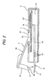
- Fig. 2 is a longitudinal sectional view of the surgical staple remover shown in Fig. 1 .
- Fig. 3A is an explanatory view of an illustrative embodiment of removing a surgical staple.
- Fig. 3B is another explanatory view of the illustrative embodiment of removing the surgical staple.
- Fig. 4 is a longitudinal sectional view of the surgical staple remover taking in the removed surgical staples.
- Fig. 5 is a partially enlarged view of Fig. 4 .
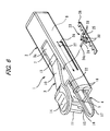
- Fig. 6 is a perspective view of a surgical staple remover according to a second embodiment of the present invention.
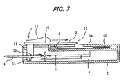
- Fig. 7 is a longitudinal sectional view of the surgical staple remover shown in Fig. 6 taking in a surgical staple.
- Fig. 8 is a partially enlarged view of Fig. 7 .
- Fig. 1 is a perspective view of a surgical staple remover according to a first embodiment of the present invention
- Fig. 2 is a longitudinal sectional view thereof.
- the surgical staple remover 1 includes a body 2, a pressing slider 3 and a supporting member 4.
- the body 2 is formed of transparent synthetic resin in a slender box shape.
- a take-in opening 5 is formed at the front end of the body 2.
- the body 2 has a storage portion 6 inside which a space is formed.
- the take-in opening 5 is communicated with the storage portion 6.
- a guide groove 7 is formed along the longitudinal direction of the body 2. Below the guide groove 7, a guiding passage 8 is formed.
- the body 2 may not necessarily be transparent in so far as the inner side of the storage portion 6 is visible from outside.
- the storage portion 6 may be formed with a slit-shaped see-through window through which the inner side can be seen.
- the pressing slider 3 includes a slider block 3a, a pressing lever 10 and a staple pusher 11.
- the slider block 3a is slidably provided in the guiding passage 8 and is constantly biased forward by a spring 12.
- a protrusion 13 is formed on top of the slider block 3a. The protrusion 13 is engaged with the guide groove 7 and limits the moving end of the slider block 3a when sliding from the front side toward the rear side.
- the pressing lever 10 protrudes obliquely forward from the front end of the protrusion 13 and is formed with a finger rest 14 at a front distal portion thereof.
- the pressing lever 10 is made of an elastic material so that it is deformable by a downward deflection from a base portion thereof.
- the staple pusher 11 protrudes downward below the finger rest 14.
- a distal head portion of the staple pusher 11 is formed with an engaging part 15, and a pressing part 16 is formed to a rear side of the engaging part 15.
- the engaging part 15 protrudes more downward than the pressing part 16.
- the staple pusher 11 is preferably formed of a hard material such as metal because it is required to have strength.
- the staple pusher 11 may be formed of a resin material as long as it has sufficient strength and rigidity to press down a crown 20a of a surgical staple 20.
- the supporting member 4 is made of metal and has a U-shaped staple supporter 17 at a front portion thereof.
- the supporting member 4 further has a pair of parallel staple receivers 18 which are continuously formed from the staple supporter 17 in a rearward direction.
- the staple supporter 17 is inserted between a surgical staple 20, which has been bent by a surgical stapler, and a skin 19 to support both sides of the crown 20a of the surgical staple 20 from below.
- the width of the staple supporter 17 is slightly narrower than the width of the crown 20a of the surgical staple 20.
- the staple supporter 17 is formed to have a thin wall thickness so that it can be easily inserted between the crown 20a and the skin 19.
- the staple supporter 17 protrudes forward from the take-in opening 5.
- the staple receivers 18 are arranged inside the storage portion 6 and are secured by suitable means.
- the staple receivers 18 are formed with continuous engaging indentations 22.
- the engaging indentations 22 are formed between serrated teeth, and the interval between the engaging indentations 22 that are adjacent to each other in the front-rear direction is set to have a length about 1 to 1.5 times as wide as the thickness of the staple 20.
- the foremost (nearest to the staple supporter 17) engaging indentations 22a are set to be positioned substantially immediately above the rear face of the engaging part 15 when the pressing slider 3 is slid to the rear side moving end.
- the number of the engaging indentations 22 may be determined in accordance with the number of surgery staples used in a usual surgical operation (about 30 to 60).
- the staple supporter 17 of the supporting member 4 is inserted below the crown 20a of the surgical staple 20 used to suture the wound as shown in Fig. 3A to support the lower portions of both sides of the crown 20a with the staple supporter 17.
- the pressing lever 10 is deflected downward, whereby the pressing part 16 of the staple pusher 11 engages with the upper central portion of the crown 20a of the surgical staple 20.
- the pressing lever 10 When the pressing lever 10 further deflected downward by applying a force onto the finger rest 14, the upper central portion is pressed downward by the pressing part 16 from above while the lower side portions being supported by the staple supporter 17, whereby the crown 20a of the surgical staple 20 is deformed to be bent in a U-shape as shown in Fig. 3B .
- the entire surgical staple 20 is deformed in an M-shape, and the legs 20b on respective sides are removed from the skin 19.
- the pressing slider 3 After removing the surgical staple 20 in this way, the pressing slider 3 is rearwardly slid against the spring 12 as shown in Fig. 4 , whereby the surgical staple 20 engages with the engaging part 15 of the staple pusher 11 and is taken into the storage portion 6 from the take-in opening 5.
- the rear face of the engaging part 15 of the pressing slider 3 is located at the position corresponding to the foremost engaging indentations 22a as shown in Fig. 5 . Accordingly, the surgical staple 20 thus taken in is supported in engagement with the foremost engaging indentations 22a. Thereafter, when the force is released from the pressing slider 3, the pressing slider 3 is moved to be restored to its initial position by the elastic force of the spring 12. Even when the pressing slider 3 is returned to the initial position, the surgical staple 20 is still stably supported by the pair of parallel staple receivers 18 and is engaged with the engaging indentations 22 each formed between the serrated teeth. Thus, the surgical staple 20 cannot move in a returning direction (in a forward direction) and is held in the same position.
- the subsequent surgical staple 20 is removed by the operation of the pressing slider 3, and is taken into the storage portion 6 from the take-in opening 5 by the rearward slide of the pressing slider 3. Further, when the pressing slider 3 reaches the moving end, the surgical staple 20 taken in is pushed into the foremost engaging indentations 22a. At this time, the preceding surgical staple 20 which has been held in the engaging indentations 22a is forcibly pushed out rearward. Since the rear sides of the engaging indentations 22 are gently sloped, the surgical staple 20 pushed out is smoothly pushed into engaging indentations 22b on the rear side.
- the interval between the adjacent engaging indentations 22 is set to have a length of about 1 to 1.5 times as wide as the thickness of the staple 20, the pushed out surgical staple 20 is supported in engagement with the subsequent engaging indentation 22b. Thereafter, when a force is released from the pressing slider 3 to restore the pressing slider 3 back to the initial position by the elastic force of the spring 12, the surgical staples 20 engaged in the two sets of engaging indentations 22a, 22b are held in their respective positions. Likewise, the removed surgical staples 20 are held in such a manner that they are sequentially arranged in the engaging indentations 22 of the staple receivers 18 toward the rear side.
- the height of the storage portion 6 is preferably slightly higher than the height of the removed surgical staples 20. More specifically, the storage portion 6 is preferably formed such that the upper face of the storage portion 6 is slightly higher than the upper edges of the surgical staples 20 supported on the staple receivers 18 and such that the lower face of the storage portion 6 is slightly lower than the lower ends of the surgical staple 20 supported on the staple receivers 18. According to such a configuration, even when the surgical staple remover 1 is slightly tilted or moved, the surgical staples 20 held inside the storage portion 6 are unlikely to move out of the respective engaging indentations 22 and are firmly held and supported on the staple receivers 18.
- the engaging indentations 22 may not necessarily be serrated.
- the engaging indentations 22 may be in a continuously corrugated form.
- the body 2 or the staple receivers 18 may be changed in color or calibrated so that the surgical staples 20 can be counted quickly and reliably.
- Fig. 6 is a perspective view of a surgical staple remover according to a second embodiment of the present invention
- Fig. 7 is a longitudinal sectional view thereof.
- components that are similar to those of the first embodiment are denoted by same reference numerals, and explanation thereof will be omitted.
- the surgical staple remover 1 further includes a counter 23 which counts the surgical staples 20 that are rearwardly moved from the staple supporter 17 of the supporting member 4 by the pressing slider 3.
- the counter 23 includes a gear wheel 24 which is enagageable with the surgical staples 20 that are rearwardly moving from the staple supporter 17 by the pressing slider 3, a rack member 25 interlocks with the rotation of the gear wheel 24, an indicator 26 provided on an end portion of the rack member 25, and a scale 27 marked on one of the sidewalls of the storage portion 6.
- the gear wheel 24 has four teeth 28 formed in the shape of a cross, one of which meshing with one of indent grooves 30 formed on the rack member 25.
- a rotating axis 24a of the gear wheel 24 is rotatably supported inside the storage portion 6 by suitable means. When the gear wheel 24 rotates, the rack member 25 and indicator 26 also move interlockingly therewith.
- the scale 27 is provided along a direction in which the indicator 26 moves along the inner face of the side wall of the storage portion 6. Further, at least a portion of the side wall of the storage portion 6 around the scale 27 is formed such that the indicator 26 is visible.
- the surgical staples 20 moving rearward from the staple supporter 17 of the supporting member 4 by the pressing slider 3 are counted by the counter 23.
- the surgical staple 20 moves along the staple receivers 18, it engages with one of the teeth 28 of the gear wheel 24, whereby the gear wheel 24 is rotated.
- the gear wheel 24 rotates, as shown in Figs. 6 and 8 , the tooth 28, which is located on the opposite side of the tooth 28 engaging with the surgical staple 20, forwardly pushes the rack member 25, whereby the rack member 25 and the indicator 26 are moved forward along the scale 27 by one scale unit.
- the indicator 26 interlockingly moves by one unit of the scale 27 so that one surgical staple 20 is counted.
- the number of the surgical staples 20 is similarly counted up by one, and the number of the surgical staples 20 is indicated by the indicator 26 and the scale 27. Accordingly, the total number of the removed surgical staples 20 can be easily determined by the indication of the indicator 26 and the scale 27.
- the number of the surgical staples 20 removed is automatically counted and indicated. Therefore, it is not necessary to directly look and count the surgical staples one by one. Thus, a surgeon can easily and reliably confirm whether or not the number of the surgical staples 20 used for the suturation is equal to the number of the surgical staples 20 removed.
- the counter 23 includes the gear wheel 24 enagageable with the surgical staple 20 which is rearwardly moved by the pressing slider 3, and the indicator 26 which moves interlockingly with the rotation of the gear wheel 24. That is, since the number of the surgical staples 20 removed is mechanically counted and indicated, no electric power supply is required.
- the configuration of the counter 23 is not limited to the configuration described above.
- the counter may be configured in an arc shape.
- electrical contacts may be provided at positions through which the surgical staple 20 passes, and the counter may count up the number of the surgical staples 20 when the surgical staple 20 taken in is brought into contact with the electrical contacts so that a current is carried therethrough. In this case, because the mechanical portions can be reduced, an increase in the weight of the surgical staple remover can be minimized.
- a surgical staple remover in which the number of surgical staples removed is reliably and safely countable can be provided.
Landscapes
- Health & Medical Sciences (AREA)
- Life Sciences & Earth Sciences (AREA)
- Surgery (AREA)
- Heart & Thoracic Surgery (AREA)
- Engineering & Computer Science (AREA)
- Biomedical Technology (AREA)
- Nuclear Medicine, Radiotherapy & Molecular Imaging (AREA)
- Medical Informatics (AREA)
- Molecular Biology (AREA)
- Animal Behavior & Ethology (AREA)
- General Health & Medical Sciences (AREA)
- Public Health (AREA)
- Veterinary Medicine (AREA)
- Surgical Instruments (AREA)
Abstract
A surgical staple remover includes a staple supporter which is inserted below side portions of a crown of a surgical staple, which is joined to a skin, to support the surgical staple, a pressing slider which presses the crown of the surgical staple, which is supported by the staple supporter, to deform the surgical staple and to remove the surgical staple out from the skin and moves the surgical staple into a storage portion along a staple receiver which is continuously formed from the staple supporter. The number of the surgical staples inside the storage portion can be reliably and easily counted.
Description
- The present invention relates to a surgical staple remover for removing surgical staples used to suture a skin wound.
- Generally, when removing surgical staples using a surgical staple remover, the removed staples are required, in view of hygiene management, to be placed in a tray which is set at an appropriate location. However, when transferring the removed surgical staples from a patient's wound to the tray, there is a risk that the surgical staples may drop on the floor and get scattered and lost. Further, because the surgical staples transferred into the tray are exposed, the surgical staples may come in contact with a hand of a nurse or a disposer.
- Therefore, in consideration of safety, there has been developed a surgical staple remover which can immediately slide the removed surgical staple to move it into a safe storage portion (see, e.g.,
JP 2006-158503 A - Meanwhile, when removing the surgical staples, the removed surgical staples must be counted so that no surgical staples are left unremoved. This is because the number of surgical staples used for suturation is recorded on a medical chart during a surgery, and it can be said that the surgery is completed only after confirming that the same number of surgical staples as the used surgical staples are removed.
- However, the number of surgical staples removed cannot be recognized only by storing the surgical staples in the storage portion. Further, even if the storage portion is made transparent, the number of the surgical staples is hard to count when the surgical staples are overlapping each other. Moreover, there has been a problem of miscounting when the number of surgical staples is large.
- One or more embodiments of the present invention provide a surgical staple remover in which the number of surgical staples removed is easily and reliably countable.
- According to one or more embodiments of the present invention, a surgical staple remover includes a body having a storage portion, a staple receiver fixed inside the storage portion, a staple supporter formed continuously from the staple receiver to forwardly protrude from the body, and a pressing slider slidably attached to the body. The staple supporter supports lower side portions of a crown of a surgical staple which joined to a skin. The pressing slider presses the crown of the surgical staple, which is supported by the staple supporter, to deform the surgical staple. Further, the pressing slider moves the surgical staple into the storage portion along the staple receiver by rearwardly sliding with respect to the body. The body is formed such that an inner side of the storage portion is visible from outside. The staple receiver is formed with a plurality of engaging indentations, each being enagageable with the surgical staple.
- According to one or more embodiments of the present invention, a surgical staple remover includes a body having a storage portion, a staple receiver fixed inside the storage portion, a staple supporter formed continuously from the staple receiver to forwardly protrude from the body, a pressing slider slidably attached to the body, and a counter. The staple supporter supports lower side portions of a crown of a surgical staple which is joined to a skin. The pressing slider presses the crown of the surgical staple, which is supported by the staple supporter, to deform the surgical staple. Further, the pressing slider moves the surgical staple into the storage portion along the staple receiver by rearwardly sliding with respect to the body. The counter counts the surgical staple which is moved into the storage portion by the pressing slider.
-
Fig. 1 is a perspective view of a surgical staple remover according to a first embodiment of the present invention.
Fig. 2 is a longitudinal sectional view of the surgical staple remover shown inFig. 1 .
Fig. 3A is an explanatory view of an illustrative embodiment of removing a surgical staple.
Fig. 3B is another explanatory view of the illustrative embodiment of removing the surgical staple.
Fig. 4 is a longitudinal sectional view of the surgical staple remover taking in the removed surgical staples.
Fig. 5 is a partially enlarged view ofFig. 4 .
Fig. 6 is a perspective view of a surgical staple remover according to a second embodiment of the present invention.
Fig. 7 is a longitudinal sectional view of the surgical staple remover shown inFig. 6 taking in a surgical staple.
Fig. 8 is a partially enlarged view ofFig. 7 . -
- 1
- surgical staple remover
- 3
- pressing slider
- 4
- supporting member
- 6
- storage portion
- 17
- staple supporter
- 18
- staple receiver
- 20
- surgical staple
- 22
- engaging indentation
- 23
- counter
- Hereinafter, embodiments of the present invention will be described with reference to the drawings.
-
Fig. 1 is a perspective view of a surgical staple remover according to a first embodiment of the present invention, andFig. 2 is a longitudinal sectional view thereof. As shown inFig. 1 , thesurgical staple remover 1 includes abody 2, apressing slider 3 and a supportingmember 4. - The
body 2 is formed of transparent synthetic resin in a slender box shape. At the front end of thebody 2, a take-inopening 5 is formed. Further, thebody 2 has astorage portion 6 inside which a space is formed. The take-inopening 5 is communicated with thestorage portion 6. At the central portion of an upper part of thebody 2, aguide groove 7 is formed along the longitudinal direction of thebody 2. Below theguide groove 7, a guidingpassage 8 is formed. Thebody 2 may not necessarily be transparent in so far as the inner side of thestorage portion 6 is visible from outside. For example, thestorage portion 6 may be formed with a slit-shaped see-through window through which the inner side can be seen. - The
pressing slider 3 includes aslider block 3a, apressing lever 10 and astaple pusher 11. Theslider block 3a is slidably provided in theguiding passage 8 and is constantly biased forward by aspring 12. On top of theslider block 3a, aprotrusion 13 is formed. Theprotrusion 13 is engaged with theguide groove 7 and limits the moving end of theslider block 3a when sliding from the front side toward the rear side. - The
pressing lever 10 protrudes obliquely forward from the front end of theprotrusion 13 and is formed with afinger rest 14 at a front distal portion thereof. Thepressing lever 10 is made of an elastic material so that it is deformable by a downward deflection from a base portion thereof. - The
staple pusher 11 protrudes downward below thefinger rest 14. A distal head portion of thestaple pusher 11 is formed with anengaging part 15, and apressing part 16 is formed to a rear side of theengaging part 15. The engagingpart 15 protrudes more downward than thepressing part 16. Thestaple pusher 11 is preferably formed of a hard material such as metal because it is required to have strength. However, thestaple pusher 11 may be formed of a resin material as long as it has sufficient strength and rigidity to press down acrown 20a of asurgical staple 20. - The supporting
member 4 is made of metal and has aU-shaped staple supporter 17 at a front portion thereof. The supportingmember 4 further has a pair of parallelstaple receivers 18 which are continuously formed from thestaple supporter 17 in a rearward direction. As shown inFig. 3A , thestaple supporter 17 is inserted between asurgical staple 20, which has been bent by a surgical stapler, and askin 19 to support both sides of thecrown 20a of thesurgical staple 20 from below. The width of thestaple supporter 17 is slightly narrower than the width of thecrown 20a of thesurgical staple 20. Further, thestaple supporter 17 is formed to have a thin wall thickness so that it can be easily inserted between thecrown 20a and theskin 19. - The
staple supporter 17 protrudes forward from the take-inopening 5. Thestaple receivers 18 are arranged inside thestorage portion 6 and are secured by suitable means. Thestaple receivers 18 are formed with continuous engagingindentations 22. The engagingindentations 22 are formed between serrated teeth, and the interval between the engagingindentations 22 that are adjacent to each other in the front-rear direction is set to have a length about 1 to 1.5 times as wide as the thickness of thestaple 20. - The foremost (nearest to the staple supporter 17) engaging
indentations 22a are set to be positioned substantially immediately above the rear face of theengaging part 15 when thepressing slider 3 is slid to the rear side moving end. The number of the engagingindentations 22 may be determined in accordance with the number of surgery staples used in a usual surgical operation (about 30 to 60). - Next, the operation of the
surgical staple remover 1 will be described. First, holding thebody 2 with one hand, thestaple supporter 17 of the supportingmember 4 is inserted below thecrown 20a of thesurgical staple 20 used to suture the wound as shown inFig. 3A to support the lower portions of both sides of thecrown 20a with thestaple supporter 17. Next, placing the finger tip on thefinger rest 14 of thepressing slider 3, the pressinglever 10 is deflected downward, whereby thepressing part 16 of thestaple pusher 11 engages with the upper central portion of thecrown 20a of thesurgical staple 20. When thepressing lever 10 further deflected downward by applying a force onto thefinger rest 14, the upper central portion is pressed downward by thepressing part 16 from above while the lower side portions being supported by thestaple supporter 17, whereby thecrown 20a of thesurgical staple 20 is deformed to be bent in a U-shape as shown inFig. 3B . As a result, the entiresurgical staple 20 is deformed in an M-shape, and thelegs 20b on respective sides are removed from theskin 19. After removing thesurgical staple 20 in this way, thepressing slider 3 is rearwardly slid against thespring 12 as shown inFig. 4 , whereby thesurgical staple 20 engages with the engagingpart 15 of thestaple pusher 11 and is taken into thestorage portion 6 from the take-inopening 5. When thepressing slider 3 is slid to the moving end, the rear face of theengaging part 15 of thepressing slider 3 is located at the position corresponding to the foremost engagingindentations 22a as shown inFig. 5 . Accordingly, thesurgical staple 20 thus taken in is supported in engagement with the foremost engagingindentations 22a. Thereafter, when the force is released from thepressing slider 3, thepressing slider 3 is moved to be restored to its initial position by the elastic force of thespring 12. Even when thepressing slider 3 is returned to the initial position, thesurgical staple 20 is still stably supported by the pair of parallelstaple receivers 18 and is engaged with the engagingindentations 22 each formed between the serrated teeth. Thus, thesurgical staple 20 cannot move in a returning direction (in a forward direction) and is held in the same position. - Similarly, the subsequent
surgical staple 20 is removed by the operation of thepressing slider 3, and is taken into thestorage portion 6 from the take-inopening 5 by the rearward slide of thepressing slider 3. Further, when thepressing slider 3 reaches the moving end, thesurgical staple 20 taken in is pushed into the foremost engagingindentations 22a. At this time, the precedingsurgical staple 20 which has been held in the engagingindentations 22a is forcibly pushed out rearward. Since the rear sides of the engagingindentations 22 are gently sloped, thesurgical staple 20 pushed out is smoothly pushed into engagingindentations 22b on the rear side. Because the interval between the adjacent engagingindentations 22 is set to have a length of about 1 to 1.5 times as wide as the thickness of the staple 20, the pushed outsurgical staple 20 is supported in engagement with the subsequentengaging indentation 22b. Thereafter, when a force is released from thepressing slider 3 to restore thepressing slider 3 back to the initial position by the elastic force of thespring 12, thesurgical staples 20 engaged in the two sets of engagingindentations surgical staples 20 are held in such a manner that they are sequentially arranged in the engagingindentations 22 of thestaple receivers 18 toward the rear side. - When the final
surgical staple 20 is engaged in the foremost engagingindentations 22a, all of the removedsurgical staples 20 are held in the engagingindentations 22 of the pair of parallelstaple receivers 18, so that they are stably held in their orderly arranged state. Therefore, the number of thesurgical staples 20 removed can be counted by visually checking from the side of thebody 2. In this way, a surgeon can easily and reliably confirm whether or not the number of the surgical staples used for the suturation is equal to the number of the surgical staples removed. - The height of the
storage portion 6 is preferably slightly higher than the height of the removedsurgical staples 20. More specifically, thestorage portion 6 is preferably formed such that the upper face of thestorage portion 6 is slightly higher than the upper edges of thesurgical staples 20 supported on thestaple receivers 18 and such that the lower face of thestorage portion 6 is slightly lower than the lower ends of thesurgical staple 20 supported on thestaple receivers 18. According to such a configuration, even when thesurgical staple remover 1 is slightly tilted or moved, thesurgical staples 20 held inside thestorage portion 6 are unlikely to move out of the respective engagingindentations 22 and are firmly held and supported on thestaple receivers 18. - The engaging
indentations 22 may not necessarily be serrated. For example, the engagingindentations 22 may be in a continuously corrugated form. - Further, for each length corresponding to a certain number (e.g. 10) of the
surgical staples 20 supported side by side on thestaple receivers 18, thebody 2 or thestaple receivers 18 may be changed in color or calibrated so that thesurgical staples 20 can be counted quickly and reliably. -
Fig. 6 is a perspective view of a surgical staple remover according to a second embodiment of the present invention, andFig. 7 is a longitudinal sectional view thereof. In the second embodiment, components that are similar to those of the first embodiment are denoted by same reference numerals, and explanation thereof will be omitted. - The
surgical staple remover 1 according to the second embodiment further includes acounter 23 which counts thesurgical staples 20 that are rearwardly moved from thestaple supporter 17 of the supportingmember 4 by thepressing slider 3. - As shown in
Fig. 6 , thecounter 23 includes agear wheel 24 which is enagageable with thesurgical staples 20 that are rearwardly moving from thestaple supporter 17 by thepressing slider 3, arack member 25 interlocks with the rotation of thegear wheel 24, anindicator 26 provided on an end portion of therack member 25, and ascale 27 marked on one of the sidewalls of thestorage portion 6. Thegear wheel 24 has fourteeth 28 formed in the shape of a cross, one of which meshing with one ofindent grooves 30 formed on therack member 25. Arotating axis 24a of thegear wheel 24 is rotatably supported inside thestorage portion 6 by suitable means. When thegear wheel 24 rotates, therack member 25 andindicator 26 also move interlockingly therewith. Thescale 27 is provided along a direction in which theindicator 26 moves along the inner face of the side wall of thestorage portion 6. Further, at least a portion of the side wall of thestorage portion 6 around thescale 27 is formed such that theindicator 26 is visible. - As described above, the
surgical staples 20 moving rearward from thestaple supporter 17 of the supportingmember 4 by thepressing slider 3 are counted by thecounter 23. Specifically, as shown inFigs. 7 and8 , when thesurgical staple 20 moves along thestaple receivers 18, it engages with one of theteeth 28 of thegear wheel 24, whereby thegear wheel 24 is rotated. When thegear wheel 24 rotates, as shown inFigs. 6 and8 , thetooth 28, which is located on the opposite side of thetooth 28 engaging with thesurgical staple 20, forwardly pushes therack member 25, whereby therack member 25 and theindicator 26 are moved forward along thescale 27 by one scale unit. In this way, when thegear wheel 24 rotates, theindicator 26 interlockingly moves by one unit of thescale 27 so that onesurgical staple 20 is counted. When the subsequentsurgical staple 20 is taken in, the number of thesurgical staples 20 is similarly counted up by one, and the number of thesurgical staples 20 is indicated by theindicator 26 and thescale 27. Accordingly, the total number of the removedsurgical staples 20 can be easily determined by the indication of theindicator 26 and thescale 27. - According to the second embodiment, the number of the
surgical staples 20 removed is automatically counted and indicated. Therefore, it is not necessary to directly look and count the surgical staples one by one. Thus, a surgeon can easily and reliably confirm whether or not the number of thesurgical staples 20 used for the suturation is equal to the number of thesurgical staples 20 removed. - The
counter 23 includes thegear wheel 24 enagageable with thesurgical staple 20 which is rearwardly moved by thepressing slider 3, and theindicator 26 which moves interlockingly with the rotation of thegear wheel 24. That is, since the number of thesurgical staples 20 removed is mechanically counted and indicated, no electric power supply is required. - The configuration of the
counter 23 is not limited to the configuration described above. For example, the counter may be configured in an arc shape. Further, electrical contacts may be provided at positions through which thesurgical staple 20 passes, and the counter may count up the number of thesurgical staples 20 when thesurgical staple 20 taken in is brought into contact with the electrical contacts so that a current is carried therethrough. In this case, because the mechanical portions can be reduced, an increase in the weight of the surgical staple remover can be minimized. - While the present invention has been described in detail with reference to specific embodiments, it is apparent to those skilled in the art that various changes and modifications can be made therein without departing from the spirit and scope of the present invention.
- This application is based on Japanese Patent Application No.
2006-216832 filed on August 9, 2006 2007-035088 filed on February 15, 2007 - A surgical staple remover in which the number of surgical staples removed is reliably and safely countable can be provided.
Claims (10)
- A surgical staple remover comprising:a body comprising a storage portion;a staple receiver fixed inside the storage portion;a staple supporter formed continuously from the staple receiver to forwardly protrude from the body; anda pressing slider slidably attached to the body,wherein the staple supporter is configured to support lower side portions of a crown of a surgical staple which is joined to a skin,
the pressing slider is configured to press the crown of the surgical staple, which is supported by the staple supporter, to deform the surgical staple, and to move the surgical staple into the storage portion along the staple receiver by rearwardly sliding with respect to the body,
the body is formed such that an inner side of the storage portion is visible from outside, and
the staple receiver is formed with a plurality of engaging indentations, each being enagageable with the surgical staple. - The surgical staple remover according to claim 1, wherein the engaging indentation nearest to the staple supporter is formed at a position where the surgical staple, which is moved by the pressing slider, is engageable when the pressing slider is slid to the rearmost position.
- The surgical staple remover according to claim 1, wherein the plurality of engaging indentations are serrated.
- The surgical staple remover according to claim 1, wherein the body is formed of a transparent material.
- The surgical staple remover according to claim 1, further comprising a counter configured to count the surgical staple which is moved into the storage portion by the pressing slider.
- The surgical staple remover according to claim 5, wherein the counter comprises:a gear wheel rotatably supported inside the storage portion;an indicator which moves interlockingly with a rotation of the gear wheel; anda scale provided along a direction in which the indicator moves,wherein the gear wheel rotates when the surgical staple engages with the gear wheel while the surgical staple is being moved into the storage portion by the pressing slider.
- The surgical staple remover according to claim 5, wherein the counter counts up the surgical staple when a current is carried through the surgical staple while the surgical staple is being moved into the storage portion by the pressing slider.
- A surgical staple remover comprising:a body comprising a storage portion;a staple receiver fixed inside the storage portion;a staple supporter formed continuously from the staple receiver to forwardly protrude from the body;a pressing slider slidably attached to the body; anda counter,wherein the staple supporter is configured to support lower side portions of a crown of a surgical staple which is joined to a skin,
the pressing slider is configured to press the crown of the surgical staple, which is supported by the staple supporter, to deform the surgical staple, and to move the surgical staple into the storage portion along the staple receiver by rearwardly sliding with respect to the body, and
the counter counts the surgical staple which is moved into the storage portion by the pressing slider. - The surgical staple remover according to claim 8, wherein the counter comprises:a gear wheel rotatably supported inside the storage portion;an indicator which-moves interlockingly with a rotation of the gear wheel; anda scale provided along a direction in which the indicator moves,wherein the gear wheel rotates when the surgical staple engages with the gear wheel while the surgical staple is being moved into the storage portion by the pressing slider.
- The surgical staple remover according to claim 8, wherein the counter counts up the surgical staple when a current is carried through the surgical staple while the surgical staple is being moved into the storage portion by the pressing slider.
Applications Claiming Priority (3)
| Application Number | Priority Date | Filing Date | Title |
|---|---|---|---|
| JP2006216832A JP4894402B2 (en) | 2006-08-09 | 2006-08-09 | Surgical staple remover |
| JP2007035088A JP5050553B2 (en) | 2007-02-15 | 2007-02-15 | Surgical staple remover |
| PCT/JP2007/065248 WO2008018378A1 (en) | 2006-08-09 | 2007-08-03 | Surgical staple remover |
Publications (1)
| Publication Number | Publication Date |
|---|---|
| EP2050400A1 true EP2050400A1 (en) | 2009-04-22 |
Family
ID=39032908
Family Applications (1)
| Application Number | Title | Priority Date | Filing Date |
|---|---|---|---|
| EP07791922A Withdrawn EP2050400A1 (en) | 2006-08-09 | 2007-08-03 | Surgical staple remover |
Country Status (4)
| Country | Link |
|---|---|
| US (1) | US20100228268A1 (en) |
| EP (1) | EP2050400A1 (en) |
| TW (1) | TW200814964A (en) |
| WO (1) | WO2008018378A1 (en) |
Cited By (1)
| Publication number | Priority date | Publication date | Assignee | Title |
|---|---|---|---|---|
| RU2489104C2 (en) * | 2011-06-06 | 2013-08-10 | Государственное учреждение здравоохранения "Кемеровская областная клиническая больница" | Device for removal of double-rod fixer from bone |
Families Citing this family (4)
| Publication number | Priority date | Publication date | Assignee | Title |
|---|---|---|---|---|
| US8579917B1 (en) * | 2013-02-18 | 2013-11-12 | Sinn Rx, LLC | Surgical staple remover with removable front end |
| EP3142571B1 (en) * | 2014-05-13 | 2019-10-30 | Gyrus ACMI, Inc. (D.B.A. Olympus Surgical Technologies America) | Mechanical converter assembly for lithotripsy device |
| CN110496268A (en) * | 2019-06-20 | 2019-11-26 | 苏州大学 | A kind of venous indwelling needle and its pulling device |
| US20210220023A1 (en) * | 2020-01-21 | 2021-07-22 | Warsaw Orthopedic, Inc. | Multi-cap removing-and-holding instrument for spinal surgeries |
Family Cites Families (8)
| Publication number | Priority date | Publication date | Assignee | Title |
|---|---|---|---|---|
| US4487394A (en) * | 1982-04-14 | 1984-12-11 | Senco Products, Inc. | Extractor for surgical staples |
| US4589631A (en) * | 1984-09-28 | 1986-05-20 | United States Surgical Corporation | Surgical staple remover |
| US5356064A (en) * | 1991-10-18 | 1994-10-18 | United States Surgical Corporation | Apparatus and method for applying surgical staples to attach an object to body tissue |
| GB9324029D0 (en) * | 1993-11-23 | 1994-01-12 | Khan Saheed | Staple remover with built-in storage chamber |
| JP4305375B2 (en) | 2004-12-03 | 2009-07-29 | マックス株式会社 | Surgical staple remover |
| JP4780295B2 (en) * | 2005-01-19 | 2011-09-28 | マックス株式会社 | Medical staples |
| JP2006216832A (en) | 2005-02-04 | 2006-08-17 | Matsushita Electric Ind Co Ltd | Manufacturing method of semiconductor device |
| JP4262227B2 (en) | 2005-07-22 | 2009-05-13 | シャープ株式会社 | Read circuit for semiconductor memory device |
-
2007
- 2007-08-03 US US12/376,503 patent/US20100228268A1/en not_active Abandoned
- 2007-08-03 TW TW096128570A patent/TW200814964A/en unknown
- 2007-08-03 EP EP07791922A patent/EP2050400A1/en not_active Withdrawn
- 2007-08-03 WO PCT/JP2007/065248 patent/WO2008018378A1/en not_active Ceased
Non-Patent Citations (1)
| Title |
|---|
| See references of WO2008018378A1 * |
Cited By (1)
| Publication number | Priority date | Publication date | Assignee | Title |
|---|---|---|---|---|
| RU2489104C2 (en) * | 2011-06-06 | 2013-08-10 | Государственное учреждение здравоохранения "Кемеровская областная клиническая больница" | Device for removal of double-rod fixer from bone |
Also Published As
| Publication number | Publication date |
|---|---|
| US20100228268A1 (en) | 2010-09-09 |
| TW200814964A (en) | 2008-04-01 |
| WO2008018378A1 (en) | 2008-02-14 |
Similar Documents
| Publication | Publication Date | Title |
|---|---|---|
| EP1790294A1 (en) | Stapler for medical application | |
| EP0000875B1 (en) | Hemostatic clip applicator | |
| US20100228268A1 (en) | Surgical staple remover | |
| US4850355A (en) | Hemostatic clip applicator for applying multiple hemostatic clips | |
| KR900004142B1 (en) | Ligature device | |
| EP2367483B1 (en) | Scalpel with removable blade assembly | |
| RU2623130C2 (en) | Linear suturing device | |
| EP1645232B1 (en) | Device for stocking, delivering and deploying surgical staples | |
| US10259642B2 (en) | Blade dispenser | |
| CN107205748B (en) | Surgical clip applier with multiple clip feed mechanisms | |
| JP2006081687A5 (en) | ||
| JPS6148347A (en) | Surgical instrument | |
| DK163561B (en) | SURGICAL ADAPTER | |
| JPH02232041A (en) | Clip applicator for operation | |
| JP2005193037A (en) | Surgical instrument adapted to apply multiple surgical fasteners to body tissue | |
| WO2015069992A1 (en) | Blade dispenser | |
| US4277236A (en) | Orthodontic instrument for applying elastic ligatures | |
| CN111616763B (en) | Staple cartridge assembly for a surgical instrument and surgical instrument | |
| SE445883B (en) | SURGICAL CLAMP REMOVER | |
| JP2019217300A (en) | Injector, lancet assembly, and puncture device | |
| JP7122326B2 (en) | Optical fiber cutting machine and optical fiber cutting method | |
| CN101489493A (en) | Surgical staple remover | |
| JP5050553B2 (en) | Surgical staple remover | |
| US12280247B2 (en) | Needle cover removing device and a method for removing the needle cover of an injection device | |
| JP2006081688A (en) | Medical stapler |
Legal Events
| Date | Code | Title | Description |
|---|---|---|---|
| PUAI | Public reference made under article 153(3) epc to a published international application that has entered the european phase |
Free format text: ORIGINAL CODE: 0009012 |
|
| 17P | Request for examination filed |
Effective date: 20090127 |
|
| AK | Designated contracting states |
Kind code of ref document: A1 Designated state(s): AT BE BG CH CY CZ DE DK EE ES FI FR GB GR HU IE IS IT LI LT LU LV MC MT NL PL PT RO SE SI SK TR |
|
| AX | Request for extension of the european patent |
Extension state: AL BA HR MK RS |
|
| DAX | Request for extension of the european patent (deleted) | ||
| RBV | Designated contracting states (corrected) |
Designated state(s): DE FR GB IT |
|
| STAA | Information on the status of an ep patent application or granted ep patent |
Free format text: STATUS: THE APPLICATION HAS BEEN WITHDRAWN |
|
| 18W | Application withdrawn |
Effective date: 20100303 |