EP2050323B1 - Semi-mounted reversible plough - Google Patents
Semi-mounted reversible plough Download PDFInfo
- Publication number
- EP2050323B1 EP2050323B1 EP08018257A EP08018257A EP2050323B1 EP 2050323 B1 EP2050323 B1 EP 2050323B1 EP 08018257 A EP08018257 A EP 08018257A EP 08018257 A EP08018257 A EP 08018257A EP 2050323 B1 EP2050323 B1 EP 2050323B1
- Authority
- EP
- European Patent Office
- Prior art keywords
- plough
- frame
- plow
- plow frame
- semimounted
- Prior art date
- Legal status (The legal status is an assumption and is not a legal conclusion. Google has not performed a legal analysis and makes no representation as to the accuracy of the status listed.)
- Not-in-force
Links
Images


Classifications
-
- A—HUMAN NECESSITIES
- A01—AGRICULTURE; FORESTRY; ANIMAL HUSBANDRY; HUNTING; TRAPPING; FISHING
- A01B—SOIL WORKING IN AGRICULTURE OR FORESTRY; PARTS, DETAILS, OR ACCESSORIES OF AGRICULTURAL MACHINES OR IMPLEMENTS, IN GENERAL
- A01B3/00—Ploughs with fixed plough-shares
- A01B3/46—Ploughs supported partly by tractor and partly by their own wheels
- A01B3/464—Alternating ploughs with frame rotating about a horizontal axis, e.g. turn-wrest ploughs
Definitions
- the invention relates to a semi-mounted reversible plow with a suitable for attachment to the lifting device of a towing vehicle, a rotary drive for the turning operation of a plurality of plow body bearing plow frame having plow head, the plow frame to a substantially horizontal and extending in the direction of the plow, by a pivot bearing on Plow head defined turning axis between two fixable working positions can be switched and its rear end is supported by a least a support wheel having Aufsattelfahrtechnik, which is provided with a pivot bearing for the plow frame, which is prevented by a connected to the plow head stabilizer tilting and a lifting device for lifting and lowering the plow frame.
- the lifting device is suitable for Aufsattel Kunststoffmaschinen, in cooperation with a towing vehicle provided at the end of the furrow plow frame so far raise that the plow body are lifted from the ground and the plow frame is ready for the turning process.
- the plow frame is lowered by the lifting device again.
- the plow frame is lifted above the saddle chassis.
- the plow frame is connected via a rotary arm with the pivot bearing on the saddle chassis. The radius of the turning circle described by the plow frame when changing the working position is determined by the length of the rotary arm.
- the length of the rotary arm is therefore such that, when lowered into the working position plow frame collision of jockey wheel and plow frame is avoided and on the other hand, the horizontal distance of the plow frame center of gravity from the facing boundary of the footprint of existing from the towing vehicle and associated with this Aufsattelcardpflug system As low as possible in order to avoid the risk of tilting of the system when excavated and in particular inclined on a slope plow.
- the longer the rotary arm and the further so that the plow frame center of gravity is removed from the pivot bearing the greater the torque that must be spent on the initiation of the turning process and the stronger the rotary drive must be dimensioned on the plow head.
- the invention has for its object to improve quite generally the stability of a Aufsattelcardpflugs, especially in the excavated plow frame to reduce the horizontal distance of the plow frame center of gravity from the pivot bearing, and thus to reduce both the danger of tipping and the required dimensioning of the rotary drive. It is also desirable to achieve the lowest possible center of gravity position in the transport position of the plow frame.
- the solution of this task according to the invention is that the at least one support wheel is mounted on a chassis body in a particular fixed position, that the pivot bearing is positioned in a particular fixed position on the chassis body that at the pivot bearing at least one connecting member is mounted to the plow frame, the is connected via a hinge with the plow frame such that the pivot angle between the plow frame and link is limited by a stop, that the link is attached to the saddle mounted drive such that starting from a laterally extending from the base body, one of the fixable working positions the plow frame associated basic position with fixed plow frame, the connecting member relative to the base body by raising the joint in the direction of an approximately vertical position is pivotable and the joint is blocked by the stop, w If the plow frame has reached the ground clearance required for the turning operation, and that a controller is suitable to release the fixation of the plow frame relative to the plow head when reaching the blocked position of the joint and turn on the rotary actuator.
- the rotary drive can be supported on the plow head by the drive until the plow frame has exceeded the apex of its turning movement and sinks by its own weight in the new working position, the drive takes over the damping.
- the center of gravity could be raised by about 30 cm.
- the pivot bearing can be arranged relatively low on Aufsattelfahrtechnik, which sets the center of gravity of the plow frame in the working position lower than in the prior art, whereby the danger of tipping for the plow is reduced.
- the stop prevents the plow frame from tipping back against the turning direction before the apex point is exceeded
- the drive on Aufsattelfahrtechnik and the power lift or the hydraulic lifting device of the towing vehicle when lifting the plow head together.
- the drive consists of two hydraulic cylinders, each associated with one of the two turning directions of the plow frame.
- each hydraulic cylinder is designed as an angle lever designed pendulum bracket
- the long leg is mounted with its upper end about an axis parallel to the pivot axis pivotally mounted on each of the sides of the body and at the bottom has a laterally protruding from the base short leg, to which one end of the hydraulic cylinder is connected, the pressure of the hydraulic cylinder being supported by abutment of the pendulum bracket on the base body.
- the connecting member consists of a pivot bearing mounted in the pivot bearing having two symmetrical with respect to its vertical center position, the two working positions of the plow frame associated end positions and a arranged on him, on a circular path about the pivot bearing movable joint is connected to the plow frame, and that on the pivot arm on both sides in the direction of rotation of the plow frame associated stops for each limitation of the pivot angle are arranged.
- the stops are designed as lateral projections of the pivot arm, wherein expediently the hydraulic cylinders of the drive are each connected to one of the stops.
- the connecting member is formed by a four-bar system whose base is a two-armed lever, which is mounted centrally on the pivot bearing and whose two ends each articulated via a link, each with one of two symmetrically arranged to the turning axis on the plow frame bearings are.
- the joint between the link and plow frame can move under the plow frame, which is the horizontal distance between Plow frame center of gravity and axis of the pivot bearing and thus reduces the applied for the pivoting of the plow frame torque.
- the vertical movement of the plow frame ie the maximum height of the plow center of gravity above the ground and thus the risk of tipping further reduced.
- the handlebars pivot in their bearing points on the plow frame.
- the angle between the lateral edge surface of the active hydraulic cylinder associated arm and the stop surface at the bearing reduces it until, after a predetermined excavation height of the plow frame, the facing surfaces on the handlebar and on the side of the plow frame parallel to each other and rest on each other, which prevents further angular movement between plow frame and handlebars. So that the handlebar can be moved further upwards and then over the vertical plane laid by the axis of the rotary bearing on the semi-mounted landing gear, the plow frame must be released for rotation about the turning axis.
- each plow body pair is assigned a common carrier and the angle between the cutting direction of the plow body and the longitudinal direction of the plow frame for each plow body pair is adjustable by each carrier associated with each plow body pair
- Rotary axis on the plow frame is adjustable and the support for joint adjustment of all plow body are connected at the same distance from the axis of rotation hinged to a rigid actuator, and the moving in the direction Aufsattelfahrtechnik must change its angle relative to the plow frame at a section width change.
- the plow frame is provided with a mounting bracket for connection to the Aufsattelfahrtechnik at which the at least one connecting member is connected, wherein the mounting bracket and a in their Area located on the plow frame mounted carrier, which has a with respect to its axis of rotation radially and approximately in the longitudinal direction of the plow frame to the extending link arm, two parallel gegengemertiegende members of a Gelenkparallelogramms form, the other two, with minimal cutting width adjustment obliquely backwards and mutually parallel members connect the mounting bracket on the one hand with the axis of rotation of the carrier and on the other hand with the distal end of the part of the carrier forming a link arm, and that the distance of the axis of rotation of the carrier of the parallel axis between plow frame and plow head is significantly longer than the distance of the parallel axes between the two ends of the stabilize
- Two mutually diagonally opposite hinge points of Gelenkparallelogramms are determined on the one hand by the respective position of the plow frame, on the other hand by the respective position of Aufsattelfahrtechniks, namely by the position of the axis of rotation of the plow carrier and on the other hand by the position of this axis of rotation diagonally opposite connection point of the mounting bracket with the free End of the link arm connecting parallelogram link.
- the angle between the plow frame and the plow head changes, and in the same sense the angle between the stabilizer and the plow head. Because of the above-defined difference in length of the radial distance of the axis of rotation of the carrier on the one hand and the point of articulation between Aufsattelfahrtechnik and stabilizer on the other hand from the respective connection point on the plow head, describes in the cutting width adjustment, the axis of rotation of the carrier an arc with a larger radius than that of the arc, the hinge point between the Saddle chassis and the stabilizer goes through, so when increasing the cutting width one exerted by the directed tensile force on the mounting bracket, so that the parallelogram is changed and the mounting bracket further away from the plow frame so that with each cutting width adjustment with respect to the center of gravity position of the plow frame optimal position between saddle and plow frame is maintained.
- the two directions of the plow frame associated stops between the connecting link and plow frame are preferably designed to be adjustable in order to vary the transition position between stroke movement and pivotal movement of the plow frame as desired.
- the present invention is based on the idea of dividing the plow frame described movement between the two working positions using a link between pivot bearing and plow frame in a plow frame parallel to itself lifting and at the same time the horizontal distance between plow frame center of gravity and pivot axis reducing movement phase or a the plow frame parallel to itself lowering and at the same time the horizontal distance between the plow frame center of gravity and pivot bearing axis again increasing motion phase and these two phases of motion interconnecting third movement phase in which the plow frame pivots 180 ° and its focus while at the same time in the horizontal direction of the one Moved side of the pivot bearing axis on the other side, has the advantageous consequence that the pivot bearing of the link on the saddle undercarriage according to the vertical movement of the P can be placed deeper in the first and second movement phase and the risk of tipping is reduced in upwardly displaced plow frame and the expended for pivoting the plow frame torque.
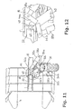
- a total of 10 designated embarktelwindpfluge consists of three main components, a connectable to a hydraulic lifting device of a tractor plow 12, a known manner plow body 14 carrying plow frame 16 and a rear portion of the plow frame 16 supporting Aufsattelfahrtechnik 18.
- the supporting element of the plow frame a square hollow section.
- the embarksattelfahrtechnik 18 has a likewise hydraulically actuated, hereinafter described in more detail device which is suitable to raise the plow frame in cooperation with the hydraulic lifting device of the towing vehicle so far that in the working position of the plow frame 16 lowered into the ground plow body 14 completely out of their in be lifted out of the ground penetrating position.
- the plow frame 16 can then by means of a pivot bearing 20 and a pair, for example in the Figures 22 . 29 . 33 and 36 shown, hydraulically actuated turning cylinder 31a and 31b relative to the plow head 12 about an approximately horizontal and extending in the direction of the plow 10 turning axis between two with respect to this axis offset by 180 °, are pivoted by stops defined working positions.
- the plow frame 16 is also rotatably mounted on the saddle chassis 18 in a manner to be described later.
- the plow frame 16 carries two groups of plow bodies 14 such that the plow body 14 are associated with each other in pairs and the plow body of a group in its working position the plaice - based on the working direction of the plow 10 - move to the right, while the plow bodies of the other group move the floe to the left in their working position.
- the terms horizontal and vertical are used in this description, this is done on the premise that regardless of the nature of the terrain, the ground surface used by the plow is considered to be the horizontal reference plane.
- the plow head 12 is designed for connection to a conventional three-point linkage with two hydraulically raisable and sinkable lower links and a top link and for this purpose has two common, approximately horizontally and transversely to the direction of axis extending, lateral pins 22 and 24 ( Fig. 1 ) for the lower links and a selection of connection holes 25 in the upper region of a vertical tower 26 for the articulated connection of the upper link.
- the Aufsattelfahrtechnik 18 is provided with at least one standing in constant contact with the ground wheel 28, which is supported by a fixedly connected to a base body 30 of Aufsattelfahrtechniks 18 forked arm 32. In order to prevent tilting of Aufsattelfahrtechniks 18, it is connected by a stabilizer 34 with the plow head 12, which is connected on both sides like a cross joint with a direction transverse to the horizontal axis and a vertical axis.
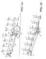
- the pivot arm 40 consists of two connected to common movement and in the axial direction congruent spaced apart band-shaped arms 40a and 40b, each of which is provided with stops 44a and 44b, with the plow head 12 facing the front of the pivot arm 40 and the back eg are firmly connected by welding.
- a hinge pin 46 extends, which passes through a joint sleeve 48, which at one in working position of the plow frame 16 is mounted in each case in the direction of the Aufsattelfahrtechnik 18 projecting bracket 50.
- the relative movement between the pivot arm 40 and the bracket 50 about the hinge pin 46 is limited by the abutment of one of the stops 44a and 44b on the bracket 50.
- the stops 44a and 44b can be made adjustable. For example, screws 50 interacting with the bracket 50 may be provided in these stops 44a and 44b.
- L-shaped pendulum supports 54a and 54b are pivotally mounted such that their long leg rests against an associated lateral abutment surface of the base body 30 while the short leg projects laterally approximately horizontally outwards.
- the short legs are each provided with a bearing pin 56a hrs.56b for articulated connection of a hydraulic actuating cylinder 58a and 58b.
- each actuating cylinder 58a and 58b between the pairwise associated stops 44a and 44b and the mutually associated pendulum supports 54a and 54b and also between the two arms of the pivot arm 40 is movable, as for example, clearly in Fig. 9 can be seen.
- the pendulum support 54 on the body, and associated with its actuating cylinder 58 has its shortest length and extends in the lateral direction to the associated stop 44.
- the dimensioning of the construction described is such that by the movement of the pivot arm 40 to the blocking function of the stop 44 of the plow frame 16 parallel to itself, d. H. essentially while maintaining its spatial orientation parallel to the starting position, as far as raised, that in the position reached the plow body 14 have left the ground and there is sufficient ground clearance for the turning process from one to the other working position. It is provided a control that cancels the rotational barrier of the plow frame 16 when reaching this position and thus allows the continuation of the pivotal movement of the pivot arm 40 with simultaneous rotation of the plow frame 16 in the pivot bearing 20.
- This lock can be exerted, for example, by the hydraulic turning cylinder on the plow head 12, which can be seen in some figures showing the later explained second embodiment.
- the controller may respond to the pressure increase in the actuator cylinder 58 upon reaching the stop position.
- the pivot arm 40 After the suspension of the blocking of the rotary movement of the plow frame 16, the pivot arm 40 is in its vertical position ( Fig. 18 pivoted and at the same time the plow frame 16 rotates relative to the pivot arm 40 in the in Fig. 18 shown transport position in which it can be blocked.
- the system of swing arm 40 and plow frame 16 continues to move and the plow frame center of gravity exceeds this apex position, so that the plow frame 16 strives under the influence of its weight to reach its new working position.
- the hitherto active actuating cylinder 58 is relieved and pulls the associated pendulum support 54 upwards.
- the adjusting cylinder 58 for damping the second phase of the turning movement be used.
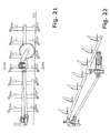
- the base of the four-bar link 100 forms a two-armed lever 102, which is mounted centrally pivotable in the pivot bearing 36 of the base body 30.
- two joints 104a and 104b are provided at the two free ends of the lever 102.
- the arranged on the plow frame 16 and together with this about the pivot axis defined by the bearings 20 and 36 movable console 50 is symmetrical with respect to the plane of symmetry of the mounted on the plow frame 16 pairs of plow bodies with two other joints 106a and 106b of the four-bar system 100 provided.
- a link 108a and 108b is arranged in each case.
- stops 110a and 110b are provided on the console, which are assigned to the outside of the four-bar hinge 100 facing side surfaces 112a and 112b of the handlebars 108a and 108b such that in the in the FIGS. 29 to 32 shown position in which locked in rotational movement of the plow frame 16, the upward movement of the plow frame 16 is parallel to itself and the continuation of this upward movement can take place only with simultaneous rotation of the plow frame 16 to the axis defined by the bearings 20 and 36 turning axis, so what Loosening the lock the rotational movement of the plow frame 16 requires.
- the movement steps of the turning process are shown in matching stages for both the first and second embodiments.
- the Fig. 1 shows the plow in a first working position in which seen in the direction of travel, the plow body 14 are right of the plow frame 16.
- the turning cylinders 31 a and 31 b ( Fig. 29 ) on the plow head 12 a rotation of the plow frame in the pivot bearing 20.
- the bracket 50 for the connection of Aufsattelfahrtechniks 18 is located on the left side of the plow frame 16 and - as from the 4 and 5 visible - the pivot arm 40 extends obliquely downwards to the bracket 50 and the stops 44a and 44b are spaced from the stop surfaces 51a and 51b on the bracket 50 so that a rotational movement of the pivot arm 40 in the pivot bearing 36 (FIG. Figures 18 and 19 ) is not impeded.
- the actuating cylinder 58a Fig. 4 shown pivoted position upwards.
- the turning cylinder 31 b comes into action to initiate the rotational movement of the plow frame 16 about the hinge pin 46.
- the plow frame 16 takes part in the further rotational movement of the pivot arm 40 when the hinge pin 46 moves in the vertex of its orbit and thereby the in the FIGS. 13 to 17 illustrated inclined position passes through and the plow frame 16 finally suitable for transport, in Fig. 18 achieved position, which can maintain the plow frame 16 when it is prevented by activation of the lock on the rotation in the bearing 20 again.
- the lock remains unlocked and the hinge pin 46 can pass through the vertex of the rotational movement, whereby now the weight of the plow frame 16 strives to move the plow frame 16 in the new working position, the positions of the FIGS. 1 to 19 now in reverse order and mirror image to be traversed by the rotary bearing 36 vertical plane.
- FIGS. 29 to 32 show the end of the vertical parallel movement of the plow frame 16 and the transition to its pivotal movement relative to the pivot bearing 36 after the side surface 112b abuts the stop 110b.
- the advantageous effect of the inventive design of the lifting and rotating device on the semi-trailer 18 can also be used in the turning device on the plow head 12.
- their application is also provided on the plow head, as clearly in the Fig. 33 It can be seen where one can recognize the support of the turning cylinder 31 b on the plow head 12 via a pivotally mounted on this pendulum support 154 a.
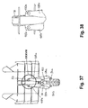
- FIGS. 40 to 46 show a device for cutting width adjustment, which is suitable for both embodiments, although a Aufsattelcardpflug is selected according to the second embodiment for the graphical representation of the basic construction.
- the FIGS. 40 to 42 show a plow in working position, the Fig. 40 the smallest cutting width, the Fig. 41 a middle and the Fig. 42 the largest cutting width shows.
- each pair of plow bodies 14 are each connected to a common carrier 60 which is pivotable about a respective vertical axis 62 in the working position of the plow relative to the plow frame 16.
- All beams 60 are pivotally connected to a control rod 64 which is connected via a link 66 with the plow head 12, so that the control rod 64 shifts relative to the plow frame 16, when by an actuating cylinder 68, the angle between the plow head 12 and the plow frame sixteenth is changed.
- the longitudinal movement of the control rod 64 causes a pivoting movement of the carrier 60 such that the horizontal pivoting movement of the plow frame the distance of the plow body transversely to the working direction and thus the cutting width changed, the alignment of the plow body 14 is maintained in the working direction.
- the distance between the contact point of the support wheel 28 and the plow frame center of gravity changes, so that starting from the optimum center of gravity position in the one end position of the plow frame 16 with increasing change in the cutting width reduce the benefits sought according to the invention, if not one additional device is able to compensate for the negative effect of the cutting width adjustment on the above-described construction according to the invention.
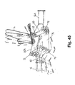
- This purpose is served by the particular configuration of the element 16A of the plow frame 16 connected to the semi-trailer chassis 18, on which a specially designed carrier 60A for one of the plow body pairs 14 is mounted pivotably about the plow frame 16 about one of the vertical axes 62.
- This support 16A is provided with a with respect to the axis 62 approximately radially and in the longitudinal direction of the plow frame 16 in the direction of the plow head 12 projecting arm 70, which has at its end remote from the axis 62 to the axis 62 axis-parallel joint 72.
- the handlebars 108a and 108b of Aufsattelfahrtechniks 18 are connected with their the plow frame 16 associated end to a console 74, which participates together with the plow frame 16 at the rotational movement about the pivot bearing 20 on the plow head and the pivot bearing 36 on Aufsattelfahrtechnik 18, but - as below yet described - while the cutting width adjustment in the horizontal direction is movable and thus also displaced to the console 74
- a console 74 which participates together with the plow frame 16 at the rotational movement about the pivot bearing 20 on the plow head and the pivot bearing 36 on Aufsattelfahrmaschine 18, but - as below yet described - while the cutting width adjustment in the horizontal direction is movable and thus also displaced to the console 74 Aufsattelfahrtechnik 18 moves.
- the bracket 74 consists of a plate-shaped main part 74a, which is provided with two axes 62 to the axis axis-parallel joints 76 and 78, the connecting line has the same length as the connecting path between the carrier 60A associated axis 62 and the joint 72 and parallel to it ,
- the hinge 76 and the aforementioned axle 62 are connected by a handlebar 80.
- the joints 72 and 78 are connected by a handlebar 80 parallel to the handlebar 82.
- the bracket 74 is thus incorporated into a parallelogram system, with the main portion 74a of the bracket 74 having a pommel head 12 projecting arm 74b to which the handlebars 108a and 108b are connected.
- the stops (eg 44 or 110) have been explained as fixed stops. It has also been pointed out that these stops can possibly be adjustable. According to a variant of the invention, not shown, it may also be provided that the respective stops can be placed in an inactive position, if necessary, in which you do not limit the pivot angle between the plow frame and the connecting member.
- the connecting member can then z. B. be pivoted starting from a respective working position of the plow frame in the vertical position, wherein the plow frame can assume an angled position or buckling relative thereto. In such a bent position, the arrangement can be locked for transport, so that a transport position with a relatively low center of gravity can be achieved.
Abstract
Description
Die Erfindung betrifft einen Aufsatteldrehpflug mit einem zur Befestigung an der Hubvorrichtung eines Zugfahrzeugs geeigneten, einen Drehantrieb für den Wendevorgang eines eine Mehrzahl von Pflugkörperpaaren tragenden Pflugrahmens aufweisenden Pflugkopf, wobei der Pflugrahmen um eine im wesentlichen horizontal und in Arbeitsrichtung des Pfluges verlaufende, durch ein Drehlager am Pflugkopf definierte Wendeachse zwischen zwei fixierbaren Arbeitsstellungen umstellbar ist und sein hinteres Ende von einem wenigsten ein Stützrad aufweisenden Aufsattelfahrwerk abgestützt ist, das mit einer Drehlagerung für den Pflugrahmen versehen ist, das über einen mit dem Pflugkopf verbundenen Stabilisator am Kippen gehindert ist und eine Hubvorrichtung zum Heben und Senken des Pflugrahmens aufweist.The invention relates to a semi-mounted reversible plow with a suitable for attachment to the lifting device of a towing vehicle, a rotary drive for the turning operation of a plurality of plow body bearing plow frame having plow head, the plow frame to a substantially horizontal and extending in the direction of the plow, by a pivot bearing on Plow head defined turning axis between two fixable working positions can be switched and its rear end is supported by a least a support wheel having Aufsattelfahrwerk, which is provided with a pivot bearing for the plow frame, which is prevented by a connected to the plow head stabilizer tilting and a lifting device for lifting and lowering the plow frame.
Bei bekannten Aufsatteldrehpflügen siehe z.B.
Bei Drehpflügen mit einer größeren Anzahl von Pflugkörperpaaren ragt der Pflugrahmen nach hinten über das Aufsattelfahrwerk hinaus und trägt dort ebenfalls wenigstens ein Pflugkörperpaar. In der Arbeitsposition liegt der Pflugrahmen relativ tief, etwa im Bereich der Radachse des Aufsattelfahrwerks. Die Länge des Dreharms ist deshalb so bemessen, daß bei in die Arbeitsposition abgesenktem Pflugrahmen eine Kollision von Stützrad und Pflugrahmen vermieden wird und andererseits der horizontale Abstand des Pflugrahmenschwerpunkts von der ihm zugewandten Begrenzung der Aufstandsfläche des aus dem Zugfahrzeug und dem mit diesem verbundenen Aufsatteldrehpflug bestehenden Systems möglichst gering ist, um die Gefahr des Kippens des Systems bei ausgehobenem und insbesondere bei am Hang schräg stehendem Pflug zu vermeiden. Je länger der Dreharm ist und je weiter damit der Pflugrahmenschwerpunkt von der Drehlagerung entfernt ist, desto größer ist das Drehmoment, das für die Einleitung des Wendevorgangs aufzuwenden ist und desto stärker muß der Drehantrieb am Pflugkopf dimensioniert sein.In rotary plows with a larger number of pairs of plow plow frame protrudes to the rear beyond the Aufsattelfahrwerk and also carries there at least one plow body pair. In the working position of the plow frame is relatively deep, such as in the area of the axle of the Aufsattelfahrwerks. The length of the rotary arm is therefore such that, when lowered into the working position plow frame collision of jockey wheel and plow frame is avoided and on the other hand, the horizontal distance of the plow frame center of gravity from the facing boundary of the footprint of existing from the towing vehicle and associated with this Aufsatteldrehpflug system As low as possible in order to avoid the risk of tilting of the system when excavated and in particular inclined on a slope plow. The longer the rotary arm and the further so that the plow frame center of gravity is removed from the pivot bearing, the greater the torque that must be spent on the initiation of the turning process and the stronger the rotary drive must be dimensioned on the plow head.
Der Erfindung liegt die Aufgabe zugrunde, ganz allgemein die Stabilität eines Aufsatteldrehpflugs zu verbessern, insbesondere beim ausgehobenen Pflugrahmen den horizontalen Abstand des Pflugrahmenschwerpunkts von der Drehlagerung zu verringern, und damit sowohl die Kippgefahr als auch die erforderliche Dimensionierung des Drehantriebs zu reduzieren. Außerdem wird angestrebt, in der Transportstellung des Pflugrahmens eine möglichst tiefe Schwerpunktsposition zu verwirklichen.The invention has for its object to improve quite generally the stability of a Aufsatteldrehpflugs, especially in the excavated plow frame to reduce the horizontal distance of the plow frame center of gravity from the pivot bearing, and thus to reduce both the danger of tipping and the required dimensioning of the rotary drive. It is also desirable to achieve the lowest possible center of gravity position in the transport position of the plow frame.
Die Lösung dieser Aufgabe besteht erfindungsgemäß darin, daß das wenigstens eine Stützrad an einem Fahrwerksgrundkörper in einer insbesondere festen Position gelagert ist, daß die Drehlagerung in einer insbesondere festen Position am Fahrwerksgrundkörper positioniert ist, daß an der Drehlagerung wenigstens ein Verbindungsglied zum Pflugrahmen gelagert ist, das über ein Gelenk mit dem Pflugrahmen derart verbunden ist, daß der Schwenkwinkel zwischen Pflugrahmen und Verbindungsglied durch einen Anschlag begrenzt ist, daß dem Verbindungsglied ein am Aufsattelfahrwerk angebrachter Antrieb derart zugeordnet ist, daß ausgehend von einer sich vom Grundkörper aus seitlich erstreckenden, einer der fixierbaren Arbeitsstellungen des Pflugrahmens zugeordneten Grundstellung bei fixiertem Pflugrahmen das Verbindungsglied gegenüber dem Grundkörper unter Anhebung des Gelenks in Richtung auf eine etwa vertikale Stellung verschwenkbar ist und das Gelenk durch den Anschlag blockiert ist, wenn der Pflugrahmen die für den Wendevorgang erforderliche Bodenfreiheit erreicht hat, und daß eine Steuerung geeignet ist, beim Erreichen der blockierten Stellung des Gelenks die Fixierung des Pflugrahmens gegenüber dem Pflugkopf zu lösen und den Drehantrieb einzuschalten.The solution of this task according to the invention is that the at least one support wheel is mounted on a chassis body in a particular fixed position, that the pivot bearing is positioned in a particular fixed position on the chassis body that at the pivot bearing at least one connecting member is mounted to the plow frame, the is connected via a hinge with the plow frame such that the pivot angle between the plow frame and link is limited by a stop, that the link is attached to the saddle mounted drive such that starting from a laterally extending from the base body, one of the fixable working positions the plow frame associated basic position with fixed plow frame, the connecting member relative to the base body by raising the joint in the direction of an approximately vertical position is pivotable and the joint is blocked by the stop, w If the plow frame has reached the ground clearance required for the turning operation, and that a controller is suitable to release the fixation of the plow frame relative to the plow head when reaching the blocked position of the joint and turn on the rotary actuator.
Ausgehend von einer der beiden Arbeitsstellungen des Pflugrahmens wird durch diese Konstruktion durch Betätigung des Antriebs am Aufsattelfahrwerk zunächst der an einer Drehung um die Wendeachse gehinderte Pflugrahmen parallel zu sich selbst angehoben, wobei sich der Winkel zwischen dem Pflugrahmen und dem Verbindungsglied verringert, bis schließlich der der jeweiligen Wenderichtung des Pflugrahmens zugeordnete Anschlag eine weitere Zerkleinerung des Winkels zwischen dem Pflugrahmen und dem Verbindungsglied und damit eine weitere Aufwärtsbewegung des Pflugrahmens parallel zu sich selbst verhindert. In dieser Position ist der Pflugrahmen so weit angehoben, daß die für die Wendebewegung um die Wendeachse erforderliche Bodenfreiheit erreicht ist. Es kann nun durch eine geeignete Steuerung die Fixierung des Pflugrahmens gelöst und mit Hilfe des Drehantriebs die Wendebewegung um die Wendeachse begonnen werden. Dabei hat sich - bevor der Anschlag greift und die Wendebewegung des Pflugrahmens um seine Wendeachse einsetzt - der Schwerpunkt des Pflugrahmens deutlich angehoben, aber auch sein horizontaler Abstand von der Achse der Drehlagerung verringert, so daß einerseits der Pflugrahmen ohne Kollisionsgefahr über das Aufsattelfahrwerk hinweggeschwenkt werden kann und andererseits das durch den Drehantrieb aufzuwendende Drehmoment reduziert wird, der somit kleiner dimensioniert werden kann. Zugleich ermöglicht es diese Konstruktion, beim Aufsattelfahrwerk Räder mit größerem Durchmesser einzusetzen. Außerdem kann der Drehantrieb am Pflugkopf durch den Antrieb unterstützt werden, bis der Pflugrahmen den Scheitelpunkt seiner Wendebewegung überschritten hat und durch sein eigenes Gewicht in die neue Arbeitsstellung absinkt, wobei der Antrieb die Dämpfung übernimmt. In der Praxis konnte der Schwerpunkt um etwa 30 cm angehoben werden. Das hat die vorteilhafte Folge, daß die Drehlagerung am Aufsattelfahrwerk relativ tief angeordnet werden kann, was in der Arbeitsstellung den Schwerpunkt des Pflugrahmens tiefer legt als beim Stand der Technik, wodurch die Kippgefahr für den Pflug verringert wird. Außerdem verhindert der Anschlag, daß vor dem Überschreiten des Scheitelpunkts der Pflugrahmen entgegen der Wenderichtung zurückkipptStarting from one of the two working positions of the plow frame is lifted by this construction by operating the drive on the semi-mounted first hindered against rotation about the turning axis plow frame parallel to itself, with the angle between the plow frame and the link is reduced until finally the respective turning direction of the plow frame associated stop further comminution of the angle between the plow frame and the connecting member and thus prevents further upward movement of the plow frame parallel to itself. In this position, the plow frame is raised so far that the required for the turning movement around the turning axis ground clearance is reached. It can now be solved by a suitable control the fixation of the plow frame and with the help of the rotary drive, the turning movement can be started around the turning axis. It has - before the attack engages and the turning movement of the plow frame uses its turning axis - the center of gravity of the plow frame significantly raised, but also reduces its horizontal distance from the axis of the pivot bearing so that on the one hand the plow frame can be swung over the saddle chassis without collision and on the other hand, the expended by the rotary drive torque is reduced, which can thus be made smaller. At the same time, this construction makes it possible to use wheels with larger diameters in the semi-trailer chassis. In addition, the rotary drive can be supported on the plow head by the drive until the plow frame has exceeded the apex of its turning movement and sinks by its own weight in the new working position, the drive takes over the damping. In practice, the center of gravity could be raised by about 30 cm. This has the advantageous consequence that the pivot bearing can be arranged relatively low on Aufsattelfahrwerk, which sets the center of gravity of the plow frame in the working position lower than in the prior art, whereby the danger of tipping for the plow is reduced. In addition, the stop prevents the plow frame from tipping back against the turning direction before the apex point is exceeded
Vorzugsweise wirken der Antrieb am Aufsattelfahrwerk und der Kraftheber bzw. die hydraulische Hubvorrichtung des Zugfahrzeuges beim Heben des Pflugkopfes zusammen.Preferably, the drive on Aufsattelfahrwerk and the power lift or the hydraulic lifting device of the towing vehicle when lifting the plow head together.
Nach einer bevorzugten Ausführungsform besteht der Antrieb aus zwei Hydraulikzylindern, die jeweils einer der beiden Wenderichtungen des Pflugrahmens zugeordnet sind.According to a preferred embodiment, the drive consists of two hydraulic cylinders, each associated with one of the two turning directions of the plow frame.
Dabei ist vorzugsweise jedem Hydraulikzylinder eine als Winkelhebel gestaltete Pendelkonsole zugeordnet, deren langer Schenkel mit seinem oberen Ende um eine zur Achse der Drehlagerung parallele Achse beweglich an jeweils einer der Seiten des Grundkörpers gelagert ist und am unteren Ende einen seitlich vom Grundkörper vorspringenden kurzen Schenkel aufweist, an dem ein Ende des Hydraulikzylinders angeschlossen ist, wobei der Druck des Hydraulikzylinders durch Anlage der Pendelkonsole am Grundkörper abgestützt ist. Dadurch kann der der jeweiligen Wenderichtung als Antrieb zugeordnete Hydraulikzylinder nach dem Ausheben des Pflugrahmens, wenn der Drehantrieb am Pflugkopf den Pflugrahmen über den Scheitelpunkt bewegt und der Pflugrahmen schließlich die neue Arbeitsstellung einnimmt, durch Hochschwenken der Pendelkonsole ohne Widerstand dieser Bewegung folgen. Bei der gegenläufigen Bewegung wird zunächst die Pendelkonsole bis zur Anlage am Grundkörper in eine stützende Position zurückgeführt und ermöglicht dadurch dann die Dämpfungsfunktion des zugeordneten Hydraulikzylinders.In this case, preferably each hydraulic cylinder is designed as an angle lever designed pendulum bracket, the long leg is mounted with its upper end about an axis parallel to the pivot axis pivotally mounted on each of the sides of the body and at the bottom has a laterally protruding from the base short leg, to which one end of the hydraulic cylinder is connected, the pressure of the hydraulic cylinder being supported by abutment of the pendulum bracket on the base body. This allows the respective turning direction assigned as a drive hydraulic cylinder after lifting the plow frame, when the rotary drive on the plow head moves the plow frame over the vertex and the plow frame finally occupies the new working position, follow by pivoting the pendulum bracket without resistance to this movement. In the opposite movement initially the pendulum bracket is returned to the system on the body in a supporting position, thereby enabling the damping function of the associated hydraulic cylinder.
Gemäß einer ersten Ausführungsform der Erfindung besteht das Verbindungsglied aus einem in der Drehlagerung gelagerten Schwenkarm, der zwei in Bezug auf seine vertikale Mittelstellung symmetrische, den beiden Arbeitsstellungen des Pflugrahmens zugeordnete Endstellungen aufweist und über ein an ihm angeordnetes, auf einer Kreisbahn um das Drehlager bewegliches Gelenk mit dem Pflugrahmen verbunden ist, und daß am Schwenkarm beiderseits in Drehrichtung dem Pflugrahmen zugeordnete Anschläge zur jeweiligen Begrenzung des Schwenkwinkels angeordnet sind.According to a first embodiment of the invention, the connecting member consists of a pivot bearing mounted in the pivot bearing having two symmetrical with respect to its vertical center position, the two working positions of the plow frame associated end positions and a arranged on him, on a circular path about the pivot bearing movable joint is connected to the plow frame, and that on the pivot arm on both sides in the direction of rotation of the plow frame associated stops for each limitation of the pivot angle are arranged.
Vorzugsweise sind die Anschläge als seitliche Vorsprünge des Schwenkarms ausgebildet, wobei zweckmäßigerweise die Hydraulikzylinder des Antriebs jeweils mit einem der Anschläge verbunden sind.Preferably, the stops are designed as lateral projections of the pivot arm, wherein expediently the hydraulic cylinders of the drive are each connected to one of the stops.
Gemäß einer zweiten Ausführungsform der Erfindung wird das Verbindungsglied von einem Viergelenksystem gebildet, dessen Basis ein zweiarmiger Hebel ist, der mittig an der Drehlagerung gelagert ist und dessen beide Enden jeweils gelenkig über einen Lenker mit jeweils einer von zwei symmetrisch zur Wendeachse am Pflugrahmen angeordneten Lagerstellen verbunden sind. Damit wird im Vergleich zur ersten Ausführungsform erreicht, daß sich das Gelenk zwischen Verbindungsglied und Pflugrahmen unter den Pflugrahmen bewegen läßt, was den horizontalen Abstand zwischen Pflugrahmenschwerpunkt und Achse der Drehlagerung und damit das für das Umschwenken des Pflugrahmens aufzubringende Drehmoment reduziert. Zudem wird die Vertikalbewegung des Pflugrahmens, d.h. die maximale Höhe des Pflugschwerpunkts über dem Boden und damit die Kippgefahr weiter reduziert.According to a second embodiment of the invention, the connecting member is formed by a four-bar system whose base is a two-armed lever, which is mounted centrally on the pivot bearing and whose two ends each articulated via a link, each with one of two symmetrically arranged to the turning axis on the plow frame bearings are. This is achieved in comparison to the first embodiment, that the joint between the link and plow frame can move under the plow frame, which is the horizontal distance between Plow frame center of gravity and axis of the pivot bearing and thus reduces the applied for the pivoting of the plow frame torque. In addition, the vertical movement of the plow frame, ie the maximum height of the plow center of gravity above the ground and thus the risk of tipping further reduced.
Vorzugsweise ist dabei im Bereich der Lagerstellen der Pflugrahmen mit jeweils einer mit dem seitlichen Rand der Lenker zusammenwirkenden Anschlagfläche versehen. Beim Anheben des an einer Drehung um die Wendeachse gehinderten Pflugrahmens verschwenken sich die Lenker in ihren Lagerstellen am Pflugrahmen. Der Winkel zwischen der seitlichen Randfläche des dem aktiven Hydraulikzylinder zugeordneten Lenkers und der Anschlagfläche an der Lagerstelle verringert sich dabei, bis nach einer vorgegebenen Aushubhöhe des Pflugrahmens die einander zugewandten Flächen am Lenker und auf der Seite des Pflugrahmens parallel zueinander verlaufen und an einander anliegen, was eine weitere Winkelbewegung zwischen Pflugrahmen und Lenker verhindert. Damit der Lenker weiter nach oben und dann über die durch die Achse der Drehlagerung am Aufsattelfahrwerk gelegte Vertikalebene hinweg bewegt werden kann, muß der Pflugrahmen zur Drehung um die Wendeachse freigegeben werden.Preferably, in the region of the bearing points of the plow frame is provided in each case with a cooperating with the lateral edge of the handlebar stop surface. When lifting the plow frame, which is prevented from rotating about the turning axis, the handlebars pivot in their bearing points on the plow frame. The angle between the lateral edge surface of the active hydraulic cylinder associated arm and the stop surface at the bearing reduces it until, after a predetermined excavation height of the plow frame, the facing surfaces on the handlebar and on the side of the plow frame parallel to each other and rest on each other, which prevents further angular movement between plow frame and handlebars. So that the handlebar can be moved further upwards and then over the vertical plane laid by the axis of the rotary bearing on the semi-mounted landing gear, the plow frame must be released for rotation about the turning axis.
Bei einem Aufsatteldrehpflug mit einer Vorrichtung zum gemeinsamen Verstellen der Schnittbreite der Pflugkörper, wobei jedem Pflugkörperpaar ein gemeinsamer Träger zugeordnet ist und der Winkel zwischen der Schnittrichtung des Pflugkörpers und der Längsrichtung des Pflugrahmens für jedes Pflugkörperpaar dadurch verstellbar ist, daß jeder Träger um eine jedem Pflugkörperpaar zugeordnete Drehachse am Pflugrahmen verstellbar ist und zur gemeinsamen Verstellung aller Pflugkörper die Träger mit gleichem Abstand von der Drehachse gelenkig mit einem starren Stellglied verbunden sind, muß auch das sich in Arbeitsrichtung bewegende Aufsattelfahrwerk bei einer Schnittbreitenänderung seinen Winkel relativ zum Pflugrahmen ändern. Hierzu werden beispielsweise bei der zweiten Ausführungsform die zur Verbindung des Aufsattelfahrwerks mit dem Pflugrahmen vorgesehenen Lagerstellen nicht unmittelbar am Pflugrahmen vorgesehen, sondern befinden sich an einer durch das Stellglied in seiner Winkelstellung gegenüber dem Pflugrahmen veränderbaren Montagekonsole. Je nach Winkelstellung verändert sich bei einer solchen Konstruktion der Abstand zwischen dem Aufsattelfahrwerk und dem Schwerpunkt des Pflugrahmens, was die vorteilhaften Auswirkungen der Erfindung auf das beim Wendevorgang auszuübende Drehmoment und die Kippgefahr schmälern kann.In a Aufsatteldrehpflug with a device for jointly adjusting the cutting width of the plow body, each plow body pair is assigned a common carrier and the angle between the cutting direction of the plow body and the longitudinal direction of the plow frame for each plow body pair is adjustable by each carrier associated with each plow body pair Rotary axis on the plow frame is adjustable and the support for joint adjustment of all plow body are connected at the same distance from the axis of rotation hinged to a rigid actuator, and the moving in the direction Aufsattelfahrwerk must change its angle relative to the plow frame at a section width change. For this purpose, for example, in the second embodiment provided for the connection of Aufsattelfahrwerks with the plow frame bearings are not provided directly on the plow frame, but are located on a changeable by the actuator in its angular position relative to the plow frame mounting bracket. Depending on the angular position changes in such a construction, the distance between the saddle and the center of gravity of the plow frame, which can reduce the beneficial effects of the invention on the torque to be applied during the turning process and the risk of tipping.
Es besteht deshalb eine weitere vorteilhafte Ausgestaltung der Erfindung bei einem Pflug mit Schnittbreitenverstellung darin, daß im Bereich des Aufsattelfahrwerks der Pflugrahmen mit einer Montagekonsole zur Verbindung mit dem Aufsattelfahrwerk versehen ist, an der das wenigstens eine Verbindungsglied angeschlossen ist, wobei die Montagekonsole und ein in ihrem Bereich befindlicher, am Pflugrahmen gelagerter Träger, der einen sich in Bezug auf seine Drehachse radial und etwa in Längsrichtung des Pflugrahmens nach vom erstreckenden Lenkerarm aufweist, zwei einander parallel gegenübertiegende Glieder eines Gelenkparallelogramms bilden, dessen beide anderen, bei minimaler Schnittbreiteneinstellung schräg nach hinten verlaufenden und zueinander parallelen Glieder die Montagekonsole einerseits mit der Drehachse des Trägers und andererseits mit dem davon entfernten Ende des einen Teil des Trägers bildenden Lenkerarms verbinden, und daß der Abstand der Drehachse des Trägers von der parallelen Achse zwischen Pflugrahmen und Pflugkopf deutlich länger ist als der Abstand der dazu parallelen Achsen zwischen den beiden Enden des Stabilisators und dem Aufsattelfahrwerk bzw. dem Pflugkopf.There is therefore a further advantageous embodiment of the invention in a plow with cutting width adjustment in that in the Aufsattelfahrwerks the plow frame is provided with a mounting bracket for connection to the Aufsattelfahrwerk at which the at least one connecting member is connected, wherein the mounting bracket and a in their Area located on the plow frame mounted carrier, which has a with respect to its axis of rotation radially and approximately in the longitudinal direction of the plow frame to the extending link arm, two parallel gegengemertiegende members of a Gelenkparallelogramms form, the other two, with minimal cutting width adjustment obliquely backwards and mutually parallel members connect the mounting bracket on the one hand with the axis of rotation of the carrier and on the other hand with the distal end of the part of the carrier forming a link arm, and that the distance of the axis of rotation of the carrier of the parallel axis between plow frame and plow head is significantly longer than the distance of the parallel axes between the two ends of the stabilizer and the Aufsattelfahrwerk or the plow head.
Wenn die Schnittbreite vergrößert wird, nimmt der Winkel zwischen dem Pflugrahmen und der Arbeitsrichtung des Pfluges zu, wobei sich die Träger der Pflugkörperpaare um ihre Drehachse am Pflugkörper verschwenken, damit die Schnittrichtung der Pflugkörper zu sich selbst parallel bleibt. Bei der Änderung der Schnittbreite wird aufgrund der Rahmenbewegung das Aufsattelfahrwerk quer zur Arbeitsrichtung des Pfluges verstellt, wobei der Stabilisator das Kippen des Aufsattelfahrwerks verhindert. Zwei einander diagonal gegenüberliegende Gelenkpunkte des Gelenkparallelogramms sind einerseits durch die jeweilige Position des Pflugrahmens, andererseits durch die jeweilige Position des Aufsattelfahrwerks bestimmt, nämlich durch die Position der Drehachse des Pflugkörperträgers und andererseits durch die Position des dieser Drehachse diagonal gegenüberliegenden Anschlußpunkts des die Montagekonsole mit dem freien Ende des Lenkerarms verbindenden Parallelogrammglieds.When the cutting width is increased, the angle between the plow frame and the working direction of the plow increases, with the carriers of the plow body pairs pivoting about their axis of rotation on the plow body, so that the cutting direction of the plow body remains parallel to itself. When changing the cutting width, the saddle chassis is moved transversely to the direction of the plow due to the frame movement, the stabilizer prevents tilting of Aufsattelfahrwerks. Two mutually diagonally opposite hinge points of Gelenkparallelogramms are determined on the one hand by the respective position of the plow frame, on the other hand by the respective position of Aufsattelfahrwerks, namely by the position of the axis of rotation of the plow carrier and on the other hand by the position of this axis of rotation diagonally opposite connection point of the mounting bracket with the free End of the link arm connecting parallelogram link.
Bei der Schnittbreitenverstellung verändert sich der Winkel zwischen Pflugrahmen und Pflugkopf und in gleichem Sinne der Winkel zwischen dem Stabilisator und dem Pflugkopf. Wegen des oben definierten Längenunterschieds des radialen Abstands der Drehachse des Trägers einerseits und des Gelenkpunkts zwischen Aufsattelfahrwerk und Stabilisator andererseits vom jeweiligen Anschlußpunkt am Pflugkopf, beschreibt bei der Schnittbreitenverstellung die Drehachse des Trägers einen Bogen mit größerem Radius als dem des Bogens, den der Gelenkpunkt zwischen dem Aufsattelfahrwerk und dem Stabilisator durchläuft, weshalb bei der Vergrößerung der Schnittbreite eine nach vom gerichtete Zugkraft auf die Montagekonsole ausgeübt wird, so daß sich das Parallelogramm verändert und sich die Montagekonsole weiter vom Pflugrahmen entfernt, so daß bei jeder Schnittbreitenverstellung die hinsichtlich der Schwerpunktsposition des Pflugrahmens optimale Lage zwischen Aufsattelfahrwerk und Pflugrahmen erhalten bleibt.When adjusting the cutting width, the angle between the plow frame and the plow head changes, and in the same sense the angle between the stabilizer and the plow head. Because of the above-defined difference in length of the radial distance of the axis of rotation of the carrier on the one hand and the point of articulation between Aufsattelfahrwerk and stabilizer on the other hand from the respective connection point on the plow head, describes in the cutting width adjustment, the axis of rotation of the carrier an arc with a larger radius than that of the arc, the hinge point between the Saddle chassis and the stabilizer goes through, so when increasing the cutting width one exerted by the directed tensile force on the mounting bracket, so that the parallelogram is changed and the mounting bracket further away from the plow frame so that with each cutting width adjustment with respect to the center of gravity position of the plow frame optimal position between saddle and plow frame is maintained.
Die den beiden Wenderichtungen des Pflugrahmens zugeordneten Anschläge zwischen Verbindungsglied und Pflugrahmen sind vorzugsweise einstellbar ausgebildet, um die Übergangsposition zwischen Hubbewegung und Schwenkbewegung des Pflugrahmens wunschgemäß variieren zu können.The two directions of the plow frame associated stops between the connecting link and plow frame are preferably designed to be adjustable in order to vary the transition position between stroke movement and pivotal movement of the plow frame as desired.
Der der vorliegenden Erfindung zugrunde liegende Gedanke, die vom Pflugrahmen beschriebene Bewegung zwischen den beiden Arbeitsstellungen unter Anwendung eines Verbindungsglieds zwischen Drehlager und Pflugrahmen aufzuteilen in eine den Pflugrahmen parallel zu sich selbst anhebende und dabei zugleich den horizontalen Abstand zwischen Pflugrahmenschwerpunkt und Drehlagerachse verringernde Bewegungsphase bzw. eine den Pflugrahmen parallel zu sich selbst absenkende und dabei zugleich den horizontalen Abstand zwischen Pflugrahmenschwerpunkt und Drehlagerachse wieder vergrößernde Bewegungsphase und eine diese beiden Bewegungsphasen miteinander verbindende dritte Bewegungsphase, in der der Pflugrahmen sich um 180°verschwenkt und seinen Schwerpunkt dabei zugleich in horizontaler Richtung von der einen Seite der Drehlagerachse auf deren andere Seite verlagert, hat die vorteilhafte Folge, daß die Drehlagerung des Verbindungsglieds am Aufsattelfahrwerk entsprechend der Vertikalbewegung des Pflugrahmens in der ersten bzw. zweiten Bewegungsphase tiefer gelegt werden kann und die Kippgefahr bei nach oben verlagertem Pflugrahmen und das zum Umschwenken des Pflugrahmens aufzuwendende Drehmoment reduziert wird. Die Erfindung wird zwar nachfolgend am Beispiel eines Aufsattelfahrwerks näher erläutert, doch kann das Konstruktionsprinzip in analoger Weise und damit auch mit den gleichen Vorteilen auf die am Pflugkopf vorgesehene Drehvorrichtung angewandt werden.The present invention is based on the idea of dividing the plow frame described movement between the two working positions using a link between pivot bearing and plow frame in a plow frame parallel to itself lifting and at the same time the horizontal distance between plow frame center of gravity and pivot axis reducing movement phase or a the plow frame parallel to itself lowering and at the same time the horizontal distance between the plow frame center of gravity and pivot bearing axis again increasing motion phase and these two phases of motion interconnecting third movement phase in which the plow frame pivots 180 ° and its focus while at the same time in the horizontal direction of the one Moved side of the pivot bearing axis on the other side, has the advantageous consequence that the pivot bearing of the link on the saddle undercarriage according to the vertical movement of the P can be placed deeper in the first and second movement phase and the risk of tipping is reduced in upwardly displaced plow frame and the expended for pivoting the plow frame torque. Although the invention will be explained in more detail using the example of a Aufsattelfahrwerks, but the design principle can be applied in an analogous manner and thus with the same advantages to the provided on the plow head rotating device.
Anhand der nun folgenden Beschreibung der in der Zeichnung dargestellten Ausführungsformen der Erfindung wird diese näher erläutert.Reference to the following description of the embodiments of the invention shown in the drawings, this will be explained in more detail.
In der Zeichnung zeigt
- Fig. 1
- eine Ansicht in etwa in Richtung des Pfeils R in
Fig. 3 auf einen erfindungsge- mäßen Aufsatteldrehpflug in seiner die Scholle nach rechts wendenden Ar- beitsstellung, - Fig. 2
- eine Seitenansicht des in
Fig. 1 gezeigten Aufsatteldrehpflugs, - Fig. 3
- eine Draufsicht auf den in den
Figuren 12 gezeigten Aufsatteldrehpflug, - Fig. 4
- einen Schnitt nach der Linie IV - IV in
Fig. 3 , - Fig. 5
- eine Vergrößerung des in
Fig. 4 vom Kreis V umschlossenen Details, - Fig. 6
- eine der
Fig. 1 ähnliche Ansicht des erfindungsgemäßen Aufsatteldrehpflugs, nachdem der Pflugrahmen soweit parallel zu sich selbst angehoben ist, daß die Pflugkörper sich oberhalb der Bodenfläche befinden, - Fig. 7
- eine der
Fig. 4 ähnliche Schnittansicht entsprechend der inFig. 6 gezeigten Position des Aufsatteldrehpflugs, - Fig. 8
- eine Vergrößerung des in
Fig. 7 vom Kreis VIII umschlossenen Details, - Fig. 9
eine den Figuren 1 und6 ähnliche Ansicht des Aufsatteldrehpflugs, der soweit parallel zu sich selbst angehoben ist, daß die Pflugkörper sich mit Abstand oberhalb der Bodenfläche befinden,- Fig.10
- eine Draufsicht auf den in
Fig. 9 gezeigten Aufsatteldrehpflug - Fig. 11
- eine den
Figuren 4 und7 ähnliche Schnittansicht entsprechend der inFig. 9 gezeigten Position des Aufsatfeldrehpflugs, - Fig. 12
- eine Vergrößerung des in
Fig. 11 vom Kreis XII umschlossenen Details, - Fig. 13
eine den Figuren 1 ,6 und9 ähnliche Ansicht des erfindungsgemäßen Aufsat- teldrehpflugs, nachdem der Pflugrahmen gegenüber der inFig. 9 gezeigten Position weiter angehoben und zugleich in eine schräge Position verschwenkt ist,- Fig. 14
- eine Seitenansicht des in
Fig. 13 gezeigten Aufsatteldrehpflugs, - Fig. 15
- eine Draufsicht auf den in
den Figuren 13 und14 gezeigten Aufsatteldreh- pflug, - Fig. 16
- einen Schnitt nach der Linie XVI - XVI in
Fig. 14 , - Fig. 17
- eine Vergrößerung des in
Fig. 16 vom Kreis XVII umschlossenen Details, - Fig. 18
- eine den
Figuren 4 ,7 und11 ähnliche Schnittansicht des erfindungsgemäßen Aufsatteldrehpflugs, nachdem der Pflugrahmen gegenüber der inFig. 13 ge- zeigten Position weiter angehoben und zugleich in eine der Transportstellung entsprechende Position verschwenkt wurde, in der sich die Schare eines je- den Pflugscharpaars in horizontaler Richtung gegenüberliegen, - Fig. 19
- eine schematische Ansicht in Richtung des Pfeils R in
Fig. 1 , in der die Pflug- positionen nachden Figuren 1 ,6 ,9 ,13 und 18 einander überdecken, jedoch zur besseren Übersicht ohne Pflugkörper und Hydraulikzylinder, - Fig. 20
- eine der
Fig. 1 ähnliche Ansicht einer zweiten Ausführungsform des erfin- dungsgemäßen Aufsatteldrehpflugs, - Fig. 21 1
- eine Seitenansicht des in
Fig. 20 gezeigten Aufsatteldrehpflugs, - Fig. 22
- eine Draufsicht auf den in
den Figuren 20 und21 gezeigten Aufsatteldreh- pflug, - Fig. 23
- einen Schnitt nach der Linie XXIII - XXIII in
Fig. 21 , - Fig. 24
- eine Vergrößerung des in
Fig. 23 vom Kreis XXIV umschlossenen Details, - Fig. 25
- eine perspektivische Ansicht des in
Fig. 23 gezeigten Abschnitts, - Fig. 26
- eine perspektivische Ansicht des in
Fig. 24 gezeigten Details, - Fig. 27
- eine der
Fig. 23 ähnliche Schnittansicht bei einer derFig. 6 entsprechenden Pflugposition der zweiten Ausführungsform, - Fig. 28
- eine Vergrößerung des in
Fig. 27 vom Kreis XXVIII umschlossenen Details, - Fig. 29
- eine
Fig. 9 entsprechende Ansicht der zweiten Ausführungsform, - Fig. 30
- eine Draufsicht auf den in
Fig. 29 gezeigten Aufsatteldrehpflug, - Fig. 31
- eine der
Fig. 11 ähnliche Schnittansicht zu dem inFig. 29 gezeigten Aufsat- teldrehpflug, - Fig. 32
- eine Vergrößerung des in
Fig. 31 vom Kreis XXXII umschlossenen Details, - Fig. 33
- eine
Fig. 13 entsprechende Ansicht der zweiten Ausführungsform, - Fig. 34
- eine der
Fig. 16 ähnliche Schnittansicht zu dem inFig. 33 gezeigten Aufsat- teldrehpflug, - Fig. 35
- eine Vergrößerung des in
Fig. 34 vom Kreis XXXV umschlossenen Details, - Fig. 36
- eine Ansicht von hinten auf den Aufsatteldrehpflug der zweiten Ausführungs- form in der Transportstellung ähnlich
Fig. 18 , - Fig. 37
eine den Figuren 23 ,27 ,31 und 34 entsprechende Schnittansicht zu der inFig. 3 gezeigten Pflugposition,- Fig. 38
- eine Vergrößerung des in
Fig. 37 vom Kreis XXXVIII umschlossenen Details, - Fig. 39
- eine der
Fig. 19 entsprechende schematische Ansicht, in der die Pflugpositio- nen nachden Figuren 23 ,27 ,31 ,34 und37 einander überdecken, jedoch zur besseren Übersicht ohne Pflugkörper und in den auf die Arbeitsstellung fol- genden Stellungen ohne Hydraulikzylinder, - Fig. 40
- eine Draufsicht auf einen erfindungsgemäßen Aufsatteldrehpflug in Arbeits- stellung, der mit einer Vorrichtung zur Verstellung der Schnittbreite versehen ist, die auf eine geringe Schnittbreite eingestellt ist,
- Fig. 41
- eine der
Fig. 40 ähnliche Draufsicht, wobei eine mittlere Schnittbreite einge- stellt ist, - Fig. 42
eine den Figuren 40 und41 ähnliche Draufsicht, wobei eine maximale Schnitt- breite eingestellt ist,- Fig. 43
- eine Rückansicht des Pfluges in der in
Fig. 42 gezeigten Position, - Fig. 44
- eine Draufsicht auf den Pflug nach den
Fig. 40 , wobei bei einer festen Position des Pflugkopfs die unterschiedlichen Stellungen des Pflugrahmens und des Aufsattelfahrwerks dargestellt sind,bis 42 - Fig. 45
- den mit dem Aufsattelfahrwerk verbundenen Abschnitt des Pflugrahmens, wo- bei die Veränderung der Fahrwerksposition relativ zum Pflugrahmen bei den drei in
Fig. 45 gezeigten Schnittbreiteneinstellungen dargestellt ist, und - Fig.46
- zum besseren Verständnis nur den Pflugrahmenabschnitt, den Pflugkörperträ- ger und die Konsole für den Anbau des Aufsattelfahrwerks zeigt.
- Fig. 1
- a view approximately in the direction of the arrow R in
Fig. 3 to an inventive The semi-mounted reversible plow in its working position turning the floe to the right, - Fig. 2
- a side view of the in
Fig. 1 Aufsatteldrehpflugs shown, - Fig. 3
- a plan view of the in the
FIGS. 1 and2 Aufsatteldrehpflug shown, - Fig. 4
- a section along the line IV - IV in
Fig. 3 . - Fig. 5
- an enlargement of the in
Fig. 4 details enclosed by circle V, - Fig. 6
- one of the
Fig. 1 similar view of the Aufsatteldrehpflugs invention after the plow frame is raised so far parallel to itself that the plow bodies are located above the ground surface, - Fig. 7
- one of the
Fig. 4 similar sectional view according to the inFig. 6 shown position of the Aufsatteldrehpflpfl, - Fig. 8
- an enlargement of the in
Fig. 7 details enclosed by circle VIII, - Fig. 9
- a the
FIGS. 1 and6 similar view of the Aufsatteldrehpflugs which is raised so far parallel to itself, that the plow bodies are located at a distance above the ground surface, - Figure 10
- a top view of the in
Fig. 9 Aufsatteldrehpflug shown - Fig. 11
- a the
FIGS. 4 and7 similar sectional view according to the inFig. 9 shown position of the Aufsatfeldrehpflugs, - Fig. 12
- an enlargement of the in
Fig. 11 details enclosed by circle XII, - Fig. 13
- a the
FIGS. 1 .6 and9 Similar view of the Aufsat- teldrehpflugs invention after the plow frame with respect to inFig. 9 shown position further raised and at the same time pivoted in an oblique position, - Fig. 14
- a side view of the in
Fig. 13 Aufsatteldrehpflugs shown, - Fig. 15
- a plan view of the in the
Figures 13 and14 Aufsatteldrehpflug shown, - Fig. 16
- a section along the line XVI - XVI in
Fig. 14 . - Fig. 17
- an enlargement of the in
Fig. 16 details enclosed by circle XVII, - Fig. 18
- a the
FIGS. 4 .7 and11 Similar sectional view of the Aufsatteldrehpflugs invention after the plow frame opposite to inFig. 13 shown position was further raised and at the same time in a transport position corresponding position was pivoted, in which the shares of each plow share pair in the horizontal direction, - Fig. 19
- a schematic view in the direction of the arrow R in
Fig. 1 , in which the plow positions after theFIGS. 1 .6 .9 .13 and18 cover each other, but for a better overview without plow body and hydraulic cylinder, - Fig. 20
- one of the
Fig. 1 similar view of a second embodiment of the Aufsatteldrehpflugs invention, - Fig. 21 1
- a side view of the in
Fig. 20 Aufsatteldrehpflugs shown, - Fig. 22
- a plan view of the in the
Figures 20 and21 Aufsatteldrehpflug shown, - Fig. 23
- a section along the line XXIII - XXIII in
Fig. 21 . - Fig. 24
- an enlargement of the in
Fig. 23 details enclosed by circle XXIV, - Fig. 25
- a perspective view of the in
Fig. 23 shown section, - Fig. 26
- a perspective view of the in
Fig. 24 shown details, - Fig. 27
- one of the
Fig. 23 Similar sectional view in one ofFig. 6 corresponding plow position of the second embodiment, - Fig. 28
- an enlargement of the in
Fig. 27 details enclosed by circle XXVIII, - Fig. 29
- a
Fig. 9 corresponding view of the second embodiment, - Fig. 30
- a top view of the in
Fig. 29 Aufsatteldrehpflug shown, - Fig. 31
- one of the
Fig. 11 Similar sectional view to that inFig. 29 reversible plow shown - Fig. 32
- an enlargement of the in
Fig. 31 details enclosed by the circle XXXII, - Fig. 33
- a
Fig. 13 corresponding view of the second embodiment, - Fig. 34
- one of the
Fig. 16 Similar sectional view to that inFig. 33 reversible plow shown - Fig. 35
- an enlargement of the in
Fig. 34 details enclosed by circle XXXV, - Fig. 36
- a view from behind of the Aufsatteldrehpflug the second embodiment in the transport position similar
Fig. 18 . - Fig. 37
- a the
Figures 23 .27 .31 and34 corresponding sectional view of the inFig. 3 shown plow position, - Fig. 38
- an enlargement of the in
Fig. 37 details enclosed by circle XXXVIII , - Fig. 39
- one of the
Fig. 19 corresponding schematic view in which the Pflugpositio- nen after theFigures 23 .27 .31 .34 and37 cover each other, but for a better overview without plow body and in the following positions to the working position without hydraulic cylinder, - Fig. 40
- a top view of a Aufsatteldrehpflug invention in the working position, which is provided with a device for adjusting the cutting width, which is set to a small cutting width,
- Fig. 41
- one of the
Fig. 40 similar plan view, wherein a mean cutting width is set, - Fig. 42
- a the
Figures 40 and41 similar plan view, wherein a maximum cut width is set, - Fig. 43
- a rear view of the plow in the in
Fig. 42 shown position, - Fig. 44
- a top view of the plow after the
FIGS. 40 to 42 wherein at a fixed position of the plow head the different positions of the plow frame and the Aufsattelfahrwerks are shown, - Fig. 45
- the portion of the plow frame connected to the semi-trailer chassis, wherein the change of the chassis position relative to the plow frame in the three in
Fig. 45 shown section width settings is shown, and - Fig.46
- For a better understanding, only show the plow frame section, the plow carrier and the console for mounting the suspension saddle.
Ein insgesamt mit 10 bezeichneter Aufsatteldrehpflug besteht aus drei wesentlichen Baugruppen, einem mit einer hydraulischen Hubvorrichtung eines Zugfahrzeugs verbindbaren Pflugkopf 12, einem in bekannter Weise Pflugkörper 14 tragenden Pflugrahmen 16 und einem den hinteren Bereich des Pflugrahmens 16 abstützenden Aufsattelfahrwerk 18. Das tragende Element des Pflugrahmens ist ein Vierkanthohlprofil. Das Aufsattelfahrwerk 18 besitzt eine ebenfalls hydraulisch betätigbare, nachfolgend noch genauer beschriebene Vorrichtung, die geeignet ist, den Pflugrahmen im Zusammenwirken mit der hydraulischen Hubvorrichtung des Zugfahrzeugs soweit anzuheben, daß die in der Arbeitsposition des Pflugrahmens 16 in den Boden abgesenkten Pflugkörper 14 völlig aus ihrer in den Boden eindringenden Lage herausgehoben werden. Der Pflugrahmen 16 kann dann mittels eines Drehlagers 20 und eines Paars z.B. in den
Der Pflugkopf 12 ist für den Anschluß an ein übliches Dreipunktgestänge mit zwei hydraulisch heb- und sinkbaren Unterlenkern und einem Oberlenker ausgestaltet und besitzt hierzu zwei eine gemeinsame, etwa horizontal und quer zur Arbeitsrichtung verlaufende Achse definierende, seitliche Zapfen 22 und 24 (
Das Aufsattelfahrwerk 18 ist mit wenigstens einem ständig in Bodenkontakt stehenden Stützrad 28 versehen, das von einem fest mit einem Grundkörper 30 des Aufsattelfahrwerks 18 verbundenem gabelförmigen Arm 32 getragen wird. Um ein Kippen des Aufsattelfahrwerks 18 zu verhindern, ist es durch einen Stabilisator 34 mit dem Pflugkopf 12 verbunden, der beiderseits kreuzgelenkartig mit einer quer zur Fahrtrichtung verlaufenden horizontalen Achse und einer senkrechten Achse angeschlossen ist.The
Die dem Wechsel der Arbeitsstellung dienende Schwenkbewegung des Pflugrahmens 16 relativ zum Aufsattelfahrwerk 18 erfolgt erfindungsgemäß mittels zweier einen Abstand voneinander aufweisender und zueinander paralleler Achsen, deren erste durch ein am Grundkörper 30 fest angeordnetes und somit stets den gleichen Abstand von der Bodenoberfläche 35 einhaltendes Drehlager 36 (
Am oberen Ende des Grundkörpers 30 sind auf beiden Seiten jeweils paarweise mit Abstand von einander zur Achse des Drehlagers 36 parallele Lager 52a bzw. 52b angeordnet, in denen jeweils über einen Lagerbolzen einander paarweise mit Abstand gegenüberliegende, im Querschnitt L-förmige Pendelstützen 54a bzw. 54b schwenkbar derart gelagert sind, daß ihr langer Schenkel an einer ihm zugeordneten seitlichen Anschlagfläche des Grundkörpers 30 anliegt und dabei der kurze Schenkel seitlich etwa horizontal nach außen vorspringt. Die kurzen Schenkel sind jeweils mit einem Lagerbolzen 56a bzw.56b zum gelenkigen Anschluß eines hydraulischen Stellzylinders 58a bzw. 58b versehen. Das andere Ende dieser Stellzylinder ist jeweils gelenkig an einem den Abstand zwischen den Anschlagpaaren 44a bzw. 44b überbrückenden Lagerbolzen 45a bzw. 45b angeschlossen. Die Anordnung ist dabei so getroffen, daß jeder Stellzylinder 58a und 58b zwischen den einander paarweise zugeordneten Anschlägen 44a bzw. 44b und den einander paarweise zugeordneten Pendelstützen 54a bzw. 54b und auch zwischen den beiden Armen des Schwenkarms 40 beweglich ist, wie dies z.B. deutlich in
In der Arbeitsstellung des Pflugrahmens 16 liegt auf der dem Pflugrahmen 16 zugewandten Seite des Grundkörpers 30 die Pendelstütze 54 am Grundkörper an, und der mit ihr verbundene Stellzylinder 58 weist seine kürzeste Länge auf und erstreckt sich in seitlicher Richtung zu dem ihm zugeordneten Anschlag 44. Wird dieser Stellzylinder 58 mit Druck beaufschlagt, während der Pflugrahmen 16 an einer Drehung im Drehlager 20 gehindert, also in diesem Sinne fixiert ist, stützt sich der Stellzylinder 58 über die Pendelstütze 54 am Grundkörper 30 ab und übt auf den Schwenkarm 40 ein Drehmoment um die Achse des Drehlagers 36 aus, das den Schwenkarm 40 anhebt, wobei sich der Schwenkarm 40 gegenüber dem Pflugrahmen 16 derart bewegt, daß sich je nach Drehrichtung einer der Anschläge 44a oder 44b dem Pflugrahmen 16 bzw. der an diesem angebrachten Konsole 50 nähert und, sobald er an der ihm jeweils zugeordneten Anschlagfläche 51 a bzw. 51 b der Konsole 50 anliegt, eine weitere Bewegung des Schwenkarms 40 blockiert, sofern der Pflugrahmen 16 aufgrund seiner Fixierung daran gehindert ist, durch Drehung im Drehlager 20 am Pflugkopf 12 der Bewegung des Schwenkarms 40 zu folgen.In the working position of the
Die Dimensionierung der beschriebenen Konstruktion ist derart, daß durch die Bewegung des Schwenkarms 40 bis zur sperrenden Funktion des Anschlags 44 der Pflugrahmen 16 parallel zu sich selbst, d. h. im Wesentlichen unter Beibehaltung seiner räumlichen Orientierung parallel zur Ausgangslage, soweit angehoben wird, daß in der erreichten Position die Pflugkörper 14 den Boden verlassen haben und eine ausreichende Bodenfreiheit für den Wendevorgang von der einen in die andere Arbeitsstellung besteht. Es ist eine Steuerung vorgesehen, die beim Erreichen dieser Position die Drehsperre des Pflugrahmens 16 aufhebt und damit die Fortsetzung der Schwenkbewegung des Schwenkarms 40 unter gleichzeitiger Drehung des Pflugrahmens 16 im Drehlager 20 ermöglicht. Diese Sperre kann beispielsweise durch den hydraulischen Wendezylinder am Pflugkopf 12 ausgeübt werden, der bei einigen die später erläuterte zweite Ausführungsform zeigenden Figuren zu sehen ist. Die Steuerung kann beispielsweise auf den Druckanstieg im Stellzylinder 58 beim Erreichen der Anschlagposition ansprechen.The dimensioning of the construction described is such that by the movement of the
Ist die Anschlagposition erreicht (
Nach der Aufhebung der Sperre der Drehbewegung des Pflugrahmens 16 wird der Schwenkarm 40 in seine vertikale Lage (
Anhand der
Die Basis des Viergelenks 100 bildet ein zweiarmiger Hebel 102, der mittig frei verschwenkbar im Drehlager 36 des Grundkörpers 30 gelagert ist. An den beiden freien Enden des Hebels 102 sind zwei jeweils zum Drehlager 36 achsparallele Gelenke 104a bzw. 104b vorgesehen. Die am Pflugrahmen 16 angeordnete und gemeinsam mit diesem um die durch die Lager 20 und 36 definierte Wendeachse bewegliche Konsole 50 ist symmetrisch mit Bezug auf die Symmetrieebene der am Pflugrahmen 16 angebrachten Pflugkörperpaare mit zwei weiteren Gelenken 106a bzw. 106b des Viergelenksystems 100 versehen. Zwischen den Gelenken 104a und 106a bzw. 104b und 106b ist jeweils ein Lenker 108a bzw. 108b angeordnet. In der Umgebung der Gelenke 106a und 106b sind an der Konsole 50 Anschläge 110a bzw. 110b vorgesehen, die den der Außenseite des Viergelenks 100 zugewandten Seitenflächen 112a und 112b der Lenker 108a bzw. 108b derart zugeordnet sind, daß in der in den
Die Bewegungsschritte des Wendevorgangs sind sowohl für das erste wie auch für das zweite Ausführungsbeipiel in übereinstimmenden Stufen dargestellt.The movement steps of the turning process are shown in matching stages for both the first and second embodiments.
Die
Wird der Stellzylinder 58b mit Druck beaufschlagt, verschwenkt er den Schwenkarm 40 aufwärts, d.h. in den
Die entsprechenden Bewegungsphasen sind für das zweite Ausführungsbeispiel in den
Die vorteilhafte Wirkung der erfindungsgemäßen Ausbildung der Hub- und Drehvorrichtung am Aufsattelfahrwerk 18 kann auch bei der Drehvorrichtung am Pflugkopf 12 genutzt werden. Beispielsweise ist bei der vorstehend erläuterten zweiten Ausführungsform deren Anwendung auch am Pflugkopf vorgesehen, wie deutlich in der
Die beiden vorstehend beschriebenen Ausführungsbeispiele sind für Aufsatteldrehpflüge ohne Einrichtung zur Schnittbreitenverstellung dargestellt und beschrieben. Anhand der
Zur Schnittbreitenverstellung ist jedes Paar von Pflugkörpern 14 jeweils mit einem gemeinsamen Träger 60 verbunden, der um jeweils eine in Arbeitsstellung des Pfluges etwa vertikale Achse 62 gegenüber dem Pflugrahmen 16 verschwenkbar ist.For cutting width adjustment, each pair of
Alle Träger 60 sind gelenkig mit einer Stellstange 64 verbunden, die über einen Lenker 66 mit dem Pflugkopf 12 verbunden ist, so daß sich die Stellstange 64 relativ zum Pflugrahmen 16 verschiebt, wenn durch einen Stellzylinder 68 der Winkel zwischen dem Pflugkopf 12 und dem Pflugrahmen 16 verändert wird. Die Längsbewegung der Stellstange 64 verursacht eine Schwenkbewegung der Träger 60 derart, daß die horizontale Schwenkbewegung des Pflugrahmens den Abstand der Pflugkörper quer zur Arbeitsrichtung und damit die Schnittbreite verändert, die Ausrichtung der Pflugkörper 14 in Arbeitsrichtung aber erhalten bleibt.All
Durch die Verstellung der Schnittbreite und die damit verbundene Änderung des Winkels zwischen dem Pflugrahmen 16 und der Laufrichtung des Stützrads 28 verändert sich der Abstand zwischen dem Aufstandspunkt des Stützrads 28 und dem Pflugrahmenschwerpunkt, so daß sich ausgehend von der optimalen Schwerpunktsposition in der einen Endlage des Pflugrahmens 16 mit zunehmender Veränderung der Schnittbreite die erfindungsgemäß angestrebten Vorteile reduzieren, sofern nicht eine zusätzliche Vorrichtung in der Lage ist, die negative Auswirkung der Schnittbreitenverstellung auf die vorstehend erläuterte erfindungsgemäße Konstruktion auszugleichen.By adjusting the cutting width and the associated change in the angle between the
Diesem Zweck dient die besondere Ausgestaltung des mit dem Aufsattelfahrwerk 18 verbundenen Elements 16A des Pflugrahmens 16, auf dem um eine der vertikalen Achsen 62 ein besonders gestalteter Träger 60A für eines der Pflugkörperpaare 14 gegenüber dem Pflugrahmen 16 verschwenkbar gelagert ist. Dieser Träger 16A ist mit einem in Bezug auf die Achse 62 etwa radial und in Längsrichtung des Pflugrahmens 16 in Richtung auf den Pflugkopf 12 vorspringenden Lenkerarm 70 versehen, der an seinem von der Achse 62 entfernten Ende ein zur Achse 62 achsparalleles Gelenk 72 besitzt. Die Lenker 108a und 108b des Aufsattelfahrwerks 18 sind mit ihrem dem Pflugrahmen 16 zugeordneten Ende an eine Konsole 74 angeschlossen, die gemeinsam mit dem Pflugrahmen 16 an dessen Drehbewegung um das Drehlager 20 am Pflugkopf und das Drehlager 36 am Aufsattelfahrwerk 18 teilnimmt, aber - wie nachfolgend noch beschrieben - während der Schnittbreitenverstellung in horizontaler Richtung beweglich ist und damit auch das an die Konsole 74 angeschlossene Aufsattelfahrwerk 18 verlagert.This purpose is served by the particular configuration of the
Die Konsole 74 besteht aus einem plattenförmigen Hauptteil 74a, der mit zwei zur Achse 62 achsparallelen Gelenken 76 und 78 versehen ist, deren Verbindungsstrecke die gleiche Länge aufweist wie die Verbindungsstrecke zwischen der dem Träger 60A zugeordneten Achse 62 und dem Gelenk 72 und zu ihr parallel ist. Das Gelenk 76 und die genannte Achse 62 sind durch einen Lenker 80 verbunden. Die Gelenke 72 und 78 sind durch einen zum Lenker 80 parallelen Lenker 82 verbunden. Die Konsole 74 ist somit in ein Parallelogrammsystem einbezogen, wobei der Hauptteil 74a der Konsole 74 einen gegen den Pflugkopf 12 vorspringenden Arm 74b aufweist, an den die Lenker 108a und 108b angeschlossen sind.The
Beim Verstellen der Schnittbreite verschwenkt sich mit dem Pflugrahmen 16 auch der Stabilisator 34. Die Verbindung zwischen dem Pflugrahmen 16 und dem Stabilisator 34 erfolgt über eine Gelenkkette, die von der Achse 62 am Träger 60A ausgeht und aus dem Lenker 80, der Konsole 74 und dem Aufsattelfahrwerk 18 besteht. Bezogen auf den Pflugkopf 12 ist der Schwenkradius der Achse 62 am Träger 60A wesentlich länger als der Schwenkradius des Anschlußpunktes des Stabilisators 34 am Aufsattelfahrwerk 18. Beim Verstellen der Schnittbreite wird deshalb durch die voneinander abweichenden Bahnkurven der Achse 62 und des Anschlußpunktes des Stabilisators 34 am Aufsattelfahrwerk 18 einerseits und durch die zwangsweise Verstellung des Trägers 60A, die über den Lenker 82 auf die Konsole 74 übertragen wird andererseits, die Konsole 74 verstellt, wie dies bei einem Vergleich der
In den beschriebenen Ausführungsbeispielen sind die Anschläge (z. B. 44 oder 110) als Festanschläge erläutert worden. Es ist auch darauf hingewiesen worden, dass diese Anschläge ggf. justierbar sein können. Gemäß einer nicht dargestellten Variante der Erfindung kann es auch vorgesehen sein, dass die betreffenden Anschläge bedarfsweise in eine inaktive Position versetzt werden können, in der Sie den Schwenkwinkel zwischen dem Pflugrahmen und dem Verbindungsglied nicht begrenzen. Das Verbindungsglied kann dann z. B. ausgehend von einer betreffenden Arbeitsstellung des Pflugrahmens in die vertikale Stellung verschwenkt werden, wobei der Pflugrahmen eine abgewinkelte Stellung bzw. Knickstellung relativ dazu einnehmen kann. In einer solchen Knickstellung kann die Anordnung für den Transport arretiert werden, so dass eine Transportstellung mit relativ niedrigem Schwerpunkt erzielbar ist.In the described embodiments, the stops (eg 44 or 110) have been explained as fixed stops. It has also been pointed out that these stops can possibly be adjustable. According to a variant of the invention, not shown, it may also be provided that the respective stops can be placed in an inactive position, if necessary, in which you do not limit the pivot angle between the plow frame and the connecting member. The connecting member can then z. B. be pivoted starting from a respective working position of the plow frame in the vertical position, wherein the plow frame can assume an angled position or buckling relative thereto. In such a bent position, the arrangement can be locked for transport, so that a transport position with a relatively low center of gravity can be achieved.
Claims (11)
- Semimounted reversible plough (10) with a plough head (12) suitable for securing onto the lifting device of a traction vehicle, comprising a rotary drive (31 a, 31 b) for the reversing process of a plough frame (16) supporting a plurality of plough body pairs (14), wherein the plough frame (16) can be adjusted about a substantially horizontal reversing axis running in the operating direction of the plough and defined by a rotary bearing (20) on the plough head (12) between two fixable operating positions and its rear end is supported by a semimounted undercarriage (18) comprising at least one support wheel (28), which undercarriage is provided with a rotary bearing (36) for the plough frame (16), which is prevented from tilting by a stabiliser (34) connected to the plough head (12) and comprises a lifting device (58a, 58b) for lifting and lowering the plough frame (16),
characterised in that at least one support wheel (28) is mounted on an undercarriage basic body (30),
in that the rotary bearing (36) is positioned on the undercarriage basic body (30), in that on the rotary bearing (36) at least one connecting member (40; 100) to the plough frame (16) is mounted, which is connected via an articulation (46; 106a, 106b) to the plough frame, such that the pivot angle between the plough frame and connecting member is delimited by a stop (44a, 44b; 110a, 110b), in that a drive (58a, 58b) attached to the semimounted undercarriage (18) is assigned to the connecting member (40; 100), such that from a basic position extending laterally from the basic body (30) and assigned to one of the fixable operating positions of the plough frame (16) with a fixed plough frame the connecting member (40; 100) is pivotable relative to the basic body (30) by lifting the articulation (46; 106a, 106b) in the direction of an almost vertical position and the articulation (46; 106a, 106b) is blocked by the stop, when the plough frame (16) has achieved the required ground clearance for the reversing process, and
in that a control is suitable on reaching the blocked position of the articulation (46; 106a, 106b) to release the securing of the plough frame (16) relative to the plough head (12) and switch on the rotary drive (31a, 31 b). - Semimounted reversible plough according to claim 1, characterised in that the drive consists of two hydraulic cylinders (58a, 58b), which are assigned respectively to one of the two reversing directions of the plough frame (16).
- Semimounted reversible plough according to claim 2, characterised in that a pendulum support (54a, 54b) designed as an angle lever is assigned to each hydraulic cylinder (58a, 58b), the longer arm of which is mounted at its upper end to be movable about an axis parallel to the axis of the rotary bearing (36) on one of the sides of the basic body (30) and at the other end comprises a short arm projecting laterally from the basic body (30), to which arm one end of the hydraulic cylinder (58a, 58b) is connected, wherein the pressure of the hydraulic cylinder (58a, 58b) is supported by arranging the pendulum support (54a, 54b) on the basic body (30).
- Semimounted reversible plough according to one of the preceding claims, characterised in that the connecting member consists of a pivot arm (40) mounted in the rotary bearing (36), which pivot arm in relation to its vertical middle position has two symmetrical end positions assigned to the two operating positions of the plough frame (16) and is connected to the plough frame (16) by means of an articulation (42) arranged thereon and movable in a circular track around the rotary bearing (36), and in that on the pivot arm (40) stops (44a, 44b) assigned to the plough frame (16) on both sides in rotational direction are arranged for the respective delimitation of the pivot angle.
- Semimounted reversible plough according to one of claims 2 or 3 and claim 4, characterised in that the stops (44a, 44b) are designed to be lateral projections of the pivot arm (40).
- Semimounted reversible plough according to claim 5, characterised in that the hydraulic cylinders (58a, 58b) of the drive are connected respectively to one of the stops (44a, 44b).
- Semimounted reversible plough according to one of claims 1 to 3, characterised in that the connecting member is formed by a four-bar system (100), the base of which is a two-arm lever (102) mounted centrally on the rotary bearing, the two ends of which are connected via articulation by a link (80, 82) to one of two bearing points (106a, 106b) arranged symmetrically to the reversible axis on the plough frame.
- Semimounted reversible plough according to claim 7, characterised in that in the region of the bearing points (106a, 106b) the plough frame (16) is provided respectively with a stop surface (110a, 110b) interacting with the lateral edge (112a, 112b) of the link (80, 82).
- Semimounted reversible plough according to one of claims 7 or 8, characterised in that the bearing points (106a, 106b) are provided on the plough frame (16) on a console (50) attached to the plough frame.
- Semimounted reversible plough according to one of the preceding claims and with a device (60, 62, 64, 66, 68) for the joint adjustment of the cutting width of the plough body (14), whereby a common carrier (60) is assigned to each plough body pair and the angle between the cutting direction of the plough body (14) and the longitudinal direction of the plough frame (16) for each plough body pair can be adjusted in that each carrier (60) can be adjusted about a rotary axis (62) assigned to each plough body pair on the plough frame (16) and for the joint adjustment of all of the plough bodies (14) the carriers (60) are connected equidistant from the rotary axis (62) by articulation with a rigid adjusting member (64), characterised in that in the region of the semimounted undercarriage (18) the plough frame (16) is provided with an assembly console (74) for connecting with the semimounted undercarriage (18), to which the least one connecting member (100) is connected, whereby the assembly console (74) and a carrier (60A) located in the region thereof, which comprises a link arm (70) extending in relation to its rotational axis (62) radially and in longitudinal direction of the plough frame (16), form two opposite parallel members of an articulation parallelogram, the two other parallel members (80, 82) of which connect the assembly console (74) on the one hand with the rotary axis (62) of the carrier (60A) and on the other hand with the end of the link arm (70) remote therefrom.
- Semimounted reversible plough according to one of the preceding claims, characterised in that the maximum pivot angle between the plough frame (16) and connecting member (40; 100) can be selected by adjusting the stop or the stops (44a, 44b; 110a, 110b).
Applications Claiming Priority (1)
| Application Number | Priority Date | Filing Date | Title |
|---|---|---|---|
| DE102007050144A DE102007050144A1 (en) | 2007-10-19 | 2007-10-19 | Semi-Mounted |
Publications (3)
| Publication Number | Publication Date |
|---|---|
| EP2050323A2 EP2050323A2 (en) | 2009-04-22 |
| EP2050323A3 EP2050323A3 (en) | 2009-06-03 |
| EP2050323B1 true EP2050323B1 (en) | 2010-07-28 |
Family
ID=40266150
Family Applications (1)
| Application Number | Title | Priority Date | Filing Date |
|---|---|---|---|
| EP08018257A Not-in-force EP2050323B1 (en) | 2007-10-19 | 2008-10-17 | Semi-mounted reversible plough |
Country Status (3)
| Country | Link |
|---|---|
| EP (1) | EP2050323B1 (en) |
| AT (1) | ATE475300T1 (en) |
| DE (2) | DE102007050144A1 (en) |
Cited By (1)
| Publication number | Priority date | Publication date | Assignee | Title |
|---|---|---|---|---|
| EP4147547A1 (en) * | 2021-09-10 | 2023-03-15 | Kuhn-Huard S.A.S | Reversible plough with a locking system for a combined wheel |
Families Citing this family (1)
| Publication number | Priority date | Publication date | Assignee | Title |
|---|---|---|---|---|
| IT202000015910A1 (en) * | 2020-07-01 | 2022-01-01 | Maschio Gaspardo Spa | MOUNTED REVERSIBLE PLOW |
Family Cites Families (6)
| Publication number | Priority date | Publication date | Assignee | Title |
|---|---|---|---|---|
| DE2310580A1 (en) * | 1973-03-02 | 1974-09-12 | Rabewerk Clausing Heinrich | LOCKING DEVICE FOR SEMI-DETACHED ROTATING PLOW |
| NL8402106A (en) * | 1984-07-03 | 1986-02-03 | Lely Nv C Van Der | PLOW. |
| FR2627932B1 (en) * | 1988-03-02 | 1991-06-14 | Huard Sa | IMPROVEMENTS ON SEMI-REACHED REVERSIBLE PLOWS |
| DE4031504C2 (en) * | 1990-01-26 | 2003-07-03 | Lemken Gmbh & Co Kg | Semi-mounted reversible plow with variable working width adjustment |
| DE102005037852A1 (en) * | 2004-08-11 | 2006-02-23 | Alois Pöttinger Maschinenfabrik Gmbh | Mounted reversible plough e.g. for plough, has support attachable to tractor at multipoints, such as three point linking with plough frame is provided carrying blade rows which can swivel around axle |
| EP1731009A1 (en) * | 2005-06-09 | 2006-12-13 | Lemken GmbH & Co. KG | Reversible plough with pressure control unit |
-
2007
- 2007-10-19 DE DE102007050144A patent/DE102007050144A1/en not_active Withdrawn
-
2008
- 2008-10-17 AT AT08018257T patent/ATE475300T1/en active
- 2008-10-17 EP EP08018257A patent/EP2050323B1/en not_active Not-in-force
- 2008-10-17 DE DE502008001016T patent/DE502008001016D1/en active Active
Cited By (2)
| Publication number | Priority date | Publication date | Assignee | Title |
|---|---|---|---|---|
| EP4147547A1 (en) * | 2021-09-10 | 2023-03-15 | Kuhn-Huard S.A.S | Reversible plough with a locking system for a combined wheel |
| FR3126840A1 (en) * | 2021-09-10 | 2023-03-17 | Kuhn-Huard S.A.S. | Reversible plow with a combined wheel locking system |
Also Published As
| Publication number | Publication date |
|---|---|
| EP2050323A3 (en) | 2009-06-03 |
| ATE475300T1 (en) | 2010-08-15 |
| EP2050323A2 (en) | 2009-04-22 |
| DE102007050144A9 (en) | 2009-09-17 |
| DE502008001016D1 (en) | 2010-09-09 |
| DE102007050144A1 (en) | 2009-05-14 |
Similar Documents
| Publication | Publication Date | Title |
|---|---|---|
| DE2428917C3 (en) | Tillage implement | |
| EP3166379B1 (en) | Turn plough with pivoting support wheel for mounting on the plough frame | |
| EP2914081A1 (en) | Mounted half-turn plough with restricted pivoting | |
| EP2050323B1 (en) | Semi-mounted reversible plough | |
| EP2710869B1 (en) | Implement attachment device of a work vehicle | |
| DE2756548B1 (en) | Semi-mounted reversible plow with a single-axle two-wheel chassis that supports the plow frame | |
| DE2838828C2 (en) | Multi-blade semi-mounted plow | |
| AT13221U1 (en) | Drawn agricultural machine | |
| DE3530107C2 (en) | plow | |
| EP0556459B1 (en) | Hitchable or trailable reversible plough | |
| DE102010019819B4 (en) | Semi-Mounted | |
| DE2639608C2 (en) | ||
| DE823816C (en) | Single or multi-furrow bed plow to be attached to a tractor | |
| DE2529928C2 (en) | Attachment device for an agricultural machine | |
| EP1051901B1 (en) | Haymaking machine | |
| DE2629261A1 (en) | Land wheel for reversible plough - has support carrier pivoted about shaft and retained in position by catch | |
| DE212006C (en) | ||
| DE2160538C2 (en) | Attachment device for a haymaking machine that can be attached to the lifting linkage of a tractor | |
| EP2113159A1 (en) | Grubber | |
| WO2023174490A1 (en) | Agricultural implement | |
| DE3610865A1 (en) | Implement frame for the attachment, in particular, of agricultural working implements to a tractor or the like | |
| DE2015043A1 (en) | Soil cultivation implement, in particular harrow | |
| DE4206389C2 (en) | Sweeper | |
| DE2616241C2 (en) | Towed reversible plow for tractors driving next to the furrow | |
| DE4019612C2 (en) | Plow, especially disc sweeper |
Legal Events
| Date | Code | Title | Description |
|---|---|---|---|
| PUAI | Public reference made under article 153(3) epc to a published international application that has entered the european phase |
Free format text: ORIGINAL CODE: 0009012 |
|
| AK | Designated contracting states |
Kind code of ref document: A2 Designated state(s): AT BE BG CH CY CZ DE DK EE ES FI FR GB GR HR HU IE IS IT LI LT LU LV MC MT NL NO PL PT RO SE SI SK TR |
|
| AX | Request for extension of the european patent |
Extension state: AL BA MK RS |
|
| PUAL | Search report despatched |
Free format text: ORIGINAL CODE: 0009013 |
|
| AK | Designated contracting states |
Kind code of ref document: A3 Designated state(s): AT BE BG CH CY CZ DE DK EE ES FI FR GB GR HR HU IE IS IT LI LT LU LV MC MT NL NO PL PT RO SE SI SK TR |
|
| AX | Request for extension of the european patent |
Extension state: AL BA MK RS |
|
| 17P | Request for examination filed |
Effective date: 20091016 |
|
| GRAP | Despatch of communication of intention to grant a patent |
Free format text: ORIGINAL CODE: EPIDOSNIGR1 |
|
| AKX | Designation fees paid |
Designated state(s): AT BE BG CH CY CZ DE DK EE ES FI FR GB GR HR HU IE IS IT LI LT LU LV MC MT NL NO PL PT RO SE SI SK TR |
|
| GRAS | Grant fee paid |
Free format text: ORIGINAL CODE: EPIDOSNIGR3 |
|
| GRAA | (expected) grant |
Free format text: ORIGINAL CODE: 0009210 |
|
| AK | Designated contracting states |
Kind code of ref document: B1 Designated state(s): AT BE BG CH CY CZ DE DK EE ES FI FR GB GR HR HU IE IS IT LI LT LU LV MC MT NL NO PL PT RO SE SI SK TR |
|
| REG | Reference to a national code |
Ref country code: GB Ref legal event code: FG4D Free format text: NOT ENGLISH |
|
| REG | Reference to a national code |
Ref country code: CH Ref legal event code: EP |
|
| REG | Reference to a national code |
Ref country code: IE Ref legal event code: FG4D Free format text: LANGUAGE OF EP DOCUMENT: GERMAN |
|
| REF | Corresponds to: |
Ref document number: 502008001016 Country of ref document: DE Date of ref document: 20100909 Kind code of ref document: P |
|
| REG | Reference to a national code |
Ref country code: NL Ref legal event code: VDEP Effective date: 20100728 |
|
| LTIE | Lt: invalidation of european patent or patent extension |
Effective date: 20100728 |
|
| PG25 | Lapsed in a contracting state [announced via postgrant information from national office to epo] |
Ref country code: FI Free format text: LAPSE BECAUSE OF FAILURE TO SUBMIT A TRANSLATION OF THE DESCRIPTION OR TO PAY THE FEE WITHIN THE PRESCRIBED TIME-LIMIT Effective date: 20100728 Ref country code: NO Free format text: LAPSE BECAUSE OF FAILURE TO SUBMIT A TRANSLATION OF THE DESCRIPTION OR TO PAY THE FEE WITHIN THE PRESCRIBED TIME-LIMIT Effective date: 20101028 Ref country code: NL Free format text: LAPSE BECAUSE OF FAILURE TO SUBMIT A TRANSLATION OF THE DESCRIPTION OR TO PAY THE FEE WITHIN THE PRESCRIBED TIME-LIMIT Effective date: 20100728 Ref country code: LT Free format text: LAPSE BECAUSE OF FAILURE TO SUBMIT A TRANSLATION OF THE DESCRIPTION OR TO PAY THE FEE WITHIN THE PRESCRIBED TIME-LIMIT Effective date: 20100728 |
|
| PG25 | Lapsed in a contracting state [announced via postgrant information from national office to epo] |
Ref country code: PL Free format text: LAPSE BECAUSE OF FAILURE TO SUBMIT A TRANSLATION OF THE DESCRIPTION OR TO PAY THE FEE WITHIN THE PRESCRIBED TIME-LIMIT Effective date: 20100728 Ref country code: BG Free format text: LAPSE BECAUSE OF FAILURE TO SUBMIT A TRANSLATION OF THE DESCRIPTION OR TO PAY THE FEE WITHIN THE PRESCRIBED TIME-LIMIT Effective date: 20101028 Ref country code: CY Free format text: LAPSE BECAUSE OF FAILURE TO SUBMIT A TRANSLATION OF THE DESCRIPTION OR TO PAY THE FEE WITHIN THE PRESCRIBED TIME-LIMIT Effective date: 20100728 Ref country code: HR Free format text: LAPSE BECAUSE OF FAILURE TO SUBMIT A TRANSLATION OF THE DESCRIPTION OR TO PAY THE FEE WITHIN THE PRESCRIBED TIME-LIMIT Effective date: 20100728 Ref country code: IS Free format text: LAPSE BECAUSE OF FAILURE TO SUBMIT A TRANSLATION OF THE DESCRIPTION OR TO PAY THE FEE WITHIN THE PRESCRIBED TIME-LIMIT Effective date: 20101128 Ref country code: SI Free format text: LAPSE BECAUSE OF FAILURE TO SUBMIT A TRANSLATION OF THE DESCRIPTION OR TO PAY THE FEE WITHIN THE PRESCRIBED TIME-LIMIT Effective date: 20100728 |
|
| REG | Reference to a national code |
Ref country code: IE Ref legal event code: FD4D |
|
| PG25 | Lapsed in a contracting state [announced via postgrant information from national office to epo] |
Ref country code: LV Free format text: LAPSE BECAUSE OF FAILURE TO SUBMIT A TRANSLATION OF THE DESCRIPTION OR TO PAY THE FEE WITHIN THE PRESCRIBED TIME-LIMIT Effective date: 20100728 Ref country code: SE Free format text: LAPSE BECAUSE OF FAILURE TO SUBMIT A TRANSLATION OF THE DESCRIPTION OR TO PAY THE FEE WITHIN THE PRESCRIBED TIME-LIMIT Effective date: 20100728 |
|
| PG25 | Lapsed in a contracting state [announced via postgrant information from national office to epo] |
Ref country code: IE Free format text: LAPSE BECAUSE OF FAILURE TO SUBMIT A TRANSLATION OF THE DESCRIPTION OR TO PAY THE FEE WITHIN THE PRESCRIBED TIME-LIMIT Effective date: 20100728 Ref country code: DK Free format text: LAPSE BECAUSE OF FAILURE TO SUBMIT A TRANSLATION OF THE DESCRIPTION OR TO PAY THE FEE WITHIN THE PRESCRIBED TIME-LIMIT Effective date: 20100728 |
|
| BERE | Be: lapsed |
Owner name: GASSNER, LIESELOTTE Effective date: 20101031 |
|
| PG25 | Lapsed in a contracting state [announced via postgrant information from national office to epo] |
Ref country code: IT Free format text: LAPSE BECAUSE OF FAILURE TO SUBMIT A TRANSLATION OF THE DESCRIPTION OR TO PAY THE FEE WITHIN THE PRESCRIBED TIME-LIMIT Effective date: 20100728 Ref country code: SK Free format text: LAPSE BECAUSE OF FAILURE TO SUBMIT A TRANSLATION OF THE DESCRIPTION OR TO PAY THE FEE WITHIN THE PRESCRIBED TIME-LIMIT Effective date: 20100728 Ref country code: EE Free format text: LAPSE BECAUSE OF FAILURE TO SUBMIT A TRANSLATION OF THE DESCRIPTION OR TO PAY THE FEE WITHIN THE PRESCRIBED TIME-LIMIT Effective date: 20100728 Ref country code: CZ Free format text: LAPSE BECAUSE OF FAILURE TO SUBMIT A TRANSLATION OF THE DESCRIPTION OR TO PAY THE FEE WITHIN THE PRESCRIBED TIME-LIMIT Effective date: 20100728 Ref country code: MC Free format text: LAPSE BECAUSE OF NON-PAYMENT OF DUE FEES Effective date: 20101031 Ref country code: RO Free format text: LAPSE BECAUSE OF FAILURE TO SUBMIT A TRANSLATION OF THE DESCRIPTION OR TO PAY THE FEE WITHIN THE PRESCRIBED TIME-LIMIT Effective date: 20100728 |
|
| PLBE | No opposition filed within time limit |
Free format text: ORIGINAL CODE: 0009261 |
|
| STAA | Information on the status of an ep patent application or granted ep patent |
Free format text: STATUS: NO OPPOSITION FILED WITHIN TIME LIMIT |
|
| PG25 | Lapsed in a contracting state [announced via postgrant information from national office to epo] |
Ref country code: ES Free format text: LAPSE BECAUSE OF FAILURE TO SUBMIT A TRANSLATION OF THE DESCRIPTION OR TO PAY THE FEE WITHIN THE PRESCRIBED TIME-LIMIT Effective date: 20101108 |
|
| 26N | No opposition filed |
Effective date: 20110429 |
|
| REG | Reference to a national code |
Ref country code: DE Ref legal event code: R097 Ref document number: 502008001016 Country of ref document: DE Effective date: 20110429 |
|
| PG25 | Lapsed in a contracting state [announced via postgrant information from national office to epo] |
Ref country code: BE Free format text: LAPSE BECAUSE OF NON-PAYMENT OF DUE FEES Effective date: 20101031 |
|
| PG25 | Lapsed in a contracting state [announced via postgrant information from national office to epo] |
Ref country code: MT Free format text: LAPSE BECAUSE OF FAILURE TO SUBMIT A TRANSLATION OF THE DESCRIPTION OR TO PAY THE FEE WITHIN THE PRESCRIBED TIME-LIMIT Effective date: 20100728 |
|
| PG25 | Lapsed in a contracting state [announced via postgrant information from national office to epo] |
Ref country code: HU Free format text: LAPSE BECAUSE OF FAILURE TO SUBMIT A TRANSLATION OF THE DESCRIPTION OR TO PAY THE FEE WITHIN THE PRESCRIBED TIME-LIMIT Effective date: 20110129 Ref country code: LU Free format text: LAPSE BECAUSE OF NON-PAYMENT OF DUE FEES Effective date: 20101017 |
|
| PG25 | Lapsed in a contracting state [announced via postgrant information from national office to epo] |
Ref country code: TR Free format text: LAPSE BECAUSE OF FAILURE TO SUBMIT A TRANSLATION OF THE DESCRIPTION OR TO PAY THE FEE WITHIN THE PRESCRIBED TIME-LIMIT Effective date: 20100728 |
|
| REG | Reference to a national code |
Ref country code: CH Ref legal event code: PL |
|
| GBPC | Gb: european patent ceased through non-payment of renewal fee |
Effective date: 20121017 |
|
| PG25 | Lapsed in a contracting state [announced via postgrant information from national office to epo] |
Ref country code: GB Free format text: LAPSE BECAUSE OF NON-PAYMENT OF DUE FEES Effective date: 20121017 Ref country code: PT Free format text: LAPSE BECAUSE OF NON-PAYMENT OF DUE FEES Effective date: 20100728 Ref country code: CH Free format text: LAPSE BECAUSE OF NON-PAYMENT OF DUE FEES Effective date: 20121031 Ref country code: LI Free format text: LAPSE BECAUSE OF NON-PAYMENT OF DUE FEES Effective date: 20121031 |
|
| PG25 | Lapsed in a contracting state [announced via postgrant information from national office to epo] |
Ref country code: GR Free format text: LAPSE BECAUSE OF FAILURE TO SUBMIT A TRANSLATION OF THE DESCRIPTION OR TO PAY THE FEE WITHIN THE PRESCRIBED TIME-LIMIT Effective date: 20100728 |
|
| REG | Reference to a national code |
Ref country code: FR Ref legal event code: PLFP Year of fee payment: 8 |
|
| REG | Reference to a national code |
Ref country code: FR Ref legal event code: PLFP Year of fee payment: 9 |
|
| REG | Reference to a national code |
Ref country code: FR Ref legal event code: PLFP Year of fee payment: 10 |
|
| REG | Reference to a national code |
Ref country code: FR Ref legal event code: PLFP Year of fee payment: 11 |
|
| PGFP | Annual fee paid to national office [announced via postgrant information from national office to epo] |
Ref country code: DE Payment date: 20181015 Year of fee payment: 11 Ref country code: AT Payment date: 20181022 Year of fee payment: 11 |
|
| PGFP | Annual fee paid to national office [announced via postgrant information from national office to epo] |
Ref country code: FR Payment date: 20181022 Year of fee payment: 11 |
|
| REG | Reference to a national code |
Ref country code: DE Ref legal event code: R119 Ref document number: 502008001016 Country of ref document: DE |
|
| PG25 | Lapsed in a contracting state [announced via postgrant information from national office to epo] |
Ref country code: DE Free format text: LAPSE BECAUSE OF NON-PAYMENT OF DUE FEES Effective date: 20200501 |
|
| REG | Reference to a national code |
Ref country code: AT Ref legal event code: MM01 Ref document number: 475300 Country of ref document: AT Kind code of ref document: T Effective date: 20191017 |
|
| PG25 | Lapsed in a contracting state [announced via postgrant information from national office to epo] |
Ref country code: FR Free format text: LAPSE BECAUSE OF NON-PAYMENT OF DUE FEES Effective date: 20191031 |
|
| PG25 | Lapsed in a contracting state [announced via postgrant information from national office to epo] |
Ref country code: AT Free format text: LAPSE BECAUSE OF NON-PAYMENT OF DUE FEES Effective date: 20191017 |