EP2049012B1 - Sensor for detecting the passing of a pulse wave from a subject´s arterial system - Google Patents
Sensor for detecting the passing of a pulse wave from a subject´s arterial system Download PDFInfo
- Publication number
- EP2049012B1 EP2049012B1 EP07805114.1A EP07805114A EP2049012B1 EP 2049012 B1 EP2049012 B1 EP 2049012B1 EP 07805114 A EP07805114 A EP 07805114A EP 2049012 B1 EP2049012 B1 EP 2049012B1
- Authority
- EP
- European Patent Office
- Prior art keywords
- subject
- coil
- sensor
- pulse wave
- inductive coupling
- Prior art date
- Legal status (The legal status is an assumption and is not a legal conclusion. Google has not performed a legal analysis and makes no representation as to the accuracy of the status listed.)
- Active
Links
- 238000000034 method Methods 0.000 claims description 32
- 230000008878 coupling Effects 0.000 claims description 27
- 238000010168 coupling process Methods 0.000 claims description 27
- 238000005859 coupling reaction Methods 0.000 claims description 27
- 230000036772 blood pressure Effects 0.000 claims description 24
- 230000001939 inductive effect Effects 0.000 claims description 18
- 230000008859 change Effects 0.000 claims description 16
- 238000004590 computer program Methods 0.000 claims description 8
- 238000012216 screening Methods 0.000 claims 3
- 238000005259 measurement Methods 0.000 description 31
- 210000001367 artery Anatomy 0.000 description 18
- 210000004369 blood Anatomy 0.000 description 18
- 239000008280 blood Substances 0.000 description 18
- 239000004020 conductor Substances 0.000 description 9
- 238000002565 electrocardiography Methods 0.000 description 7
- 230000000694 effects Effects 0.000 description 6
- 238000013186 photoplethysmography Methods 0.000 description 6
- 210000000707 wrist Anatomy 0.000 description 6
- 230000006698 induction Effects 0.000 description 5
- 210000001519 tissue Anatomy 0.000 description 5
- 230000009977 dual effect Effects 0.000 description 4
- 230000017531 blood circulation Effects 0.000 description 3
- 238000001514 detection method Methods 0.000 description 3
- 230000006870 function Effects 0.000 description 3
- 238000002489 impedance cardiography Methods 0.000 description 3
- 238000012544 monitoring process Methods 0.000 description 3
- 230000003071 parasitic effect Effects 0.000 description 3
- 238000012545 processing Methods 0.000 description 3
- 230000029058 respiratory gaseous exchange Effects 0.000 description 3
- 238000004088 simulation Methods 0.000 description 3
- 206010020772 Hypertension Diseases 0.000 description 2
- 230000003321 amplification Effects 0.000 description 2
- 230000008901 benefit Effects 0.000 description 2
- 210000004204 blood vessel Anatomy 0.000 description 2
- 210000000038 chest Anatomy 0.000 description 2
- 230000008602 contraction Effects 0.000 description 2
- 230000004907 flux Effects 0.000 description 2
- 238000003199 nucleic acid amplification method Methods 0.000 description 2
- 230000010363 phase shift Effects 0.000 description 2
- 230000001902 propagating effect Effects 0.000 description 2
- 230000035945 sensitivity Effects 0.000 description 2
- XLYOFNOQVPJJNP-UHFFFAOYSA-N water Substances O XLYOFNOQVPJJNP-UHFFFAOYSA-N 0.000 description 2
- 208000024172 Cardiovascular disease Diseases 0.000 description 1
- 206010065918 Prehypertension Diseases 0.000 description 1
- 238000004458 analytical method Methods 0.000 description 1
- 210000003423 ankle Anatomy 0.000 description 1
- 239000002220 antihypertensive agent Substances 0.000 description 1
- 229940127088 antihypertensive drug Drugs 0.000 description 1
- 238000013459 approach Methods 0.000 description 1
- 230000004872 arterial blood pressure Effects 0.000 description 1
- 230000006399 behavior Effects 0.000 description 1
- 238000009530 blood pressure measurement Methods 0.000 description 1
- 210000000988 bone and bone Anatomy 0.000 description 1
- 239000003990 capacitor Substances 0.000 description 1
- 238000011217 control strategy Methods 0.000 description 1
- 230000001276 controlling effect Effects 0.000 description 1
- 230000002596 correlated effect Effects 0.000 description 1
- 230000001955 cumulated effect Effects 0.000 description 1
- 230000003247 decreasing effect Effects 0.000 description 1
- 230000035487 diastolic blood pressure Effects 0.000 description 1
- 201000010099 disease Diseases 0.000 description 1
- 208000037265 diseases, disorders, signs and symptoms Diseases 0.000 description 1
- 210000003743 erythrocyte Anatomy 0.000 description 1
- 230000001747 exhibiting effect Effects 0.000 description 1
- 238000002847 impedance measurement Methods 0.000 description 1
- 230000002452 interceptive effect Effects 0.000 description 1
- 208000017169 kidney disease Diseases 0.000 description 1
- 230000007774 longterm Effects 0.000 description 1
- 238000013208 measuring procedure Methods 0.000 description 1
- 210000004165 myocardium Anatomy 0.000 description 1
- 230000037081 physical activity Effects 0.000 description 1
- 230000002265 prevention Effects 0.000 description 1
- 238000005086 pumping Methods 0.000 description 1
- 238000011160 research Methods 0.000 description 1
- 230000033764 rhythmic process Effects 0.000 description 1
- 230000035488 systolic blood pressure Effects 0.000 description 1
- 238000002560 therapeutic procedure Methods 0.000 description 1
- 238000002604 ultrasonography Methods 0.000 description 1
Images


Classifications
-
- A—HUMAN NECESSITIES
- A61—MEDICAL OR VETERINARY SCIENCE; HYGIENE
- A61B—DIAGNOSIS; SURGERY; IDENTIFICATION
- A61B5/00—Measuring for diagnostic purposes; Identification of persons
- A61B5/02—Detecting, measuring or recording pulse, heart rate, blood pressure or blood flow; Combined pulse/heart-rate/blood pressure determination; Evaluating a cardiovascular condition not otherwise provided for, e.g. using combinations of techniques provided for in this group with electrocardiography or electroauscultation; Heart catheters for measuring blood pressure
- A61B5/021—Measuring pressure in heart or blood vessels
- A61B5/02108—Measuring pressure in heart or blood vessels from analysis of pulse wave characteristics
- A61B5/02125—Measuring pressure in heart or blood vessels from analysis of pulse wave characteristics of pulse wave propagation time
-
- A—HUMAN NECESSITIES
- A61—MEDICAL OR VETERINARY SCIENCE; HYGIENE
- A61B—DIAGNOSIS; SURGERY; IDENTIFICATION
- A61B5/00—Measuring for diagnostic purposes; Identification of persons
- A61B5/05—Detecting, measuring or recording for diagnosis by means of electric currents or magnetic fields; Measuring using microwaves or radio waves
- A61B5/053—Measuring electrical impedance or conductance of a portion of the body
- A61B5/0535—Impedance plethysmography
Landscapes
- Health & Medical Sciences (AREA)
- Life Sciences & Earth Sciences (AREA)
- Cardiology (AREA)
- Heart & Thoracic Surgery (AREA)
- Molecular Biology (AREA)
- Physiology (AREA)
- Biophysics (AREA)
- Pathology (AREA)
- Engineering & Computer Science (AREA)
- Biomedical Technology (AREA)
- Vascular Medicine (AREA)
- Medical Informatics (AREA)
- Physics & Mathematics (AREA)
- Surgery (AREA)
- Animal Behavior & Ethology (AREA)
- General Health & Medical Sciences (AREA)
- Public Health (AREA)
- Veterinary Medicine (AREA)
- Measuring Pulse, Heart Rate, Blood Pressure Or Blood Flow (AREA)
- Measurement Of The Respiration, Hearing Ability, Form, And Blood Characteristics Of Living Organisms (AREA)
Description
- The present invention relates to a sensor and a method for detecting the passing of a pulse wave from a subject's arterial system. Furthermore the invention relates to a non-invasive measuring system, being adapted to be attached to the exterior of the subject's body, and to methods for determining various vital signs of a subject.
- Blood pressure (BP) is one of the most important physiological parameters and plays a major role in medical diagnostics, prevention as well as in disease management systems. It is an independent risk factor for cardiovascular disease and renal disease. In 2006 there were 65 million adults in the US having hypertension with systolic pressure >140 mmHg and diastolic pressure >90 mmHg and/or use antihypertensive drugs. Additionally one-quarter of US-adults have "prehypertension". These numbers indicate that hypertension causes a strong social burden and new strategies in blood pressure monitoring and therapy have been proposed. Besides spot measurements at hospitals it is now recommended to extend blood pressure measurements to a home based continuous monitoring.
- There are several established methods and devices providing BP values measured non-invasively: e.g. using sphygmomanometers (auscultatory method), using oscillometric techniques, that is the most wide-spread technique for self measurement, tonometry or the finger cuff method of Penaz. All approaches use a cuff and an external pressure must be applied to the subject's body.
- Unsupervised BP measurements are prone to measurement artifacts due to ill-defined measurement conditions (like varying room temperature, cuff position and cuff size) and/or patient non-compliance (no
physical activity 5 min before the measurement, wrong position of the patient). - Recent research has shown a good correlation between the arterial BP and the velocity of pulse waves (PWV) propagating in the arterial tree, which allows a beat-to-beat determination of BP. This technique doesn't require a cuff for measurements and no external pressure to the subject's body is required. A simplistic relation of BP and PWV in arteries can be derived from the Moens-Korteweg-relation, which is known from hydrodynamic theory:

in which c denotes the pulse wave velocity, Et denotes the tangential elasticity module of the artery, ρ denotes the blood density, R denotes the radius of artery and h denotes the artery wall thickness. The relation of BP and PWV is given via the dependency of the elasticity modulus Et from the BP, which has been described e.g. inUS 4,425,920 . - The PWV can be determined by measuring the time of a pressure pulse traveling a certain distance in the arterial system. This propagation time is called pulse transit time (PTT) and from the prior art there are a number of methodologies known how the PTT can be measured: e.g. by measuring the time-difference of a pulse passing two points at a distance d or by measuring the time-difference between the R-peak in an electrocardiography (ECG)-signal and a passing pulse in an artery at a certain body position from a plethysmography-sensor. PTT can then be used as a surrogate for PWV.
- From the prior art, a large number of PTT measurement set-ups are known, e.g.
- the combined use of ECG and photoplethysmography (PPG), wherein the PTT is given by time-difference between R-peak and characteristic points in PPG,
- the combined use of ECG and Laser-Doppler-Flow measurement,
- the combined use of ECG and bio-impedance measurement at one arm (IPG, impedance plethysmography), wherein the PTT is given by time-difference between R-peak and characteristic points in IPG (see e.g.
US patent 6,648,828 )" - the combined use of ECG and ultrasound flow measurement,
- the combined use of impedance cardiography (ICG) of the thorax and IPG, or
- the measurement of "local" PTT values between two points at a distance d with a first PPG measured e.g. at the wrist and a second PPG e.g. at the finger.
- All these methods have several disadvantages. Ultrasound-sensors need contact gel for proper function. Impedance and ECG measurements have to be done with electrodes, which have normally to be glued to the skin. PPG and Laser-Doppler sensors have to be placed at body points under which arteries are close to the skin. The measurements of "local" PTT values have very little accuracy due to the small distance of wrist to finger, which is caused by the requirement of arteries close to the skin.
- PTT measurements based on ECG-signals have the disadvantage, that the electrical function of the heart is related to a mechanical measure. The pre-ejection period (PEP), the time of iso-volumetric contraction of the heart muscle, can have strong influence on PTT without a relation to the BP.
-
US5,309,916 representing the closest prior art and disclosing the preamble ofclaim 1 describes a device for measuring blood pressure that includes a sensor arrangement which is releasably attached to the exterior of a body and which is electrically conductively connected with electronic circuit. The sensor arrangement and the circuit are configured to determine, in at least one measuring region of the body, a valve which is a measure for a variable that changes periodically over time in the rhythm of the pulse beat and which is correlated with the blood pressure. This variable may, for example, be the flow velocity and/or flow quantity and/or the volume of the arterial blood and/or a cross-sectional dimension and/or the flow cross section area of an arterial blood vessel. The sensor and circuit further determine a value which is a measure for the pulse wave velocity. -
EP1350460 describes a vital sign detection sensor and sensor controlling device in which a sensor device is comprised of a power generating unit that takes in energy externally (a power carrier radio wave) and generates direct current power from such energy, a vital sign detecting unit that detects a vital sign of a user while being supplied with the direct current power from the power generating unit, and a vital sign transmitting unit that transmits the detected vital sign cordlessly while being supplied with the direct current power from the power generating unit. - It is an object of the present invention to provide an easy-to-use technique for measuring BP and/or other vital signs of a subject, in which the above-mentioned disadvantages are avoided.
- This object is achieved according
claim 1 by a sensor for detecting the passing of a pulse wave from a subject's arterial system, the sensor being adapted to be located at a sensing position on the exterior of the subject's body, characterized in that the sensor comprises a number of electrical coils for generating an inductive coupling to the subject's body in a way that the properties of said inductive coupling change if a pulse passes a screened volume underneath the sensing position, and detecting said property changes of the inductive coupling. - This object is also achieved according to the present invention by various non-invasive measuring systems, which uses such a sensor, as described below in more detail.
- Furthermore this object is also achieved according to the present invention by a computer program to be executed in a computer, which analyses the signals from the sensor for detecting the passing of a pulse wave from a subject's arterial system, during which an inductive coupling between a number of electrical coils and the subject's body is generated in a way that the properties of said inductive coupling change if a pulse passes a screened volume underneath the sensing position, the program comprising computer instructions to detect said property changes of the inductive coupling, when the computer program is executed in a computer. The technical effects necessary according to the invention can thus be realized on the basis of the instructions of the computer program in accordance with the invention. Such a computer program can be stored on a carrier such as a CD-ROM or it can be available over the internet or another computer network. Prior to executing the computer program is loaded into the computer by reading the computer program from the carrier, for example by means of a CD-ROM player, or from the internet, and storing it in the memory of the computer. The computer includes inter alia a central processor unit (CPU), a bus system, memory means, e.g. RAM or ROM etc., storage means, e.g. floppy disk or hard disk units etc. and input/output units. Alternatively, the inventive method could be implemented in hardware, e. g. using one or more integrated circuits.
- A basic idea of the present invention is to use the principles of magnetic induction in order to detect the passing of a pulse wave. The proposed sensor placed on a certain body-part detects the change of certain parameters, which represents the passing of a pulse. These parameters are blood volume, geometry and conductivity. Since the conductivity of blood depends on the blood velocity, the conductivity of blood changes, if a pulse wave passes. At the same time, the geometry of the blood vessel changes because of the passing of the pulse wave (enlargement and contraction) and thus the blood volume within the screened volume changes. In other words, changes of the blood volume within the screened volume as well as geometrical changes and conductivity changes underneath the sensing position, i.e. underneath the position of the sensor, within the screened body volume, are sensed. For sensing these changes, the sensor comprises a number of electrical coils, i.e. one or more electrical coils, together with an appropriate electronic driving circuit. Pulse waves are detected using the principles of magnetic induction. The above mentioned changes result in a cumulated change of the magnetic coupling between the subject's body and the sensor coil(s), which are used for detecting the pulse. Based on the detected pulse waves, PTT and/or PWV values can be determined. These values can be used for determining BP of the subject, the pulse wave of which has been detected.
- With the present invention a contactless, non-invasive measurement of BP and other vital parameters is possible. No cuff is needed. The proposed sensor does not have to be glued to the skin and needs no contact gel. The positions of the sensors are not restricted to the position of arteries close to the skin. Pulse waves from arteries deeper in the body can be detected as well.
- Additionally, if the sensor is placed around the heart-position, the signal of the sensor contains information on the instantaneous mechanical movement of the heart during a pumping cycle. This enables an accurate measurement of the point in time, in which a pulse wave starts propagating from the heart to the outside arteries. Therefore if this sensor is used as proximal sensor for BP measurements the inclusion of the PEP is avoided.
- The present invention can be used e.g. for non-invasive measurement of pulse rate, respiration rate, pulse transit time as well as for non-invasive and continuous determination of arterial blood pressure.
- Since the suggested sensor can be used for moveable and wearable measuring systems, an easy-to-use BP measuring procedure can be implemented. The present invention can be used for unsupervised, long-term continuous monitoring of BP and other vital signals, like heart rate and respiration rate.
- These and other aspects of the invention will be described in detail hereinafter, by way of example, with reference to the following embodiments and the accompanying drawings; in which:
- Fig. 1
- shows a general principle of measurement,
- Fig. 2
- shows an equivalent circuit,
- Fig. 3
- shows an experimental setup with two coils,
- Fig. 4
- shows a relative signal amplitude of a receiving coil depending on a radius change of an artery,
- Fig. 5
- shows a relative voltage-change in receiving coils when a blood volume pulse passes the coil arrangement,
- Fig. 6
- shows an experimental setup with three coils,
- Fig. 7
- shows a first circuitry of a single coil arrangement,
- Fig. 8
- shows a second circuitry of a single coil arrangement,
- Fig. 9
- shows a current-frequency dependency in a single coil embodiment,
- Fig. 10
- shows a current-frequency dependency in a single coil embodiment,
- Fig. 11
- shows a third circuitry of a single coil arrangement,
- Fig. 12
- shows the switching between "sample" mode and "hold" mode in
circuitry 102, - Fig. 13
- shows a circuitry of a dual coil arrangement,
- Fig. 14
- shows an example of a measuring device, and
- Fig. 15
- shows another example of a measuring device.
- The proposed invention is based on inductive methods. The general principle is shown in
Fig. 1 for a single coil embodiment. A magnetic field produced by the current within a measuringcoil 10 induces eddy currents in theconductive tissue 11 of the subject's body to be screened (induction of eddy currents in a volume conductor). - The equivalent circuit for modeling a measurement system with single coil setup as shown in
Fig. 2 describes the situation according toFig. 1 using standard electrical elements. The measuringcoil 10 of theprimary circuit 12 is coupled by induction coefficients L1i to thebody circuit 13, which are primarily defined by the electrical properties of the tissue, vessels and bones inside the screenedvolume 11 of the subject's body. The resonance frequency and impedance of theelectrical circuits body volume 11. Blood for instance shows different resistances at different flow velocities during a heartbeat due to the alignment of erythrocytes. Additionally there are geometrical changes, because vessels inflate or deflate. These changes are detected and used for determining the passing of a pulse wave in the screened volume. The following equations can be used for modeling the measurement system:

with L12 given by the following equation for i=1, j=2:
- Mathematically the current amplitude in
primary circuit 12 according to the equivalent circuit in the single coil arrangement according toFig. 2 can be expressed for a simplified cylindrical problem according to the following expression:
in which U0 denotes the amplitude of the driving oscillator, R1 denotes the resistance of the primary circuit, C1 denotes the capacitance in the primary circuit, L11 denotes the self inductance of the primary coil, Lli denotes the coupling inductance of the primary coil and circle eddy currents, σ denotes the conductivity in the secondary circuit (describing tissue conductivities), and ω denotes the angular frequency. As it can be seen according to Eq. 5 the measurable current Î depends on the coupling coefficients Lli(t) and the conductivity changes σ(t). - Experimental and numerical methods have been used for modeling a specific sensor configuration for use at a subject's wrist. An experimental setup evaluating sensitivity of radius changes of an artery is schematically shown in
Fig. 3 . Two coils 20, 21, the axes of which are perpendicular to each other, form a coil arrangement. The field coil 20 Le produces a primary magnetic field, which is screened by the sensing or receiving coil 21 Lm, which is located perpendicular to Le. An artery 22 has been modeled by an elastic tube filled with water having conductivity similar to that of blood. The direction of blood flow is illustrated byarrow 23. The tube radius R was changed via a pressure increase in the tube. The following setup parameter has been used: ω= 2π·4 MHz, radius of sensing coil Lm =5 cm, radius of primary coil Le= 5 cm. The induced voltage in the receiving coil Lm was measured via the well-known lock-in method. - In
Fig. 4 experimental results for the setup shown inFig. 3 are illustrated. In particular,Fig. 4 shows the measured relative signal amplitude (relative voltage change Um/Um0 (Um0 for R=R0)) of the receiving coil Lm depending on the relative change of tube radius with respect to two different background conductivities. As a first background (first curve 30) air is used (conductivity 0 Sm-1). As a second background (second curve 31) conductive water is used, simulating fat conductivity 0.04 Sm-1). It can be seen that even in a background of fat a measurable effect can be observed due to a radius change of thetube 22. The dimension of the setup can be scaled down for different body locations and realistic artery geometries e.g. femoralis or carotis. - In
Fig. 5 results of a numerical simulation are illustrated. The simulation has been carried out using a model having the dimension of a realistic embodiment. The setup for this simulation was similar toFig. 3 with an additional receiving coil Lm2 21' opposite to the firstreceiving coil L m1 21. This setup is shown schematically inFig. 6 . The following parameter has been used: radius of primary coil Le= 15 mm, radius of sensing coils Lmi= 2.5 mm (normal aligned), distance of Le to fat= 5 mm, distance of Lm1 to Lm2= 50 mm, artery radius= 1.5 mm, pulse cube radius= 2.5 mm, distance air/artery= 1.5 mm, background fat= 0.04 Sm-1, blood conductivity= 0.7 Sm-1. -
Fig. 5 shows the calculated relative voltage-change in both receiving coils Lm1, Lm2 when a blood volume pulse passes the arrangement for a background of fat. There is a maximum relative voltage change of about 5 % during the passage of the blood volume pulse. Due to the symmetrical arrangement there are twosimilar voltage differences 40 in both coils. As it can be seen inFig. 5 this voltage change can easily be detected. Thus, the proposed method can be used to detect blood flow pulses in a very comfortable way. - For implementing the principle of magnetic induction a single coil arrangement or a dual coil arrangement can be used. If a single coil setup is used, the measuring is based on changes of the coils parameter due to the influence of the screened body volume. In particular a change of the phase angle between the coil voltage and the current through the coil can be observed in case an electric conducting material (like blood in the form of a pulse wave) passes the coil's position.
Fig. 7 illustrates acontrol circuit 100 for a single coil setup for measuring the phase angle. AnAC supply point 50 impresses a voltage into a serial connection of a measuringcoil L 51 and aresistor R 52. The voltage drop on theresistor R 52 is directly proportional to the current through thecoil L 51. Using a firstdifferential amplifier 53 the voltage drop on thecoil L 51 is determined. Using a seconddifferential amplifier 54 the voltage drop on theresistor R 52 is determined, which is a measure for the current through thecoil L 51. The output signals of thedifferential amplifiers 

- In the above equations ω denotes the angular frequency of the feeding alternating current UAC, ϕ denotes the phase angle between voltage and current (to be determined), and AU and AI are the amplification factors of the
differential amplifiers mixer 55 is used to generate the product of voltage XU (which is proportional to the voltage U) and voltage XI (which is proportional to the current I). This product is denoted Uinphase.

- Using a low-
pass filter LP 56 the higher frequency (2ω in Eq. 9) is eliminated and a resulting output signal Uout is generated.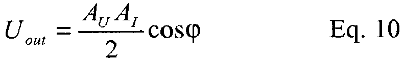
- In case of an "ideal" inductance the coil voltage leads the coil current by φ=90°. In this "ideal" case the output signal Uout is zero because of cos(90°)=0. Because of the inductive coupling of
coil L 51 and electrical conducting tissue (not shown inFig. 7 ), the phase angle φ is decreased and the output signal Uout is not zero. In other words, the blood pulse within an artery, representing a blood volume with varying throughput, passing thecoil L 51, modulates the amplitude of the output signal Uout. - In practical operation no pure inductive
measuring coil L 51 is obtained. Because of thecoil supply lines 60, there are parasitic couplings, seeFig. 8 . These couplings are small, however, resulting in a capacitory effect. The combination of measuringcoil L 81 and parallel connected parasitic capacitor form a resonant circuit. Typically, the self-resonant frequency of such ameasuring coil L 81 is some MHz. In other words, the self-resonant angular frequency is in the frequency range of the measuring angular frequency ω. - The electromagnetic coupling to the passing pulse wave attenuates the resonance amplitude and detunes the resonance frequency of the measuring setup. These effects can be used for pulse detection as well.
- A way of operating a single coil setup at the self-resonant frequency of the coil is described below. For this purpose a closed
loop control circuit 101 is used. Instead of an AC supply point UAC a voltage-controlledoscillator 82 with variable frequency is used. Theoscillator 82 feeds a parallel resonant circuit, which is formed by the measuringcoil L 81 and the parasitic capacity (supply lines 60). InFig. 8 basic buffer amplifier - In the closed loop control circuit illustrated in
Fig. 8 an "error" voltage e is provided as resulting signal ofmixer 85 and low-pass filter 86. The aim is to adjust this error value e to zero. In contrast to the embodiment illustrated inFig. 7 , in which the resulting voltage ofmixer 55 and low-pass filter 56 changes to zero if coil voltage and coil current show a phase angel of 90°, in the embodiment illustrated inFig. 8 an additional 90°phase shifter 87 is employed in a way that voltage e equals zero if voltage and current of thecoil L 81 are in phase (phase angle=0°). In an oscillating circuit this is the case if the operating frequency equals the resonance frequency. As long as the error voltage e is not zero, thePI controller 88 receiving the error voltage e regulates its output voltage Uout such that its input voltage becomes zero (e=0). In other words, thePI controller 88 uses the error voltage e to generate a control voltage Ucontrol for the voltage controlledoscillator 82. Theoscillator 82 is controlled until the error voltage e equals zero, i.e. the present resonance frequency is reached. - Instead of a PI controller 88 (proportional integral controller) a P controller (proportional controller) can be used. In this case the error voltage e can be adjusted to a minimum only, the value of which depends on the amplification factor of the P controller. A PI controller with integral part however integrates lowest error voltages e. Other controllers known in the state of the art can also be used.
- An output value of the illustrated setup is the control voltage Ucontrol of the
oscillator 82. If the resonance frequency changes because of a pulse wave passing thecoil L 81, the control loop control circuit tunes theoscillator 82 accordingly, and the control voltage Ucontrol of theoscillator 82 changes. -
Fig. 9 illustrates a typical current-frequency dependency in a single coil embodiment (parallel oscillating circuit) in case of ϕ= 0° (resonance frequency fl). In case of resonance the phase angle is zero, i.e. voltage and current are in phase. In other words, current I consists of the part Iinphase only. As a second output value in case of resonance the signal XI can be used, as illustrated inFig. 8 . Signal XI corresponds to the amplitude of the resonance curve, representing the attenuation of the oscillating circuit. If the attenuation of the oscillating circuit is high, e.g. due to electrical conductive material, like blood, the resonance curve shows a low amplitude. - The setup as illustrated in
Fig. 8 allows the determination of the present resonance frequency and the determination of the attenuation of the oscillating circuit, both values depending on the presence of electrical conducting material (e.g. a passing pulse wave) close to the measuringcoil L 81. - In another embodiment a measurement setup is used, which in particular is of advantage in case of very high measuring sensitivity. Again the setup is built as a closed
loop control circuit 102, in which theoscillator 92 is controlled such, that instead of a resonance a certain point on the edge of theresonance curve 200 is reached. This certain point is defined such that the part Iinphase of current in phase with the coil voltage is equal in size to the part Iquadrature of current, which shows a phase angel of 90° to the coil voltage, as illustrated inFig. 10 . A typical current-frequency dependency in a single coil embodiment (parallel oscillating circuit) in case of ϕ=45° (frequency f2) is shown. - The closed
loop control circuit 102 used in this embodiment is adapted in a way that the difference between Iinphase and Iquadrature is used as the error value to be minimized. If both parts of current show the same size, the difference equals zero. InFig. 11 a setup is shown for operating on the edge of theresonance curve 200. In this embodiment the setups as shown inFig. 7 and 8 are combined. Afirst mixer 95a determines the components of the coil current, which are in phase with the coil voltage, as known fromFig. 7 . Asecond mixer 95b determines the component of the coil current, which show a 90° phase shift to the coil voltage, as known fromFig. 8 . Both components are subtracted from each other and the resulting value is fed to thePI controller 98 as an error value. ThePI controller 98 generates the control voltage for the voltage controlled oscillator. ThePI controller 98 regulates its output voltage Uout such that its input voltage becomes zero (e=0). - In contrast to the embodiments described above, additionally a sample & hold
element 99 is employed. The sample & holdelement 99 is located between thePI controller 98 and the voltage controlledoscillator 92 and serves as a closed switch, if the sample & holdelement 99 operates in "sample" mode. In other words, the output voltage Ucontrol of thePI controller 98 is given to the control input of theoscillator 92. If the sample & holdelement 99 operates in "hold" mode, the sample & holdelement 99 interrupts the direct connection between thePI controller 98 and theoscillator 92. At the same time the sample & holdelement 99 provides ("holds") on its output the last valid voltage value. - In other words, in the "sample" mode the closed loop of the
control circuit 102 will be closed and the inflection point on the edge of thefrequency curve 200 will be used as operating frequency, and in the "hold" mode the closed loop of thecontrol circuit 102 will be opened in a way that theoscillator 92 oscillates with the last setup frequency. - In order to carry out a measurement the
oscillator 92 is set up on the inflection point of the edge of thepresent frequency curve 200 using the "sample" mode. In a next step the sample & holdelement 99 is switched to the "hold" mode. Because the inflection point is the steepest point on the edge of theresonance curve 200, a small shift of the coil's natural resonance, e.g. due to a passing pulse wave, results in a large effect on the amplitude of the coil current to be measured. In order to detect a passing pulse wave, the voltage XI is measured, which represents the coil current. - In practice there is a periodical switching between the "sample" mode and the "hold" mode, in order to provide a quasi-continuous measurement, during which the readjusting during the "sample" mode is done within some milliseconds. An example of such a switching between "sample" mode and "hold" mode illustrates
Fig. 12 . - In "sample" mode slow changes of the environment, e.g. a changing coupling of the measuring coil to the part of the subject's body which is used for pulse detection, would be compensated, whereas fast measuring effects, e.g. caused by a passing pulse wave, would be acquired in a quasi-continuous way during the "hold" mode.
- In order to control the different modes of operation, a preferred control strategy is to provide a short switch from the "hold" mode to the "sample" mode only in case of a significant deviation of the coupling behaviour due to a changing measuring environment. Such a deviation is determined by observing the output of the
PI controller 98. In "hold" mode thePI controller 98 verifies the error value, i.e. the difference between Iinphase and Iquadrature. As long as this difference is below a certain threshold, the measurement is "on edge". The threshold has to be set high enough, such that the short peaks of the error value caused by passing pulse waves do not lead to a switch to the "sample" mode. - In a single coil setup, as described above, the electrical coil parameters change due to neighbouring electrical conductive material, e.g. a pulse wave. A change of coil parameters is detected by measuring of coil voltage and coil current and by determining the phase difference.
- A measurement system with dual coil setup is illustrated in
Fig. 3 . In this setup the coupling between twoseparate coils coils coil L m 21 is zero due to the symmetry of the coil arrangement, i.e. no voltage is induced in the receivingcoil L m 21. If an electrically conductive material is in the neighbourhood of the coils the magnetic field of thefield coil L e 20 is distorted and the net flux through the receivingcoil L m 21 does not equal zero. In other words, a voltage is induced. - In contrast to the single coil setup, the aim of the measuring setup is not to examine the phase difference of two signals. Instead, a very small signal in a very "noisy" environment has to be measured. A known method for such a measurement is the so called lock-in method. In
Fig. 13 a setup for acontrol circuit 103 is shown, in which a lock-inamplifier 110 is used to evaluate the signals of the dual coil setup. - The lock-in
amplifier 110 comprises two signal input channels. The first input channel (reference input) 111 is used for a reference signal and the second input channel (measuring input) 112 is used for a measuring signal. As reference signal the alternating voltage UAC of thefield coil L e 20 is used. The measuring signal is the voltage which is induced in the receivingcoil L m 21. - Without any coupling between the two
coils coils coil L m 21. This alternating voltage exhibits the same frequency as UAC. Amplitude and phase of the voltage depend on the coupling between the twocoils - In order to compensate the phase shift between reference signal and measuring signal, the lock-in
amplifier 110 comprises anadjustable phase shifter 113, which is adapted in a way that to themixer 115 both signals are provided with the same phasing. In this way, a maximal output voltage Uout can be obtained after the low-pass filter 118, which is provided after themixer 115.
- Eq. 14 is equivalent to Eq. 13, which is maximal for ϕ=0°. An advantage of the lock-in technique is that interfering frequencies and noise exhibiting undefined or changing phasing with regard to the reference signal averages to zero after the
mixer 115. In theamplifier 110 the reference signal passes abuffer 116 in order to reach thephase shifter 113 and the measuring signal passes abuffer 117 and a band-pass filter 114 in order to reach themixer 115. -
Figs. 14 and 15 illustrate two different embodiments of a non-invasive mobile measuring system comprising a sensor as described above. The measuring system comprises awristband 310 or bracelet or the like, into which the sensor coil(s) 320, 330 are integrated together with the circuitry and a power supply, e.g. a small battery. In addition a display (not shown) can be provided for displaying heart rate or other physiological parameters to the user. In a first embodiment a larger single coil is arranged in a way that it embraces the user's wrist 300 (Fig. 14 ). In a second embodiment a smallsingle coil 320 is arranged on the exterior of the subject's body, at a certain place of the user'swrist 300, surrounding a spot of some centimeter in diameter (Fig. 15 ). - Instead of a wristworn device, other devices can be provided to wear the measuring device at different parts of the body, e.g. on the chest, the waist, the ankle etc. Two or more of such devices can be worn simultaneously in order to provide a BP measurement or a multiple parameter measurement. Alternatively, the measuring system according to the present invention can be adapted to be part of a garment or another piece of clothing, e.g. an underwear etc.
- The measuring device preferably comprises a built-in analysing unit, comprising a microprocessor or the like in order to execute an analysing software. The analysing software is adapted to determine, based on the detected pulse waves, PTT and/or PWV values. Furthermore the analyzing software is adapted to determine BP values of the subject wearing the measuring device. Depending on the number of sensors used and the sensing positions, different vital parameters can be determined, e.g. heart rate, respiration rate etc.
- All appliances described above are adapted to carry out the method according to the present invention. All
circuitry - It will be evident to those skilled in the art that the invention is not limited to the details of the foregoing illustrative embodiments, and that the present invention may be embodied in other specific forms. The present embodiments are therefore to be considered in all respects as illustrative and not restrictive, the scope of the invention being indicated by the appended claims rather than by the foregoing description, and all changes which come within the meaning and range of equivalency of the claims are therefore intended to be embraced therein. It will furthermore be evident that the word "comprising" does not exclude other elements or steps, that the words "a" or "an" do not exclude a plurality, and that a single element, such as a computer system or another unit may fulfil the functions of several means recited in the claims. Any reference signs in the claims shall not be construed as limiting the claim concerned.
-
- 10
- measuring coil
- 11
- tissue
- 12
- primary circuit
- 13
- body circuit
- 20
- field coil
- 21
- measuring coil
- 22
- artery
- 23
- direction of blood flow
- 30
- curve
- 31
- curve
- 40
- voltage difference
- 50
- supply point
- 51
- measuring coil
- 52
- resistor
- 53
- differential amplifier
- 54
- differential amplifier
- 55
- mixer
- 56
- low-pass filter
- 60
- supply line
- 81
- measuring coil
- 82
- oscillator
- 83
- amplifier
- 84
- amplifier
- 85
- mixer
- 86
- low-pass filter
- 87
- phase shifter
- 88
- PI controller
- 92
- oscillator
- 93
- buffer
- 94
- buffer
- 95
- mixer
- 96
- low-pass filter
- 97
- phase shifter
- 98
- controller
- 99
- sample & hold element
- 100
- control circuit
- 101
- control circuit
- 102
- control circuit
- 103
- control circuit
- 110
- lock-in amplifier
- 111
- input channel/reference channel
- 112
- input channel/measurement channel
- 113
- phase shifter
- 114
- band-pass filter
- 115
- mixer
- 116
- buffer
- 117
- buffer
- 118
- low-pass filter
- 200
- resonance curve
- 300
- wrist
- 310
- wristband
- 320
- measuring coil
- 330
- measuring coil
Claims (9)
- A sensor for detecting the passing of a pulse wave from a subject's arterial system (22), the sensor being adapted to be located at a sensing position on the exterior of the subject's body, wherein the sensor comprises:- a number of electrical coils (20, 21, 21') for generating an inductive coupling to the subject's body in a way that the properties of said inductive coupling change if a pulse wave passes a screened volume underneath the sensing position, and- a circuit (100, 101, 102, 103) connected to the number of electrical coils, said circuit being adapted to detect said property changes of the inductive coupling, characterised in that the number of electrical coils comprises a field coil (20) for producing a primary magnetic field and at least one receiving coil (21,21') for screening the primary magnetic field, the axis of the at least one receiving coil being perpendicular to the axis of the field coil.
- The sensor as claimed in claim 1, characterized in that the at least one receiving coil (21, 21') comprises a single electrical coil, the electrical properties of which being changed, if a pulse wave passes the sensing position.
- The sensor as claimed in claim 1, characterized in that the at least one receiving coil (21, 21') comprises two separate electrical coils, the electrical properties of which being changed, if a pulse wave passes the sensing position.
- A non-invasive measuring system, being adapted to be attached to the exterior of the subject's body, characterized in that it comprises one sensor as claimed in claim 1, the system being adapted to provide information about the heart rate of the subject.
- A non-invasive measuring system, being adapted to be attached to the exterior of the subject's body, comprising two sensors as claimed in claim 1, the sensing positions of said sensors being spaced apart, the system being adapted to provide information about the blood pressure of the subject.
- Method for detecting the passing of a pulse wave from a subject's arterial system (22), the method comprising the steps of:- generating an inductive coupling between a number of electrical coils (20, 21,21') and the subject's body in a way that the properties of said inductive coupling change if a pulse passes a screened volume underneath the sensing position, wherein the number of electrical coils comprises a field coil (20) producing a primary magnetic field and at least one receiving coil (21, 21') for screening the primary magnetic field, the axis of the at least one receiving coil (20) being perpendicular to the axis of the field coil (21, 21'); and- detecting said property changes of the inductive coupling.
- Method for determining the heart rate of a subject, the method comprising the steps of:- detecting the passing of at least two successive pulse waves using the method as claimed in claim 6,- measuring the time interval between said pulse waves, and determining the heart rate.
- Method for determining the blood pressure of a subject, the method comprising the steps of:- detecting the passing of a pulse wave at two spaced apart sensing locations using the method as claimed in claim 6,- measuring the pulse transit time between said sensing locations, and determining the blood pressure.
- A computer program for detecting the passing of a pulse wave from a subject's arterial system using the method disclosed in claim 6, during which an inductive coupling between a number of electrical coils (20, 21,21') and the subject's body in generated in a way that the properties of said inductive coupling change if a pulse passes a screened volume underneath the sensing position, wherein the number of electrical coils comprises a field coil (20) for producing a primary magnetic field and at least one receiving coil (21,21') for screening the primary magnetic field, the axis of the at least one receiving coil (21, 21') being perpendicular to the axis of the field coil (20); the program comprising computer instructions to detect said property changes of the inductive coupling, when the computer program is executed in a computer.
Priority Applications (1)
| Application Number | Priority Date | Filing Date | Title |
|---|---|---|---|
| EP07805114.1A EP2049012B1 (en) | 2006-08-02 | 2007-07-11 | Sensor for detecting the passing of a pulse wave from a subject´s arterial system |
Applications Claiming Priority (3)
| Application Number | Priority Date | Filing Date | Title |
|---|---|---|---|
| EP06118316 | 2006-08-02 | ||
| PCT/IB2007/052763 WO2008015598A2 (en) | 2006-08-02 | 2007-07-11 | Sensor for detecting the passing of a pulse wave from a subject´s arterial system |
| EP07805114.1A EP2049012B1 (en) | 2006-08-02 | 2007-07-11 | Sensor for detecting the passing of a pulse wave from a subject´s arterial system |
Publications (2)
| Publication Number | Publication Date |
|---|---|
| EP2049012A2 EP2049012A2 (en) | 2009-04-22 |
| EP2049012B1 true EP2049012B1 (en) | 2015-04-15 |
Family
ID=38910897
Family Applications (1)
| Application Number | Title | Priority Date | Filing Date |
|---|---|---|---|
| EP07805114.1A Active EP2049012B1 (en) | 2006-08-02 | 2007-07-11 | Sensor for detecting the passing of a pulse wave from a subject´s arterial system |
Country Status (5)
| Country | Link |
|---|---|
| US (1) | US20090306524A1 (en) |
| EP (1) | EP2049012B1 (en) |
| JP (1) | JP2009545356A (en) |
| CN (1) | CN101495034B (en) |
| WO (1) | WO2008015598A2 (en) |
Families Citing this family (55)
| Publication number | Priority date | Publication date | Assignee | Title |
|---|---|---|---|---|
| US11330988B2 (en) | 2007-06-12 | 2022-05-17 | Sotera Wireless, Inc. | Body-worn system for measuring continuous non-invasive blood pressure (cNIBP) |
| US11607152B2 (en) | 2007-06-12 | 2023-03-21 | Sotera Wireless, Inc. | Optical sensors for use in vital sign monitoring |
| US8602997B2 (en) | 2007-06-12 | 2013-12-10 | Sotera Wireless, Inc. | Body-worn system for measuring continuous non-invasive blood pressure (cNIBP) |
| US8554297B2 (en) | 2009-06-17 | 2013-10-08 | Sotera Wireless, Inc. | Body-worn pulse oximeter |
| WO2008154643A1 (en) | 2007-06-12 | 2008-12-18 | Triage Wireless, Inc. | Vital sign monitor for measuring blood pressure using optical, electrical, and pressure waveforms |
| US8738118B2 (en) | 2009-05-20 | 2014-05-27 | Sotera Wireless, Inc. | Cable system for generating signals for detecting motion and measuring vital signs |
| US8180440B2 (en) | 2009-05-20 | 2012-05-15 | Sotera Wireless, Inc. | Alarm system that processes both motion and vital signs using specific heuristic rules and thresholds |
| US11896350B2 (en) | 2009-05-20 | 2024-02-13 | Sotera Wireless, Inc. | Cable system for generating signals for detecting motion and measuring vital signs |
| US11253169B2 (en) | 2009-09-14 | 2022-02-22 | Sotera Wireless, Inc. | Body-worn monitor for measuring respiration rate |
| US8545417B2 (en) | 2009-09-14 | 2013-10-01 | Sotera Wireless, Inc. | Body-worn monitor for measuring respiration rate |
| US8364250B2 (en) | 2009-09-15 | 2013-01-29 | Sotera Wireless, Inc. | Body-worn vital sign monitor |
| US8527038B2 (en) | 2009-09-15 | 2013-09-03 | Sotera Wireless, Inc. | Body-worn vital sign monitor |
| US8321004B2 (en) | 2009-09-15 | 2012-11-27 | Sotera Wireless, Inc. | Body-worn vital sign monitor |
| US10806351B2 (en) | 2009-09-15 | 2020-10-20 | Sotera Wireless, Inc. | Body-worn vital sign monitor |
| US20110066044A1 (en) | 2009-09-15 | 2011-03-17 | Jim Moon | Body-worn vital sign monitor |
| US10420476B2 (en) | 2009-09-15 | 2019-09-24 | Sotera Wireless, Inc. | Body-worn vital sign monitor |
| US8591411B2 (en) | 2010-03-10 | 2013-11-26 | Sotera Wireless, Inc. | Body-worn vital sign monitor |
| US9173594B2 (en) | 2010-04-19 | 2015-11-03 | Sotera Wireless, Inc. | Body-worn monitor for measuring respiratory rate |
| US9173593B2 (en) | 2010-04-19 | 2015-11-03 | Sotera Wireless, Inc. | Body-worn monitor for measuring respiratory rate |
| US8979765B2 (en) | 2010-04-19 | 2015-03-17 | Sotera Wireless, Inc. | Body-worn monitor for measuring respiratory rate |
| US8888700B2 (en) | 2010-04-19 | 2014-11-18 | Sotera Wireless, Inc. | Body-worn monitor for measuring respiratory rate |
| US9339209B2 (en) | 2010-04-19 | 2016-05-17 | Sotera Wireless, Inc. | Body-worn monitor for measuring respiratory rate |
| US8747330B2 (en) | 2010-04-19 | 2014-06-10 | Sotera Wireless, Inc. | Body-worn monitor for measuring respiratory rate |
| CN102003973B (en) * | 2010-10-19 | 2013-01-23 | 首都医科大学 | Wireless passive measuring method and circuit |
| KR101239348B1 (en) * | 2010-11-04 | 2013-03-06 | 김희곤 | Portable pulse measuring device |
| US20140249432A1 (en) | 2010-12-28 | 2014-09-04 | Matt Banet | Body-worn system for continuous, noninvasive measurement of cardiac output, stroke volume, cardiac power, and blood pressure |
| SG192836A1 (en) | 2011-02-18 | 2013-09-30 | Sotera Wireless Inc | Modular wrist-worn processor for patient monitoring |
| WO2012112885A1 (en) | 2011-02-18 | 2012-08-23 | Sotera Wireless, Inc. | Optical sensor for measuring physiological properties |
| GB201112477D0 (en) * | 2011-07-20 | 2011-08-31 | Corentium As | Gas sensor |
| US9814395B2 (en) | 2011-08-10 | 2017-11-14 | Cardiac Pacemakers, Inc. | Method and apparatus for determination of physiological parameters using cervical impedance |
| US20130158417A1 (en) * | 2011-12-16 | 2013-06-20 | General Electric Company | Method, apparatus and computer program for automatic non-invasive blood pressure measurement |
| US9247896B2 (en) | 2012-01-04 | 2016-02-02 | Nellcor Puritan Bennett Ireland | Systems and methods for determining respiration information using phase locked loop |
| CN103054571B (en) * | 2012-12-12 | 2014-10-15 | 重庆大学 | Portable electrocardio and sleep respiration monitoring system |
| ITMI20130104A1 (en) * | 2013-01-24 | 2014-07-25 | Empatica Srl | DEVICE, SYSTEM AND METHOD FOR THE DETECTION AND TREATMENT OF HEART SIGNALS |
| US9560978B2 (en) | 2013-02-05 | 2017-02-07 | Covidien Lp | Systems and methods for determining respiration information from a physiological signal using amplitude demodulation |
| US9554712B2 (en) | 2013-02-27 | 2017-01-31 | Covidien Lp | Systems and methods for generating an artificial photoplethysmograph signal |
| US9364182B2 (en) * | 2013-03-18 | 2016-06-14 | Maisense Inc. | Pulse measurement devices for bio-signals |
| CN104414626B (en) * | 2013-08-23 | 2016-12-28 | 同方健康科技(北京)股份有限公司 | The method that electronics magnetic induction sphygomanometer is carried out parameter calibration |
| CN103584847B (en) * | 2013-11-06 | 2015-04-22 | 中国人民解放军第三军医大学 | Non-contact magnetic induction heart rate and respiration rate synchronous detection method and system |
| CN106535750A (en) * | 2014-07-14 | 2017-03-22 | 森斯弗里有限公司 | Systems and methods for contactless arterial pressure estimator |
| WO2016065476A1 (en) * | 2014-10-30 | 2016-05-06 | 2352409 Ontario Inc. | A wearable device and method for non-invasive monitoring continuous blood pressure and other physiological parameters with reduced movement artifacts |
| KR101644586B1 (en) * | 2014-11-18 | 2016-08-02 | 상명대학교서울산학협력단 | Method and system for detecmining social relationship using Heart Rhythm Pattern by micro movement of body |
| TW201624445A (en) * | 2014-12-25 | 2016-07-01 | 中華映管股份有限公司 | Method for adjusting terminal impedance |
| US10548495B2 (en) * | 2015-04-01 | 2020-02-04 | Xtrava Inc. | Contactless or non-invasive physical properties measurement instrument using eddy current-reduced high Q resonant circuit probe |
| EP3337393B1 (en) * | 2015-08-21 | 2021-03-10 | Koninklijke Philips N.V. | Monitoring apparatus for monitoring blood pressure of a subject |
| CN107923930B (en) * | 2015-09-02 | 2020-07-10 | 德克萨斯仪器股份有限公司 | Inductive sensing with differential inductance readout based on sense/reference L C ring oscillator with shared capacitor |
| CN105286919B (en) * | 2015-10-13 | 2018-06-22 | 广州丰谱信息技术有限公司 | Blood vessel state detection method and device based on heart point fluctuation transport properties |
| JP6597410B2 (en) * | 2016-03-04 | 2019-10-30 | セイコーエプソン株式会社 | Biological information measuring device and biological information measuring method |
| WO2017162616A1 (en) | 2016-03-23 | 2017-09-28 | Koninklijke Philips N.V. | Blood pressure monitor |
| WO2018019648A1 (en) * | 2016-07-27 | 2018-02-01 | Koninklijke Philips N.V. | Monitoring device for monitoring a physiological characteristic of a subject |
| US10641734B2 (en) * | 2016-08-28 | 2020-05-05 | Xtrava Inc. | Micro powered ultra-high resolution electromagnetic sensor with real time analog circuitry based artifact cancellation |
| US10874305B2 (en) * | 2018-01-15 | 2020-12-29 | Microsoft Technology Licensing, Llc | Sensor device |
| EP3620109A1 (en) | 2018-09-04 | 2020-03-11 | Koninklijke Philips N.V. | Inductive sensing device and method |
| CN112263222A (en) * | 2020-11-13 | 2021-01-26 | 电子科技大学 | Feedback enhanced pulse condition searching and collecting array and method |
| KR20230087737A (en) * | 2021-12-10 | 2023-06-19 | 조현경 | Blood pressure waveform measuring sensor and blood pressure measuring device |
Citations (1)
| Publication number | Priority date | Publication date | Assignee | Title |
|---|---|---|---|---|
| US3980076A (en) * | 1974-10-02 | 1976-09-14 | The Board Of Trustees Of Leland Stanford Junior University | Method for measuring externally of the human body magnetic susceptibility changes |
Family Cites Families (26)
| Publication number | Priority date | Publication date | Assignee | Title |
|---|---|---|---|---|
| US2368036A (en) * | 1942-12-04 | 1945-01-23 | O'brien Elwin James | Coupled circuit frequency modulator |
| US3260109A (en) * | 1962-04-24 | 1966-07-12 | Fischer & Porter Co | Electromagnetic flowmeter measuring apparatus |
| FR1383169A (en) * | 1963-11-15 | 1964-12-24 | Schlumberger Prospection | Improvements to flowmeters |
| US3560845A (en) * | 1965-05-03 | 1971-02-02 | Harold D Goldberg | Measuring devices |
| JPS5212387Y2 (en) * | 1972-03-06 | 1977-03-18 | ||
| JPS5129973A (en) * | 1974-09-06 | 1976-03-13 | Hajime Yamada | KADENRYUSHI KISOKU DOKEI |
| US4425920A (en) * | 1980-10-24 | 1984-01-17 | Purdue Research Foundation | Apparatus and method for measurement and control of blood pressure |
| US4452252A (en) * | 1981-05-26 | 1984-06-05 | Respitrace Corporation | Non-invasive method for monitoring cardiopulmonary parameters |
| US4548211A (en) * | 1984-01-12 | 1985-10-22 | Marks Lloyd A | Computer assisted admittance plethysmograph |
| DE59107232D1 (en) * | 1990-07-18 | 1996-02-22 | Avl Medical Instr Ag | Device and method for measuring blood pressure |
| US5642734A (en) * | 1990-10-04 | 1997-07-01 | Microcor, Inc. | Method and apparatus for noninvasively determining hematocrit |
| US5590649A (en) * | 1994-04-15 | 1997-01-07 | Vital Insite, Inc. | Apparatus and method for measuring an induced perturbation to determine blood pressure |
| JP3318727B2 (en) * | 1994-06-06 | 2002-08-26 | 日本光電工業株式会社 | Pulse wave transit time sphygmomanometer |
| JPH10104038A (en) * | 1996-09-27 | 1998-04-24 | Nkk Corp | Method and apparatus for measurement of flow velocity |
| US5844144A (en) * | 1997-03-04 | 1998-12-01 | Jennings; Gordon H. | Method for estimating flow velocity |
| US6491647B1 (en) * | 1998-09-23 | 2002-12-10 | Active Signal Technologies, Inc. | Physiological sensing device |
| JP2001112725A (en) * | 1999-10-15 | 2001-04-24 | Dia Syst Kk | Biological information measuring apparatus |
| AU2001221391A1 (en) * | 2000-01-26 | 2001-08-07 | Vsm Medtech Ltd. | Continuous blood pressure monitoring method and apparatus |
| EP2324761A3 (en) * | 2000-04-17 | 2014-06-18 | Adidas AG | Systems and methods for ambulatory monitoring of physiological signals |
| US6475153B1 (en) * | 2000-05-10 | 2002-11-05 | Motorola Inc. | Method for obtaining blood pressure data from optical sensor |
| JP2002051997A (en) * | 2000-08-09 | 2002-02-19 | Nippon Colin Co Ltd | Heart sound analyzer |
| US6803757B2 (en) * | 2001-10-02 | 2004-10-12 | Bentley Nevada, Llc | Multi-coil eddy current proximity probe system |
| US6648828B2 (en) * | 2002-03-01 | 2003-11-18 | Ge Medical Systems Information Technologies, Inc. | Continuous, non-invasive technique for measuring blood pressure using impedance plethysmography |
| JP2003275183A (en) | 2002-03-25 | 2003-09-30 | Matsushita Electric Ind Co Ltd | Biological information detection sensor and sensor control device |
| US6575044B1 (en) * | 2002-05-06 | 2003-06-10 | Murray F. Feller | Transit-time flow sensor combining high resolution and wide dynamic range |
| JP2008513152A (en) * | 2004-09-21 | 2008-05-01 | ヴィーヴォメトリックス インコーポレイテッド | Improved sensor for inductive plethysmograph monitoring applications and apparel using it |
-
2007
- 2007-07-11 EP EP07805114.1A patent/EP2049012B1/en active Active
- 2007-07-11 WO PCT/IB2007/052763 patent/WO2008015598A2/en active Application Filing
- 2007-07-11 US US12/375,579 patent/US20090306524A1/en not_active Abandoned
- 2007-07-11 JP JP2009522377A patent/JP2009545356A/en active Pending
- 2007-07-11 CN CN200780028530.5A patent/CN101495034B/en active Active
Patent Citations (1)
| Publication number | Priority date | Publication date | Assignee | Title |
|---|---|---|---|---|
| US3980076A (en) * | 1974-10-02 | 1976-09-14 | The Board Of Trustees Of Leland Stanford Junior University | Method for measuring externally of the human body magnetic susceptibility changes |
Non-Patent Citations (1)
| Title |
|---|
| "ORTHOGONAL-COILS RECEIVER: A CONFIGURATION FOR IMPROVING THE POSITION TOLERANCE OF COUPLED MORPHOGNOSTIC COILS", MEDICAL AND BIOLOGICAL ENGINEERING AND COMPUTING, vol. 21, no. 2, 1 March 1983 (1983-03-01), SPRINGER, HEILDELBERG, DE, pages 224 - 226, XP009008216, ISSN: 0140-0118 * |
Also Published As
| Publication number | Publication date |
|---|---|
| US20090306524A1 (en) | 2009-12-10 |
| WO2008015598A2 (en) | 2008-02-07 |
| CN101495034B (en) | 2013-01-02 |
| WO2008015598A3 (en) | 2008-05-02 |
| EP2049012A2 (en) | 2009-04-22 |
| JP2009545356A (en) | 2009-12-24 |
| CN101495034A (en) | 2009-07-29 |
Similar Documents
| Publication | Publication Date | Title |
|---|---|---|
| EP2049012B1 (en) | Sensor for detecting the passing of a pulse wave from a subject´s arterial system | |
| Huynh et al. | Noninvasive cuffless blood pressure estimation using pulse transit time and impedance plethysmography | |
| JP6321090B2 (en) | Method and system for determining cardiovascular volume in a mammal | |
| US9808168B2 (en) | Method and system for non-invasive measurement of cardiac parameters | |
| Summers et al. | Bench to bedside: electrophysiologic and clinical principles of noninvasive hemodynamic monitoring using impedance cardiography | |
| CN102008296B (en) | Device and method for measuring arterial blood pressures based on pulse wave signals and electrocardiosignals | |
| US6893400B2 (en) | Angiopathy diagnosing apparatus | |
| US20200000349A1 (en) | Pulse detection module and use-as-you-need blood pressure measurement device comprising the same | |
| WO2000074563A1 (en) | Method and device for arterial blood pressure measurement | |
| JP2001500392A (en) | Method and device for non-invasively measuring hematocrit | |
| Tamura | Cuffless blood pressure monitors: Principles, standards and approval for medical use | |
| US9345436B2 (en) | Apparatus and methods for computing cardiac output of a living subject | |
| EP3856014A1 (en) | Model-based sensor technology for detection of cardiovascular status | |
| JP3637916B2 (en) | Biological condition measuring device | |
| Dosinas et al. | Measurement of human physiological parameters in the systems of active clothing and wearable technologies | |
| Sharman et al. | Measurements of arterial pressure and flow in vivo | |
| JP2020069249A (en) | Health management device and health management method | |
| Koohi | Methods for Non-invasive trustworthy estimation of arterial blood pressure | |
| CN107708534A (en) | Blood pressure measuring device | |
| Sokolsky et al. | Innovative Mobile Device for Human Health Monitoring | |
| WO2003103488A2 (en) | Method of non-invasive estimation of the hemodynamic parameters in aortic arch |
Legal Events
| Date | Code | Title | Description |
|---|---|---|---|
| PUAI | Public reference made under article 153(3) epc to a published international application that has entered the european phase |
Free format text: ORIGINAL CODE: 0009012 |
|
| 17P | Request for examination filed |
Effective date: 20090302 |
|
| AK | Designated contracting states |
Kind code of ref document: A2 Designated state(s): AT BE BG CH CY CZ DE DK EE ES FI FR GB GR HU IE IS IT LI LT LU LV MC MT NL PL PT RO SE SI SK TR |
|
| AX | Request for extension of the european patent |
Extension state: AL BA HR MK RS |
|
| DAX | Request for extension of the european patent (deleted) | ||
| 17Q | First examination report despatched |
Effective date: 20110711 |
|
| RAP1 | Party data changed (applicant data changed or rights of an application transferred) |
Owner name: PHILIPS INTELLECTUAL PROPERTY & STANDARDS GMBH Owner name: KONINKLIJKE PHILIPS N.V. |
|
| REG | Reference to a national code |
Ref country code: DE Ref legal event code: R079 Ref document number: 602007041079 Country of ref document: DE Free format text: PREVIOUS MAIN CLASS: A61B0005020000 Ipc: A61B0005021000 |
|
| GRAP | Despatch of communication of intention to grant a patent |
Free format text: ORIGINAL CODE: EPIDOSNIGR1 |
|
| RIC1 | Information provided on ipc code assigned before grant |
Ipc: A61B 5/021 20060101AFI20141023BHEP Ipc: A61B 5/053 20060101ALI20141023BHEP |
|
| RIN1 | Information on inventor provided before grant (corrected) |
Inventor name: MUEHLSTEFF, JENS Inventor name: THIJS, JEROEN ADRIANUS JOHANNES Inventor name: IGNEY, CLAUDIA HANNELORE Inventor name: PINTER, ROBERT |
|
| INTG | Intention to grant announced |
Effective date: 20141124 |
|
| GRAS | Grant fee paid |
Free format text: ORIGINAL CODE: EPIDOSNIGR3 |
|
| GRAA | (expected) grant |
Free format text: ORIGINAL CODE: 0009210 |
|
| AK | Designated contracting states |
Kind code of ref document: B1 Designated state(s): AT BE BG CH CY CZ DE DK EE ES FI FR GB GR HU IE IS IT LI LT LU LV MC MT NL PL PT RO SE SI SK TR |
|
| REG | Reference to a national code |
Ref country code: GB Ref legal event code: FG4D Ref country code: CH Ref legal event code: EP |
|
| REG | Reference to a national code |
Ref country code: IE Ref legal event code: FG4D |
|
| REG | Reference to a national code |
Ref country code: AT Ref legal event code: REF Ref document number: 721479 Country of ref document: AT Kind code of ref document: T Effective date: 20150515 |
|
| REG | Reference to a national code |
Ref country code: DE Ref legal event code: R096 Ref document number: 602007041079 Country of ref document: DE Effective date: 20150528 |
|
| REG | Reference to a national code |
Ref country code: DE Ref legal event code: R082 Ref document number: 602007041079 Country of ref document: DE Representative=s name: MEISSNER, BOLTE & PARTNER GBR, DE Ref country code: DE Ref legal event code: R081 Ref document number: 602007041079 Country of ref document: DE Owner name: PHILIPS GMBH, DE Free format text: FORMER OWNER: PHILIPS INTELLECTUAL PROPERTY & STANDARDS GMBH, 20099 HAMBURG, DE Ref country code: DE Ref legal event code: R082 Ref document number: 602007041079 Country of ref document: DE Representative=s name: MEISSNER BOLTE PATENTANWAELTE RECHTSANWAELTE P, DE |
|
| REG | Reference to a national code |
Ref country code: NL Ref legal event code: VDEP Effective date: 20150415 |
|
| REG | Reference to a national code |
Ref country code: AT Ref legal event code: MK05 Ref document number: 721479 Country of ref document: AT Kind code of ref document: T Effective date: 20150415 |
|
| REG | Reference to a national code |
Ref country code: LT Ref legal event code: MG4D |
|
| PG25 | Lapsed in a contracting state [announced via postgrant information from national office to epo] |
Ref country code: NL Free format text: LAPSE BECAUSE OF FAILURE TO SUBMIT A TRANSLATION OF THE DESCRIPTION OR TO PAY THE FEE WITHIN THE PRESCRIBED TIME-LIMIT Effective date: 20150415 |
|
| PG25 | Lapsed in a contracting state [announced via postgrant information from national office to epo] |
Ref country code: FI Free format text: LAPSE BECAUSE OF FAILURE TO SUBMIT A TRANSLATION OF THE DESCRIPTION OR TO PAY THE FEE WITHIN THE PRESCRIBED TIME-LIMIT Effective date: 20150415 Ref country code: PT Free format text: LAPSE BECAUSE OF FAILURE TO SUBMIT A TRANSLATION OF THE DESCRIPTION OR TO PAY THE FEE WITHIN THE PRESCRIBED TIME-LIMIT Effective date: 20150817 Ref country code: LT Free format text: LAPSE BECAUSE OF FAILURE TO SUBMIT A TRANSLATION OF THE DESCRIPTION OR TO PAY THE FEE WITHIN THE PRESCRIBED TIME-LIMIT Effective date: 20150415 Ref country code: ES Free format text: LAPSE BECAUSE OF FAILURE TO SUBMIT A TRANSLATION OF THE DESCRIPTION OR TO PAY THE FEE WITHIN THE PRESCRIBED TIME-LIMIT Effective date: 20150415 |
|
| PG25 | Lapsed in a contracting state [announced via postgrant information from national office to epo] |
Ref country code: IS Free format text: LAPSE BECAUSE OF FAILURE TO SUBMIT A TRANSLATION OF THE DESCRIPTION OR TO PAY THE FEE WITHIN THE PRESCRIBED TIME-LIMIT Effective date: 20150815 Ref country code: AT Free format text: LAPSE BECAUSE OF FAILURE TO SUBMIT A TRANSLATION OF THE DESCRIPTION OR TO PAY THE FEE WITHIN THE PRESCRIBED TIME-LIMIT Effective date: 20150415 Ref country code: LV Free format text: LAPSE BECAUSE OF FAILURE TO SUBMIT A TRANSLATION OF THE DESCRIPTION OR TO PAY THE FEE WITHIN THE PRESCRIBED TIME-LIMIT Effective date: 20150415 Ref country code: GR Free format text: LAPSE BECAUSE OF FAILURE TO SUBMIT A TRANSLATION OF THE DESCRIPTION OR TO PAY THE FEE WITHIN THE PRESCRIBED TIME-LIMIT Effective date: 20150716 |
|
| REG | Reference to a national code |
Ref country code: DE Ref legal event code: R097 Ref document number: 602007041079 Country of ref document: DE |
|
| PG25 | Lapsed in a contracting state [announced via postgrant information from national office to epo] |
Ref country code: EE Free format text: LAPSE BECAUSE OF FAILURE TO SUBMIT A TRANSLATION OF THE DESCRIPTION OR TO PAY THE FEE WITHIN THE PRESCRIBED TIME-LIMIT Effective date: 20150415 Ref country code: DK Free format text: LAPSE BECAUSE OF FAILURE TO SUBMIT A TRANSLATION OF THE DESCRIPTION OR TO PAY THE FEE WITHIN THE PRESCRIBED TIME-LIMIT Effective date: 20150415 |
|
| PLBE | No opposition filed within time limit |
Free format text: ORIGINAL CODE: 0009261 |
|
| STAA | Information on the status of an ep patent application or granted ep patent |
Free format text: STATUS: NO OPPOSITION FILED WITHIN TIME LIMIT |
|
| PG25 | Lapsed in a contracting state [announced via postgrant information from national office to epo] |
Ref country code: PL Free format text: LAPSE BECAUSE OF FAILURE TO SUBMIT A TRANSLATION OF THE DESCRIPTION OR TO PAY THE FEE WITHIN THE PRESCRIBED TIME-LIMIT Effective date: 20150415 Ref country code: MC Free format text: LAPSE BECAUSE OF FAILURE TO SUBMIT A TRANSLATION OF THE DESCRIPTION OR TO PAY THE FEE WITHIN THE PRESCRIBED TIME-LIMIT Effective date: 20150415 Ref country code: CZ Free format text: LAPSE BECAUSE OF FAILURE TO SUBMIT A TRANSLATION OF THE DESCRIPTION OR TO PAY THE FEE WITHIN THE PRESCRIBED TIME-LIMIT Effective date: 20150415 Ref country code: RO Free format text: LAPSE BECAUSE OF NON-PAYMENT OF DUE FEES Effective date: 20150415 Ref country code: SK Free format text: LAPSE BECAUSE OF FAILURE TO SUBMIT A TRANSLATION OF THE DESCRIPTION OR TO PAY THE FEE WITHIN THE PRESCRIBED TIME-LIMIT Effective date: 20150415 |
|
| REG | Reference to a national code |
Ref country code: CH Ref legal event code: PL |
|
| 26N | No opposition filed |
Effective date: 20160118 |
|
| GBPC | Gb: european patent ceased through non-payment of renewal fee |
Effective date: 20150715 |
|
| PG25 | Lapsed in a contracting state [announced via postgrant information from national office to epo] |
Ref country code: LU Free format text: LAPSE BECAUSE OF FAILURE TO SUBMIT A TRANSLATION OF THE DESCRIPTION OR TO PAY THE FEE WITHIN THE PRESCRIBED TIME-LIMIT Effective date: 20150711 |
|
| REG | Reference to a national code |
Ref country code: IE Ref legal event code: MM4A |
|
| PG25 | Lapsed in a contracting state [announced via postgrant information from national office to epo] |
Ref country code: CH Free format text: LAPSE BECAUSE OF NON-PAYMENT OF DUE FEES Effective date: 20150731 Ref country code: GB Free format text: LAPSE BECAUSE OF NON-PAYMENT OF DUE FEES Effective date: 20150715 Ref country code: IT Free format text: LAPSE BECAUSE OF FAILURE TO SUBMIT A TRANSLATION OF THE DESCRIPTION OR TO PAY THE FEE WITHIN THE PRESCRIBED TIME-LIMIT Effective date: 20150415 Ref country code: LI Free format text: LAPSE BECAUSE OF NON-PAYMENT OF DUE FEES Effective date: 20150731 |
|
| PG25 | Lapsed in a contracting state [announced via postgrant information from national office to epo] |
Ref country code: SI Free format text: LAPSE BECAUSE OF FAILURE TO SUBMIT A TRANSLATION OF THE DESCRIPTION OR TO PAY THE FEE WITHIN THE PRESCRIBED TIME-LIMIT Effective date: 20150415 |
|
| REG | Reference to a national code |
Ref country code: FR Ref legal event code: PLFP Year of fee payment: 10 |
|
| PG25 | Lapsed in a contracting state [announced via postgrant information from national office to epo] |
Ref country code: IE Free format text: LAPSE BECAUSE OF NON-PAYMENT OF DUE FEES Effective date: 20150711 |
|
| PG25 | Lapsed in a contracting state [announced via postgrant information from national office to epo] |
Ref country code: BE Free format text: LAPSE BECAUSE OF FAILURE TO SUBMIT A TRANSLATION OF THE DESCRIPTION OR TO PAY THE FEE WITHIN THE PRESCRIBED TIME-LIMIT Effective date: 20150415 |
|
| PG25 | Lapsed in a contracting state [announced via postgrant information from national office to epo] |
Ref country code: MT Free format text: LAPSE BECAUSE OF FAILURE TO SUBMIT A TRANSLATION OF THE DESCRIPTION OR TO PAY THE FEE WITHIN THE PRESCRIBED TIME-LIMIT Effective date: 20150415 |
|
| PG25 | Lapsed in a contracting state [announced via postgrant information from national office to epo] |
Ref country code: BG Free format text: LAPSE BECAUSE OF FAILURE TO SUBMIT A TRANSLATION OF THE DESCRIPTION OR TO PAY THE FEE WITHIN THE PRESCRIBED TIME-LIMIT Effective date: 20150415 Ref country code: HU Free format text: LAPSE BECAUSE OF FAILURE TO SUBMIT A TRANSLATION OF THE DESCRIPTION OR TO PAY THE FEE WITHIN THE PRESCRIBED TIME-LIMIT; INVALID AB INITIO Effective date: 20070711 |
|
| PG25 | Lapsed in a contracting state [announced via postgrant information from national office to epo] |
Ref country code: SE Free format text: LAPSE BECAUSE OF FAILURE TO SUBMIT A TRANSLATION OF THE DESCRIPTION OR TO PAY THE FEE WITHIN THE PRESCRIBED TIME-LIMIT Effective date: 20150415 Ref country code: CY Free format text: LAPSE BECAUSE OF FAILURE TO SUBMIT A TRANSLATION OF THE DESCRIPTION OR TO PAY THE FEE WITHIN THE PRESCRIBED TIME-LIMIT Effective date: 20150415 |
|
| REG | Reference to a national code |
Ref country code: FR Ref legal event code: PLFP Year of fee payment: 11 |
|
| PG25 | Lapsed in a contracting state [announced via postgrant information from national office to epo] |
Ref country code: TR Free format text: LAPSE BECAUSE OF FAILURE TO SUBMIT A TRANSLATION OF THE DESCRIPTION OR TO PAY THE FEE WITHIN THE PRESCRIBED TIME-LIMIT Effective date: 20150415 |
|
| REG | Reference to a national code |
Ref country code: FR Ref legal event code: PLFP Year of fee payment: 12 |
|
| REG | Reference to a national code |
Ref country code: DE Ref legal event code: R082 Ref document number: 602007041079 Country of ref document: DE Representative=s name: MEISSNER BOLTE PATENTANWAELTE RECHTSANWAELTE P, DE Ref country code: DE Ref legal event code: R081 Ref document number: 602007041079 Country of ref document: DE Owner name: PHILIPS GMBH, DE Free format text: FORMER OWNER: PHILIPS GMBH, 20099 HAMBURG, DE |
|
| PGFP | Annual fee paid to national office [announced via postgrant information from national office to epo] |
Ref country code: FR Payment date: 20230725 Year of fee payment: 17 Ref country code: DE Payment date: 20230726 Year of fee payment: 17 |