EP2048483A2 - Füllstandmessgerät mit explosionssicherem Gehäuse - Google Patents
Füllstandmessgerät mit explosionssicherem Gehäuse Download PDFInfo
- Publication number
- EP2048483A2 EP2048483A2 EP08012551A EP08012551A EP2048483A2 EP 2048483 A2 EP2048483 A2 EP 2048483A2 EP 08012551 A EP08012551 A EP 08012551A EP 08012551 A EP08012551 A EP 08012551A EP 2048483 A2 EP2048483 A2 EP 2048483A2
- Authority
- EP
- European Patent Office
- Prior art keywords
- glass
- level gauge
- gauge according
- frame
- housing
- Prior art date
- Legal status (The legal status is an assumption and is not a legal conclusion. Google has not performed a legal analysis and makes no representation as to the accuracy of the status listed.)
- Granted
Links
Images

Classifications
-
- G—PHYSICS
- G01—MEASURING; TESTING
- G01F—MEASURING VOLUME, VOLUME FLOW, MASS FLOW OR LIQUID LEVEL; METERING BY VOLUME
- G01F23/00—Indicating or measuring liquid level or level of fluent solid material, e.g. indicating in terms of volume or indicating by means of an alarm
- G01F23/22—Indicating or measuring liquid level or level of fluent solid material, e.g. indicating in terms of volume or indicating by means of an alarm by measuring physical variables, other than linear dimensions, pressure or weight, dependent on the level to be measured, e.g. by difference of heat transfer of steam or water
- G01F23/28—Indicating or measuring liquid level or level of fluent solid material, e.g. indicating in terms of volume or indicating by means of an alarm by measuring physical variables, other than linear dimensions, pressure or weight, dependent on the level to be measured, e.g. by difference of heat transfer of steam or water by measuring the variations of parameters of electromagnetic or acoustic waves applied directly to the liquid or fluent solid material
- G01F23/284—Electromagnetic waves
- G01F23/288—X-rays; Gamma rays or other forms of ionising radiation
-
- G—PHYSICS
- G01—MEASURING; TESTING
- G01F—MEASURING VOLUME, VOLUME FLOW, MASS FLOW OR LIQUID LEVEL; METERING BY VOLUME
- G01F23/00—Indicating or measuring liquid level or level of fluent solid material, e.g. indicating in terms of volume or indicating by means of an alarm
- G01F23/02—Indicating or measuring liquid level or level of fluent solid material, e.g. indicating in terms of volume or indicating by means of an alarm by gauge glasses or other apparatus involving a window or transparent tube for directly observing the level to be measured or the level of a liquid column in free communication with the main body of the liquid
Definitions
- the invention relates to a level measuring device with an explosion-proof housing according to the preamble of patent claim 1.
- level measurement it is often necessary to install level sensors or level gauges in potentially explosive environments, for example in explosive vapors.
- these are housed in explosion-proof (ex-proof) housings.
- explosion-proof housings have various security features which ensure that no ignition spark can be released to the potentially explosive environment due to the measuring electronics arranged in the housing.
- Such features are, for example, the hermetic closure of the housing and its grounding.
- a pressure glass feedthrough is known in which a thick-walled glass pane is cemented into a receiving ring and clamped by means of a further part against the receiving ring. This clamping takes place via an additional punch, which is screwed into the compression fitting and presses the glass plate against the body of the pressure glass leadthrough.
- the known embodiment has the disadvantage that it has an extremely large design and is complicated by the large number of parts required in their manufacture.
- the object of the invention is to provide a level gauge with an explosion-proof housing, which has a compact design and beyond is easy and inexpensive to manufacture.
- Such a level gauge with an explosion-proof housing comprises a pressure glass passage with a glass and a metallic frame, wherein the glass is melted into the frame.
- the pressure-glass leadthrough substantially determines the size of the design, in particular the diameter of the housing of such a level-measuring device, it is possible by a pressure glass passage with a small design, in which the glass is melted directly into the frame, the size of the housing substantially to reduce. Due to the fact that the pressure glass feedthrough only consists of one part, namely the frame with the melted glass, the manufacturing costs are also reduced.
- the frame of the pressure glass leadthrough is cylindrically shaped and has an external thread.
- the pressure-glass bushing into the housing of the level measuring device can be screwed and with a sufficiently long formation of the thread thus the Ex-regulations is done.
- the thread has, for example a length of at least an inch. This length depends, among other things, on the pitch and volume of the enclosure and may need to be determined in accordance with applicable explosion-proof enclosure regulations.
- the metallic frame has a peripherally arranged support collar at a first end, while a peripheral groove is preferably arranged on the end face at a second end.
- the support collar can be used as an additional sealing surface, for example with a correspondingly arranged O-ring.
- an O-ring can also be attached, on the one hand ensures a sealing effect, on the other hand, but also for light-tight coupling, for example, a photomultiplier serve.
- the level gauge may include, for example, a scintillation counter for detecting radioactive radiation.
- the printing glass leadthrough between a scintillator and the photomultiplier is arranged and is advantageously part of a wall of the housing.
- radiometric fill level measuring devices for example a scintillation counter
- the explosion-proof encapsulation of the electronics is particularly necessary because the photomultiplier works with very high voltages and thus there is an increased risk of explosion by sparking.
- the pressure-glass feed-through can be designed, for example, as a unit that can be handled separately, so that a separate production the housing and the pressure glass leadthrough is possible.
- the glass is polished and lapped. By polishing and lapping, a large smoothness of the surface of the glass is achieved so that no losses occur due to reflection or scattering of the optical signals.
- a hollow-cylindrical lead shield can be arranged around the scintillator arranged on the front side, which causes only radioactive radiation from the axial direction to act on the scintillator. In this way, a directional dependence of the detection can be achieved particularly easily.
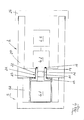
- FIG. 1 shows a printing glass lead-through 1 with a cylindrically shaped metallic frame 11, in which a glass 12 is melted.
- a highly heat-resistant stamp for example, a ceramic stamp having a diameter which corresponds approximately to the inner diameter of the frame 11 is exposed, and about up to a third of the height of the frame eleventh
- liquid glass is filled from above into the interior of the frame. This liquid glass spreads horizontally and eventually touches the inner wall of the frame 11. Once enough glass is filled, it is waited until the glass and the previously heated frame 11 have cooled. Since the metallic frame 11 has a larger temperature coefficient than glass, the metallic frame 11 tries to contract more than the glass. As a result, the pressure tightness is achieved.
- a prefabricated glass rim may be placed in a rotated part and sent through a continuous furnace for melting, so that the glass is also melted into the frame.
- the cylindrically shaped frame 11 has at a first end a circumferentially arranged support collar 13, which widens the frame 11 like a collar. At a second end of the frame 11 a circumferential groove 15 is frontally arranged, in which an O-ring 16 may be arranged.
- the frame 11 is provided over its entire length with an external thread 14. The external thread 14 is used for screwing the pressure glass passage 1 with a housing 2, as will be described later.
- the glass 12 is located halfway up the frame 11 and has a thickness between 0.8 and 1.3 cm. The diameter of the glass is between 2 and 3 cm.
- FIG. 2 shows a plan view from above of the printing glass leadthrough 1 from FIG. 1 , In this illustration, the collar-shaped support collar 13 and a centrally disposed opening with the melted glass 12 can be seen particularly well.
- FIG. 3 shows a plan view from below of the pressure glass duct 1 from the Figures 1 and 2 , In this illustration of the printing glass leadthrough 1, the centrally arranged glass 12 and the circumferential groove 15 arranged at the second end of the frame 11 can be clearly seen.
- the O-ring 16 is in FIG. 3 not shown.
- the support collar 13 can serve both as a mechanical stop when screwing in the pressure glass feedthrough and as a sealing surface, if a further O-ring is arranged on an opposite surface of the housing.
- FIG. 4 shows a radiometric level gauge with an explosion-proof housing 2, in which a pressure glass duct 1, as shown in the FIGS. 1 to 3 has been described, is screwed.
- the housing 2 has a cylindrical body 20, which is closed at the rear by a closure cover 24.
- a passage 21 is arranged with an internal thread 22 into which the pressure glass passage 1 with its external thread 14 can be screwed.
- an O-ring 23 is arranged for further sealing of the housing 2.
- a pot-shaped cover 3 On the front side, a pot-shaped cover 3 is provided in which a hollow-cylindrical lead shield 32 and a cylindrical scintillator 41 seated in the lead shield 32 are arranged.
- the scintillator 41 is seated centrally above the pressure-glass lead-through 1, so that light flashes generated by radioactive radiation in the scintillator the glass 12 can be directed into the interior of the housing 2.
- a photomultiplier 42 which converts the flashes of light from the scintillator 41 into an electrical signal.
- the photomultiplier 42 is followed by a measuring device 43, which calculates a measurement signal from the electrical signals according to a selected measuring arrangement.
- the scintillator may for example also be designed as a tubular. In this case, however, a direction-dependent detection of radioactive radiation is not possible.
- Essential to the invention is the compactly constructed explosion-proof housing 2 with the pressure glass passage 1, which allows a particularly favorable production of such a level gauge.
Landscapes
- Physics & Mathematics (AREA)
- Fluid Mechanics (AREA)
- General Physics & Mathematics (AREA)
- Electromagnetism (AREA)
- Thermal Sciences (AREA)
- Measurement Of Radiation (AREA)
- Measuring Fluid Pressure (AREA)
- Details Of Measuring And Other Instruments (AREA)
Abstract
Description
- Die Erfindung betrifft ein Füllstandmessgerät mit einem explosionssicheren Gehäuse gemäß Oberbegriff des Patentanspruchs 1.
- In der Füllstandmesstechnik ist es oftmals notwendig, Füllstandsensoren bzw. Füllstandmessgeräte in explosionsgefährdeten Umgebungen, beispielsweise in explosionsgefährlichen Dämpfen, anzubringen. Damit von den Füllstandmessgeräten keine Explosionsgefahr ausgeht, werden diese in explosionssicheren (ex-sicheren) Gehäusen untergebracht. Solche explosionssicheren Gehäuse weisen verschiedene Sicherheitsmerkmale auf, die sicherstellen, dass durch die in dem Gehäuse angeordnete Messelektronik kein Zündfunke an die explosionsgefährdete Umgebung abgegeben werden kann. Solche Merkmale sind zum Beispiel die hermetische Verschließung des Gehäuses sowie dessen Erdung.
- Um trotz der hermetischen Kapselung des Gehäuses Messsignale in das Gehäuse sowie Messwerte aus dem Gehäuse zu führen, sind verschiedene Gehäusedurchführungen bekannt. Neben Kabeldurchführungen für Messsignalleitungen gibt es für optisch arbeitende Füllstandmessgeräte sogenannte Druckglasdurchführungen, die mit einem Schauglas ausgestattet sind, durch welches optische Signale in das hermetisch verkapselte Gehäuse geführt werden können. So ist zum Beispiel eine Druckglasdurchführung bekannt, bei der eine dickwandige Glasscheibe in einen Aufnahmering einzementiert und mittels eines weiteren Teiles gegen den Aufnahmering verspannt wird. Diese Verspannung erfolgt über einen zusätzlichen Stempel, der in die Druckglasverschraubung eingeschraubt ist und die Glasplatte gegen den Körper der Druckglasdurchführung presst.
- Die bekannte Ausführungsform hat den Nachteil, dass sie eine extrem große Bauform aufweist und durch die Vielzahl der benötigten Teile aufwändig in ihrer Herstellung ist.
- Aufgabe der Erfindung ist es, ein Füllstandmessgerät mit einem explosionssicherem Gehäuse bereitzustellen, das eine kompakte Bauform aufweist und darüber hinaus einfach und günstig herzustellen ist.
- Diese Aufgabe wird gelöst durch ein Füllstandmessgerät mit den Merkmalen des Patentanspruchs 1.
- Ein solches Füllstandmessgerät mit einem explosionssicheren Gehäuse weist erfindungsgemäß eine Druckglasdurchführung mit einem Glas und einem metallischen Rahmen auf, wobei das Glas in den Rahmen eingeschmolzen ist.
- Da die Druckglasdurchführung zu einem wesentlichen Teil die Größe der Bauform, insbesondere den Durchmesser des Gehäuses eines solchen Füllstandmessgerätes bestimmt, ist es durch eine Druckglasdurchführung mit kleiner Bauform, bei der das Glas direkt in den Rahmen eingeschmolzen ist, möglich, die Größe des Gehäuses wesentlich zu reduzieren. Dadurch, dass die Druckglasdurchführung nur noch aus einem Teil besteht, nämlich dem Rahmen mit dem eingeschmolzenen Glas, sinken auch die Herstellungskosten.
- Idealerweise ist der Rahmen der Druckglasdurchführung zylindrisch ausgeformt und weist ein Außengewinde auf. Durch eine derartige Ausgestaltung ist die Druckglasdurchführung in das Gehäuse des Füllstandmessgerätes einschraubbar und bei einer ausreichend langen Ausbildung des Gewindes wird somit auch den Ex-Vorschriften Genüge getan. Das Gewinde weist dazu beispielsweise eine Länge von mindestens einem Zentimeter auf. Diese Länge hängt u.a. von der Steigung und vom Volumen des Gehäuses ab und muss gegebenenfalls nach den geltenden Vorschriften für explosionssichere Gehäuse bestimmt werden.
- In einer Weiterbildung der Erfindung weist der metallische Rahmen an einem ersten Ende einen umlaufend angeordneten Auflagebund auf, während an einem zweiten Ende stirnseitig vorzugsweise eine umlaufende Nut angeordnet ist. Der Auflagebund kann dabei als zusätzliche Dichtfläche, beispielsweise mit einem entsprechend angeordneten O-Ring verwendet werden. In der Nut am zweiten Ende des Rahmens kann ebenfalls ein O-Ring angebracht werden, der einerseits eine dichtende Wirkung gewährleistet, andererseits aber auch zur lichtdichten Ankopplung, an beispielsweise einen Photomultiplier, dienen kann.
- Das Füllstandmessgerät kann zum Beispiel einen Szintillationszähler zur Detektion radioaktiver Strahlung aufweisen. In diesem Fall ist die Druckglasdurchführung zwischen einem Szintillator und den Photomultiplier angeordnet und ist vorteilhafterweise Bestandteil einer Wandung des Gehäuses. Insbesondere bei radiometrischen Füllstandmessgeräten, zum Beispiel einem Szintillationszähler, ist es notwendig, die Elektronik explosionssicher zu verkapseln und dabei aber Lichtimpulse vom Szintillator einkoppeln zu können. Die explosionssichere Verkapselung der Elektronik ist insbesondere notwendig, da der Photomultiplier mit sehr hohen Spannungen arbeitet und so ein erhöhtes Explosionsrisiko durch Funkenbildung besteht. Bei einem zylindrisch ausgeformten Gehäuse des Füllstandmessgerätes ist es zum Beispiel möglich, die Druckglasdurchführung in einer der Deckelflächen des Gehäuses einzuschrauben. Die Druckglasdurchführung kann hierfür beispielsweise als separat handhabbare Einheit ausgebildet sein, sodass eine getrennte Herstellung des Gehäuses und der Druckglasdurchführung möglich ist.
- Zur Gewährleistung einer möglichst verlustfreien Einkopplung von optischen Signalen ist das Glas poliert und geläppt. Durch das Polieren und Läppen wird eine große Glattheit der Oberfläche des Glases erreicht, sodass keine Verluste durch Reflexion oder Streuung der optischen Signale erfolgen.
- In einer Weiterbildung der Erfindung kann um den vorderseitig angeordneten Szintillator eine hohlzylinderförmige Bleiabschirmung angeordnet sein, die bewirkt, dass auf den Szintillator nur radioaktive Strahlung aus axialer Richtung wirkt. Auf diese Weise kann besonders einfach eine Richtungsabhängigkeit der Detektion erreicht werden.
- Die Erfindung wird nachfolgend anhand eines Ausführungsbeispiels unter Bezugnahme auf die beigefügten Figuren ausführlich beschrieben. Es zeigen:
- Figur 1
- eine Schnittdarstellung der erfindungsgemäßen Druckglasdurchführung,
- Figur 2
- die Druckglasdurchführung aus
Figur 1 in Draufsicht von oben, - Figur 3
- die Druckglasdurchführung aus den
Figuren 1 und 2 in einer Draufsicht von unten und - Figur 4
- eine Schnittdarstellung eines Füllstandmessgerätes mit einem explosionssicheren Gehäuse und einer Druckglasdurchführung wie sie in den
Figuren 1 bis 3 dargestellt ist. -
Figur 1 zeigt eine Druckglasdurchführung 1 mit einem zylinderförmig ausgeführten metallischen Rahmen 11, in den ein Glas 12 eingeschmolzen ist. Das Einschmelzen des Glases erfolgt dadurch, dass in den metallischen Rahmen ein hochhitzebeständiger Stempel, zum Beispiel ein Keramikstempel, der einen Durchmesser aufweist, welcher etwa dem Innendurchmesser des Rahmens 11 entspricht, ausgesetzt wird und zwar etwa bis zu einem Drittel der Höhe des Rahmens 11. Anschließend wird flüssiges Glas von oben her in das Innere des Rahmens gefüllt. Dieses flüssige Glas breitet sich horizontal aus und berührt schließlich die Innenwandung des Rahmens 11. Sobald genügend Glas eingefüllt ist, wird gewartet, bis sich das Glas und der zuvor erhitzte Rahmen 11 abgekühlt haben. Da der metallische Rahmen 11 einen größeren Temperaturkoeffizienten als Glas hat, versucht sich der metallische Rahmen 11 mehr zusammenzuziehen als das Glas. Hierdurch wird die Druckdichtigkeit erreicht. Alternativ kann eine vorgefertigte Glasronde in ein gedrehtes Teil eingelegt und zum Schmelzen durch einen Durchlaufofen geschickt werden, so dass das Glas ebenfalls in den Rahmen eingeschmolzen wird. - Der zylinderförmig ausgeführte Rahmen 11 weist an einem ersten Ende einen umfänglich angeordneten Auflagebund 13 auf, der den Rahmen 11 kragenförmig verbreitert. An einem zweiten Ende des Rahmens 11 ist stirnseitig eine umlaufende Nut 15 angeordnet, in der ein O-Ring 16 angeordnet sein kann. Der Rahmen 11 ist über seine gesamte Länge mit einem Außengewinde 14 versehen. Das Außengewinde 14 dient zur Verschraubung der Druckglasdurchführung 1 mit einem Gehäuse 2, wie es später beschrieben wird. Das Glas 12 ist auf halber Höhe des Rahmens 11 angeordnet und weist eine Dicke zwischen 0,8 und 1,3 cm auf. Der Durchmesser des Glases beträgt zwischen 2 und 3 cm.
-
Figur 2 zeigt eine Draufsicht von oben auf die Druckglasdurchführung 1 ausFigur 1 . In dieser Darstellung ist besonders gut der kragenförmige Auflagebund 13 sowie eine mittig angeordnete Öffnung mit dem eingeschmolzenen Glas 12 zu erkennen. -
Figur 3 zeigt eine Draufsicht von unten auf die Druckglasdurchführung 1 aus denFiguren 1 und 2 . In dieser Darstellung der Druckglasdurchführung 1 ist das mittig angeordnete Glas 12 sowie die am zweiten Ende des Rahmens 11 angeordnete umlaufende Nut 15 deutlich zu erkennen. Der O-Ring 16 ist inFigur 3 nicht dargestellt. Der Auflagebund 13 kann sowohl als mechanischer Anschlag beim Einschrauben der Druckglasdurchführung als auch als Dichtfläche dienen, wenn an einer gegenüberliegenden Fläche des Gehäuses ein weiterer O-Ring angeordnet ist. -
Figur 4 zeigt ein radiometrisches Füllstandmessgerät mit einem explosionssicheren Gehäuse 2, in das eine Druckglasdurchführung 1, wie sie in denFiguren 1 bis 3 beschrieben wurde, eingeschraubt ist. Das Gehäuse 2 weist einen zylindrischen Körper 20 auf, der rückseitig durch einen Verschlussdeckel 24 verschließbar ist. In einer vorderseitigen Deckfläche des Körpers 20 ist eine Durchführung 21 mit einem Innengewinde 22 angeordnet, in das die Druckglasdurchführung 1 mit ihrem Außengewinde 14 einschraubbar ist. Zwischen dem Auflagebund 13 der Druckglasdurchführung 1 und der vorderseitigen Deckfläche des Körpers 20 ist ein O-Ring 23 zur weiteren Abdichtung des Gehäuses 2 angeordnet. Vorderseitig ist ein topfförmiger Deckel 3 vorgesehen, in dem eine hohlzylinderförmige Bleiabschirmung 32 sowie ein, in der Bleiabschirmung 32 sitzender zylinderförmiger Szintillator 41 angeordnet sind. Der Szintillator 41 sitzt zentral über der Druckglasdurchführung 1, sodass durch radioaktive Strahlung im Szintillator erzeugte Lichtblitze durch das Glas 12 ins Innere des Gehäuses 2 geleitet werden können. Im Inneren des Gehäuses 2 sitzt ein Photomultiplier 42, der die Lichtblitze aus dem Szintillator 41 in ein elektrisches Signal umwandelt. Dem Photomultiplier 42 ist ein Messgerät 43 nachgeschaltet, das aus den elektrischen Signalen gemäß einer gewählten Messanordnung ein Messsignal errechnet. - Es ist anzumerken, dass der Szintillator beispielsweise auch als schlauchförmig ausgebildet sein kann. In diesem Fall ist jedoch ein richtungsabhängiges Detektieren von radioaktiver Strahlung nicht möglich.
- Erfindungswesentlich ist das kompakt gebaute explosionssichere Gehäuse 2 mit der Druckglasdurchführung 1, das eine besonders günstige Herstellung eines solchen Füllstandmessgerätes ermöglicht.
- Bezugszeichenliste
- 1
- Druckglasdurchführung
- 2
- Gehäuse
- 3
- Deckel
- 4
- Szintillationszähler
- 11
- Rahmen
- 12
- Glas
- 13
- Auflagebund
- 14
- Außengewinde
- 15
- Nut
- 16
- O-Ring
- 20
- Körper
- 21
- Durchführung
- 22
- Innengewinde
- 23
- O-Ring
- 24
- Verschlussdeckel
- 32
- Bleiabschirmung
- 41
- Szintillator
- 42
- Photomultiplier
- 43
- Messgerät
Claims (16)
- Füllstandmessgerät mit einem explosionssicheren Gehäuse (2), das eine Druckglasdurchführung (1) mit einem Glas (12) und einem metallischen Rahmen (11) aufweist,
dadurch gekennzeichnet, dass das Glas (12) in den Rahmen (11) eingeschmolzen ist. - Füllstandmessgerät nach Anspruch 1,
dadurch gekennzeichnet, dass der Rahmen (11) zylindrisch ausgeformt ist. - Füllstandmessgerät nach einem der Anspruch 2,
dadurch gekennzeichnet, dass der Rahmen (11) ein Außengewinde (14) aufweist. - Füllstandmessgerät nach Anspruch 3,
dadurch gekennzeichnet, dass das Außengewinde (14) eine Länge von mindestens 1 cm aufweist. - Füllstandmessgerät nach einem der vorhergehenden Ansprüche,
dadurch gekennzeichnet, dass der Rahmen (11) an einem ersten Ende einen umlaufend angeordneten Auflagebund (13) aufweist. - Füllstandmessgerät nach einem der vorhergehenden Ansprüche,
dadurch gekennzeichnet, dass der Rahmen (11) an einem zweiten Ende eine stirnseitig angeordnete umlaufende Nut (15) aufweist. - Füllstandmessgerät nach einem der vorhergehenden Ansprüche,
dadurch gekennzeichnet, dass das Füllstandmessgerät einen Szintillationszähler (4) aufweist. - Füllstandmessgerät nach Anspruch 7,
dadurch gekennzeichnet, dass die Druckglasdurchführung (1) zwischen einem Szintillator (4, 1) und einem Photomultiplier (42) angeordnet ist. - Füllstandmessgerät nach einem der vorhergehenden Ansprüche,
dadurch gekennzeichnet, dass die Druckglasdurchführung (1) Bestandteil einer Wandung des Gehäuses (2) ist. - Füllstandmessgerät nach einem der vorhergehenden Ansprüche,
dadurch gekennzeichnet, dass die Druckglasdurchführung (1) eine separat handhabbare Einheit ist. - Füllstandmessgerät nach einem der vorhergehenden Ansprüche,
dadurch gekennzeichnet, dass das Glas (12) poliert und geläppt ist. - Füllstandmessgerät nach einem der vorhergehenden Ansprüche,
dadurch gekennzeichnet, dass das Glas (12) einen Durchmesser zwischen 2 und 3 cm aufweist. - Füllstandmessgerät nach einem der vorhergehenden Ansprüche,
dadurch gekennzeichnet, dass das Glas (12) eine Dicke zwischen 0,8 und 1,3 cm aufweist. - Füllstandmessgerät nach einem der vorhergehenden Ansprüche,
dadurch gekennzeichnet, dass das Glas (12) auf halber Höhe des Rahmens (11) sitzt. - Füllstandmessgerät nach einem der vorhergehenden Ansprüche,
dadurch gekennzeichnet, dass das Gehäuse (2) aus Metall gefertigt ist. - Füllstandmessgerät nach einem der vorhergehenden Ansprüche,
dadurch gekennzeichnet, dass dass um den Szintillator (41) eine hohlzylinderförmige Bleiabschirmung (32) angeordnet ist.
Applications Claiming Priority (1)
| Application Number | Priority Date | Filing Date | Title |
|---|---|---|---|
| DE102007048203A DE102007048203A1 (de) | 2007-10-08 | 2007-10-08 | Füllstandmessgerät mit explosionssicherem Gehäuse |
Publications (3)
| Publication Number | Publication Date |
|---|---|
| EP2048483A2 true EP2048483A2 (de) | 2009-04-15 |
| EP2048483A3 EP2048483A3 (de) | 2010-07-28 |
| EP2048483B1 EP2048483B1 (de) | 2019-04-03 |
Family
ID=39952169
Family Applications (1)
| Application Number | Title | Priority Date | Filing Date |
|---|---|---|---|
| EP08012551.1A Not-in-force EP2048483B1 (de) | 2007-10-08 | 2008-07-11 | Füllstandmessgerät mit explosionssicherem Gehäuse |
Country Status (4)
| Country | Link |
|---|---|
| US (1) | US8069724B2 (de) |
| EP (1) | EP2048483B1 (de) |
| CN (1) | CN101408447B (de) |
| DE (1) | DE102007048203A1 (de) |
Cited By (3)
| Publication number | Priority date | Publication date | Assignee | Title |
|---|---|---|---|---|
| WO2012107208A3 (de) * | 2011-02-09 | 2012-11-22 | Krohne Messtechnik Gmbh | Explosionsgeschütztes gerät |
| WO2016124459A1 (de) * | 2015-02-06 | 2016-08-11 | Endress+Hauser Gmbh+Co. Kg | Messanordnung zur radiometrischen dichte- oder füllstandsmessung eines mediums in einem explosionsgefärdeten bereich |
| EP3196607A1 (de) * | 2016-01-25 | 2017-07-26 | Berthold Technologies GmbH & Co. KG | Radiometrisches prozessmesssystem |
Families Citing this family (13)
| Publication number | Priority date | Publication date | Assignee | Title |
|---|---|---|---|---|
| GB0914583D0 (en) * | 2009-08-20 | 2009-09-30 | Johnson Matthey Plc | Level measurement apparatus |
| GB0917216D0 (en) | 2009-10-01 | 2009-11-18 | Johnson Matthey Plc | Method and apparatus for determining a fluid density |
| DE102012001911A1 (de) * | 2012-02-02 | 2013-08-08 | Krohne Messtechnik Gmbh | Nach dem Radar-Prinzip arbeitendes Füllstandsmesssystem |
| US9316522B2 (en) * | 2012-08-08 | 2016-04-19 | Eaton Corporation | Visual indicator with sensor |
| US9316524B2 (en) | 2012-08-08 | 2016-04-19 | Eaton Corporation | Visual indicator with sensor |
| JP2015106592A (ja) * | 2013-11-28 | 2015-06-08 | アズビル株式会社 | 透光部材の取付構造および防爆機器 |
| EP3176547B1 (de) | 2015-12-02 | 2018-09-19 | Siemens Aktiengesellschaft | Gehäuseteil für eine messvorrichtung mit einem mikrowellendurchlässigen glas oder keramikfenster |
| DE102016105385A1 (de) * | 2016-03-22 | 2017-09-28 | Vega Grieshaber Kg | Sensorgehäuse und Sensor mit Sensorgehäuse |
| DE102016122049A1 (de) | 2016-11-16 | 2018-05-17 | Endress+Hauser SE+Co. KG | Detektor-Einheit für ein radiometrisches Dichte- oder Füllstandsmessgerät |
| DE102022103694B3 (de) | 2022-02-16 | 2023-05-04 | Vega Grieshaber Kg | Radiometrische Messanordnung mit verschiebbar gelagerter Druckglasdurchführung |
| DE102022130563B4 (de) | 2022-11-18 | 2024-09-26 | Vega Grieshaber Kg | Elektronikeinheit für ein Messgerät |
| JP2025050542A (ja) * | 2023-09-25 | 2025-04-04 | 株式会社キーエンス | 本質安全防爆のレベル計 |
| DE102024123254A1 (de) * | 2024-08-14 | 2026-02-19 | Auma Riester Gmbh & Co. Kg | Fenster für einen Stellantrieb und ein Stellantrieb mit Fenster |
Family Cites Families (19)
| Publication number | Priority date | Publication date | Assignee | Title |
|---|---|---|---|---|
| US3032659A (en) * | 1958-09-04 | 1962-05-01 | Corning Glass Works | Scintillator |
| US3930160A (en) * | 1974-02-11 | 1975-12-30 | Kewanee Oil Co | Grooved windows for scintillation crystals and light pipes of high refractive index |
| DE2734897A1 (de) * | 1977-08-03 | 1979-02-15 | Sundstrand Deutschland Gmbh | Einrichtung zur fluessigkeitsstandanzeige |
| US4162826A (en) * | 1978-03-20 | 1979-07-31 | Sybron Corporation | Sight glass assembly and method for its production |
| US4224047A (en) * | 1979-01-25 | 1980-09-23 | The Singer Company | Method of fusing a sight glass to a metal part |
| DE3129386A1 (de) * | 1981-07-25 | 1983-02-10 | Basf Ag, 6700 Ludwigshafen | Fluessigkeitsstandanzeiger fuer hohe druecke |
| US4809862A (en) * | 1987-03-13 | 1989-03-07 | Canty Thomas M | Fuseview laminate safety sight glass |
| US4788929A (en) * | 1988-06-14 | 1988-12-06 | Parker-Hannifin Corporation | Fluid indicator for refrigeration system |
| CN2035872U (zh) * | 1988-10-18 | 1989-04-12 | 何冠勇 | 光电液位监测装置 |
| US4977418A (en) * | 1989-10-03 | 1990-12-11 | Canty Thomas M | Camera viewing unit |
| JPH0464021A (ja) | 1990-07-03 | 1992-02-28 | Nkk Corp | タールデカンターの界面監視方法 |
| CN2101853U (zh) * | 1991-05-17 | 1992-04-15 | 江苏常州潞城鹤翔五金机械厂 | 金属玻璃观察镜 |
| US5763776A (en) * | 1996-02-20 | 1998-06-09 | Vickers, Inc. | Self-sealing sight glass for a fluid vessel |
| DE19850509A1 (de) * | 1998-11-03 | 2000-05-04 | Ksr Kuebler Niveau Messtechnik | Bypass-Niveaustandanzeigevorrichtung |
| KR100336524B1 (ko) * | 2000-08-07 | 2002-05-11 | 윤종용 | 반도체 제조용 화학기상증착 장치의 뷰우포트 |
| US6359742B1 (en) * | 2001-04-27 | 2002-03-19 | J. M. Canty, Inc. | Weldable sightglass assembly |
| US6639745B1 (en) * | 2002-06-25 | 2003-10-28 | Kuo-Chung Cheng | Observation window of a hyperbaric chamber |
| US7132662B2 (en) * | 2003-03-28 | 2006-11-07 | Ronan Engineering Company | Flexible liquid-filled radiation detector scintillator |
| DE102006019688B4 (de) * | 2006-04-27 | 2014-10-23 | Vega Grieshaber Kg | Patchantenne mit Keramikscheibe als Abdeckung |
-
2007
- 2007-10-08 DE DE102007048203A patent/DE102007048203A1/de not_active Ceased
-
2008
- 2008-07-11 EP EP08012551.1A patent/EP2048483B1/de not_active Not-in-force
- 2008-08-28 CN CN2008102130930A patent/CN101408447B/zh not_active Expired - Fee Related
- 2008-10-01 US US12/285,276 patent/US8069724B2/en active Active
Cited By (4)
| Publication number | Priority date | Publication date | Assignee | Title |
|---|---|---|---|---|
| WO2012107208A3 (de) * | 2011-02-09 | 2012-11-22 | Krohne Messtechnik Gmbh | Explosionsgeschütztes gerät |
| WO2016124459A1 (de) * | 2015-02-06 | 2016-08-11 | Endress+Hauser Gmbh+Co. Kg | Messanordnung zur radiometrischen dichte- oder füllstandsmessung eines mediums in einem explosionsgefärdeten bereich |
| DE102015101705B4 (de) | 2015-02-06 | 2023-04-27 | Endress+Hauser SE+Co. KG | Messanordnung zur radiometrischen Dichte- oder Füllstandsmessung eines Mediums in einem explosionsgefährdeten Bereich |
| EP3196607A1 (de) * | 2016-01-25 | 2017-07-26 | Berthold Technologies GmbH & Co. KG | Radiometrisches prozessmesssystem |
Also Published As
| Publication number | Publication date |
|---|---|
| US8069724B2 (en) | 2011-12-06 |
| EP2048483A3 (de) | 2010-07-28 |
| CN101408447B (zh) | 2012-06-27 |
| CN101408447A (zh) | 2009-04-15 |
| EP2048483B1 (de) | 2019-04-03 |
| US20090114012A1 (en) | 2009-05-07 |
| DE102007048203A1 (de) | 2009-04-09 |
Similar Documents
| Publication | Publication Date | Title |
|---|---|---|
| EP2048483B1 (de) | Füllstandmessgerät mit explosionssicherem Gehäuse | |
| EP2673595B1 (de) | Explosionsgeschütztes gerät | |
| DE102008010207B4 (de) | Optische Baugruppe zum Ein- und/oder Auskoppeln von elektromagnetischer Strahlung in ein druckfestes Gehäuse und/oder aus einem druckfesten Gehäuse | |
| EP3380814A1 (de) | Explosionsgeschütztes gehäuse für mittel zum senden und empfangen elektromagnetischer strahlung | |
| EP1128172A1 (de) | Drucksensor | |
| EP2359098B1 (de) | Differenzdruckmessumformer | |
| DE102005021176A1 (de) | Elektrisches mikrooptisches Modul mit verbesserten Verbindungsstrukturen | |
| EP3546895A1 (de) | Vorrichtung und verfahren zum betreiben eines beheizbaren sensors, insbesondere in einer explosionsfähigen atmosphäre | |
| EP3876372B1 (de) | Explosionsgeschützte vorrichtung | |
| EP3701230B1 (de) | Zählereinrichtung | |
| EP0527368A1 (de) | Kabeldurchführungsvorrichtung | |
| EP2414791B1 (de) | Abdichtvorrichtung für eine vorrichtung zur füllstandsmessung in einem druckbehälter einer kerntechnischen anlage | |
| DE102016122049A1 (de) | Detektor-Einheit für ein radiometrisches Dichte- oder Füllstandsmessgerät | |
| EP0813076B1 (de) | Berührungslos wirkende Schutzeinrichtung, insbesondere Lichtschrankengitter | |
| DE102022103694B3 (de) | Radiometrische Messanordnung mit verschiebbar gelagerter Druckglasdurchführung | |
| WO2013143693A2 (de) | Messgerätgehäuse mit sichtscheibe | |
| DE102010034888B4 (de) | Druckfest gekapseltes Gehäuse und Anordnung mit einem Verteilerblock undeinem solchen Gehäuse | |
| EP0752575B1 (de) | Wägezelle | |
| DE4410821A1 (de) | Vorrichtung zur Beobachtung einer Körperhöhle | |
| DE2114449C3 (de) | Lasergerät für den Einsatz in Schlagwetter- oder explosionsgefährdeten Betrieben | |
| EP2381228B1 (de) | Messsonde mit Schutzeinrichtung gegen ein Messmedium und Verfahren zum Herstellen einer solchen Messsonde | |
| DE3729411A1 (de) | Optik fuer strahlungssensor | |
| DE9315086U1 (de) | Druckaufnehmer | |
| EP0997687A1 (de) | Rohrförmige Heiz- oder Messvorrichtung | |
| EP3065228A1 (de) | Explosionsgeschützte kabelverschraubung |
Legal Events
| Date | Code | Title | Description |
|---|---|---|---|
| PUAI | Public reference made under article 153(3) epc to a published international application that has entered the european phase |
Free format text: ORIGINAL CODE: 0009012 |
|
| AK | Designated contracting states |
Kind code of ref document: A2 Designated state(s): AT BE BG CH CY CZ DE DK EE ES FI FR GB GR HR HU IE IS IT LI LT LU LV MC MT NL NO PL PT RO SE SI SK TR |
|
| AX | Request for extension of the european patent |
Extension state: AL BA MK RS |
|
| PUAL | Search report despatched |
Free format text: ORIGINAL CODE: 0009013 |
|
| AK | Designated contracting states |
Kind code of ref document: A3 Designated state(s): AT BE BG CH CY CZ DE DK EE ES FI FR GB GR HR HU IE IS IT LI LT LU LV MC MT NL NO PL PT RO SE SI SK TR |
|
| AX | Request for extension of the european patent |
Extension state: AL BA MK RS |
|
| RIC1 | Information provided on ipc code assigned before grant |
Ipc: G01F 23/02 20060101ALI20100624BHEP Ipc: G01F 23/288 20060101AFI20081120BHEP |
|
| 17P | Request for examination filed |
Effective date: 20101012 |
|
| AKX | Designation fees paid |
Designated state(s): AT BE BG CH CY CZ DE DK EE ES FI FR GB GR HR HU IE IS IT LI LT LU LV MC MT NL NO PL PT RO SE SI SK TR |
|
| 17Q | First examination report despatched |
Effective date: 20140528 |
|
| STAA | Information on the status of an ep patent application or granted ep patent |
Free format text: STATUS: EXAMINATION IS IN PROGRESS |
|
| GRAP | Despatch of communication of intention to grant a patent |
Free format text: ORIGINAL CODE: EPIDOSNIGR1 |
|
| STAA | Information on the status of an ep patent application or granted ep patent |
Free format text: STATUS: GRANT OF PATENT IS INTENDED |
|
| INTG | Intention to grant announced |
Effective date: 20181025 |
|
| GRAS | Grant fee paid |
Free format text: ORIGINAL CODE: EPIDOSNIGR3 |
|
| GRAA | (expected) grant |
Free format text: ORIGINAL CODE: 0009210 |
|
| STAA | Information on the status of an ep patent application or granted ep patent |
Free format text: STATUS: THE PATENT HAS BEEN GRANTED |
|
| AK | Designated contracting states |
Kind code of ref document: B1 Designated state(s): AT BE BG CH CY CZ DE DK EE ES FI FR GB GR HR HU IE IS IT LI LT LU LV MC MT NL NO PL PT RO SE SI SK TR |
|
| REG | Reference to a national code |
Ref country code: GB Ref legal event code: FG4D Free format text: NOT ENGLISH |
|
| REG | Reference to a national code |
Ref country code: CH Ref legal event code: EP Ref country code: AT Ref legal event code: REF Ref document number: 1116311 Country of ref document: AT Kind code of ref document: T Effective date: 20190415 |
|
| REG | Reference to a national code |
Ref country code: DE Ref legal event code: R096 Ref document number: 502008016679 Country of ref document: DE |
|
| REG | Reference to a national code |
Ref country code: IE Ref legal event code: FG4D Free format text: LANGUAGE OF EP DOCUMENT: GERMAN |
|
| REG | Reference to a national code |
Ref country code: NL Ref legal event code: MP Effective date: 20190403 |
|
| REG | Reference to a national code |
Ref country code: LT Ref legal event code: MG4D |
|
| PG25 | Lapsed in a contracting state [announced via postgrant information from national office to epo] |
Ref country code: NL Free format text: LAPSE BECAUSE OF FAILURE TO SUBMIT A TRANSLATION OF THE DESCRIPTION OR TO PAY THE FEE WITHIN THE PRESCRIBED TIME-LIMIT Effective date: 20190403 |
|
| PG25 | Lapsed in a contracting state [announced via postgrant information from national office to epo] |
Ref country code: SE Free format text: LAPSE BECAUSE OF FAILURE TO SUBMIT A TRANSLATION OF THE DESCRIPTION OR TO PAY THE FEE WITHIN THE PRESCRIBED TIME-LIMIT Effective date: 20190403 Ref country code: ES Free format text: LAPSE BECAUSE OF FAILURE TO SUBMIT A TRANSLATION OF THE DESCRIPTION OR TO PAY THE FEE WITHIN THE PRESCRIBED TIME-LIMIT Effective date: 20190403 Ref country code: HR Free format text: LAPSE BECAUSE OF FAILURE TO SUBMIT A TRANSLATION OF THE DESCRIPTION OR TO PAY THE FEE WITHIN THE PRESCRIBED TIME-LIMIT Effective date: 20190403 Ref country code: NO Free format text: LAPSE BECAUSE OF FAILURE TO SUBMIT A TRANSLATION OF THE DESCRIPTION OR TO PAY THE FEE WITHIN THE PRESCRIBED TIME-LIMIT Effective date: 20190703 Ref country code: PT Free format text: LAPSE BECAUSE OF FAILURE TO SUBMIT A TRANSLATION OF THE DESCRIPTION OR TO PAY THE FEE WITHIN THE PRESCRIBED TIME-LIMIT Effective date: 20190803 Ref country code: CZ Free format text: LAPSE BECAUSE OF FAILURE TO SUBMIT A TRANSLATION OF THE DESCRIPTION OR TO PAY THE FEE WITHIN THE PRESCRIBED TIME-LIMIT Effective date: 20190403 Ref country code: FI Free format text: LAPSE BECAUSE OF FAILURE TO SUBMIT A TRANSLATION OF THE DESCRIPTION OR TO PAY THE FEE WITHIN THE PRESCRIBED TIME-LIMIT Effective date: 20190403 Ref country code: LT Free format text: LAPSE BECAUSE OF FAILURE TO SUBMIT A TRANSLATION OF THE DESCRIPTION OR TO PAY THE FEE WITHIN THE PRESCRIBED TIME-LIMIT Effective date: 20190403 |
|
| PG25 | Lapsed in a contracting state [announced via postgrant information from national office to epo] |
Ref country code: PL Free format text: LAPSE BECAUSE OF FAILURE TO SUBMIT A TRANSLATION OF THE DESCRIPTION OR TO PAY THE FEE WITHIN THE PRESCRIBED TIME-LIMIT Effective date: 20190403 Ref country code: GR Free format text: LAPSE BECAUSE OF FAILURE TO SUBMIT A TRANSLATION OF THE DESCRIPTION OR TO PAY THE FEE WITHIN THE PRESCRIBED TIME-LIMIT Effective date: 20190704 Ref country code: LV Free format text: LAPSE BECAUSE OF FAILURE TO SUBMIT A TRANSLATION OF THE DESCRIPTION OR TO PAY THE FEE WITHIN THE PRESCRIBED TIME-LIMIT Effective date: 20190403 Ref country code: BG Free format text: LAPSE BECAUSE OF FAILURE TO SUBMIT A TRANSLATION OF THE DESCRIPTION OR TO PAY THE FEE WITHIN THE PRESCRIBED TIME-LIMIT Effective date: 20190703 |
|
| PG25 | Lapsed in a contracting state [announced via postgrant information from national office to epo] |
Ref country code: IS Free format text: LAPSE BECAUSE OF FAILURE TO SUBMIT A TRANSLATION OF THE DESCRIPTION OR TO PAY THE FEE WITHIN THE PRESCRIBED TIME-LIMIT Effective date: 20190803 |
|
| REG | Reference to a national code |
Ref country code: DE Ref legal event code: R097 Ref document number: 502008016679 Country of ref document: DE |
|
| PG25 | Lapsed in a contracting state [announced via postgrant information from national office to epo] |
Ref country code: DK Free format text: LAPSE BECAUSE OF FAILURE TO SUBMIT A TRANSLATION OF THE DESCRIPTION OR TO PAY THE FEE WITHIN THE PRESCRIBED TIME-LIMIT Effective date: 20190403 Ref country code: EE Free format text: LAPSE BECAUSE OF FAILURE TO SUBMIT A TRANSLATION OF THE DESCRIPTION OR TO PAY THE FEE WITHIN THE PRESCRIBED TIME-LIMIT Effective date: 20190403 Ref country code: RO Free format text: LAPSE BECAUSE OF FAILURE TO SUBMIT A TRANSLATION OF THE DESCRIPTION OR TO PAY THE FEE WITHIN THE PRESCRIBED TIME-LIMIT Effective date: 20190403 Ref country code: SK Free format text: LAPSE BECAUSE OF FAILURE TO SUBMIT A TRANSLATION OF THE DESCRIPTION OR TO PAY THE FEE WITHIN THE PRESCRIBED TIME-LIMIT Effective date: 20190403 |
|
| PLBE | No opposition filed within time limit |
Free format text: ORIGINAL CODE: 0009261 |
|
| STAA | Information on the status of an ep patent application or granted ep patent |
Free format text: STATUS: NO OPPOSITION FILED WITHIN TIME LIMIT |
|
| PG25 | Lapsed in a contracting state [announced via postgrant information from national office to epo] |
Ref country code: MC Free format text: LAPSE BECAUSE OF FAILURE TO SUBMIT A TRANSLATION OF THE DESCRIPTION OR TO PAY THE FEE WITHIN THE PRESCRIBED TIME-LIMIT Effective date: 20190403 Ref country code: IT Free format text: LAPSE BECAUSE OF FAILURE TO SUBMIT A TRANSLATION OF THE DESCRIPTION OR TO PAY THE FEE WITHIN THE PRESCRIBED TIME-LIMIT Effective date: 20190403 |
|
| REG | Reference to a national code |
Ref country code: CH Ref legal event code: PL |
|
| 26N | No opposition filed |
Effective date: 20200106 |
|
| PG25 | Lapsed in a contracting state [announced via postgrant information from national office to epo] |
Ref country code: TR Free format text: LAPSE BECAUSE OF FAILURE TO SUBMIT A TRANSLATION OF THE DESCRIPTION OR TO PAY THE FEE WITHIN THE PRESCRIBED TIME-LIMIT Effective date: 20190403 |
|
| REG | Reference to a national code |
Ref country code: BE Ref legal event code: MM Effective date: 20190731 |
|
| PG25 | Lapsed in a contracting state [announced via postgrant information from national office to epo] |
Ref country code: CH Free format text: LAPSE BECAUSE OF NON-PAYMENT OF DUE FEES Effective date: 20190731 Ref country code: SI Free format text: LAPSE BECAUSE OF FAILURE TO SUBMIT A TRANSLATION OF THE DESCRIPTION OR TO PAY THE FEE WITHIN THE PRESCRIBED TIME-LIMIT Effective date: 20190403 Ref country code: BE Free format text: LAPSE BECAUSE OF NON-PAYMENT OF DUE FEES Effective date: 20190731 Ref country code: LU Free format text: LAPSE BECAUSE OF NON-PAYMENT OF DUE FEES Effective date: 20190711 Ref country code: LI Free format text: LAPSE BECAUSE OF NON-PAYMENT OF DUE FEES Effective date: 20190731 |
|
| PG25 | Lapsed in a contracting state [announced via postgrant information from national office to epo] |
Ref country code: FR Free format text: LAPSE BECAUSE OF NON-PAYMENT OF DUE FEES Effective date: 20190731 |
|
| PG25 | Lapsed in a contracting state [announced via postgrant information from national office to epo] |
Ref country code: IE Free format text: LAPSE BECAUSE OF NON-PAYMENT OF DUE FEES Effective date: 20190711 |
|
| REG | Reference to a national code |
Ref country code: AT Ref legal event code: MM01 Ref document number: 1116311 Country of ref document: AT Kind code of ref document: T Effective date: 20190711 |
|
| PG25 | Lapsed in a contracting state [announced via postgrant information from national office to epo] |
Ref country code: AT Free format text: LAPSE BECAUSE OF NON-PAYMENT OF DUE FEES Effective date: 20190711 |
|
| PG25 | Lapsed in a contracting state [announced via postgrant information from national office to epo] |
Ref country code: CY Free format text: LAPSE BECAUSE OF FAILURE TO SUBMIT A TRANSLATION OF THE DESCRIPTION OR TO PAY THE FEE WITHIN THE PRESCRIBED TIME-LIMIT Effective date: 20190403 |
|
| PG25 | Lapsed in a contracting state [announced via postgrant information from national office to epo] |
Ref country code: HU Free format text: LAPSE BECAUSE OF FAILURE TO SUBMIT A TRANSLATION OF THE DESCRIPTION OR TO PAY THE FEE WITHIN THE PRESCRIBED TIME-LIMIT; INVALID AB INITIO Effective date: 20080711 Ref country code: MT Free format text: LAPSE BECAUSE OF FAILURE TO SUBMIT A TRANSLATION OF THE DESCRIPTION OR TO PAY THE FEE WITHIN THE PRESCRIBED TIME-LIMIT Effective date: 20190403 |
|
| P01 | Opt-out of the competence of the unified patent court (upc) registered |
Effective date: 20230626 |
|
| PGFP | Annual fee paid to national office [announced via postgrant information from national office to epo] |
Ref country code: DE Payment date: 20240719 Year of fee payment: 17 |
|
| PGFP | Annual fee paid to national office [announced via postgrant information from national office to epo] |
Ref country code: GB Payment date: 20240723 Year of fee payment: 17 |
|
| REG | Reference to a national code |
Ref country code: DE Ref legal event code: R119 Ref document number: 502008016679 Country of ref document: DE |
|
| GBPC | Gb: european patent ceased through non-payment of renewal fee |
Effective date: 20250711 |
|
| PG25 | Lapsed in a contracting state [announced via postgrant information from national office to epo] |
Ref country code: GB Free format text: LAPSE BECAUSE OF NON-PAYMENT OF DUE FEES Effective date: 20250711 |
|
| PG25 | Lapsed in a contracting state [announced via postgrant information from national office to epo] |
Ref country code: DE Free format text: LAPSE BECAUSE OF NON-PAYMENT OF DUE FEES Effective date: 20260203 |