EP2048457A1 - Refrigeration device - Google Patents
Refrigeration device Download PDFInfo
- Publication number
- EP2048457A1 EP2048457A1 EP07791431A EP07791431A EP2048457A1 EP 2048457 A1 EP2048457 A1 EP 2048457A1 EP 07791431 A EP07791431 A EP 07791431A EP 07791431 A EP07791431 A EP 07791431A EP 2048457 A1 EP2048457 A1 EP 2048457A1
- Authority
- EP
- European Patent Office
- Prior art keywords
- refrigerant
- expander
- muffler
- expansion
- pressure
- Prior art date
- Legal status (The legal status is an assumption and is not a legal conclusion. Google has not performed a legal analysis and makes no representation as to the accuracy of the status listed.)
- Granted
Links
Images


Classifications
-
- F—MECHANICAL ENGINEERING; LIGHTING; HEATING; WEAPONS; BLASTING
- F25—REFRIGERATION OR COOLING; COMBINED HEATING AND REFRIGERATION SYSTEMS; HEAT PUMP SYSTEMS; MANUFACTURE OR STORAGE OF ICE; LIQUEFACTION SOLIDIFICATION OF GASES
- F25B—REFRIGERATION MACHINES, PLANTS OR SYSTEMS; COMBINED HEATING AND REFRIGERATION SYSTEMS; HEAT PUMP SYSTEMS
- F25B9/00—Compression machines, plants or systems, in which the refrigerant is air or other gas of low boiling point
- F25B9/06—Compression machines, plants or systems, in which the refrigerant is air or other gas of low boiling point using expanders
-
- F—MECHANICAL ENGINEERING; LIGHTING; HEATING; WEAPONS; BLASTING
- F25—REFRIGERATION OR COOLING; COMBINED HEATING AND REFRIGERATION SYSTEMS; HEAT PUMP SYSTEMS; MANUFACTURE OR STORAGE OF ICE; LIQUEFACTION SOLIDIFICATION OF GASES
- F25B—REFRIGERATION MACHINES, PLANTS OR SYSTEMS; COMBINED HEATING AND REFRIGERATION SYSTEMS; HEAT PUMP SYSTEMS
- F25B13/00—Compression machines, plants or systems, with reversible cycle
-
- F—MECHANICAL ENGINEERING; LIGHTING; HEATING; WEAPONS; BLASTING
- F25—REFRIGERATION OR COOLING; COMBINED HEATING AND REFRIGERATION SYSTEMS; HEAT PUMP SYSTEMS; MANUFACTURE OR STORAGE OF ICE; LIQUEFACTION SOLIDIFICATION OF GASES
- F25B—REFRIGERATION MACHINES, PLANTS OR SYSTEMS; COMBINED HEATING AND REFRIGERATION SYSTEMS; HEAT PUMP SYSTEMS
- F25B2309/00—Gas cycle refrigeration machines
- F25B2309/06—Compression machines, plants or systems characterised by the refrigerant being carbon dioxide
- F25B2309/061—Compression machines, plants or systems characterised by the refrigerant being carbon dioxide with cycle highest pressure above the supercritical pressure
-
- F—MECHANICAL ENGINEERING; LIGHTING; HEATING; WEAPONS; BLASTING
- F25—REFRIGERATION OR COOLING; COMBINED HEATING AND REFRIGERATION SYSTEMS; HEAT PUMP SYSTEMS; MANUFACTURE OR STORAGE OF ICE; LIQUEFACTION SOLIDIFICATION OF GASES
- F25B—REFRIGERATION MACHINES, PLANTS OR SYSTEMS; COMBINED HEATING AND REFRIGERATION SYSTEMS; HEAT PUMP SYSTEMS
- F25B2313/00—Compression machines, plants or systems with reversible cycle not otherwise provided for
- F25B2313/027—Compression machines, plants or systems with reversible cycle not otherwise provided for characterised by the reversing means
- F25B2313/0272—Compression machines, plants or systems with reversible cycle not otherwise provided for characterised by the reversing means using bridge circuits of one-way valves
-
- F—MECHANICAL ENGINEERING; LIGHTING; HEATING; WEAPONS; BLASTING
- F25—REFRIGERATION OR COOLING; COMBINED HEATING AND REFRIGERATION SYSTEMS; HEAT PUMP SYSTEMS; MANUFACTURE OR STORAGE OF ICE; LIQUEFACTION SOLIDIFICATION OF GASES
- F25B—REFRIGERATION MACHINES, PLANTS OR SYSTEMS; COMBINED HEATING AND REFRIGERATION SYSTEMS; HEAT PUMP SYSTEMS
- F25B2313/00—Compression machines, plants or systems with reversible cycle not otherwise provided for
- F25B2313/027—Compression machines, plants or systems with reversible cycle not otherwise provided for characterised by the reversing means
- F25B2313/02741—Compression machines, plants or systems with reversible cycle not otherwise provided for characterised by the reversing means using one four-way valve
-
- F—MECHANICAL ENGINEERING; LIGHTING; HEATING; WEAPONS; BLASTING
- F25—REFRIGERATION OR COOLING; COMBINED HEATING AND REFRIGERATION SYSTEMS; HEAT PUMP SYSTEMS; MANUFACTURE OR STORAGE OF ICE; LIQUEFACTION SOLIDIFICATION OF GASES
- F25B—REFRIGERATION MACHINES, PLANTS OR SYSTEMS; COMBINED HEATING AND REFRIGERATION SYSTEMS; HEAT PUMP SYSTEMS
- F25B2500/00—Problems to be solved
- F25B2500/01—Geometry problems, e.g. for reducing size
-
- F—MECHANICAL ENGINEERING; LIGHTING; HEATING; WEAPONS; BLASTING
- F25—REFRIGERATION OR COOLING; COMBINED HEATING AND REFRIGERATION SYSTEMS; HEAT PUMP SYSTEMS; MANUFACTURE OR STORAGE OF ICE; LIQUEFACTION SOLIDIFICATION OF GASES
- F25B—REFRIGERATION MACHINES, PLANTS OR SYSTEMS; COMBINED HEATING AND REFRIGERATION SYSTEMS; HEAT PUMP SYSTEMS
- F25B2500/00—Problems to be solved
- F25B2500/12—Sound
Definitions
- the present invention relates to a refrigerating apparatus performing a vapor compression refrigeration cycle by circulating refrigerant, and particularly relates to a measure to reduce pressure pulsation of the refrigerant flowing in a refrigerant circuit.
- Patent Document 1 discloses a refrigerating apparatus using carbon dioxide as the refrigerant.
- a compressor, a radiator, a positive displacement type expander, and an evaporator are connected to the refrigerant circuit of this refrigerating apparatus.
- the compressor the refrigerant is compressed to over its critical pressure.
- the refrigerant discharged from the compressor radiates heat in the radiator, and is expanded in the expander. Thereafter, the refrigerant is evaporated in the evaporator, and is then sucked into the compressor to be compressed again. For example, in a heating operation of this refrigerating apparatus, heat released from the radiator heats an indoor room.
- a refrigerant expansion operation is performed in such a manner that the piston revolves to increase the volume of the expansion chamber.
- the refrigerant on the inflow side and outflow side of the expander becomes comparatively high in density. Therefore, the expansion operation by the expander accompanies variation in pressure of the refrigerant on the inflow side and outflow side of the expander to cause large pressure pulsation of the refrigerant.
- the pressure pulsation of the refrigerant may cause noise generation or malfunction of instruments connected to the refrigerant pipes.
- Patent Document 2 proposes a refrigerating apparatus in which a pulsation absorbing accumulator is provided on the inflow side of the expander for reducing the pressure pulsation of the refrigerant.
- This accumulator includes a sealed container housing a bag-shaped membrane. Inside the membrane, a high-pressure nitrogen gas is encapsulated. When the pressure of the refrigerant flowing, for example, on the inflow side of the expander is increased, the membrane contracts to increase the effective volume of the sealed container. As a result, the pressure of the refrigerant lowers to mitigate and absorb the pressure pulsation of the refrigerant.
- Patent Document 1 Japanese Unexamined Patent Application Publication 2000-234814
- Patent Document 2 Japanese Unexamined Patent Application Publication 2004-190938
- Patent Document 2 necessitates the membrane to make the device configuration comparatively complicated, thereby shortening its lifetime and increasing its cost.
- the present invention has been made in view of the foregoing, and its objective is to reduce, in a refrigerating apparatus performing a vapor compression refrigeration cycle, the pressure pulsation of refrigerant on the inflow side or outflow side of an expander by a comparatively simple device configuration.
- a first aspect of the present invention is directed to a refrigerating apparatus including a refrigerant circuit (10) to which a compressor (20) and a positive displacement type expander (22) are connected and which performs a refrigeration cycle by circulating refrigerant.
- the refrigerating apparatus includes any one of an expansion type muffler (30), a branch pipe type muffler (40), and an interference type muffler (50) on an inflow side or outflow side of the expander (22).
- the compressor (20) and the expander (22) are provided in the refrigerant circuit (10).
- the refrigerant is compressed in the compressor (20), while being expanded in the expander (22), thereby performing the vapor compression refrigeration cycle.
- the muffler (30, 40, 50) is provided on the inflow side or outflow side of the expander (22). This muffler is of any one of expansion type, branch pipe type, and interference type. When the refrigerant flows in the muffler (30, 40, 50), the pressure variation of the refrigerant is suppressed to reduce the pressure pulsation of the refrigerant.
- the refrigerant circuit (10) uses carbon dioxide as the refrigerant for performing the refrigeration cycle, in which the compressor (20) compresses the refrigerant to over its critical pressure.
- carbon dioxide is filled in the refrigerant circuit (10) as the refrigerant.
- the refrigeration cycle is performed in which the compressor compresses the refrigerant to over its critical pressure.
- the refrigerant flowing on the inflow side and outflow side of the expander (22) becomes comparatively low in sonic speed.
- the lower the sonic speed of the refrigerant of which the sound is to be muffled is, the more the muffler (30, 40, 50) of expansion type, branch pipe type, or interference type according to the present invention can be reduced in size. Accordingly, in this aspect, the pressure pulsation of the refrigerant can be reduced effectively, while size reduction of the muffler (30, 40, 50) can be contemplated.
- the refrigerant circuit (10) includes pressure reducing means (24) for allowing high-pressure refrigerant to be in a gas-liquid two-phase state by reducing its pressure, and the muffler (30, 40, 50) is provided between the outflow side of the pressure reducing means (24) and the inflow side of the expander (22).
- the pressure reducing means (24) is provided in the refrigerant circuit (10).
- the high-pressure refrigerant having been compressed in the compressor (20) is reduced in pressure to be in a gas-liquid two-phase state.
- This refrigerant in the gas-liquid two-phase state flows into the muffler (30, 40, 50).
- the refrigerant in the gas-liquid two-phase state flowing in the muffler (30, 40, 50) is further lower in sonic speed than, for example, refrigerant in a gas state.
- the pressure pulsation of the refrigerant can be reduced further effectively, while size reduction of the muffler (30, 40, 50) can be contemplated.
- the expander (22) allows high-pressure refrigerant to be in a gas-liquid two-phase state by reducing its pressure, and the muffler (30, 40, 50) is provided on the outflow side of the expander (22).
- the refrigerant having been reduced in pressure in the expander (22) to be in the gas-liquid two-phase state flows into the muffler (30, 40, 50). Accordingly, in the present aspect, similarly to the case in the third aspect, the sonic speed of the refrigerant flowing in the muffler (30, 40, 50) becomes low to lead to size reduction of the muffler (30, 40, 50).
- the refrigerating apparatus further includes: an expansion type muffler (30) including a expansion passage (32) including at the respective ends thereof opening parts to which refrigerant pipes are connected, the expansion passage (32) having a diameter larger than each of the refrigerant pipes, and a partition plate (60) including an opening (61) having a diameter smaller than an inner diameter of a refrigerant pipe at an opening part of the expansion passage (32) on the side of the expander (22).
- the expansion type muffler (30) is provided on the inflow side or outflow side of the expander (22).
- the use of the expansion type muffler (30) may cause resonance of a pressure wave generated in the expander (22) to invite noise generation in a refrigerant pipe connecting the expander (22) and the muffler (30).
- the refrigerant expansion operation by the expander (22) allows a traveling wave of sound to progress from the expander (22) toward the muffler (30), so that this pressure wave enters the expansion passage (32).
- the traveling wave of the sound is readily reflected, which means that the reflected wave is liable to progress from the muffler (30) toward the expander (22).
- the partition plate (60) is provided at the opening part of the expansion passage (32) on the side of the expander (22).
- the partition plate (60) has the opening smaller in diameter than the refrigerant pipe to function as a generally-called orifice at the opening part of the expansion passage (32).
- the partition plate (60) can prevent generation of the reflected wave from the expansion passage (32) toward the expander (22) to prevent resonance in the refrigerant pipe between the expander (22) and the muffler (30).
- the refrigerating apparatus further includes: an expansion type muffler (30) including a expansion passage (32) including at the respective ends thereof opening parts to which refrigerant pipes are connected, the expansion passage (32) having a diameter larger than each of the refrigerant pipes, wherein the expansion passage (32) is formed in a spiral shape.
- the expansion passage (32) of the expansion type muffler (30) is formed in a spiral shape. Accordingly, in the present aspect, the muffler (30) can be reduced in size with the length of the expansion passage (32) sufficiently secured.
- the muffler (30, 40, 50) of expansion type, branch pipe type, or interference type is provided on the inflow side or outflow side of the expander (22) to reduce the pressure pulsation of the refrigerant.
- the mufflers (30, 40, 50) of these types have a device configuration simpler than, for example, the accumulate in Patent Document 2, thereby enabling contemplation of a low cost muffler. Such the simple device configuration facilitates the maintenance of the muffler (30, 40, 50).
- the muffler (30, 40, 50) is applied to the refrigerant circuit (10) in which carbon dioxide is compressed to over its critical pressure.
- the refrigeration cycle in which the refrigerant is compressed to over its critical pressure lowers comparatively the sonic speed of the refrigerant flowing in the muffler (30, 40, 50), thereby leading to a compact design of the muffler (30, 40, 50).
- the refrigerant in the gas-liquid two-phase state is allowed to flow into the muffler (30, 40, 50).
- the flow rate of the refrigerant in the gas-liquid two-phase state flowing in the muffler (30, 40, 50) lowers further to lead to a further compact design of the muffler (30, 40, 50).
- the partition plate (60) serving as an orifice is provided at the opening part of the expansion passage (32) on the side of the expander (22) in the expansion type muffler (30). This prevents resonance from causing in the refrigerant pipe between the muffler (30) and the expander (22). As a result, noise generation caused due to the resonance can be suppressed.
- the expansion passage (32) is formed in a spiral shape. This can lead to a further compact design of the muffler (30) with the channel length of the expansion passage (32) sufficiently secured.
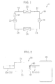
- FIG. 1 is a schematic diagram showing a configuration of a refrigerant circuit of a refrigerating apparatus in accordance with Embodiment 1.
- FIG. 2 is a schematic diagram showing a configuration of an expansion type muffler in accordance with Embodiment 1.
- FIG. 3 is a schematic diagram showing a configuration of a refrigerant circuit of a refrigerating apparatus in accordance with Embodiment 2.
- FIG. 4 FIG. 4 is a schematic diagram showing a configuration of an expansion type muffler in accordance with Embodiment 2.
- FIG. 5 FIG.
- FIG. 5 is a schematic diagram showing a configuration of a refrigerant circuit of a refrigerating apparatus in accordance with Embodiment 3.
- FIG. 6 is a schematic diagram showing a configuration of a branch pipe type muffler.
- FIG. 7 is a schematic diagram showing a configuration of an interference type muffler.
- FIG. 8 is a schematic perspective view of an expansion type muffler in a spiral shape.
- FIG. 9 is a schematic diagram showing a configuration of a refrigerant circuit switchable between a cooling operation and a heating operation.
- a refrigerating apparatus in accordance with Embodiment 1 composes an air conditioner (1) for indoor air conditioning.
- the refrigerating apparatus (1) includes a refrigerant circuit (10) performing a vapor compression refrigeration cycle by circulating refrigerant.
- the refrigerant circuit (10) is filled with carbon dioxide as the refrigerant.
- the refrigeration cycle in which the refrigerant is compressed to over its critical pressure is performed in the refrigerant circuit (10).
- a compressor (20), a radiator (21), an expander (22), and an evaporator (23) are connected to one another by means of refrigerant pipes (11, 12, 13, 14).
- a discharge pipe (11) is connected to the discharge side of the compressor (20.
- the other end of the discharge pipe (11) is connected to one end of the radiator (21).
- the other end of the radiator (21) is connected to one end of an inflow pipe (12).
- the other end of the inflow pipe (12) is connected to the inflow side of the expander (22).
- the outflow side of the expander (22) is connected to one end of an outflow pipe (13).
- the other end of the outflow pipe (13) is connected to one end of the evaporator (23).
- the other end of the evaporator (23) is connected to one end of a suction pipe (14).
- the other end of the suction pipe (14) is connected to the suction side of the compressor (20).
- the compressor (20) is of positive displacement type.
- the compressor (20) accommodates in its casing a rotary compression mechanism.
- the compression mechanism of the compressor (20) compresses gas refrigerant up to a pressure over its critical pressure.
- the radiator (21) is disposed in an indoor space, for example, and is composed of a fin-and-tube type heat exchanger. In the radiator (21), heat is radiated from the high-temperature high-pressure refrigerant indoors.
- the expander (22) is of positive displacement type.
- the expander (22) accommodates in its casing a rotary expansion mechanism.
- the expansion mechanism of the expander (22) reduces the pressure of the high-pressure refrigerant to allow it to be in a gas-liquid two-phase state.
- the evaporator (23) is disposed in an outdoor space, for example, and is composed of a fin-and-tube heat exchanger. In the evaporator (23), the low-pressure liquid refrigerant absorbs heat from the outdoor air to be evaporated
- an expansion type muffler (30) is provided in the refrigerant circuit (10).
- the expansion type muffler (30) is mounted to the inflow pipe (12) on the inflow side of the expander (22).
- the expansion type muffler (30) includes a hollow cylindrical casing (31), in which a cylindrical expansion passage (32) is formed.
- the expansion passage (32) includes an opening part at one end thereof to which a refrigerant inflow pipe (12a) is connected, and an opening part at the other end thereof to which a refrigerant outflow pipe (12b) is connected.
- each inner diameter of the refrigerant inflow pipe (12a) and the refrigerant outflow pipe (12b) is set at approximately 10 mm, and the inner diameter of the casing (31) is set at approximately 30 mm.
- the inner diameter of the casing (31) is approximately three times as large as each inner diameter of the refrigerant pipes (12a, 12b) connected to the respective ends of the casing (31).
- the channel length 1 of the expansion passage (32) is set at approximately 70 cm.
- the channel length 1 of the expansion passage (32) may be designed according to the sonic speed of the refrigerant which can be obtained from the property and driving condition of the refrigerant flowing in the expansion passage (32) and the frequency of the pressure pulsation which can be obtained from the rotating speed of the expansion mechanism of the expander (22).
- the expansion type muffler (30) includes a partition plate (60) at the opening part of the expansion passage (32) on the side of the expander (22).
- the partition plate (60) has a circular opening (61) having a diameter smaller than the inner diameter of the refrigerant outflow pipe (12b), and is fitted in the refrigerant outflow pipe (12b).
- the partition plate (60) functions as an orifice for preventing resonance of the pressure wave from the expander (22) accompanied by the operation of the expander (22).
- the high-pressure refrigerant is reduced in pressure to be low-pressure refrigerant in a gas-liquid two-phase state.
- the refrigerant having been reduced in pressure in the expander (22) flows out into the outflow pipe (13).
- the refrigerant flowing in the outflow pipe (13) flows into the evaporator (23).
- the refrigerant absorbs heat from the outdoor air to be evaporated.
- the gas refrigerant having been evaporated in the evaporator (23) flows into the suction pipe (14), and is then sucked into the compressor (20).
- the compression mechanism of the compressor (20) the refrigerant is compressed again to over its critical pressure.
- refrigerant compression by the compressor (20) may accompany variation in pressure of the refrigerant flowing in the refrigerant circuit (10), which can cause pressure pulsation of the refrigerant in any of the refrigerant pipes (11, 12, 13, 14).
- the inflow pipe (12) on the inflow side of the expander (22) the refrigerant at a comparatively high density flows, and therefore, large pressure pulsation is liable to be caused.
- the expansion type muffler (30) is provided to minimize the pressure pulsation of the refrigerant on the inflow side of the expander (22).
- the high-pressure refrigerant having radiated heat in the radiator (21) flows into the expansion type muffler (30).
- the expansion passage (32) a wave by the pressure variation of the refrigerant receives interference to mitigate the pressure variation of the refrigerant.
- the pressure pulsation of the refrigerant on the inflow side of the expander (22) is reduced.
- a traveling wave of sound progresses from the inflow side of the expander (22) toward the expansion type muffler (30).
- this traveling wave is reflected by the opening part of the expansion passage (32), and accordingly, the reflected wave from the expansion passage (32) toward the expander (22) is readily produced. Resonance of the traveling wave and the reflected wave may generate noise in the refrigerant outflow pipe (12b).
- the partition plate (60) is provided at the opening part of the expansion passage (32) on the side of the expander (22) in the present embodiment. With the partition plate (60) provided, the reflected wave from the expansion type muffler (30) toward the expander (22) is not produced to suppress resonance in the refrigerant outflow pipe (12b).
- Embodiment 1 the expansion type muffler (30) is provided on the inflow side of the expander (22). This can reduce the pressure pulsation of the refrigerant on the inflow side of the expander (22) effectively, while the muffler is simplified. In consequence, in the present invention, cost reduction of the muffler can be contemplated when compared with the conventional accumulator. Such the simplified configuration of the muffler can facilitate the maintenance of the muffler (30).
- the carbon dioxide is compressed to over its critical pressure in the refrigerant circuit (10). This lowers the flow rate of the refrigerant flowing in the expansion type muffler (30). By this lowering, the channel length 1 of the expansion passage (32) can be shortened. Thus, the expansion type muffler (30) can be reduced in size.
- the partition plate (60) serving as an orifice is provided at the opening part of the expansion passage (32) on the side of the expander (22). This can prevent resonance from causing in the refrigerant pipe between the expansion type muffler (30) and the expander (22) (refrigerant outflow pipe (12b)). Hence, noise generated due to the resonance can be avoided.
- Embodiment 2 OF THE INVENTION>
- the same expansion type muffler (30) as that in Embodiment 1 is provided to the outflow pipe (13) on the outflow side of the expander (22) (between a refrigerant inflow pipe (13a) and a refrigerant outflow pipe (13b)).
- this refrigerant circuit (10) the high-pressure refrigerant at a pressure over its critical pressure is reduced in pressure in the expander (22) to be in a gas-liquid two-phase state. Thereafter, the refrigerant in the gas-liquid two-phase state flows into the expansion type muffler (30).
- the pressure pulsation of the refrigerant on the outflow side of the expander (22) can be reduced.
- the sonic speed of the refrigerant flowing in the expansion passage (32) can be reduced further when compared with, for example, that of gas refrigerant. Accordingly, the channel length 1 of the expansion passage (32) can be further shortened, thereby enabling contemplation of reduction in size of the expansion type muffler (30).
- the partition plate (60) is provided at the opening part of the expansion passage (32) on the side of the expander (22) (the refrigerant inflow pipe (13a)). This can prevent the aforementioned resonance from being caused in the refrigerant inflow pipe (13a).
- an expansion valve (24) is provided between the radiator (21) and the expander (22).
- the expansion valve (24) serves as pressure reducing means for allowing the high-pressure refrigerant having radiated heat in the radiator (21) to be in a gas-liquid two-phase state by reducing its pressure.
- the same expansion type muffler (30) as that in above embodiments is provided between the outflow side of the pressure reducing valve (24) and the inflow side of the expander (22).
- Embodiment 3 similarly to the case in Embodiment 2, the refrigerant in the gas-liquid two-phase state is allowed to flow into the expansion type muffler (30). This lowers the flow rate of the refrigerant flowing in the expansion passage (32) to lead to shortening of the length of the expansion passage (32).
- the expansion type muffler (30) is provided on the inflow side or outflow side of the expander (22).
- a branch pipe type muffler (40) shown in FIG. 6 or an interference type muffler (50) shown in FIG. 7 may be employed.
- the branch type muffler (40) shown in FIG. 6 includes a branch pipe (41) branching from a refrigerant pipe (12, 13) on the inflow side or outflow side of the expander (22), and having a closed distal end.
- the branch pipe type muffler (40) interference in pressure variation is allowed to be caused between the refrigerant flowing in the branch pipe (41) branching from the refrigerant pipe (12, 13) and the refrigerant having been reflected by the closed end of the branch pipe (41) to thus reduce the pressure pulsation of the refrigerant.
- the interference type muffler (50) shown in FIG. 7 includes an interference pipe (51) branching from a refrigerant pipe (12, 13) on the inflow side or outflow side of the expander (22), and interflowing again with refrigerant pipe (12, 13).
- interference in pressure variation is allowed to be caused between the refrigerant flowing in the refrigerant pipe (12, 13) and the refrigerant flowing in the interference pipe (51) to reduce the pressure pulsation of the refrigerant.
- Each of the mufflers (40, 50) has a device configuration simpler than the conventional accumulator, thereby enabling contemplation of cost reduction and maintenance facilitation of the mufflers.
- the expansion passage (32) may be formed in a spiral or coil shape, for example.
- the spiral expansion passage (32) can lead to a compact design of the expansion type muffler (30) with the channel length of the expansion passage (32) secured to some extent.
- a four-way switching valve (25) and a bridge circuit (26) including four check valves may be provided, as shown in FIG. 9 , to make the air conditioner (1) switchable between a cooling operation and a heating operation.
- provision of any of the mufflers (30, 40, 50) on the inflow side or outflow side of the expander (22) can reduce the pressure pulsation of the refrigerant on the inflow side or outflow side of the expander (22) during each operation.
- carbon dioxide is used as the refrigerant in the refrigerant circuit (10) for performing the refrigeration cycle in which the carbon dioxide is compressed to over its critical pressure.
- the refrigerant circuit (10) may use another refrigerant, such as R410A or the like. In this case, the refrigerant may not be necessarily compressed to over its critical pressure.
- the compression mechanism of the compressor (20) and the expansion mechanism of the expander (22) may be connected to each other by means of a rotary shaft to compose a generally-called single shaft expander-compressor unit.
- the present invention is useful in measures for reducing the pressure pulsation of refrigerant in a refrigerating apparatus performing a vapor compression refrigeration cycle by circulating the refrigerant.
Landscapes
- Engineering & Computer Science (AREA)
- Physics & Mathematics (AREA)
- Mechanical Engineering (AREA)
- Thermal Sciences (AREA)
- General Engineering & Computer Science (AREA)
- Applications Or Details Of Rotary Compressors (AREA)
- Pipe Accessories (AREA)
Abstract
Description
- The present invention relates to a refrigerating apparatus performing a vapor compression refrigeration cycle by circulating refrigerant, and particularly relates to a measure to reduce pressure pulsation of the refrigerant flowing in a refrigerant circuit.
- Conventionally, refrigerating apparatuses including a refrigerant circuit performing a vapor compression refrigeration cycle have been known.
- For example,
Patent Document 1 discloses a refrigerating apparatus using carbon dioxide as the refrigerant. A compressor, a radiator, a positive displacement type expander, and an evaporator are connected to the refrigerant circuit of this refrigerating apparatus. In the compressor, the refrigerant is compressed to over its critical pressure. The refrigerant discharged from the compressor radiates heat in the radiator, and is expanded in the expander. Thereafter, the refrigerant is evaporated in the evaporator, and is then sucked into the compressor to be compressed again. For example, in a heating operation of this refrigerating apparatus, heat released from the radiator heats an indoor room. - In the expansion mechanism of the expander, a refrigerant expansion operation is performed in such a manner that the piston revolves to increase the volume of the expansion chamber. The refrigerant on the inflow side and outflow side of the expander becomes comparatively high in density. Therefore, the expansion operation by the expander accompanies variation in pressure of the refrigerant on the inflow side and outflow side of the expander to cause large pressure pulsation of the refrigerant. The pressure pulsation of the refrigerant may cause noise generation or malfunction of instruments connected to the refrigerant pipes.
- To tackle this problem, Patent Document 2 proposes a refrigerating apparatus in which a pulsation absorbing accumulator is provided on the inflow side of the expander for reducing the pressure pulsation of the refrigerant. This accumulator includes a sealed container housing a bag-shaped membrane. Inside the membrane, a high-pressure nitrogen gas is encapsulated. When the pressure of the refrigerant flowing, for example, on the inflow side of the expander is increased, the membrane contracts to increase the effective volume of the sealed container. As a result, the pressure of the refrigerant lowers to mitigate and absorb the pressure pulsation of the refrigerant.
Patent Document 1: Japanese Unexamined Patent Application Publication2000-234814
Patent Document 2: Japanese Unexamined Patent Application Publication2004-190938 - However, the accumulator disclosed in Patent Document 2 necessitates the membrane to make the device configuration comparatively complicated, thereby shortening its lifetime and increasing its cost.
- The present invention has been made in view of the foregoing, and its objective is to reduce, in a refrigerating apparatus performing a vapor compression refrigeration cycle, the pressure pulsation of refrigerant on the inflow side or outflow side of an expander by a comparatively simple device configuration.
- A first aspect of the present invention is directed to a refrigerating apparatus including a refrigerant circuit (10) to which a compressor (20) and a positive displacement type expander (22) are connected and which performs a refrigeration cycle by circulating refrigerant. The refrigerating apparatus includes any one of an expansion type muffler (30), a branch pipe type muffler (40), and an interference type muffler (50) on an inflow side or outflow side of the expander (22).
- In the first aspect, the compressor (20) and the expander (22) are provided in the refrigerant circuit (10). In the refrigerant circuit (10), the refrigerant is compressed in the compressor (20), while being expanded in the expander (22), thereby performing the vapor compression refrigeration cycle. In the present aspect, the muffler (30, 40, 50) is provided on the inflow side or outflow side of the expander (22). This muffler is of any one of expansion type, branch pipe type, and interference type. When the refrigerant flows in the muffler (30, 40, 50), the pressure variation of the refrigerant is suppressed to reduce the pressure pulsation of the refrigerant.
- Referring to a second aspect of the present invention, in the first aspect, the refrigerant circuit (10) uses carbon dioxide as the refrigerant for performing the refrigeration cycle, in which the compressor (20) compresses the refrigerant to over its critical pressure.
- In the second aspect, carbon dioxide is filled in the refrigerant circuit (10) as the refrigerant. In the refrigerant circuit (10), the refrigeration cycle is performed in which the compressor compresses the refrigerant to over its critical pressure. When the refrigeration cycle in which carbon dioxide is compressed to over its critical pressure is performed, the refrigerant flowing on the inflow side and outflow side of the expander (22) becomes comparatively low in sonic speed. The lower the sonic speed of the refrigerant of which the sound is to be muffled is, the more the muffler (30, 40, 50) of expansion type, branch pipe type, or interference type according to the present invention can be reduced in size. Accordingly, in this aspect, the pressure pulsation of the refrigerant can be reduced effectively, while size reduction of the muffler (30, 40, 50) can be contemplated.
- Referring to a third aspect of the present invention, in the first or second aspect, the refrigerant circuit (10) includes pressure reducing means (24) for allowing high-pressure refrigerant to be in a gas-liquid two-phase state by reducing its pressure, and the muffler (30, 40, 50) is provided between the outflow side of the pressure reducing means (24) and the inflow side of the expander (22).
- In the third aspect, the pressure reducing means (24) is provided in the refrigerant circuit (10). When the refrigerant passes through the pressure reducing means (24), the high-pressure refrigerant having been compressed in the compressor (20) is reduced in pressure to be in a gas-liquid two-phase state. This refrigerant in the gas-liquid two-phase state flows into the muffler (30, 40, 50). The refrigerant in the gas-liquid two-phase state flowing in the muffler (30, 40, 50) is further lower in sonic speed than, for example, refrigerant in a gas state. In consequence, in the present aspect, the pressure pulsation of the refrigerant can be reduced further effectively, while size reduction of the muffler (30, 40, 50) can be contemplated.
- Referring to a fourth aspect of the present invention, in the first or second aspect, the expander (22) allows high-pressure refrigerant to be in a gas-liquid two-phase state by reducing its pressure, and the muffler (30, 40, 50) is provided on the outflow side of the expander (22).
- In the fourth aspect, the refrigerant having been reduced in pressure in the expander (22) to be in the gas-liquid two-phase state flows into the muffler (30, 40, 50). Accordingly, in the present aspect, similarly to the case in the third aspect, the sonic speed of the refrigerant flowing in the muffler (30, 40, 50) becomes low to lead to size reduction of the muffler (30, 40, 50).
- Referring to a fifth aspect of the present invention, in any one of the first to fourth aspects, the refrigerating apparatus further includes: an expansion type muffler (30) including a expansion passage (32) including at the respective ends thereof opening parts to which refrigerant pipes are connected, the expansion passage (32) having a diameter larger than each of the refrigerant pipes, and a partition plate (60) including an opening (61) having a diameter smaller than an inner diameter of a refrigerant pipe at an opening part of the expansion passage (32) on the side of the expander (22).
- In the fifth aspect, the expansion type muffler (30) is provided on the inflow side or outflow side of the expander (22). The use of the expansion type muffler (30) may cause resonance of a pressure wave generated in the expander (22) to invite noise generation in a refrigerant pipe connecting the expander (22) and the muffler (30). Specifically, the refrigerant expansion operation by the expander (22) allows a traveling wave of sound to progress from the expander (22) toward the muffler (30), so that this pressure wave enters the expansion passage (32). At the opening part on the inflow side of the expansion passage (32), the traveling wave of the sound is readily reflected, which means that the reflected wave is liable to progress from the muffler (30) toward the expander (22). For this reason, the traveling wave of the sound from the expander (22) and the reflected wave from the muffler (30) resonate with each other in the refrigerant pipe between the expander (22) and the muffler (30), thereby readily generating noise. To tackle this problem, in the present aspect, the partition plate (60) is provided at the opening part of the expansion passage (32) on the side of the expander (22). The partition plate (60) has the opening smaller in diameter than the refrigerant pipe to function as a generally-called orifice at the opening part of the expansion passage (32). As a result, in the present aspect, the partition plate (60) can prevent generation of the reflected wave from the expansion passage (32) toward the expander (22) to prevent resonance in the refrigerant pipe between the expander (22) and the muffler (30).
- Referring to a sixth aspect of the present invention, in any one of the first to fourth aspects, the refrigerating apparatus further includes: an expansion type muffler (30) including a expansion passage (32) including at the respective ends thereof opening parts to which refrigerant pipes are connected, the expansion passage (32) having a diameter larger than each of the refrigerant pipes, wherein the expansion passage (32) is formed in a spiral shape.
- In the sixth aspect, the expansion passage (32) of the expansion type muffler (30) is formed in a spiral shape. Accordingly, in the present aspect, the muffler (30) can be reduced in size with the length of the expansion passage (32) sufficiently secured.
- In the present invention, the muffler (30, 40, 50) of expansion type, branch pipe type, or interference type is provided on the inflow side or outflow side of the expander (22) to reduce the pressure pulsation of the refrigerant. The mufflers (30, 40, 50) of these types have a device configuration simpler than, for example, the accumulate in Patent Document 2, thereby enabling contemplation of a low cost muffler. Such the simple device configuration facilitates the maintenance of the muffler (30, 40, 50).
- Particularly, in the second aspect of the present invention, the muffler (30, 40, 50) is applied to the refrigerant circuit (10) in which carbon dioxide is compressed to over its critical pressure. The refrigeration cycle in which the refrigerant is compressed to over its critical pressure lowers comparatively the sonic speed of the refrigerant flowing in the muffler (30, 40, 50), thereby leading to a compact design of the muffler (30, 40, 50).
- Further, in the third and fourth aspects of the present invention, the refrigerant in the gas-liquid two-phase state is allowed to flow into the muffler (30, 40, 50). The flow rate of the refrigerant in the gas-liquid two-phase state flowing in the muffler (30, 40, 50) lowers further to lead to a further compact design of the muffler (30, 40, 50).
- In the fifth aspect of the present invention, the partition plate (60) serving as an orifice is provided at the opening part of the expansion passage (32) on the side of the expander (22) in the expansion type muffler (30). This prevents resonance from causing in the refrigerant pipe between the muffler (30) and the expander (22). As a result, noise generation caused due to the resonance can be suppressed.
- In the sixth aspect of the present invention, the expansion passage (32) is formed in a spiral shape. This can lead to a further compact design of the muffler (30) with the channel length of the expansion passage (32) sufficiently secured.
- [
FIG. 1] FIG. 1 is a schematic diagram showing a configuration of a refrigerant circuit of a refrigerating apparatus in accordance withEmbodiment 1.
[FIG. 2] FIG. 2 is a schematic diagram showing a configuration of an expansion type muffler in accordance withEmbodiment 1.
[FIG. 3] FIG. 3 is a schematic diagram showing a configuration of a refrigerant circuit of a refrigerating apparatus in accordance with Embodiment 2.
[FIG. 4] FIG. 4 is a schematic diagram showing a configuration of an expansion type muffler in accordance with Embodiment 2.
[FIG. 5] FIG. 5 is a schematic diagram showing a configuration of a refrigerant circuit of a refrigerating apparatus in accordance with Embodiment 3.
[FIG. 6] FIG. 6 is a schematic diagram showing a configuration of a branch pipe type muffler.
[FIG. 7] FIG. 7 is a schematic diagram showing a configuration of an interference type muffler.
[FIG. 8] FIG. 8 is a schematic perspective view of an expansion type muffler in a spiral shape.
[FIG. 9] FIG. 9 is a schematic diagram showing a configuration of a refrigerant circuit switchable between a cooling operation and a heating operation. -
- 1
- air conditioner
- 10
- refrigerating apparatus
- 20
- compressor
- 22
- expander
- 24
- expansion valve (pressure reducing means)
- 30
- expansion type muffler (muffler)
- 40
- branch pipe type muffler (muffler)
- 50
- interference type muffler (muffler)
- 60
- partition plate
- Embodiments of the present invention will be described below in detail with reference to the accompanying drawings.
- <
EMBODIMENT 1> - A refrigerating apparatus in accordance with
Embodiment 1 composes an air conditioner (1) for indoor air conditioning. The refrigerating apparatus (1) includes a refrigerant circuit (10) performing a vapor compression refrigeration cycle by circulating refrigerant. The refrigerant circuit (10) is filled with carbon dioxide as the refrigerant. The refrigeration cycle in which the refrigerant is compressed to over its critical pressure is performed in the refrigerant circuit (10). - In the refrigerant circuit (10), a compressor (20), a radiator (21), an expander (22), and an evaporator (23) are connected to one another by means of refrigerant pipes (11, 12, 13, 14). Specifically, to the discharge side of the compressor (20), one end of a discharge pipe (11) is connected. The other end of the discharge pipe (11) is connected to one end of the radiator (21). The other end of the radiator (21) is connected to one end of an inflow pipe (12). The other end of the inflow pipe (12) is connected to the inflow side of the expander (22). The outflow side of the expander (22) is connected to one end of an outflow pipe (13). The other end of the outflow pipe (13) is connected to one end of the evaporator (23). The other end of the evaporator (23) is connected to one end of a suction pipe (14). The other end of the suction pipe (14) is connected to the suction side of the compressor (20).
- The compressor (20) is of positive displacement type. The compressor (20) accommodates in its casing a rotary compression mechanism. The compression mechanism of the compressor (20) compresses gas refrigerant up to a pressure over its critical pressure. The radiator (21) is disposed in an indoor space, for example, and is composed of a fin-and-tube type heat exchanger. In the radiator (21), heat is radiated from the high-temperature high-pressure refrigerant indoors. The expander (22) is of positive displacement type. The expander (22) accommodates in its casing a rotary expansion mechanism. The expansion mechanism of the expander (22) reduces the pressure of the high-pressure refrigerant to allow it to be in a gas-liquid two-phase state. The evaporator (23) is disposed in an outdoor space, for example, and is composed of a fin-and-tube heat exchanger. In the evaporator (23), the low-pressure liquid refrigerant absorbs heat from the outdoor air to be evaporated.
- As one of the significant features of the present invention, an expansion type muffler (30) is provided in the refrigerant circuit (10). The expansion type muffler (30) is mounted to the inflow pipe (12) on the inflow side of the expander (22). As shown in
FIG. 2 , the expansion type muffler (30) includes a hollow cylindrical casing (31), in which a cylindrical expansion passage (32) is formed. The expansion passage (32) includes an opening part at one end thereof to which a refrigerant inflow pipe (12a) is connected, and an opening part at the other end thereof to which a refrigerant outflow pipe (12b) is connected. InEmbodiment 1, each inner diameter of the refrigerant inflow pipe (12a) and the refrigerant outflow pipe (12b) is set at approximately 10 mm, and the inner diameter of the casing (31) is set at approximately 30 mm. Namely, the inner diameter of the casing (31) is approximately three times as large as each inner diameter of the refrigerant pipes (12a, 12b) connected to the respective ends of the casing (31). Thechannel length 1 of the expansion passage (32) is set at approximately 70 cm. Thechannel length 1 of the expansion passage (32) may be designed according to the sonic speed of the refrigerant which can be obtained from the property and driving condition of the refrigerant flowing in the expansion passage (32) and the frequency of the pressure pulsation which can be obtained from the rotating speed of the expansion mechanism of the expander (22). - The expansion type muffler (30) includes a partition plate (60) at the opening part of the expansion passage (32) on the side of the expander (22). The partition plate (60) has a circular opening (61) having a diameter smaller than the inner diameter of the refrigerant outflow pipe (12b), and is fitted in the refrigerant outflow pipe (12b). The partition plate (60) functions as an orifice for preventing resonance of the pressure wave from the expander (22) accompanied by the operation of the expander (22).
- - Operation Behavior -
Basic operation behavior of the air conditioner (1) in accordance withEmbodiment 1 of the present invention will be described next. During the operation of the air conditioner (1), the compression mechanism of the compressor (20) and the expansion mechanism of the expander (22) are driven. In the compression mechanism of the compressor (20), the gas refrigerant is compressed to over its critical pressure. The refrigerant compressed in the compressor (20) is discharged into the discharge pipe (11). The refrigerant flowing in the discharge pipe (11) flows into the radiator (21). In the radiator (21), the refrigerant radiates heat indoors to heat the indoor air. The refrigerant having radiated the heat in the radiator (21) flows into the inflow pipe (12) and the expansion type muffler (30), and flows then into the expander (22). - In the expansion mechanism of the expander (22), the high-pressure refrigerant is reduced in pressure to be low-pressure refrigerant in a gas-liquid two-phase state. The refrigerant having been reduced in pressure in the expander (22) flows out into the outflow pipe (13). The refrigerant flowing in the outflow pipe (13) flows into the evaporator (23). In the evaporator (23), the refrigerant absorbs heat from the outdoor air to be evaporated. The gas refrigerant having been evaporated in the evaporator (23) flows into the suction pipe (14), and is then sucked into the compressor (20). In the compression mechanism of the compressor (20), the refrigerant is compressed again to over its critical pressure.
- - Pressure Pulsation Suppressing Behavior of Muffler -
In the operation of the above-described air conditioner (1), refrigerant compression by the compressor (20) may accompany variation in pressure of the refrigerant flowing in the refrigerant circuit (10), which can cause pressure pulsation of the refrigerant in any of the refrigerant pipes (11, 12, 13, 14). Particularly, in the inflow pipe (12) on the inflow side of the expander (22), the refrigerant at a comparatively high density flows, and therefore, large pressure pulsation is liable to be caused. To tackle this problem, in the air conditioner (1) ofEmbodiment 1, the expansion type muffler (30) is provided to minimize the pressure pulsation of the refrigerant on the inflow side of the expander (22). - Specifically, the high-pressure refrigerant having radiated heat in the radiator (21) flows into the expansion type muffler (30). In the expansion passage (32), a wave by the pressure variation of the refrigerant receives interference to mitigate the pressure variation of the refrigerant. As a result, the pressure pulsation of the refrigerant on the inflow side of the expander (22) is reduced.
- In association with the expansion operation of the expander (22), a traveling wave of sound progresses from the inflow side of the expander (22) toward the expansion type muffler (30). In the case where the partition plate (60) is not provided at the opening part of the expansion passage (32) on the side of the expander (22), this traveling wave is reflected by the opening part of the expansion passage (32), and accordingly, the reflected wave from the expansion passage (32) toward the expander (22) is readily produced. Resonance of the traveling wave and the reflected wave may generate noise in the refrigerant outflow pipe (12b). To tackle this problem, the partition plate (60) is provided at the opening part of the expansion passage (32) on the side of the expander (22) in the present embodiment. With the partition plate (60) provided, the reflected wave from the expansion type muffler (30) toward the expander (22) is not produced to suppress resonance in the refrigerant outflow pipe (12b).
- - Advantages of Embodiment 1 -
InEmbodiment 1, the expansion type muffler (30) is provided on the inflow side of the expander (22). This can reduce the pressure pulsation of the refrigerant on the inflow side of the expander (22) effectively, while the muffler is simplified. In consequence, in the present invention, cost reduction of the muffler can be contemplated when compared with the conventional accumulator. Such the simplified configuration of the muffler can facilitate the maintenance of the muffler (30). - In the present embodiments, the carbon dioxide is compressed to over its critical pressure in the refrigerant circuit (10). This lowers the flow rate of the refrigerant flowing in the expansion type muffler (30). By this lowering, the
channel length 1 of the expansion passage (32) can be shortened. Thus, the expansion type muffler (30) can be reduced in size. - Further in the present embodiment, the partition plate (60) serving as an orifice is provided at the opening part of the expansion passage (32) on the side of the expander (22). This can prevent resonance from causing in the refrigerant pipe between the expansion type muffler (30) and the expander (22) (refrigerant outflow pipe (12b)). Hence, noise generated due to the resonance can be avoided.
- <EMBODIMENT 2 OF THE INVENTION>
In an air conditioner (1) in accordance with Embodiment 2 of the present invention, as shown inFIG. 3 and FIG. 4 , the same expansion type muffler (30) as that inEmbodiment 1 is provided to the outflow pipe (13) on the outflow side of the expander (22) (between a refrigerant inflow pipe (13a) and a refrigerant outflow pipe (13b)). In this refrigerant circuit (10), the high-pressure refrigerant at a pressure over its critical pressure is reduced in pressure in the expander (22) to be in a gas-liquid two-phase state. Thereafter, the refrigerant in the gas-liquid two-phase state flows into the expansion type muffler (30). As a result, in Embodiment 2, the pressure pulsation of the refrigerant on the outflow side of the expander (22) can be reduced. - Further, by allowing the refrigerant in the gas-liquid two-phase state to flow into the expansion type muffler (30), the sonic speed of the refrigerant flowing in the expansion passage (32) can be reduced further when compared with, for example, that of gas refrigerant. Accordingly, the
channel length 1 of the expansion passage (32) can be further shortened, thereby enabling contemplation of reduction in size of the expansion type muffler (30). - In Embodiment 2, the partition plate (60) is provided at the opening part of the expansion passage (32) on the side of the expander (22) (the refrigerant inflow pipe (13a)). This can prevent the aforementioned resonance from being caused in the refrigerant inflow pipe (13a).
- <EMBODIMENT 3>
In an air conditioner (1) in accordance with Embodiment 3 of the present invention, as shown inFIG. 5 , an expansion valve (24) is provided between the radiator (21) and the expander (22). The expansion valve (24) serves as pressure reducing means for allowing the high-pressure refrigerant having radiated heat in the radiator (21) to be in a gas-liquid two-phase state by reducing its pressure. In Embodiment 3, the same expansion type muffler (30) as that in above embodiments is provided between the outflow side of the pressure reducing valve (24) and the inflow side of the expander (22). - In Embodiment 3, similarly to the case in Embodiment 2, the refrigerant in the gas-liquid two-phase state is allowed to flow into the expansion type muffler (30). This lowers the flow rate of the refrigerant flowing in the expansion passage (32) to lead to shortening of the length of the expansion passage (32).
- <OTHER EMBODIMENTS>
Each of the above embodiments may employ any of the following configurations. - In each of the above embodiments, the expansion type muffler (30) is provided on the inflow side or outflow side of the expander (22). Rather than the expansion type muffler (30), a branch pipe type muffler (40) shown in
FIG. 6 or an interference type muffler (50) shown inFIG. 7 may be employed. - Specifically, the branch type muffler (40) shown in
FIG. 6 includes a branch pipe (41) branching from a refrigerant pipe (12, 13) on the inflow side or outflow side of the expander (22), and having a closed distal end. In the branch pipe type muffler (40), interference in pressure variation is allowed to be caused between the refrigerant flowing in the branch pipe (41) branching from the refrigerant pipe (12, 13) and the refrigerant having been reflected by the closed end of the branch pipe (41) to thus reduce the pressure pulsation of the refrigerant. - The interference type muffler (50) shown in
FIG. 7 includes an interference pipe (51) branching from a refrigerant pipe (12, 13) on the inflow side or outflow side of the expander (22), and interflowing again with refrigerant pipe (12, 13). In the interference type muffler (50), interference in pressure variation is allowed to be caused between the refrigerant flowing in the refrigerant pipe (12, 13) and the refrigerant flowing in the interference pipe (51) to reduce the pressure pulsation of the refrigerant. Each of the mufflers (40, 50) has a device configuration simpler than the conventional accumulator, thereby enabling contemplation of cost reduction and maintenance facilitation of the mufflers. - Referring again to the expansion type muffler (30), as shown in
FIG. 8 , the expansion passage (32) may be formed in a spiral or coil shape, for example. The spiral expansion passage (32) can lead to a compact design of the expansion type muffler (30) with the channel length of the expansion passage (32) secured to some extent. - In the refrigerant circuit (10) in each of the above embodiments, a four-way switching valve (25) and a bridge circuit (26) including four check valves may be provided, as shown in
FIG. 9 , to make the air conditioner (1) switchable between a cooling operation and a heating operation. In this refrigerant circuit (10), provision of any of the mufflers (30, 40, 50) on the inflow side or outflow side of the expander (22) can reduce the pressure pulsation of the refrigerant on the inflow side or outflow side of the expander (22) during each operation. - In each of the above embodiments, carbon dioxide is used as the refrigerant in the refrigerant circuit (10) for performing the refrigeration cycle in which the carbon dioxide is compressed to over its critical pressure. The refrigerant circuit (10) may use another refrigerant, such as R410A or the like. In this case, the refrigerant may not be necessarily compressed to over its critical pressure.
- In each of the above embodiments, the compression mechanism of the compressor (20) and the expansion mechanism of the expander (22) may be connected to each other by means of a rotary shaft to compose a generally-called single shaft expander-compressor unit.
- Each of the above embodiments is a mere essentially preferable example, and is not intended to limit the scopes of the present invention, applicable subjects, and uses.
- As described above, the present invention is useful in measures for reducing the pressure pulsation of refrigerant in a refrigerating apparatus performing a vapor compression refrigeration cycle by circulating the refrigerant.
Claims (6)
- A refrigerating apparatus including a refrigerant circuit (10) to which a compressor (20) and a positive displacement type expander (22) are connected and which performs a refrigeration cycle by circulating refrigerant, comprising:any one of an expansion type muffler (30), a branch pipe type muffler (40), and an interference type muffler (50) on an inflow side or outflow side of the expander (22).
- The refrigerating apparatus of claims 1, wherein
the refrigerant circuit (10) uses carbon dioxide as the refrigerant for performing the refrigeration cycle, in which the compressor (20) compresses the refrigerant to over its critical pressure. - The refrigerating apparatus of claim 1 or 2, wherein
the refrigerant circuit (10) includes pressure reducing means (24) for allowing high-pressure refrigerant to be in a gas-liquid two-phase state by reducing its pressure, and
the muffler (30, 40, 50) is provided between the outflow side of the pressure reducing means (24) and the inflow side of the expander (22). - The refrigerating apparatus of claim 1 or 2, wherein
the expander (22) allows high-pressure refrigerant to be in a gas-liquid two-phase state by reducing its pressure, and
the muffler (30, 40, 50) is provided on the outflow side of the expander (22). - The refrigerating apparatus of claim 1 or 2, comprising:an expansion type muffler (30) including a expansion passage (32) including at the respective ends thereof opening parts to which refrigerant pipes are connected, the expansion passage (32) having a diameter larger than each of the refrigerant pipes, anda partition plate (60) including an opening (61) having a diameter smaller than an inner diameter of a refrigerant pipe at an opening part of the expansion passage (32) on the side of the expander (22).
- The refrigerating apparatus of claim 1 or 2, comprising:an expansion type muffler (30) including a expansion passage (32) including at the respective ends thereof opening parts to which refrigerant pipes are connected, the expansion passage (32) having a diameter larger than each of the refrigerant pipes,wherein the expansion passage (32) is formed in a spiral shape.
Applications Claiming Priority (2)
| Application Number | Priority Date | Filing Date | Title |
|---|---|---|---|
| JP2006209708A JP4904970B2 (en) | 2006-08-01 | 2006-08-01 | Refrigeration equipment |
| PCT/JP2007/064737 WO2008015965A1 (en) | 2006-08-01 | 2007-07-27 | Refrigeration device |
Publications (3)
| Publication Number | Publication Date |
|---|---|
| EP2048457A1 true EP2048457A1 (en) | 2009-04-15 |
| EP2048457A4 EP2048457A4 (en) | 2015-03-04 |
| EP2048457B1 EP2048457B1 (en) | 2016-08-31 |
Family
ID=38997145
Family Applications (1)
| Application Number | Title | Priority Date | Filing Date |
|---|---|---|---|
| EP07791431.5A Not-in-force EP2048457B1 (en) | 2006-08-01 | 2007-07-27 | Refrigeration device |
Country Status (3)
| Country | Link |
|---|---|
| EP (1) | EP2048457B1 (en) |
| JP (1) | JP4904970B2 (en) |
| WO (1) | WO2008015965A1 (en) |
Cited By (2)
| Publication number | Priority date | Publication date | Assignee | Title |
|---|---|---|---|---|
| EP3828482A1 (en) * | 2019-11-28 | 2021-06-02 | Daikin Europe N.V. | Heat pump with a muffler |
| EP3848651A1 (en) * | 2020-01-10 | 2021-07-14 | Viessmann Werke GmbH & Co. KG | Thermal device |
Families Citing this family (3)
| Publication number | Priority date | Publication date | Assignee | Title |
|---|---|---|---|---|
| JP2010048466A (en) * | 2008-08-21 | 2010-03-04 | Daikin Ind Ltd | Refrigerating device |
| CN111829152A (en) * | 2020-07-22 | 2020-10-27 | 青岛海尔空调电子有限公司 | Refrigerant rectifier tube and air conditioner indoor unit |
| CN115435492B (en) * | 2022-09-08 | 2025-06-17 | 青岛海尔空调器有限总公司 | A method, device, equipment, storage medium and system for determining muffler parameters |
Family Cites Families (14)
| Publication number | Priority date | Publication date | Assignee | Title |
|---|---|---|---|---|
| JPS54178220U (en) * | 1978-06-07 | 1979-12-17 | ||
| JPS5618496U (en) * | 1979-07-23 | 1981-02-18 | ||
| JPS5660061U (en) * | 1979-10-15 | 1981-05-22 | ||
| JPS5699374U (en) * | 1980-12-22 | 1981-08-05 | ||
| US4878350A (en) * | 1989-03-08 | 1989-11-07 | Air Products And Chemicals, Inc. | Pulsation dampening device for super critical fluid expansion engine, hydraulic engine or pump in cryogenic service |
| JP3435743B2 (en) * | 1993-08-31 | 2003-08-11 | 株式会社日立製作所 | Air conditioner |
| JP3435759B2 (en) * | 1993-10-29 | 2003-08-11 | 株式会社日立製作所 | Air conditioner |
| JP2000234814A (en) | 1999-02-17 | 2000-08-29 | Aisin Seiki Co Ltd | Vapor compression refrigeration equipment |
| JP4075429B2 (en) * | 2002-03-26 | 2008-04-16 | 三菱電機株式会社 | Refrigeration air conditioner |
| JP2004190938A (en) * | 2002-12-11 | 2004-07-08 | Daikin Ind Ltd | Refrigeration equipment |
| JP2004218934A (en) * | 2003-01-15 | 2004-08-05 | Mitsubishi Electric Corp | Expansion type muffler, refrigeration cycle circuit using the same, and method of manufacturing the same |
| JP2005098663A (en) * | 2003-09-02 | 2005-04-14 | Sanyo Electric Co Ltd | Transient critical refrigerant cycle device |
| JP4254532B2 (en) * | 2003-12-26 | 2009-04-15 | ダイキン工業株式会社 | Heat pump type water heater |
| JP4617812B2 (en) * | 2004-09-30 | 2011-01-26 | ダイキン工業株式会社 | Positive displacement expander |
-
2006
- 2006-08-01 JP JP2006209708A patent/JP4904970B2/en not_active Expired - Fee Related
-
2007
- 2007-07-27 WO PCT/JP2007/064737 patent/WO2008015965A1/en not_active Ceased
- 2007-07-27 EP EP07791431.5A patent/EP2048457B1/en not_active Not-in-force
Cited By (2)
| Publication number | Priority date | Publication date | Assignee | Title |
|---|---|---|---|---|
| EP3828482A1 (en) * | 2019-11-28 | 2021-06-02 | Daikin Europe N.V. | Heat pump with a muffler |
| EP3848651A1 (en) * | 2020-01-10 | 2021-07-14 | Viessmann Werke GmbH & Co. KG | Thermal device |
Also Published As
| Publication number | Publication date |
|---|---|
| JP4904970B2 (en) | 2012-03-28 |
| EP2048457A4 (en) | 2015-03-04 |
| WO2008015965A1 (en) | 2008-02-07 |
| EP2048457B1 (en) | 2016-08-31 |
| JP2008039199A (en) | 2008-02-21 |
Similar Documents
| Publication | Publication Date | Title |
|---|---|---|
| JP6311830B2 (en) | Compressor with muffler function | |
| CN104379937B (en) | Hermetic Compressor and Heat Pump Units | |
| CN101416006B (en) | Expansion valve and air conditioner | |
| EP1944562A1 (en) | Air conditioner | |
| JP2009085570A (en) | Silencer for refrigeration cycle | |
| CN101501421B (en) | freezer | |
| EP2048457B1 (en) | Refrigeration device | |
| WO2010109852A1 (en) | Discharge muffler and two-stage compressor with discharge muffler | |
| CN101501419A (en) | Refrigerating device | |
| EP2048456B1 (en) | Refrigeration device | |
| WO2006103886A1 (en) | Refrigerating apparatus | |
| WO2013027237A1 (en) | Two-stage compressor, and heat pump device | |
| KR20100078065A (en) | Multiple muffler and air-conditioning apparatus including it | |
| CN111417783A (en) | Double rotary compressor and refrigeration cycle device | |
| KR101565426B1 (en) | Multi-noise Circuit Breaker and Refrigeration & Air Conditioning Products Including It | |
| JP2011236855A (en) | Two-stage boosting compressor | |
| JP5195497B2 (en) | Rotary fluid machine | |
| JP2010048466A (en) | Refrigerating device | |
| JP2008032344A (en) | Refrigeration equipment | |
| JP2006275035A (en) | Refrigerating device, refrigerator and compressor |
Legal Events
| Date | Code | Title | Description |
|---|---|---|---|
| PUAI | Public reference made under article 153(3) epc to a published international application that has entered the european phase |
Free format text: ORIGINAL CODE: 0009012 |
|
| 17P | Request for examination filed |
Effective date: 20090129 |
|
| AK | Designated contracting states |
Kind code of ref document: A1 Designated state(s): AT BE BG CH CY CZ DE DK EE ES FI FR GB GR HU IE IS IT LI LT LU LV MC MT NL PL PT RO SE SI SK TR |
|
| AX | Request for extension of the european patent |
Extension state: AL BA HR MK RS |
|
| DAX | Request for extension of the european patent (deleted) | ||
| A4 | Supplementary search report drawn up and despatched |
Effective date: 20150203 |
|
| RIC1 | Information provided on ipc code assigned before grant |
Ipc: F25B 13/00 20060101ALN20150128BHEP Ipc: F25B 9/06 20060101AFI20150128BHEP |
|
| REG | Reference to a national code |
Ref country code: DE Ref legal event code: R079 Ref document number: 602007047739 Country of ref document: DE Free format text: PREVIOUS MAIN CLASS: F25B0041000000 Ipc: F25B0009060000 |
|
| GRAP | Despatch of communication of intention to grant a patent |
Free format text: ORIGINAL CODE: EPIDOSNIGR1 |
|
| RIC1 | Information provided on ipc code assigned before grant |
Ipc: F25B 9/06 20060101AFI20160211BHEP Ipc: F25B 13/00 20060101ALN20160211BHEP |
|
| INTG | Intention to grant announced |
Effective date: 20160223 |
|
| GRAS | Grant fee paid |
Free format text: ORIGINAL CODE: EPIDOSNIGR3 |
|
| GRAA | (expected) grant |
Free format text: ORIGINAL CODE: 0009210 |
|
| AK | Designated contracting states |
Kind code of ref document: B1 Designated state(s): AT BE BG CH CY CZ DE DK EE ES FI FR GB GR HU IE IS IT LI LT LU LV MC MT NL PL PT RO SE SI SK TR |
|
| REG | Reference to a national code |
Ref country code: CH Ref legal event code: EP Ref country code: GB Ref legal event code: FG4D |
|
| REG | Reference to a national code |
Ref country code: IE Ref legal event code: FG4D |
|
| REG | Reference to a national code |
Ref country code: DE Ref legal event code: R096 Ref document number: 602007047739 Country of ref document: DE |
|
| REG | Reference to a national code |
Ref country code: AT Ref legal event code: REF Ref document number: 825356 Country of ref document: AT Kind code of ref document: T Effective date: 20161015 |
|
| REG | Reference to a national code |
Ref country code: LT Ref legal event code: MG4D |
|
| REG | Reference to a national code |
Ref country code: NL Ref legal event code: MP Effective date: 20160831 |
|
| REG | Reference to a national code |
Ref country code: AT Ref legal event code: MK05 Ref document number: 825356 Country of ref document: AT Kind code of ref document: T Effective date: 20160831 |
|
| PG25 | Lapsed in a contracting state [announced via postgrant information from national office to epo] |
Ref country code: FI Free format text: LAPSE BECAUSE OF FAILURE TO SUBMIT A TRANSLATION OF THE DESCRIPTION OR TO PAY THE FEE WITHIN THE PRESCRIBED TIME-LIMIT Effective date: 20160831 Ref country code: LT Free format text: LAPSE BECAUSE OF FAILURE TO SUBMIT A TRANSLATION OF THE DESCRIPTION OR TO PAY THE FEE WITHIN THE PRESCRIBED TIME-LIMIT Effective date: 20160831 |
|
| PG25 | Lapsed in a contracting state [announced via postgrant information from national office to epo] |
Ref country code: ES Free format text: LAPSE BECAUSE OF FAILURE TO SUBMIT A TRANSLATION OF THE DESCRIPTION OR TO PAY THE FEE WITHIN THE PRESCRIBED TIME-LIMIT Effective date: 20160831 Ref country code: AT Free format text: LAPSE BECAUSE OF FAILURE TO SUBMIT A TRANSLATION OF THE DESCRIPTION OR TO PAY THE FEE WITHIN THE PRESCRIBED TIME-LIMIT Effective date: 20160831 Ref country code: SE Free format text: LAPSE BECAUSE OF FAILURE TO SUBMIT A TRANSLATION OF THE DESCRIPTION OR TO PAY THE FEE WITHIN THE PRESCRIBED TIME-LIMIT Effective date: 20160831 Ref country code: NL Free format text: LAPSE BECAUSE OF FAILURE TO SUBMIT A TRANSLATION OF THE DESCRIPTION OR TO PAY THE FEE WITHIN THE PRESCRIBED TIME-LIMIT Effective date: 20160831 Ref country code: GR Free format text: LAPSE BECAUSE OF FAILURE TO SUBMIT A TRANSLATION OF THE DESCRIPTION OR TO PAY THE FEE WITHIN THE PRESCRIBED TIME-LIMIT Effective date: 20161201 Ref country code: LV Free format text: LAPSE BECAUSE OF FAILURE TO SUBMIT A TRANSLATION OF THE DESCRIPTION OR TO PAY THE FEE WITHIN THE PRESCRIBED TIME-LIMIT Effective date: 20160831 |
|
| PG25 | Lapsed in a contracting state [announced via postgrant information from national office to epo] |
Ref country code: EE Free format text: LAPSE BECAUSE OF FAILURE TO SUBMIT A TRANSLATION OF THE DESCRIPTION OR TO PAY THE FEE WITHIN THE PRESCRIBED TIME-LIMIT Effective date: 20160831 Ref country code: RO Free format text: LAPSE BECAUSE OF FAILURE TO SUBMIT A TRANSLATION OF THE DESCRIPTION OR TO PAY THE FEE WITHIN THE PRESCRIBED TIME-LIMIT Effective date: 20160831 |
|
| PG25 | Lapsed in a contracting state [announced via postgrant information from national office to epo] |
Ref country code: BG Free format text: LAPSE BECAUSE OF FAILURE TO SUBMIT A TRANSLATION OF THE DESCRIPTION OR TO PAY THE FEE WITHIN THE PRESCRIBED TIME-LIMIT Effective date: 20161130 Ref country code: CZ Free format text: LAPSE BECAUSE OF FAILURE TO SUBMIT A TRANSLATION OF THE DESCRIPTION OR TO PAY THE FEE WITHIN THE PRESCRIBED TIME-LIMIT Effective date: 20160831 Ref country code: DK Free format text: LAPSE BECAUSE OF FAILURE TO SUBMIT A TRANSLATION OF THE DESCRIPTION OR TO PAY THE FEE WITHIN THE PRESCRIBED TIME-LIMIT Effective date: 20160831 Ref country code: SK Free format text: LAPSE BECAUSE OF FAILURE TO SUBMIT A TRANSLATION OF THE DESCRIPTION OR TO PAY THE FEE WITHIN THE PRESCRIBED TIME-LIMIT Effective date: 20160831 Ref country code: BE Free format text: LAPSE BECAUSE OF FAILURE TO SUBMIT A TRANSLATION OF THE DESCRIPTION OR TO PAY THE FEE WITHIN THE PRESCRIBED TIME-LIMIT Effective date: 20160831 Ref country code: PT Free format text: LAPSE BECAUSE OF FAILURE TO SUBMIT A TRANSLATION OF THE DESCRIPTION OR TO PAY THE FEE WITHIN THE PRESCRIBED TIME-LIMIT Effective date: 20170102 Ref country code: PL Free format text: LAPSE BECAUSE OF FAILURE TO SUBMIT A TRANSLATION OF THE DESCRIPTION OR TO PAY THE FEE WITHIN THE PRESCRIBED TIME-LIMIT Effective date: 20160831 |
|
| REG | Reference to a national code |
Ref country code: DE Ref legal event code: R097 Ref document number: 602007047739 Country of ref document: DE |
|
| PG25 | Lapsed in a contracting state [announced via postgrant information from national office to epo] |
Ref country code: IT Free format text: LAPSE BECAUSE OF FAILURE TO SUBMIT A TRANSLATION OF THE DESCRIPTION OR TO PAY THE FEE WITHIN THE PRESCRIBED TIME-LIMIT Effective date: 20160831 |
|
| PLBE | No opposition filed within time limit |
Free format text: ORIGINAL CODE: 0009261 |
|
| STAA | Information on the status of an ep patent application or granted ep patent |
Free format text: STATUS: NO OPPOSITION FILED WITHIN TIME LIMIT |
|
| REG | Reference to a national code |
Ref country code: FR Ref legal event code: PLFP Year of fee payment: 11 |
|
| 26N | No opposition filed |
Effective date: 20170601 |
|
| PG25 | Lapsed in a contracting state [announced via postgrant information from national office to epo] |
Ref country code: SI Free format text: LAPSE BECAUSE OF FAILURE TO SUBMIT A TRANSLATION OF THE DESCRIPTION OR TO PAY THE FEE WITHIN THE PRESCRIBED TIME-LIMIT Effective date: 20160831 |
|
| REG | Reference to a national code |
Ref country code: CH Ref legal event code: PL |
|
| REG | Reference to a national code |
Ref country code: IE Ref legal event code: MM4A |
|
| PG25 | Lapsed in a contracting state [announced via postgrant information from national office to epo] |
Ref country code: CH Free format text: LAPSE BECAUSE OF NON-PAYMENT OF DUE FEES Effective date: 20170731 Ref country code: LI Free format text: LAPSE BECAUSE OF NON-PAYMENT OF DUE FEES Effective date: 20170731 Ref country code: IE Free format text: LAPSE BECAUSE OF NON-PAYMENT OF DUE FEES Effective date: 20170727 |
|
| REG | Reference to a national code |
Ref country code: FR Ref legal event code: PLFP Year of fee payment: 12 |
|
| PG25 | Lapsed in a contracting state [announced via postgrant information from national office to epo] |
Ref country code: LU Free format text: LAPSE BECAUSE OF NON-PAYMENT OF DUE FEES Effective date: 20170727 |
|
| PG25 | Lapsed in a contracting state [announced via postgrant information from national office to epo] |
Ref country code: MT Free format text: LAPSE BECAUSE OF NON-PAYMENT OF DUE FEES Effective date: 20170727 |
|
| PG25 | Lapsed in a contracting state [announced via postgrant information from national office to epo] |
Ref country code: MC Free format text: LAPSE BECAUSE OF FAILURE TO SUBMIT A TRANSLATION OF THE DESCRIPTION OR TO PAY THE FEE WITHIN THE PRESCRIBED TIME-LIMIT Effective date: 20160831 Ref country code: HU Free format text: LAPSE BECAUSE OF FAILURE TO SUBMIT A TRANSLATION OF THE DESCRIPTION OR TO PAY THE FEE WITHIN THE PRESCRIBED TIME-LIMIT; INVALID AB INITIO Effective date: 20070727 |
|
| PG25 | Lapsed in a contracting state [announced via postgrant information from national office to epo] |
Ref country code: CY Free format text: LAPSE BECAUSE OF NON-PAYMENT OF DUE FEES Effective date: 20160831 |
|
| PG25 | Lapsed in a contracting state [announced via postgrant information from national office to epo] |
Ref country code: TR Free format text: LAPSE BECAUSE OF FAILURE TO SUBMIT A TRANSLATION OF THE DESCRIPTION OR TO PAY THE FEE WITHIN THE PRESCRIBED TIME-LIMIT Effective date: 20160831 |
|
| PG25 | Lapsed in a contracting state [announced via postgrant information from national office to epo] |
Ref country code: IS Free format text: LAPSE BECAUSE OF FAILURE TO SUBMIT A TRANSLATION OF THE DESCRIPTION OR TO PAY THE FEE WITHIN THE PRESCRIBED TIME-LIMIT Effective date: 20161231 |
|
| P01 | Opt-out of the competence of the unified patent court (upc) registered |
Effective date: 20230525 |
|
| PGFP | Annual fee paid to national office [announced via postgrant information from national office to epo] |
Ref country code: FR Payment date: 20230608 Year of fee payment: 17 |
|
| PGFP | Annual fee paid to national office [announced via postgrant information from national office to epo] |
Ref country code: GB Payment date: 20230608 Year of fee payment: 17 |
|
| PGFP | Annual fee paid to national office [announced via postgrant information from national office to epo] |
Ref country code: DE Payment date: 20230531 Year of fee payment: 17 |
|
| REG | Reference to a national code |
Ref country code: DE Ref legal event code: R119 Ref document number: 602007047739 Country of ref document: DE |
|
| GBPC | Gb: european patent ceased through non-payment of renewal fee |
Effective date: 20240727 |
|
| PG25 | Lapsed in a contracting state [announced via postgrant information from national office to epo] |
Ref country code: DE Free format text: LAPSE BECAUSE OF NON-PAYMENT OF DUE FEES Effective date: 20250201 |
|
| PG25 | Lapsed in a contracting state [announced via postgrant information from national office to epo] |
Ref country code: FR Free format text: LAPSE BECAUSE OF NON-PAYMENT OF DUE FEES Effective date: 20240731 |
|
| PG25 | Lapsed in a contracting state [announced via postgrant information from national office to epo] |
Ref country code: GB Free format text: LAPSE BECAUSE OF NON-PAYMENT OF DUE FEES Effective date: 20240727 |