EP2048255A1 - Austenitic stainless steel welded joint and austenitic stainless steel welding material - Google Patents
Austenitic stainless steel welded joint and austenitic stainless steel welding material Download PDFInfo
- Publication number
- EP2048255A1 EP2048255A1 EP07791364A EP07791364A EP2048255A1 EP 2048255 A1 EP2048255 A1 EP 2048255A1 EP 07791364 A EP07791364 A EP 07791364A EP 07791364 A EP07791364 A EP 07791364A EP 2048255 A1 EP2048255 A1 EP 2048255A1
- Authority
- EP
- European Patent Office
- Prior art keywords
- content
- austenitic stainless
- stainless steel
- steels
- formula
- Prior art date
- Legal status (The legal status is an assumption and is not a legal conclusion. Google has not performed a legal analysis and makes no representation as to the accuracy of the status listed.)
- Granted
Links
- 229910000963 austenitic stainless steel Inorganic materials 0.000 title claims abstract description 49
- 238000003466 welding Methods 0.000 title claims description 40
- 239000000463 material Substances 0.000 title claims description 22
- 239000012535 impurity Substances 0.000 claims abstract description 13
- 229910052748 manganese Inorganic materials 0.000 claims abstract description 9
- 229910052804 chromium Inorganic materials 0.000 claims abstract description 8
- 229910052759 nickel Inorganic materials 0.000 claims abstract description 8
- 229910052757 nitrogen Inorganic materials 0.000 claims abstract description 8
- 229910052710 silicon Inorganic materials 0.000 claims abstract description 7
- 229910052717 sulfur Inorganic materials 0.000 claims abstract description 7
- 229910052698 phosphorus Inorganic materials 0.000 claims abstract description 6
- 229910052721 tungsten Inorganic materials 0.000 claims description 21
- 229910052750 molybdenum Inorganic materials 0.000 claims description 19
- 229910052758 niobium Inorganic materials 0.000 claims description 12
- 229910052719 titanium Inorganic materials 0.000 claims description 11
- 229910052796 boron Inorganic materials 0.000 claims description 10
- 229910052735 hafnium Inorganic materials 0.000 claims description 10
- 229910052715 tantalum Inorganic materials 0.000 claims description 10
- 229910052720 vanadium Inorganic materials 0.000 claims description 10
- 229910052726 zirconium Inorganic materials 0.000 claims description 10
- 229910000831 Steel Inorganic materials 0.000 abstract description 37
- 239000010959 steel Substances 0.000 abstract description 37
- 230000007797 corrosion Effects 0.000 abstract description 10
- 238000005260 corrosion Methods 0.000 abstract description 10
- 229910052799 carbon Inorganic materials 0.000 abstract description 3
- 238000007711 solidification Methods 0.000 description 42
- 230000008023 solidification Effects 0.000 description 42
- 238000005336 cracking Methods 0.000 description 39
- 239000012071 phase Substances 0.000 description 36
- 230000000694 effects Effects 0.000 description 35
- 229910001220 stainless steel Inorganic materials 0.000 description 27
- 238000012360 testing method Methods 0.000 description 24
- 230000006866 deterioration Effects 0.000 description 21
- 229910001566 austenite Inorganic materials 0.000 description 9
- 238000002425 crystallisation Methods 0.000 description 9
- 230000008025 crystallization Effects 0.000 description 9
- 239000000203 mixture Substances 0.000 description 9
- 238000001556 precipitation Methods 0.000 description 9
- 239000007791 liquid phase Substances 0.000 description 8
- 229910052751 metal Inorganic materials 0.000 description 8
- 239000002184 metal Substances 0.000 description 8
- 239000000126 substance Substances 0.000 description 8
- 230000001965 increasing effect Effects 0.000 description 7
- 229910000859 α-Fe Inorganic materials 0.000 description 7
- 230000015572 biosynthetic process Effects 0.000 description 6
- 230000007423 decrease Effects 0.000 description 6
- 238000000034 method Methods 0.000 description 6
- 238000005728 strengthening Methods 0.000 description 6
- 239000011324 bead Substances 0.000 description 5
- 239000013078 crystal Substances 0.000 description 5
- 230000006872 improvement Effects 0.000 description 5
- 229910000765 intermetallic Inorganic materials 0.000 description 5
- 238000011835 investigation Methods 0.000 description 5
- 229910052802 copper Inorganic materials 0.000 description 4
- 230000008018 melting Effects 0.000 description 4
- 238000002844 melting Methods 0.000 description 4
- 150000001247 metal acetylides Chemical class 0.000 description 4
- 230000003647 oxidation Effects 0.000 description 4
- 238000007254 oxidation reaction Methods 0.000 description 4
- 239000010953 base metal Substances 0.000 description 3
- 230000000052 comparative effect Effects 0.000 description 3
- 239000010935 stainless steel Substances 0.000 description 3
- 230000007246 mechanism Effects 0.000 description 2
- 150000002739 metals Chemical class 0.000 description 2
- 239000002244 precipitate Substances 0.000 description 2
- 230000001105 regulatory effect Effects 0.000 description 2
- 239000000243 solution Substances 0.000 description 2
- -1 M23C6 Chemical class 0.000 description 1
- 229910052779 Neodymium Inorganic materials 0.000 description 1
- 238000005275 alloying Methods 0.000 description 1
- 230000001276 controlling effect Effects 0.000 description 1
- 210000001787 dendrite Anatomy 0.000 description 1
- 230000002542 deteriorative effect Effects 0.000 description 1
- 238000011161 development Methods 0.000 description 1
- 239000012895 dilution Substances 0.000 description 1
- 238000010790 dilution Methods 0.000 description 1
- 230000002708 enhancing effect Effects 0.000 description 1
- 230000005496 eutectics Effects 0.000 description 1
- 238000011156 evaluation Methods 0.000 description 1
- 239000000945 filler Substances 0.000 description 1
- 238000010438 heat treatment Methods 0.000 description 1
- 230000001771 impaired effect Effects 0.000 description 1
- 230000006698 induction Effects 0.000 description 1
- 230000002265 prevention Effects 0.000 description 1
- 230000008569 process Effects 0.000 description 1
- 239000002994 raw material Substances 0.000 description 1
- 230000004044 response Effects 0.000 description 1
- 229920006395 saturated elastomer Polymers 0.000 description 1
- 230000009466 transformation Effects 0.000 description 1
Images

Classifications
-
- C—CHEMISTRY; METALLURGY
- C22—METALLURGY; FERROUS OR NON-FERROUS ALLOYS; TREATMENT OF ALLOYS OR NON-FERROUS METALS
- C22C—ALLOYS
- C22C38/00—Ferrous alloys, e.g. steel alloys
- C22C38/18—Ferrous alloys, e.g. steel alloys containing chromium
- C22C38/40—Ferrous alloys, e.g. steel alloys containing chromium with nickel
- C22C38/58—Ferrous alloys, e.g. steel alloys containing chromium with nickel with more than 1.5% by weight of manganese
-
- C—CHEMISTRY; METALLURGY
- C22—METALLURGY; FERROUS OR NON-FERROUS ALLOYS; TREATMENT OF ALLOYS OR NON-FERROUS METALS
- C22C—ALLOYS
- C22C38/00—Ferrous alloys, e.g. steel alloys
- C22C38/18—Ferrous alloys, e.g. steel alloys containing chromium
- C22C38/40—Ferrous alloys, e.g. steel alloys containing chromium with nickel
- C22C38/50—Ferrous alloys, e.g. steel alloys containing chromium with nickel with titanium or zirconium
-
- B—PERFORMING OPERATIONS; TRANSPORTING
- B23—MACHINE TOOLS; METAL-WORKING NOT OTHERWISE PROVIDED FOR
- B23K—SOLDERING OR UNSOLDERING; WELDING; CLADDING OR PLATING BY SOLDERING OR WELDING; CUTTING BY APPLYING HEAT LOCALLY, e.g. FLAME CUTTING; WORKING BY LASER BEAM
- B23K35/00—Rods, electrodes, materials, or media, for use in soldering, welding, or cutting
- B23K35/22—Rods, electrodes, materials, or media, for use in soldering, welding, or cutting characterised by the composition or nature of the material
- B23K35/24—Selection of soldering or welding materials proper
- B23K35/30—Selection of soldering or welding materials proper with the principal constituent melting at less than 1550 degrees C
- B23K35/3053—Fe as the principal constituent
-
- C—CHEMISTRY; METALLURGY
- C22—METALLURGY; FERROUS OR NON-FERROUS ALLOYS; TREATMENT OF ALLOYS OR NON-FERROUS METALS
- C22C—ALLOYS
- C22C19/00—Alloys based on nickel or cobalt
- C22C19/03—Alloys based on nickel or cobalt based on nickel
- C22C19/05—Alloys based on nickel or cobalt based on nickel with chromium
-
- C—CHEMISTRY; METALLURGY
- C22—METALLURGY; FERROUS OR NON-FERROUS ALLOYS; TREATMENT OF ALLOYS OR NON-FERROUS METALS
- C22C—ALLOYS
- C22C38/00—Ferrous alloys, e.g. steel alloys
- C22C38/002—Ferrous alloys, e.g. steel alloys containing In, Mg, or other elements not provided for in one single group C22C38/001 - C22C38/60
-
- C—CHEMISTRY; METALLURGY
- C22—METALLURGY; FERROUS OR NON-FERROUS ALLOYS; TREATMENT OF ALLOYS OR NON-FERROUS METALS
- C22C—ALLOYS
- C22C38/00—Ferrous alloys, e.g. steel alloys
- C22C38/005—Ferrous alloys, e.g. steel alloys containing rare earths, i.e. Sc, Y, Lanthanides
-
- C—CHEMISTRY; METALLURGY
- C22—METALLURGY; FERROUS OR NON-FERROUS ALLOYS; TREATMENT OF ALLOYS OR NON-FERROUS METALS
- C22C—ALLOYS
- C22C38/00—Ferrous alloys, e.g. steel alloys
- C22C38/02—Ferrous alloys, e.g. steel alloys containing silicon
-
- C—CHEMISTRY; METALLURGY
- C22—METALLURGY; FERROUS OR NON-FERROUS ALLOYS; TREATMENT OF ALLOYS OR NON-FERROUS METALS
- C22C—ALLOYS
- C22C38/00—Ferrous alloys, e.g. steel alloys
- C22C38/04—Ferrous alloys, e.g. steel alloys containing manganese
-
- C—CHEMISTRY; METALLURGY
- C22—METALLURGY; FERROUS OR NON-FERROUS ALLOYS; TREATMENT OF ALLOYS OR NON-FERROUS METALS
- C22C—ALLOYS
- C22C38/00—Ferrous alloys, e.g. steel alloys
- C22C38/18—Ferrous alloys, e.g. steel alloys containing chromium
- C22C38/34—Ferrous alloys, e.g. steel alloys containing chromium with more than 1.5% by weight of silicon
-
- C—CHEMISTRY; METALLURGY
- C22—METALLURGY; FERROUS OR NON-FERROUS ALLOYS; TREATMENT OF ALLOYS OR NON-FERROUS METALS
- C22C—ALLOYS
- C22C38/00—Ferrous alloys, e.g. steel alloys
- C22C38/18—Ferrous alloys, e.g. steel alloys containing chromium
- C22C38/40—Ferrous alloys, e.g. steel alloys containing chromium with nickel
- C22C38/48—Ferrous alloys, e.g. steel alloys containing chromium with nickel with niobium or tantalum
Definitions
- the present invention relates to an austenitic stainless steel welded joint and to an austenitic stainless steel welding material. More specifically, the present invention relates to an austenitic stainless steel welded joint and an austenitic stainless steel welding material, which not only can be widely applied as steel pipes, steel plates and so on in such fields where high-temperature strength and corrosion resistance are required, but also have good welding performance characteristics, in spite of a P content as high as 0.05% or more.
- austenitic stainless steels such as SUS304H, SUS316H, SUS321H, SUS347H, SUS310S and so on, which are prescribed in JIS, have been used.
- Carbide precipitation is effective as a method for improving the high-temperature strength, in particular creep strength of austenitic stainless steels, and therefore the strengthening mechanism by carbides such as M 23 C 6, NbC and so on are in use.
- the Cu phase which finely precipitates during creep as a result of the addition of Cu, is also utilized for increasing the creep strength.
- Patent Document 1 proposes the P-containing austenitic stainless steels.
- Patent Document 1 discloses an austenite stainless steel improved in creep rupture strength by controlling the content of P within a specific range and adjusting the contents of Ti and Nb in response to the content of C.
- the Patent Document 2 discloses an austenitic stainless steel whose creep rupture characteristics are prevented from deteriorating by suppressing the formation of the ferrite phase which is markedly low in resistance to creep deformation compared to the austenite phase, and at the same time by utilizing the precipitation strengthening effect of phosphides through the addition of a specific amount of P.
- one objective of the present invention is to provide a high-P austenitic stainless steel welded joint being comprised of base metals and a weld metal which have excellent weldability, in spite of having a high creep strength and being economical.
- Another objective of the present invention is to provide a high-P austenitic stainless steel welding material having the same characteristics of the said austenitic stainless steel welded joint.
- the present inventors made various investigations in order to ensure austenitic stainless steels, which are high in creep strength and economical and contain P at a high concentration, and also have excellent weldability by preventing weld solidification cracking.
- the said weld solidification cracking occurs when the liquid phase, which exists among dendrites during weld solidification, remains in a filmy form until low temperature regions, and cannot withstand the applied stress.
- the present inventors based on the idea that the crystallization of the very phase crystallizing out after the primary phase, (for example, austenite in the case of solidification in the "FA mode"), would be effective in preventing the said weld solidification cracking, made detailed investigations concerning the crystallization behavior of the phase crystallizing out after the primary phase in various austenitic stainless steel weld metals.
- the inventors came to realize that if the timing of the crystallization of austenite or delta-ferrite crystallizing out after the primary phase crystallization is controlled, so as to be developed earlier and thereby the remaining filmy liquid phase is split in order to divide the direction of the propagation of cracking, the increase in susceptibility to the weld solidification cracking due to an increase in P content, namely the increase of occurrence of the weld solidification cracking, can be prevented not only in the case of "FA mode” but also in the case of "AF mode".
- the present inventors made further detailed investigations by varying the contents of C, Si, Mn, S, Cr, Ni, sol. Al and N in austenitic stainless steels containing P at a level of not less than 0.05%.
- each element symbol represents the content by mass percent of the element concerned.
- the present inventors further made investigations concerning the cases where the above-mentioned austenitic stainless steels further contain Nd, Cu, Mo, W, B, V, Nb, Ti, Ta, Zr, Hf, Co, Ca and Mg in lieu of part of Fe.
- the present invention has been accomplished on the basis of the above-described findings.
- the main points of the present invention are austenitic stainless steel welded joints shown in the following (1) and (2), and austenitic stainless steel welding materials shown in the following (3) and (4).
- An austenitic stainless steel welded joint which comprises by mass percent, C: 0.05 to 0.25%, Si: not more than 2%, Mn: 0.01 to 3%, P: 0.05 to 0.5%, S: not more than 0.03%, Cr: 15 to 30%, Ni: 6 to 55%, sol. Al: 0.001 to 0.1% and N: not more than 0.03%, with the balance being Fe and impurities, and the following formula (1) is satisfied: Cr + 1.5 ⁇ Si + 2 ⁇ P / Ni + 0.31 ⁇ Mn + 22 ⁇ C + 14.2 ⁇ N + 5 ⁇ P ⁇ 1.388
- each element symbol represents the content by mass percent of the element concerned.
- An austenitic stainless steel welding material which comprises by mass percent, C: 0.05 to 0.25%, Si: not more than 2%, Mn: 0.01 to 3%, P: 0.05 to 0.5%, S: not more than 0.03%, Cr: 15 to 30%, Ni: 6 to 55%, sol. Al: 0.001 to 0.1% and N: not more than 0.03%, with the balance being Fe and impurities, and the following formula (1) is satisfied: Cr + 1.5 ⁇ Si + 2 ⁇ P / Ni + 0.31 ⁇ Mn + 22 ⁇ C + 14.2 ⁇ N + 5 ⁇ P ⁇ 1.388
- each element symbol represents the content by mass percent of the element concerned.
- the austenitic stainless steel welded joints of the present invention in spite of their high P content, can be widely applied in such fields, as steel pipes, steel plates and so on, where not only high-temperature strength and corrosion resistance but also weldability is required.
- the austenitic stainless steel welding materials of the present invention are best suited for producing the above-mentioned austenitic stainless steel welded joints.
- Fig. 1 shows the shape of a test specimen used in creep rupture testing in the examples.
- the content of C is set to 0.05 to 0.25%.
- the content of C is preferably more than 0.06% to not more than 0.2%. More preferably, the content of C is 0.07 to 0.15%.
- Si is an element having a deoxidizing effect in the step of melting the austenitic stainless steels and further is effective in increasing oxidation resistance, steam oxidation resistance and so on.
- Si is desirably added at a content level of not less than 0.1%. If the Si content level exceeds 2% however, Si promotes the precipitation of such intermetallic compound phases as the ⁇ phase and also causes a decrease in toughness and ductility due to the deterioration of the microstructural stability at high temperatures. Furthermore, in the case of complete austenite phase solidification, the susceptibility to the weld solidification cracking markedly increases, so that the occurrence of the said weld solidification cracking increases. Therefore, the content of Si is set to not more than 2%. More preferably, the content of Si is not more than 1%.
- Mn is an element effective in preventing hot working brittleness due to the S which is contained as an impurity in the austenitic stainless steels and, it also has a deoxidizing effect in the step of melting the steels. In order to obtain such effects, a content of Mn not less than 0.01% is necessary. However, if the Mn content level exceeds 3%, Mn promotes the precipitation of such intermetallic compound phases as the ⁇ phase and also causes a decrease in toughness and ductility due to the deterioration of the microstructural stability at high temperatures. Therefore, the content of Mn is set to 0.01 to 3%. The content of Mn is more preferably 0.05 to 2% and further more preferably 0.1 to 1.5%.
- the content of P is required to be not less than 0.05%.
- an excessive content of P causes deterioration of creep ductility and, in particular, when the content of P exceeds 0.5%, the deterioration of creep ductility becomes remarkable. Therefore, the content of P is set to 0.05 to 0.5%.
- the content of P is more preferably 0.06 to 0.3% and further more preferably more than 0.08% to not more than 0.2%.
- S is an impurity element coming from raw materials, for example, on the occasion of the melting of the austenitic stainless steels.
- a high content of S causes deterioration of corrosion resistance and also deteriorates the hot workability and weldability; in particular, when the content of S exceeds 0.03%, the deterioration of corrosion resistance, workability and weldability becomes significant. Therefore, the content of S is set to not more than 0.03%. It is desirable that the S content be reduced as low as possible. Therefore, the content of S is more preferably not more than 0.01% and most preferably not more than 0.005%.
- Cr is an important element for ensuring the oxidation resistance, steam oxidation resistance, high-temperature corrosion resistance and so on, and also contributes to increasing the creep strength through formation of Cr-based carbides.
- the Cr content be not less than 15%.
- the content of Cr is set to 15 to 30%. More preferably, the content of Cr is 18 to 28%.
- Ni is an essential element for ensuring a stable austenitic microstructure and the necessary minimum content of Ni is determined by the contents of elements contained in the austenitic stainless steels such as Cr, Mo, W, Nb and the like, which are the ferrite-forming elements, and Mn, C, N and so on, which are the austenite-forming elements.
- the content of Cr it is necessary that the content of Cr be not less than 15% and, if the Ni content is lower than 6% relative to the Cr content, it is difficult to produce a single phase of austenite and, furthermore, the austenitic microstructure becomes unstable during a long period of use at high temperatures and the high-temperature strength and toughness markedly deteriorate due to the precipitation of such brittle phases as the ⁇ phase.
- the content of Ni is set to 6 to 55%.
- the solidification mode becomes the "A mode", namely austenite single phase solidification, the formula (1) given above may not be satisfied in certain cases and, therefore, the content of Ni is preferably 6 to 30%. More preferably, the content of Ni is 8 to 25%.
- Al has a deoxidizing effect on the occasion of the melting of the austenitic stainless steels.
- the content of Al as sol.Al (“acid-soluble Al") be not less than 0.001%.
- the content of Al as sol.Al exceeds 0.1%, the precipitation of such intermetallic compounds as the ⁇ phase is promoted during use at high temperatures, leading to deterioration of toughness, ductility and high-temperature strength. Therefore, the content of sol.Al is set to 0.001 to 0.1%.
- the content of sol.Al is more preferably 0.005 to 0.05% and further more preferably 0.01 to 0.03%.
- the austenitic stainless steel welded joint according to the present invention (1) and the austenitic stainless steel welding material according to the present invention (3) are defined as the ones containing the above-mentioned elements C to N within their respective content ranges, with the balance being Fe and impurities, and at the same time satisfying the said formula (1).
- the austenitic stainless steel welded joint of the present invention (1) and the austenitic stainless steel welding material of the present invention (3) may further selectively contain, according to need, one or more elements of each of the following groups of elements in lieu of part of Fe;
- the first group element Nd is an element having a creep ductility improving effect and in particular is effective in obtaining good creep ductility in the austenitic stainless steels, according to the present invention, which contain P at a level as high as not less than 0.05%.
- the content of Nd is preferably set to not less than 0.001%. However, if the content of Nd exceeds 0.5%, the amounts of inclusions such as oxides and so on increase. Therefore, if Nd is added, the content of Nd is set to not more than 0.5%.
- the content of Nd is preferably 0.001 to 0.5%and more preferably 0.001 to 0.2%. Further more preferably, the content of Nd is not less than 0.005% to less than 0.1%.
- Second group one or more of Cu: not more than 3%, Mo: not more than 5% and W: not more than 10% provided that Mo + (W/2): not more than 5%, B: not more than 0.03%, V: not more than 1.5%, Nb: not more than 1.5%, Ti: not more than 2%, Ta: not more than 8%, Zr: not more than 1%, Hf: not more than 1% and Co: not more than 5%
- Mo, W, B, V, Nb, Ti, Ta, Zr, Hf and Co being elements of the second group, if added, has the effect of enhancing the creep strength. In order to obtain this effect, the said elements may be added to the steels and thereby contained therein.
- the elements, which are in the second group, are now described in detail.
- Cu not more than 3%
- Cu precipitates as the state of a fine Cu phase coherently with the austenitic mother phase during use at high temperatures, producing a marked creep strength improving effect.
- the content of Cu is preferably not less than 0.01%.
- Cu causes a decrease in hot workability, weldability and creep ductility. Therefore, if Cu is added, the content of Cu is set to not more than 3%.
- the content of Cu is preferably 0.01 to 3%.
- the upper limit of the Cu content is more preferably 2.0% and further more preferably 0.9%.
- Mo not more than 5% and W: not more than 10% provided that Mo + (W/2): not more than 5%.
- Mo and W are effective elements to improve the creep strength and high-temperature strength.
- the content of Mo or W, when each is added singly, is preferably not less than 0.05%.
- the total content of Mo + (W/2) is preferably not less than 0.05%.
- Mo and W are added singly at a level exceeding 5% and 10%, respectively, or when Mo and W are added in combination at a level exceeding 5% as expressed in terms of Mo + (W/2), the said effects are saturated and the alloying costs increase and, in addition, the formation of such intermetallic compounds as the ⁇ phase is induced, so the deterioration of microstructural stability and hot workability occurs. Therefore, if Mo and W are added, the contents thereof are set as follows; Mo: not more than 5% and W: not more than 10% provided that Mo + (W/2): not more than 5%.
- the content of Mo is preferably 0.05 to 5% while the content of W is preferably 0.05 to 10% and, when both the elements are combined and added, the total content of Mo + (W/2) is preferably 0.05 to 5%. Since Mo and W are ferrite-forming elements, the contents of each Mo and W is preferably lower than 4% in order to stabilize the austenitic microstructure.
- B not more than 0.03% B exists in carbonitrides and promotes finely dispersed the precipitation of carbonitrides during use at high temperatures, and at the same time, B exists singly at grain boundaries and therefore strengthens grain boundaries and prevents grain boundary sliding. Therefore, B improves the creep strength and high-temperature strength.
- the content of B is preferably set to not less than 0.0005%. However, if the content of B exceeds 0.03%, deterioration of weldability occurs. Therefore, if B is added, the content of B is set to not more than 0.03%.
- the content of B is preferably 0.0005 to 0.03% and more preferably 0.001 to 0.1%. Further more preferably, the content of B is 0.001 to 0.005%.
- V not more than 1.5%
- V is a carbide-forming element and is effective in improving the creep strength and high-temperature strength.
- the content of V is preferably set to not less than 0.02%. However, if the content of V exceeds 1.5%, marked deterioration of mechanical properties such as toughness and so on occurs. Therefore, if V is added, the content of V is set to not more than 1.5%.
- the content of V is preferably 0.02 to 1.5% and more preferably 0.04 to 1%.
- Nb not more than 1.5%
- Nb is a carbide-forming element and is effective in improving the creep strength and high-temperature strength.
- the content of Nb is preferably set to not less than 0.05%. However, if the content of Nb exceeds 1.5%, marked deterioration of mechanical properties such as toughness and so on occurs. Therefore, if Nb is added, the content of Nb is set to not more than 1.5%.
- the content of Nb is preferably 0.05 to 1.5% and more preferably 0.05 to 0.6%.
- Ti is a carbide-forming element and is effective in improving the creep strength and high-temperature strength.
- the content of Ti is preferably set to not less than 0.005%. However, if the content of Ti exceeds 2%, marked deterioration of mechanical properties such as toughness and so on occurs. Therefore, if Ti is added, the content of Ti is set to not more than 2%.
- the content of Ti is preferably 0.005 to 2% and more preferably 0.05 to 1%.
- Ta not more than 8% Ta is also a carbide-forming element and is effective in improving the creep strength and high-temperature strength.
- the content of Ta is preferably set to not less than 0.01%. However, if the content of Ta exceeds 8%, marked deterioration of mechanical properties such as toughness and so on occurs. Therefore, if Ta is added, the content of Ta is set to not more than 8%.
- the content of Ta is preferably 0.01 to 8% and more preferably 0.01 to 7%. Further more preferably, the content of Ta is 0.05 to 6%.
- Zr not more than 1% Zr mainly contributes to grain boundary strengthening and brings about improvements in creep strength.
- the content of Zr is preferably not less than 0.0005%. However, if the content of Zr exceeds 1%, deterioration of mechanical properties and/or weldability occurs. Therefore, if Zr is added, the content of Zr is set to not more than 1%.
- the content of Zr is preferably 0.0005 to 1% and more preferably 0.01 to 0.8%. Further more preferably, the content of Zr is 0.02 to 0.5%.
- Hf not more than 1% Hf also mainly contributes to grain boundary strengthening and brings about improvements in creep strength.
- the content of Hf is preferably not less than 0.0005%. However, if the content of Hf exceeds 1%, deterioration of mechanical properties and/or weldability occurs. Therefore, if Hf is added, the content of Hf is set to not more than 1%.
- the content of Hf is preferably 0.0005 to 1% and more preferably 0.01 to 0.8%. Further more preferably, the content of Hf is 0.02 to 0.5%.
- Co not more than 5%
- Co stabilizes the austenitic microstructure and contributes to improvements in creep strength.
- the content of Co is preferably not less than 0.05%.
- the content of Co is set to not more than 5%.
- the content of Co is preferably 0.05 to 5%.
- the steels of the present invention can contain only one or a combination of two or more of the above-mentioned elements Cu, Mo, W, B, V, Nb, Ti, Ta, Zr, Hf and Co.
- Each of Ca and Mg are elements of the third group and, if added, have the effect of improving hot workability. In order to obtain this effect, the said elements may be added to the steels and thereby contained therein.
- the elements, which are the third group, are now described in detail.
- Ca not more than 0.05% Ca has an effect of improving the hot workability of steels.
- the content of Ca is preferably set to not less than 0.0001%.
- a Ca content which exceeds 0.05% causes a decrease in hot workability due to the formation of oxide type inclusions and also causes deterioration of ductility. Therefore, if Ca is added, the content of Ca is set to not more than 0.05%.
- the content of Ca is preferably 0.0001 to 0.05% and more preferably 0.001 to 0.02%. Further more preferably, the content of Ca is 0.001 to 0.01%.
- Mg not more than 0.05% Mg also has an effect of improving the hot workability of steels.
- the content of Mg is preferably set to not less than 0.0001%.
- a Mg content which exceeds 0.05% causes a decrease in hot workability due to the formation of oxide type inclusions and also causes deterioration of ductility. Therefore, if Mg is added, the content of Mg is set to not more than 0.05%.
- the content of Mg is preferably 0.0001 to 0.05% and more preferably 0.001 to 0.02%. Further more preferably, the content of Mg is 0.001 to 0.01%.
- the steels of the present invention can contain only one or a combination of both of the above-mentioned elements Ca and Mg.
- the austenitic stainless steel welded joint according to the present invention (2) and the austenitic stainless steel welding material according to the present invention (4) are defined as the ones which contain at least one element selected from the above-mentioned first to third groups in lieu of part of Fe in the austenitic stainless steel welded joint according to the present invention (1) and the austenitic stainless steel welding material according to the present invention (3), respectively, and which satisfy the said formula (2).
- the austenitic stainless steel welded joints according to the present inventions (1) and (2) can be produced by various welding methods such as TIG welding, MIG welding and so on.
- the welding materials in order to produce those austenitic stainless steel welded joints, the austenitic stainless steel welding materials according to the present inventions (3) and (4) can be used.
- Austenitic stainless steels 1 to 12 and A to D having the chemical compositions shown in Table 1 were melted using a high-frequency induction vacuum furnace and cast to form ingots.
- the steels 1 to 12 shown in Table 1 are steels having chemical compositions falling within the range regulated by the present invention.
- the steels A to D in Table 1 are steels of comparative examples with chemical compositions out of the range regulated by the present invention.
- the content of P in austenitic stainless steels used for heat exchange in boilers is restricted to not more than 0.040%, as prescribed in JIS G 3463. Therefore, the P content of 0.03% in the steel A shown in Table 1 corresponds to the P content in the ordinary austenitic stainless steels used for heat exchange in boilers.
- Table 1 Steel Chemical composition (% by mass); Balance: Fe and impurities C Si Mn P S Cr Ni sol.Al N Nd Cu Mo W B Nb Ti Ca Mg Value of formula 1 0.08 0.22 0.80 0.10 0.001 18.55 9.08 0.017 0.011 0.055 - - - 0.0040 0.19 - - 0.0002 1.6570 2 0.08 0.24 0.79 0.11 0.001 18.44 9.15 0.015 0.013 - - - 0.0039 0.19 0.20 - - 1.6485 3 0.08 0.34 0.74 0.10 0.001 18.52 10.06 0.023 0.011 - - - 0.0036 0.18 0.46 0.0003 - 1.5780 4 0.08 0.25 0.76 0.11 0.001 18.39 9.03 0.023 0.011 0.110 - - - 0.0038 0.19 - - - 1.6506 5 0.09 0.29 0.75 0.29 0.001 18.31 9.10 0.024 0.012 0.047 -
- Each ingot obtained was hot-forged in the conventional manner and then subjected to solution heat treatment at 1200°C and then processed into restraint weld cracking test specimens with shape of V groove (1.5 mm, 60°) at the butt end and having a thickness of 12 mm, a width of 50 mm and a length of 150 mm, and Trans-Varestraint test specimens having a thickness of 4 mm, a width of 100 mm and a length of 100 mm.
- the thus-obtained restraint weld cracking test specimens were peripherally restraint-welded, and each butt site was subjected to a no filler welding by the TIG welding method under the following conditions: welding current 150 A, welding voltage 12 V, welding speed 10 cm/min; and the bead surface cracking ratio, namely the percentage occurrence of solidification cracks relative to the weld bead length of the restraint weld cracking test specimens, was measured.
- Trans-Varestraint testing was carried out using the said Trans-Varestraint test specimens under the following conditions: welding current 100 A, welding voltage 15 V, welding speed 15 cm/min, added strain 2%; and the maximum crack length was measured.
- the maximum crack length evaluated by the Trans-Varestraint testing of those austenitic stainless steel weld metals, which are in conventional use for heat resisting purposes, is not longer than 1 mm. Therefore, an austenitic stainless steel showing a maximum crack length of not longer than 1 mm as evaluated by the said Trans-Varestraint testing is considered to have good resistance against weld solidification cracking.
- the bead surface cracking ratio was 0, namely no cracking occurred in the weld metal, in the restraint weld cracking testing, and moreover, the maximum crack length in the Trans-Varestraint testing was not longer than 1 mm.
- the said steel A has excellent weldability; however, the creep rupture time thereof was shorter than 1000 hours, hence the steel A is inferior in creep characteristics.
- the austenitic stainless steel welded joints of the present invention can be widely applied as steel pipes, steel plates and so on in such fields where not only high-temperature strength and corrosion resistance but also weldability is required, in spite of high P content thereof.
- the austenitic stainless steel welding materials of the present invention are best suited for producing the above-mentioned austenitic stainless steel welded joints.
Abstract
Description
- The present invention relates to an austenitic stainless steel welded joint and to an austenitic stainless steel welding material. More specifically, the present invention relates to an austenitic stainless steel welded joint and an austenitic stainless steel welding material, which not only can be widely applied as steel pipes, steel plates and so on in such fields where high-temperature strength and corrosion resistance are required, but also have good welding performance characteristics, in spite of a P content as high as 0.05% or more.
- Conventionally, in boilers and chemical plants which are used under high-temperature conditions, austenitic stainless steels, such as SUS304H, SUS316H, SUS321H, SUS347H, SUS310S and so on, which are prescribed in JIS, have been used.
- However, in recent years, the steam conditions in boilers and the like have shifted toward higher temperatures and higher pressure conditions and, accordingly, the requirements imposed on the performance characteristics of the materials to be used have become more severe and, under the said situation, those austenitic stainless steels which have so far been used are considerably insufficient in high-temperature strength; the development of economical steels more improved in high-temperature strength has been desired.
- Carbide precipitation is effective as a method for improving the high-temperature strength, in particular creep strength of austenitic stainless steels, and therefore the strengthening mechanism by carbides such as M23C6, NbC and so on are in use. The Cu phase, which finely precipitates during creep as a result of the addition of Cu, is also utilized for increasing the creep strength.
- However, an increased C content for carbide precipitation results in a deterioration in corrosion resistance, and carbide-forming strengthening elements are all expensive. Further, a large amount of the addition of Cu decreases the hot workability, weldability and creep ductility, so that the contents of the carbide-forming strengthening elements and Cu are restricted.
- On the other hand, it is known that P, which is essentially an impurity element, contributes to the refinement of the M23C6 type carbides and to the improvement of creep strength. Therefore, for example, the Patent Document 1 and the Patent Document 2 propose the P-containing austenitic stainless steels.
- That is to say, the Patent Document 1 discloses an austenite stainless steel improved in creep rupture strength by controlling the content of P within a specific range and adjusting the contents of Ti and Nb in response to the content of C.
- The Patent Document 2 discloses an austenitic stainless steel whose creep rupture characteristics are prevented from deteriorating by suppressing the formation of the ferrite phase which is markedly low in resistance to creep deformation compared to the austenite phase, and at the same time by utilizing the precipitation strengthening effect of phosphides through the addition of a specific amount of P.
-
- Patent Document 1: Japanese Laid-Open Patent Publication No.
62-243742 - Patent Document 2: Japanese Laid-Open Patent Publication No.
03-153847 - The technique which comprises increasing the content of P as disclosed in the above-mentioned Patent Document 1 and Patent Document 2 causes a deterioration of weldability. That is to say, an increased P content, in particular, a large amount of P content which exceeds 0.05%, significantly causes cracking which occurs when the distortion resulting from the solidification shrinkage or thermal shrinkage exceeds the deformability of the weld metal, in particular, in the stage which is close to the end of the weld solidification process and in which a filmy liquid phase is present mainly along the crystal grain boundaries (hereinafter such cracking is referred to as "weld solidification cracking"). Therefore, in particular, such a large amount of P content which exceeds 0.05% is placed under restrictions from the weldability viewpoint; hence, in the case of the austenitic stainless steels disclosed in the Patent Document 1 and the Patent Document 2, the creep strength-improving effect of P cannot be said to be satisfactorily utilized.
- Accordingly, one objective of the present invention is to provide a high-P austenitic stainless steel welded joint being comprised of base metals and a weld metal which have excellent weldability, in spite of having a high creep strength and being economical. Another objective of the present invention is to provide a high-P austenitic stainless steel welding material having the same characteristics of the said austenitic stainless steel welded joint.
- The present inventors made various investigations in order to ensure austenitic stainless steels, which are high in creep strength and economical and contain P at a high concentration, and also have excellent weldability by preventing weld solidification cracking.
- As mentioned above, the said weld solidification cracking occurs when the liquid phase, which exists among dendrites during weld solidification, remains in a filmy form until low temperature regions, and cannot withstand the applied stress.
- An increased P content results in an increase in susceptibility to weld solidification cracking and thus increases the occurrence of weld solidification cracking. This is due to P being markedly concentrated in the liquid phase during solidification and therefore greatly lowers the solidification completion temperature of the liquid phase and thus the liquid phase remains until low temperature regions.
- Therefore, various investigations have been made to reduce the occurrence of the weld solidification cracking due to the content of P which is contained as an impurity element. It is known that the said weld solidification cracking can be suppressed when the chemical composition is balanced so that ferrite solidification may occur in the primary phase, as disclosed, for example, in the Japanese Laid-Open Patent Publication No.
2003-535213 - "Sutenresuko no Yosetsu (Welding of Stainless Steel), First Edition (written by Kazutoshi Nishimoto, Syogo Natsume, Kazuhiro Ogawa and Osa Matsumoto; published in 2001 by Sanpo Publications, Inc.)", pages 87 to 88, describes in detail the mechanisms for preventing the weld solidification cracking utilizing delta-ferrite and explains that the prevention of the weld solidification cracking can be realized by the liquid phase splitting due to transformation from delta-ferrite to austenite in the solidification mode in which the ferrite forms primary crystals, namely in the "FA mode".
- Contrary to the above-cited documents, the present inventors, based on the idea that the crystallization of the very phase crystallizing out after the primary phase, (for example, austenite in the case of solidification in the "FA mode"), would be effective in preventing the said weld solidification cracking, made detailed investigations concerning the crystallization behavior of the phase crystallizing out after the primary phase in various austenitic stainless steel weld metals.
- As a result, it was first revealed that not only when the solidification mode is the above-mentioned "FA mode", in which primary crystals are formed as ferrite, but also when the solidification mode is the "AF mode", in which primary crystals are formed as austenite, the phase crystallizing out after the primary phase is predominantly of the separate eutectic type crystals crystallizing out and growing from the liquid phase central part during weld solidification.
- Thus, the inventors came to realize that if the timing of the crystallization of austenite or delta-ferrite crystallizing out after the primary phase crystallization is controlled, so as to be developed earlier and thereby the remaining filmy liquid phase is split in order to divide the direction of the propagation of cracking, the increase in susceptibility to the weld solidification cracking due to an increase in P content, namely the increase of occurrence of the weld solidification cracking, can be prevented not only in the case of "FA mode" but also in the case of "AF mode".
- When the P content is not less than 0.05%, the influence of P on the solidification mode is considered to be not negligible.
- Therefore, a microsegregation calculation model, making it possible to predict the stainless steel solidification mode was prepared, taking the influence of P into consideration.
- Based on this microsegregation calculation model, various austenitic stainless steels which differ in chemical composition and show either the "FA mode" or "AF mode" solidification mode were prepared and subjected to testing for susceptibility to the weld solidification cracking.
- As a result, it was revealed that it is possible to inhibit the weld solidification cracking, not only in the case of the "FA mode" solidification mode, but also in the case of the "AF mode" solidification mode, if the timing of crystallization of the phase crystallizing out after the primary phase is made earlier, even if the P content is not less than 0.05%.
- Then, the present inventors made further detailed investigations by varying the contents of C, Si, Mn, S, Cr, Ni, sol. Al and N in austenitic stainless steels containing P at a level of not less than 0.05%.
- As a result, it was found that, in the case of austenitic stainless steels which comprise C: 0.05 to 0.25%, Si: not more than 2%, Mn: 0.01 to 3%, P: 0.05 to 0.5%, S: not more than 0.03%, Cr: 15 to 30%, Ni: 6 to 55%, sol. Al: 0.001 to 0.1% and N: not more than 0.03%, with the balance being Fe and impurities, the weld solidification cracking can be surely and stably inhibited when the composition is designed so that the formula (1) given below may be satisfied and the timing of the crystallization of the phase crystallizing out after the primary phase is controlled.
-

In the formula (1), each element symbol represents the content by mass percent of the element concerned. - The present inventors further made investigations concerning the cases where the above-mentioned austenitic stainless steels further contain Nd, Cu, Mo, W, B, V, Nb, Ti, Ta, Zr, Hf, Co, Ca and Mg in lieu of part of Fe.
- As a result, it was revealed that, in the case of austenitic stainless steels containing at least one element selected from the first to third groups given below in lieu of part of Fe, the said weld solidification cracking can be surely and stably inhibited when the composition is designed so that the formula (2) given below may be satisfied and the timing of the crystallization of the phase crystallizing out after the primary phase is controlled.
-
- First group: Nd: not more than 0.5%;
- Second group: one or more of Cu: not more than 3%, Mo: not more than 5% and W: not more than 10% provided that Mo + (W/2): not more than 5%, B: not more than 0.03%, V: not more than 1.5%, Nb: not more than 1.5%, Ti: not more than 2%, Ta: not more than 8%, Zr: not more than 1%, Hf: not more than 1% and Co: not more than 5%; and
- Third group: one or both of Ca: not more than 0.05% and Mg: not more than 0.05%;

In the formula (2), each element symbol represents the content by mass percent of the element concerned. - The present invention has been accomplished on the basis of the above-described findings. The main points of the present invention are austenitic stainless steel welded joints shown in the following (1) and (2), and austenitic stainless steel welding materials shown in the following (3) and (4).
- (1) An austenitic stainless steel welded joint, which comprises by mass percent, C: 0.05 to 0.25%, Si: not more than 2%, Mn: 0.01 to 3%, P: 0.05 to 0.5%, S: not more than 0.03%, Cr: 15 to 30%, Ni: 6 to 55%, sol. Al: 0.001 to 0.1% and N: not more than 0.03%, with the balance being Fe and impurities, and the following formula (1) is satisfied:

In the formula (1), each element symbol represents the content by mass percent of the element concerned. - (2) The austenitic stainless steel welded joint according to the above (1), which further contains, by mass percent, at least one element selected from the first to third groups given below in lieu of part of Fe and, further, the following formula (2) is satisfied:

In the formula (2), each element symbol represents the content by mass percent of the element concerned. - First group: Nd: not more than 0.5%;
- Second group: one or more of Cu: not more than 3%, Mo: not more than 5% and W: not more than 10% provided that Mo + (W/2): not more than 5%, B: not more than 0.03%, V: not more than 1.5%, Nb: not more than 1.5%, Ti: not more than 2%, Ta: not more than 8%, Zr: not more than 1%, Hf: not more than 1% and Co: not more than 5%; and
- Third group: one or both of Ca: not more than 0.05% and Mg: not more than 0.05%.
- (3) An austenitic stainless steel welding material, which comprises by mass percent, C: 0.05 to 0.25%, Si: not more than 2%, Mn: 0.01 to 3%, P: 0.05 to 0.5%, S: not more than 0.03%, Cr: 15 to 30%, Ni: 6 to 55%, sol. Al: 0.001 to 0.1% and N: not more than 0.03%, with the balance being Fe and impurities, and the following formula (1) is satisfied:

In the formula (1), each element symbol represents the content by mass percent of the element concerned. - (4) The austenitic stainless steel welding material according to the above (3), which further contains, by mass percent, at least one element selected from the first to third groups given below in lieu of part of Fe and, further, the following formula (2) is satisfied:

In the formula (2), each element symbol represents the content by mass percent of the element concerned. - First group: Nd: not more than 0.5%;
- Second group: one or more of Cu: not more than 3%, Mo: not more than 5% and W: not more than 10% provided that Mo + (W/2): not more than 5%, B: not more than 0.03%, V: not more than 1.5%, Nb: not more than 1.5%, Ti: not more than 2%, Ta: not more than 8%, Zr: not more than 1%, Hf: not more than 1% and Co: not more than 5%; and
- Third group: one or both of Ca: not more than 0.05% and Mg: not more than 0.05%.
- The above-mentioned inventions (1) and (2) related to the austenitic stainless steel welded joints and the inventions (3) and (4) related to the austenitic stainless steel welding materials are referred to as "the present invention (1)" to "the present invention (4)", respectively, or collectively referred to as "the present invention".
- The austenitic stainless steel welded joints of the present invention, in spite of their high P content, can be widely applied in such fields, as steel pipes, steel plates and so on, where not only high-temperature strength and corrosion resistance but also weldability is required. The austenitic stainless steel welding materials of the present invention are best suited for producing the above-mentioned austenitic stainless steel welded joints.
- [
Fig. 1] Fig. 1 shows the shape of a test specimen used in creep rupture testing in the examples. - In the following, the reasons for restricting the contents of the component elements of the welded joints and welding materials in the present invention are described in detail. In the following description, the symbol "%" for the content of each element means "% by mass".
- C is an important element effective for ensuring the tensile strength and creep strength which is required for use in a high-temperature environment. In the austenitic stainless steels of the present invention, the above-mentioned effects can be produced and the required high-temperature strength can be obtained only when the content of the C is not less than 0.05%. At a C content level which exceeds 0.25%, however, only the amounts of undissolved carbides in the solution heat treated state increase and no further contribution to the improvement in high-temperature strength can be expected; further, toughness and other mechanical properties as well as corrosion resistance may deteriorate. Therefore, the content of C is set to 0.05 to 0.25%. The content of C is preferably more than 0.06% to not more than 0.2%. More preferably, the content of C is 0.07 to 0.15%.
- Si is an element having a deoxidizing effect in the step of melting the austenitic stainless steels and further is effective in increasing oxidation resistance, steam oxidation resistance and so on. When such effects are required, Si is desirably added at a content level of not less than 0.1%. If the Si content level exceeds 2% however, Si promotes the precipitation of such intermetallic compound phases as the σ phase and also causes a decrease in toughness and ductility due to the deterioration of the microstructural stability at high temperatures. Furthermore, in the case of complete austenite phase solidification, the susceptibility to the weld solidification cracking markedly increases, so that the occurrence of the said weld solidification cracking increases. Therefore, the content of Si is set to not more than 2%. More preferably, the content of Si is not more than 1%.
- Mn is an element effective in preventing hot working brittleness due to the S which is contained as an impurity in the austenitic stainless steels and, it also has a deoxidizing effect in the step of melting the steels. In order to obtain such effects, a content of Mn not less than 0.01% is necessary. However, if the Mn content level exceeds 3%, Mn promotes the precipitation of such intermetallic compound phases as the σ phase and also causes a decrease in toughness and ductility due to the deterioration of the microstructural stability at high temperatures. Therefore, the content of Mn is set to 0.01 to 3%. The content of Mn is more preferably 0.05 to 2% and further more preferably 0.1 to 1.5%.
- P is an important element in the present invention. That is to say, for contributing to fine carbide precipitation and improving the creep strength of the austenitic stainless steels of the present invention, the content of P is required to be not less than 0.05%. However, an excessive content of P causes deterioration of creep ductility and, in particular, when the content of P exceeds 0.5%, the deterioration of creep ductility becomes remarkable. Therefore, the content of P is set to 0.05 to 0.5%. The content of P is more preferably 0.06 to 0.3% and further more preferably more than 0.08% to not more than 0.2%.
- S is an impurity element coming from raw materials, for example, on the occasion of the melting of the austenitic stainless steels. A high content of S causes deterioration of corrosion resistance and also deteriorates the hot workability and weldability; in particular, when the content of S exceeds 0.03%, the deterioration of corrosion resistance, workability and weldability becomes significant. Therefore, the content of S is set to not more than 0.03%. It is desirable that the S content be reduced as low as possible. Therefore, the content of S is more preferably not more than 0.01% and most preferably not more than 0.005%.
- Cr is an important element for ensuring the oxidation resistance, steam oxidation resistance, high-temperature corrosion resistance and so on, and also contributes to increasing the creep strength through formation of Cr-based carbides. In order to obtain the above-mentioned effects, it is necessary that the Cr content be not less than 15%. As the content of Cr increases, the corrosion resistance is improved but when the content of Cr exceeds 30%, the austenitic microstructure becomes unstable, readily allowing the formation of such intermetallic compounds as the σ phase or the α-Cr phase, and so the deterioration of toughness and high-temperature strength occurs. Therefore, the content of Cr is set to 15 to 30%. More preferably, the content of Cr is 18 to 28%.
- Ni is an essential element for ensuring a stable austenitic microstructure and the necessary minimum content of Ni is determined by the contents of elements contained in the austenitic stainless steels such as Cr, Mo, W, Nb and the like, which are the ferrite-forming elements, and Mn, C, N and so on, which are the austenite-forming elements. In the present invention, it is necessary that the content of Cr be not less than 15% and, if the Ni content is lower than 6% relative to the Cr content, it is difficult to produce a single phase of austenite and, furthermore, the austenitic microstructure becomes unstable during a long period of use at high temperatures and the high-temperature strength and toughness markedly deteriorate due to the precipitation of such brittle phases as the σ phase. On the other hand, if the Ni content level exceeds 55%, the said effects of Ni arrive at saturation levels and the economic efficiency is impaired. Therefore, the content of Ni is set to 6 to 55%. When the Ni content is high, the solidification mode becomes the "A mode", namely austenite single phase solidification, the formula (1) given above may not be satisfied in certain cases and, therefore, the content of Ni is preferably 6 to 30%. More preferably, the content of Ni is 8 to 25%.
- Al has a deoxidizing effect on the occasion of the melting of the austenitic stainless steels. In order to obtain this effect, it is necessary that the content of Al as sol.Al ("acid-soluble Al") be not less than 0.001%. However, when the content of Al as sol.Al exceeds 0.1%, the precipitation of such intermetallic compounds as the σ phase is promoted during use at high temperatures, leading to deterioration of toughness, ductility and high-temperature strength. Therefore, the content of sol.Al is set to 0.001 to 0.1%. The content of sol.Al is more preferably 0.005 to 0.05% and further more preferably 0.01 to 0.03%.
- A content of N which exceeds 0.03% causes deterioration of hot workability and, therefore, the content of N is set to not more than 0.03%. It is desirable that the N content be reduced as low as possible. Thus, the content of N is more preferably not more than 0.02% and further more preferably not more than 0.015%.
- The value of (Cr + 1.5 × Si + 2 × P)/(Ni + 0.31 × Mn + 22 × C + 14.2 × N + 5 × P): not less than 1.388
When the austenitic stainless steels which comprise the above-mentioned elements C to N within the respective content ranges, with the balance being Fe and impurities have a value of "(Cr + 1.5 × Si + 2 × P)/ (Ni + 0.31 × Mn + 22 × C + 14.2 × N + 5 × P)" which is not less than 1.388, namely satisfy the formula (1), the timing of crystallization of the phase crystallizing out after the primary phase is controlled and the weld solidification cracking can be surely and stably inhibited. - From the reasons mentioned above, the austenitic stainless steel welded joint according to the present invention (1) and the austenitic stainless steel welding material according to the present invention (3) are defined as the ones containing the above-mentioned elements C to N within their respective content ranges, with the balance being Fe and impurities, and at the same time satisfying the said formula (1).
- The austenitic stainless steel welded joint of the present invention (1) and the austenitic stainless steel welding material of the present invention (3) may further selectively contain, according to need, one or more elements of each of the following groups of elements in lieu of part of Fe;
- First group: Nd: not more than 0.5%;
- Second group: one or more of Cu: not more than 3%, Mo: not more than 5% and W: not more than 10% provided that Mo + (W/2): not more than 5%, B: not more than 0.03%, V: not more than 1.5%, Nb: not more than 1.5%, Ti: not more than 2%, Ta: not more than 8%, Zr: not more than 1%, Hf: not more than 1% and Co: not more than 5%; and
- Third group: one or both of Ca: not more than 0.05% and Mg: not more than 0.05%.
That is to say, one or more of the first to third groups of elements may be added, as optional elements, to the above-mentioned steels and thereby contained therein. - The above-mentioned optional elements will be explained below.
- First group: Nd: not more than 0.5%
The first group element Nd is an element having a creep ductility improving effect and in particular is effective in obtaining good creep ductility in the austenitic stainless steels, according to the present invention, which contain P at a level as high as not less than 0.05%. In order to obtain surely the above-mentioned effect, the content of Nd is preferably set to not less than 0.001%. However, if the content of Nd exceeds 0.5%, the amounts of inclusions such as oxides and so on increase. Therefore, if Nd is added, the content of Nd is set to not more than 0.5%. The content of Nd is preferably 0.001 to 0.5%and more preferably 0.001 to 0.2%. Further more preferably, the content of Nd is not less than 0.005% to less than 0.1%. - Second group: one or more of Cu: not more than 3%, Mo: not more than 5% and W: not more than 10% provided that Mo + (W/2): not more than 5%, B: not more than 0.03%, V: not more than 1.5%, Nb: not more than 1.5%, Ti: not more than 2%, Ta: not more than 8%, Zr: not more than 1%, Hf: not more than 1% and Co: not more than 5%
Each of Cu, Mo, W, B, V, Nb, Ti, Ta, Zr, Hf and Co being elements of the second group, if added, has the effect of enhancing the creep strength. In order to obtain this effect, the said elements may be added to the steels and thereby contained therein. The elements, which are in the second group, are now described in detail. - Cu: not more than 3%
Cu precipitates as the state of a fine Cu phase coherently with the austenitic mother phase during use at high temperatures, producing a marked creep strength improving effect. In order to ensure the above-mentioned effect, the content of Cu is preferably not less than 0.01%. However, at a high Cu content level, in particular, at a Cu content level of more than 3%, Cu causes a decrease in hot workability, weldability and creep ductility. Therefore, if Cu is added, the content of Cu is set to not more than 3%. The content of Cu is preferably 0.01 to 3%. The upper limit of the Cu content is more preferably 2.0% and further more preferably 0.9%. - Mo: not more than 5% and W: not more than 10% provided that Mo + (W/2): not more than 5%.
Mo and W are effective elements to improve the creep strength and high-temperature strength. In order to ensure the above-mentioned effects, the content of Mo or W, when each is added singly, is preferably not less than 0.05%. When both the elements are combined and added, the total content of Mo + (W/2) is preferably not less than 0.05%. However, when Mo and W are added singly at a level exceeding 5% and 10%, respectively, or when Mo and W are added in combination at a level exceeding 5% as expressed in terms of Mo + (W/2), the said effects are saturated and the alloying costs increase and, in addition, the formation of such intermetallic compounds as the σ phase is induced, so the deterioration of microstructural stability and hot workability occurs. Therefore, if Mo and W are added, the contents thereof are set as follows; Mo: not more than 5% and W: not more than 10% provided that Mo + (W/2): not more than 5%. When either Mo and W are added singly, the content of Mo is preferably 0.05 to 5% while the content of W is preferably 0.05 to 10% and, when both the elements are combined and added, the total content of Mo + (W/2) is preferably 0.05 to 5%. Since Mo and W are ferrite-forming elements, the contents of each Mo and W is preferably lower than 4% in order to stabilize the austenitic microstructure. - B: not more than 0.03%
B exists in carbonitrides and promotes finely dispersed the precipitation of carbonitrides during use at high temperatures, and at the same time, B exists singly at grain boundaries and therefore strengthens grain boundaries and prevents grain boundary sliding. Therefore, B improves the creep strength and high-temperature strength. In order to ensure the said effects, the content of B is preferably set to not less than 0.0005%. However, if the content of B exceeds 0.03%, deterioration of weldability occurs. Therefore, if B is added, the content of B is set to not more than 0.03%. The content of B is preferably 0.0005 to 0.03% and more preferably 0.001 to 0.1%. Further more preferably, the content of B is 0.001 to 0.005%. - V: not more than 1.5%
V is a carbide-forming element and is effective in improving the creep strength and high-temperature strength. In order to ensure the said effects, the content of V is preferably set to not less than 0.02%. However, if the content of V exceeds 1.5%, marked deterioration of mechanical properties such as toughness and so on occurs. Therefore, if V is added, the content of V is set to not more than 1.5%. The content of V is preferably 0.02 to 1.5% and more preferably 0.04 to 1%. - Nb: not more than 1.5%
Nb is a carbide-forming element and is effective in improving the creep strength and high-temperature strength. In order to ensure the said effects, the content of Nb is preferably set to not less than 0.05%. However, if the content of Nb exceeds 1.5%, marked deterioration of mechanical properties such as toughness and so on occurs. Therefore, if Nb is added, the content of Nb is set to not more than 1.5%. The content of Nb is preferably 0.05 to 1.5% and more preferably 0.05 to 0.6%. - Ti: not more than 2%
Ti is a carbide-forming element and is effective in improving the creep strength and high-temperature strength. In order to ensure the said effects, the content of Ti is preferably set to not less than 0.005%. However, if the content of Ti exceeds 2%, marked deterioration of mechanical properties such as toughness and so on occurs. Therefore, if Ti is added, the content of Ti is set to not more than 2%. The content of Ti is preferably 0.005 to 2% and more preferably 0.05 to 1%. - Ta: not more than 8%
Ta is also a carbide-forming element and is effective in improving the creep strength and high-temperature strength. In order to ensure the said effects, the content of Ta is preferably set to not less than 0.01%. However, if the content of Ta exceeds 8%, marked deterioration of mechanical properties such as toughness and so on occurs. Therefore, if Ta is added, the content of Ta is set to not more than 8%. The content of Ta is preferably 0.01 to 8% and more preferably 0.01 to 7%. Further more preferably, the content of Ta is 0.05 to 6%. - Zr: not more than 1%
Zr mainly contributes to grain boundary strengthening and brings about improvements in creep strength. In order to ensure the said effects, the content of Zr is preferably not less than 0.0005%. However, if the content of Zr exceeds 1%, deterioration of mechanical properties and/or weldability occurs. Therefore, if Zr is added, the content of Zr is set to not more than 1%. The content of Zr is preferably 0.0005 to 1% and more preferably 0.01 to 0.8%. Further more preferably, the content of Zr is 0.02 to 0.5%. - Hf: not more than 1%
Hf also mainly contributes to grain boundary strengthening and brings about improvements in creep strength. In order to ensure the said effects, the content of Hf is preferably not less than 0.0005%. However, if the content of Hf exceeds 1%, deterioration of mechanical properties and/or weldability occurs. Therefore, if Hf is added, the content of Hf is set to not more than 1%. The content of Hf is preferably 0.0005 to 1% and more preferably 0.01 to 0.8%. Further more preferably, the content of Hf is 0.02 to 0.5%. - Co: not more than 5%
Like Ni, Co stabilizes the austenitic microstructure and contributes to improvements in creep strength. In order to ensure the said effects, the content of Co is preferably not less than 0.05%. However, at a Co content level which exceeds 5%, the said effects of Co arrive at saturation levels and the economic efficiency only declines. Therefore, if Co is added, the content of Co is set to not more than 5%. The content of Co is preferably 0.05 to 5%. - The steels of the present invention can contain only one or a combination of two or more of the above-mentioned elements Cu, Mo, W, B, V, Nb, Ti, Ta, Zr, Hf and Co.
- Each of Ca and Mg are elements of the third group and, if added, have the effect of improving hot workability. In order to obtain this effect, the said elements may be added to the steels and thereby contained therein. The elements, which are the third group, are now described in detail.
- Ca: not more than 0.05%
Ca has an effect of improving the hot workability of steels. In order to ensure this effect, the content of Ca is preferably set to not less than 0.0001%. However, a Ca content which exceeds 0.05% causes a decrease in hot workability due to the formation of oxide type inclusions and also causes deterioration of ductility. Therefore, if Ca is added, the content of Ca is set to not more than 0.05%. The content of Ca is preferably 0.0001 to 0.05% and more preferably 0.001 to 0.02%. Further more preferably, the content of Ca is 0.001 to 0.01%. - Mg: not more than 0.05%
Mg also has an effect of improving the hot workability of steels. In order to ensure this effect, the content of Mg is preferably set to not less than 0.0001%. However, a Mg content which exceeds 0.05% causes a decrease in hot workability due to the formation of oxide type inclusions and also causes deterioration of ductility. Therefore, if Mg is added, the content of Mg is set to not more than 0.05%. The content of Mg is preferably 0.0001 to 0.05% and more preferably 0.001 to 0.02%. Further more preferably, the content of Mg is 0.001 to 0.01%. - The steels of the present invention can contain only one or a combination of both of the above-mentioned elements Ca and Mg.
- The value of (Cr + 1.5 × Si + 2 × Nb + Ti + 2 × P)/(Ni + 0.31 × Mn + 22 × C + 14.2 × N + Cu + 5 × P): not less than 1.388
The austenitic stainless steels containing at least one element selected from the above-mentioned first to third groups in lieu of part of Fe in the austenitic stainless steel welded joint according to the present invention (1) and the austenitic stainless steel welding material according to the present invention (3), when they have a value of not less than 1.388 as the value of (Cr + 1.5 × Si + 2 × Nb + Ti + 2 × P)/(Ni + 0.31 × Mn + 22 × C + 14.2 × N + Cu + 5 × P), namely satisfy the formula (2), the timing of the crystallization of the phase crystallizing out after the primary phase can be controlled and the weld solidification cracking can be surely and stably inhibited. - From the reasons mentioned above, the austenitic stainless steel welded joint according to the present invention (2) and the austenitic stainless steel welding material according to the present invention (4) are defined as the ones which contain at least one element selected from the above-mentioned first to third groups in lieu of part of Fe in the austenitic stainless steel welded joint according to the present invention (1) and the austenitic stainless steel welding material according to the present invention (3), respectively, and which satisfy the said formula (2).
- The austenitic stainless steel welded joints according to the present inventions (1) and (2) can be produced by various welding methods such as TIG welding, MIG welding and so on. As for the welding materials, in order to produce those austenitic stainless steel welded joints, the austenitic stainless steel welding materials according to the present inventions (3) and (4) can be used.
- The following examples illustrate the present invention more specifically. These examples are, however, by no means limited to the scope of the present invention.
- Austenitic stainless steels 1 to 12 and A to D having the chemical compositions shown in Table 1 were melted using a high-frequency induction vacuum furnace and cast to form ingots.
- The steels 1 to 12 shown in Table 1 are steels having chemical compositions falling within the range regulated by the present invention. On the other hand, the steels A to D in Table 1 are steels of comparative examples with chemical compositions out of the range regulated by the present invention.
- The content of P in austenitic stainless steels used for heat exchange in boilers is restricted to not more than 0.040%, as prescribed in JIS G 3463. Therefore, the P content of 0.03% in the steel A shown in Table 1 corresponds to the P content in the ordinary austenitic stainless steels used for heat exchange in boilers.
- [Table 1]
Table 1 Steel Chemical composition (% by mass); Balance: Fe and impurities C Si Mn P S Cr Ni sol.Al N Nd Cu Mo W B Nb Ti Ca Mg Value of formula 1 0.08 0.22 0.80 0.10 0.001 18.55 9.08 0.017 0.011 0.055 - - - 0.0040 0.19 - - 0.0002 1.6570 2 0.08 0.24 0.79 0.11 0.001 18.44 9.15 0.015 0.013 - - - - 0.0039 0.19 0.20 - - 1.6485 3 0.08 0.34 0.74 0.10 0.001 18.52 10.06 0.023 0.011 - - - - 0.0036 0.18 0.46 0.0003 - 1.5780 4 0.08 0.25 0.76 0.11 0.001 18.39 9.03 0.023 0.011 0.110 - - - 0.0038 0.19 - - - 1.6506 5 0.09 0.29 0.75 0.29 0.001 18.31 9.10 0.024 0.012 0.047 - - - 0.0036 0.19 0.17 0.0003 0.0002 1.5368 6 0.09 0.24 0.79 0.10 0.001 18.52 9.17 0.022 0.012 0.130 - - - - - 0.19 - - 1.5971 7 0.11 0.20 0.79 0.11 0.001 18.70 9.27 0.036 0.007 - - - - - - - - - 1.5273 8 0.14 0.19 0.78 0.09 0.002 18.23 8.99 0.032 0.005 - - - - - - 0.18 - - 1.4708 9 0.17 0.19 0.77 0.10 0.003 18.52 9.14 0.024 0.005 0.003 - - - - - - - - 1.3883 10 0.12 0.21 0.78 0.10 0.003 18.37 6.07 0.028 0.005 - 1.50 - - - - - - - 1.7133 11 0.17 0.21 0.78 0.10 0.002 18.32 9.06 0.033 0.005 0.006 - 1.98 - - - 0.18 - - 1.3968 12 0.19 0.20 0.77 0.10 0.002 18.39 9.00 0.026 0.005 0.002 - - 1.40 - - 0.58 - - 1.3917 A 0.10 0.19 0.82 *0.03 0.001 18.29 10.07 0.016 0.008 - - - - 0.0033 0.21 - - - 1.4901 B 0.08 0.20 0.81 0.05 0.001 18.42 8.91 0.022 0.009 - 2.99 - - 0.0038 0.50 - - - *1.3871 C 0.10 0.20 0.82 0.29 0.001 18.19 10.28 0.018 0.006 0.035 - - - 0.0034 0.21 0.21 - - *1.3806 D 0.10 0.19 0.81 0.09 0.001 18.35 10.06 0.014 0.008 0.035 3.00 - - 0.0031 0.20 0.20 - - *1.2078 The value of formula for steel 7 is the value of (Cr + 1.5 × Si + 2 × P) / (Ni + 0.31 × Mn + 22 × C + 14.2 × N + 5 × P); for other steels, values of (Cr + 1.5 × Si + 2 × Nb + Ti + 2 × P)/(Ni + 0.31 × Mn + 22 × C + 14.2 × N + Cu + 5 × P) are given. The mark * indicates falling outside the conditions specified by the present invention. - Each ingot obtained was hot-forged in the conventional manner and then subjected to solution heat treatment at 1200°C and then processed into restraint weld cracking test specimens with shape of V groove (1.5 mm, 60°) at the butt end and having a thickness of 12 mm, a width of 50 mm and a length of 150 mm, and Trans-Varestraint test specimens having a thickness of 4 mm, a width of 100 mm and a length of 100 mm.
- The thus-obtained restraint weld cracking test specimens, each made of austenitic stainless steel, were peripherally restraint-welded, and each butt site was subjected to a no filler welding by the TIG welding method under the following conditions: welding current 150 A, welding voltage 12 V, welding speed 10 cm/min; and the bead surface cracking ratio, namely the percentage occurrence of solidification cracks relative to the weld bead length of the restraint weld cracking test specimens, was measured.
- For more detailed evaluation of the susceptibility of each austenitic stainless steel to solidification cracking, Trans-Varestraint testing was carried out using the said Trans-Varestraint test specimens under the following conditions: welding current 100 A, welding voltage 15 V, welding speed 15 cm/min, added strain 2%; and the maximum crack length was measured. The maximum crack length evaluated by the Trans-Varestraint testing of those austenitic stainless steel weld metals, which are in conventional use for heat resisting purposes, is not longer than 1 mm. Therefore, an austenitic stainless steel showing a maximum crack length of not longer than 1 mm as evaluated by the said Trans-Varestraint testing is considered to have good resistance against weld solidification cracking.
- Furthermore, using a welding material (weld wire) with an outside diameter of 1.2 mm produced in advance from each austenitic stainless steel base metal, multilayer welding was carried out by the TIG welding method under these conditions: welding current 165 A, welding voltage 15 V, welding speed 10 cm/min; and test specimens having the dimension shown in
Fig. 1 , were prepared and subjected to creep rupture testing under the conditions of 700°C and 147 MPa, for investigating the creep rupture time of the welded joint. In the case of TIG welding, the chemical composition of the weld metal hardly undergoes dilution, hence remains the same as that of the base metal. - The results of the tests mentioned above are summarized in Table 2, together with the values of the left side member of the said formula (1) or (2). In Table 2, the creep rupture property was evaluated by "×", when the creep rupture time was shorter than 1000 hours, and was evaluated by "○", when the said time was 1000 hours or longer.
- [Table 2]
Table 2 Steel Value of formula Weldability Result of creep rupture testing under conditions of 700°C and 147 MPa Remark Bead surface cracking ratio in restraint weld cracking testing (%) Maximum crack length in Trans-Varestra int testing (mm) 1 1.6570 0 0.63 ○ 2 1.6485 0 0.51 ○ 3 1.5780 0 0.71 ○ 4 1.6506 0 0.58 ○ 5 1.5368 0 0.93 ○ 6 1.5971 0 0.49 ○ Inventive 7 1.5273 0 0.379 ○ examples 8 1.4708 0 0.248 ○ 9 1.3883 0 0.326 ○ 10 1.7133 0 0.397 ○ 11 1.3968 0 0.411 ○ 12 1.3917 0 0.532 ○ *A 1.4901 0 0.42 × *B *1.3871 100 1.01 ○ Comparative *C *1.3806 100 3.96 ○ examples *D *1.2078 100 2.77 ○ The value of formula for steel 7 is the value of (Cr + 1.5 × Si + 2 × P)/(Ni + 0.31 × Mn + 22 × C + 14.2 × N + 5 × P); for other steels, values of (Cr + 1.5 × Si + 2 × Nb + Ti + 2 × P)/(Ni + 0.31 × Mn + 22 × C + 14.2 × N + Cu + 5 × P) are given. The marks "○" and "×" in the column "Result of creep rupture testing" respectively indicate that the rupture time was 1000 hours or longer and that it was shorter than 1000 hours. The mark * indicates falling outside the conditions specified by the present invention. - From Table 2, it is evident that in the case of the steels 1 to 12, falling within the conditions specified by the present invention, the bead surface cracking ratio in the restraint weld cracking testing was 0 (zero), namely no cracking occurred at all in the weld metal and the maximum crack length in Trans-Varestraint testing was not longer than 1 mm. Consequently, the said steels 1 to 12 have excellent weldability, in spite of their high P levels of 0.09 to 0.29%. Furthermore, in the case of the above-mentioned steels 1 to 12, the creep rupture time was 1000 hours or longer; therefore it is evident that they are excellent in creep characteristics.
- On the contrary, the comparative steels A to D falling out of the conditions specified by the present invention were inferior in weldability or creep characteristics.
- That is to say, in the case of steel A, owing to the low P content of 0.03%, the bead surface cracking ratio was 0, namely no cracking occurred in the weld metal, in the restraint weld cracking testing, and moreover, the maximum crack length in the Trans-Varestraint testing was not longer than 1 mm. This means that the said steel A has excellent weldability; however, the creep rupture time thereof was shorter than 1000 hours, hence the steel A is inferior in creep characteristics.
- In the case of steels B to D, the creep rupture time was 1000 hours or longer, hence they are excellent in creep characteristics; however, since the said formula (2) was not satisfied, cracking occurred in the weld metal in restraint weld cracking testing and, in Trans-Varestraint testing, the maximum crack length was longer than 1 mm, hence the steels are inferior in weldability and not suited for practical use.
- The austenitic stainless steel welded joints of the present invention can be widely applied as steel pipes, steel plates and so on in such fields where not only high-temperature strength and corrosion resistance but also weldability is required, in spite of high P content thereof. The austenitic stainless steel welding materials of the present invention are best suited for producing the above-mentioned austenitic stainless steel welded joints.
Claims (4)
- An austenitic stainless steel welded joint, which comprises by mass percent, C: 0.05 to 0.25%, Si: not more than 2%, Mn: 0.01 to 3%, P: 0.05 to 0.5%, S: not more than 0.03%, Cr: 15 to 30%, Ni: 6 to 55%, sol. Al: 0.001 to 0.1% and N: not more than 0.03%, with the balance being Fe and impurities, and the following formula (1) is satisfied:

wherein each element symbol in the formula (1) represents the content by mass percent of the element concerned. - The austenitic stainless steel welded joint according to claim 1, which further contains, by mass percent, at least one element selected from the first to third groups given below in lieu of part of Fe and, further, the following formula (2) is satisfied:

wherein each element symbol in the formula (2) represents the content by mass percent of the element concerned:First group: Nd: not more than 0.5%;Second group: one or more of Cu: not more than 3%, Mo: not more than 5% and W: not more than 10% provided that Mo + (W2): not more than 5%, B: not more than 0.03%, V: not more than 1.5%, Nb: not more than 1.5%, Ti: not more than 2%, Ta: not more than 8%, Zr: not more than 1%, Hf: not more than 1% and Co: not more than 5%; andThird group: one or both of Ca: not more than 0.05% and Mg: not more than 0.05%. - An austenitic stainless steel welding material, which comprises by mass percent, C: 0.05 to 0.25%, Si: not more than 2%, Mn: 0.01 to 3%, P: 0.05 to 0.5%, S: not more than 0.03%, Cr: 15 to 30%, Ni: 6 to 55%, sol. Al: 0.001 to 0.1% and N: not more than 0.03%, with the balance being Fe and impurities, and the following formula (1) is satisfied:
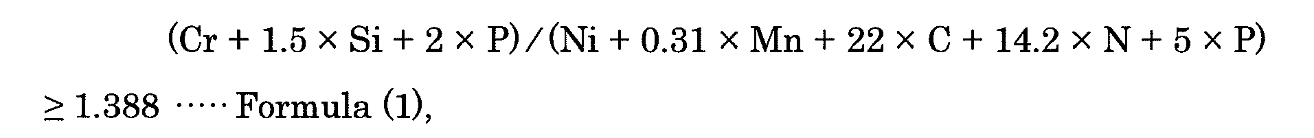
wherein each element symbol in the formula (1) represents the content by mass percent of the element concerned. - The austenitic stainless steel welding material according to claim 3, which further contains, by mass percent, at least one element selected from the first to third groups given below in lieu of part of Fe and, further, the following formula (2) is satisfied:
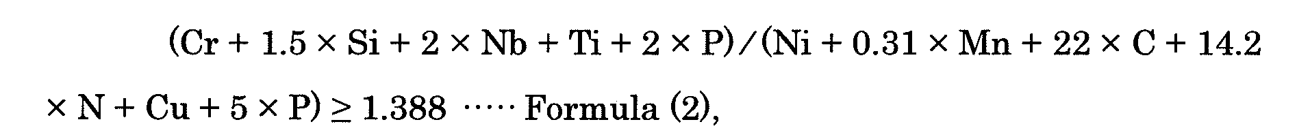
wherein each element symbol in the formula (2) represents the content by mass percent of the element concerned:First group: Nd: not more than 0.5%;Second group: one or more of Cu: not more than 3%, Mo: not more than 5% and W: not more than 10% provided that Mo + (W/2): not more than 5%, B: not more than 0.03%, V: not more than 1.5%, Nb: not more than 1.5%, Ti: not more than 2%, Ta: not more than 8%, Zr: not more than 1%, Hf: not more than 1% and Co: not more than 5%; andThird group: one or both of Ca: not more than 0.05% and Mg: not more than 0.05%.
Applications Claiming Priority (2)
| Application Number | Priority Date | Filing Date | Title |
|---|---|---|---|
| JP2006204598A JP4946242B2 (en) | 2006-07-27 | 2006-07-27 | Austenitic stainless steel welded joint and austenitic stainless steel welded material |
| PCT/JP2007/064664 WO2008013223A1 (en) | 2006-07-27 | 2007-07-26 | Austenitic stainless steel welded joint and austenitic stainless steel welding material |
Publications (3)
| Publication Number | Publication Date |
|---|---|
| EP2048255A1 true EP2048255A1 (en) | 2009-04-15 |
| EP2048255A4 EP2048255A4 (en) | 2011-04-20 |
| EP2048255B1 EP2048255B1 (en) | 2013-06-05 |
Family
ID=38981534
Family Applications (1)
| Application Number | Title | Priority Date | Filing Date |
|---|---|---|---|
| EP07791364.8A Not-in-force EP2048255B1 (en) | 2006-07-27 | 2007-07-26 | Austenitic stainless steel welded joint and austenitic stainless steel welding material |
Country Status (7)
| Country | Link |
|---|---|
| US (1) | US20090196783A1 (en) |
| EP (1) | EP2048255B1 (en) |
| JP (1) | JP4946242B2 (en) |
| KR (1) | KR20090020701A (en) |
| CN (1) | CN101495662A (en) |
| CA (1) | CA2658495C (en) |
| WO (1) | WO2008013223A1 (en) |
Cited By (5)
| Publication number | Priority date | Publication date | Assignee | Title |
|---|---|---|---|---|
| CN102159744A (en) * | 2009-06-24 | 2011-08-17 | 日立金属株式会社 | Heat-resistant steel for engine valve having excellent high-temperature strength |
| EP3178958A4 (en) * | 2015-06-05 | 2018-03-21 | Nippon Steel & Sumitomo Metal Corporation | Austenitic stainless steel |
| US10201880B2 (en) | 2011-05-13 | 2019-02-12 | Nippon Steel & Sumitomo Metal Corporation | Welding material and welding joint |
| EP3693484A4 (en) * | 2017-10-03 | 2021-01-27 | Nippon Steel Corporation | Austenitic stainless steel weld metal and welded structure |
| EP4006179A4 (en) * | 2019-07-25 | 2022-09-14 | Nippon Steel Corporation | Austenitic stainless steel material and welded joint |
Families Citing this family (39)
| Publication number | Priority date | Publication date | Assignee | Title |
|---|---|---|---|---|
| JP5218065B2 (en) | 2007-01-15 | 2013-06-26 | 新日鐵住金株式会社 | Austenitic stainless steel welded joints and austenitic stainless steel welded materials |
| EP2199419B1 (en) * | 2007-10-03 | 2018-03-07 | Nippon Steel & Sumitomo Metal Corporation | Austenitic stainless steel |
| JP4310664B1 (en) | 2008-01-25 | 2009-08-12 | 住友金属工業株式会社 | Welding materials and welded joint structures |
| JP5218200B2 (en) * | 2009-03-26 | 2013-06-26 | 新日鐵住金株式会社 | Weld metal and weld material |
| CN101664863B (en) * | 2009-09-24 | 2013-03-20 | 湖北猴王焊材有限公司 | Seawater corrosion resistant submerged arc welding wire |
| JP4835770B1 (en) * | 2010-06-07 | 2011-12-14 | 住友金属工業株式会社 | Welding material for austenitic heat resistant steel, weld metal and welded joint using the same |
| JP4835771B1 (en) * | 2010-06-14 | 2011-12-14 | 住友金属工業株式会社 | Welding material for Ni-base heat-resistant alloy, weld metal and welded joint using the same |
| JP5143960B1 (en) * | 2011-05-11 | 2013-02-13 | 株式会社神戸製鋼所 | Heat-resistant austenitic stainless steel with excellent high-temperature strength and cyclic oxidation resistance |
| AU2012279593B2 (en) * | 2011-07-06 | 2014-08-07 | Nippon Steel Corporation | Austenitic steel welded joint |
| JP5170297B1 (en) * | 2011-11-02 | 2013-03-27 | 新日鐵住金株式会社 | Welding material for Ni-base heat-resistant alloy, weld metal and welded joint using the same |
| DE102011121705A1 (en) * | 2011-12-12 | 2013-06-13 | Salzgitter Flachstahl Gmbh | Welding additive for arc and laser welding of mixed compounds of austenitic and ferritic steel |
| CN102581513B (en) * | 2012-03-06 | 2015-01-14 | 中国科学院金属研究所 | Nickel-based welding wire for main equipment of nuclear island of nuclear power station |
| CN102581512B (en) * | 2012-03-06 | 2016-04-20 | 中国科学院金属研究所 | A kind of point defect control method for nickel-based weld joint |
| CN103317256A (en) * | 2013-05-15 | 2013-09-25 | 丹阳市华龙特钢有限公司 | Austenitic stainless steel submerged-arc welding wire with excellent high-temperature strength |
| CN103836325A (en) * | 2014-03-14 | 2014-06-04 | 常熟市兰达兰基钢管附件有限公司 | Multifunctional welding steel pipe |
| JP6398277B2 (en) * | 2014-04-14 | 2018-10-03 | 新日鐵住金株式会社 | Manufacturing method of Ni-base heat-resistant alloy welded joint |
| KR101674748B1 (en) * | 2014-11-27 | 2016-11-10 | 주식회사 포스코 | Laser wellding material for stainless steel and welded metal produced thereby |
| CN104451432A (en) * | 2014-12-25 | 2015-03-25 | 春焱电子科技(苏州)有限公司 | Stainless steel alloy for electronic material |
| ES2788648T3 (en) * | 2015-06-15 | 2020-10-22 | Nippon Steel Corp | Austenitic stainless steel based on high Cr content |
| EP3317044B1 (en) * | 2015-07-01 | 2019-08-14 | Sandvik Intellectual Property AB | A method of joining a fecral alloy with a fenicr alloy using a filler metal by welding |
| CN106541222B (en) * | 2015-09-22 | 2021-03-26 | 中国科学院金属研究所 | High-temperature high-strength nuclear power nickel-based welding wire without crack defects and preparation and application thereof |
| US20190105727A1 (en) * | 2016-03-31 | 2019-04-11 | Nippon Steel & Sumitomo Metal Corporation | Welding Structure Member |
| ES2821173T3 (en) * | 2016-03-31 | 2021-04-23 | Nippon Steel Corp | Welded structural member |
| JP6638552B2 (en) * | 2016-05-09 | 2020-01-29 | 日本製鉄株式会社 | Welding material for austenitic heat-resistant steel |
| KR20190062488A (en) * | 2016-10-03 | 2019-06-05 | 닛폰세이테츠 가부시키가이샤 | Austenitic heat-resistant alloys and welding seams using them |
| CN106949318A (en) * | 2017-03-22 | 2017-07-14 | 南通盛立德金属材料科技有限公司 | A kind of Austenitic acid-resistant stainless steel pipe |
| RU2639173C1 (en) * | 2017-05-04 | 2017-12-20 | Юлия Алексеевна Щепочкина | Steel |
| CN107858589A (en) * | 2017-09-20 | 2018-03-30 | 常州凯旺金属材料有限公司 | The stainless iron and heat treatment method of a kind of corrosion-and high-temp-resistant |
| KR102031424B1 (en) * | 2017-12-01 | 2019-10-11 | 주식회사 포스코 | Austenitic stainless having excellent surface quality and mathod for manufacturing thereof |
| KR102466688B1 (en) * | 2018-02-28 | 2022-11-14 | 닛폰세이테츠 가부시키가이샤 | Austenitic stainless steel welded joints |
| JP6999479B2 (en) | 2018-04-05 | 2022-02-04 | 日鉄ステンレス株式会社 | Complete austenitic stainless steel |
| KR102094614B1 (en) * | 2018-10-30 | 2020-03-27 | 동아대학교 산학협력단 | Welding composition for hyper duplex stainless steel and method for manufacturing welding part using the same |
| CN110484836B (en) * | 2019-09-24 | 2021-01-05 | 南京佑天金属科技有限公司 | Hafnium zirconium titanium molybdenum reinforced austenitic stainless steel and preparation method thereof |
| CN110551951B (en) * | 2019-09-27 | 2020-11-13 | 常州长海焊材有限公司 | Ultralow-carbon high-temperature-resistant welding wire and preparation method thereof |
| WO2021200106A1 (en) * | 2020-03-30 | 2021-10-07 | 日鉄ステンレス株式会社 | Austenitic stainless steel |
| CN113388790B (en) * | 2021-06-08 | 2022-11-25 | 常州腾飞特材科技有限公司 | 06Cr19Ni10N austenitic stainless steel pipe and production process thereof |
| CN113549820B (en) * | 2021-06-29 | 2022-05-17 | 鞍钢股份有限公司 | High-carbon low-ferrite-content austenitic stainless steel plate and production method thereof |
| CN114505620B (en) * | 2022-04-19 | 2022-07-05 | 西安热工研究院有限公司 | Fe-Cr-Mn welding wire and preparation method and welding process thereof |
| CN114871624B (en) * | 2022-06-09 | 2023-04-18 | 上海工程技术大学 | Flux-cored wire for additive manufacturing of wagon wheels and preparation method thereof |
Citations (1)
| Publication number | Priority date | Publication date | Assignee | Title |
|---|---|---|---|---|
| EP1867743A1 (en) * | 2005-04-04 | 2007-12-19 | Sumitomo Metal Industries, Ltd. | Austenitic stainless steel |
Family Cites Families (9)
| Publication number | Priority date | Publication date | Assignee | Title |
|---|---|---|---|---|
| US2528637A (en) * | 1947-08-14 | 1950-11-07 | Armco Steel Corp | Alloy steel |
| JPS61103698A (en) * | 1984-10-26 | 1986-05-22 | Nippon Steel Corp | Austenite stainless steel welding wire which is excellent in both high temperature creep breaking strength and creep breaking elongation |
| JPS62243742A (en) * | 1986-04-17 | 1987-10-24 | Nippon Kokan Kk <Nkk> | Austenitic stainless steel having superior creep rupture strength |
| JPS62243743A (en) * | 1986-04-17 | 1987-10-24 | Nippon Kokan Kk <Nkk> | Austenitic stainless steel for use at high temperature |
| JP2664499B2 (en) | 1989-11-13 | 1997-10-15 | 新日本製鐵株式会社 | Ni-Cr austenitic stainless steel with excellent creep rupture characteristics |
| JP2636591B2 (en) * | 1991-08-30 | 1997-07-30 | 日本鋼管株式会社 | Austenitic stainless steel with excellent press formability, plastic anisotropy, and anti-cracking resistance |
| US6405214B1 (en) | 1998-12-17 | 2002-06-11 | Hewlett-Packard Company | Method of gathering usage information and transmitting to a primary server and a third party server by a client program |
| JP2001107196A (en) * | 1999-10-07 | 2001-04-17 | Sumitomo Metal Ind Ltd | Austenitic steel welded joint excellent in weld cracking resistance and sulfuric acid corrosion resistance and the welding material |
| JP4442331B2 (en) * | 2003-07-17 | 2010-03-31 | 住友金属工業株式会社 | Stainless steel and stainless steel pipe with carburization and caulking resistance |
-
2006
- 2006-07-27 JP JP2006204598A patent/JP4946242B2/en not_active Expired - Fee Related
-
2007
- 2007-07-26 KR KR1020097000814A patent/KR20090020701A/en not_active Application Discontinuation
- 2007-07-26 EP EP07791364.8A patent/EP2048255B1/en not_active Not-in-force
- 2007-07-26 CN CNA2007800279037A patent/CN101495662A/en active Pending
- 2007-07-26 WO PCT/JP2007/064664 patent/WO2008013223A1/en active Application Filing
- 2007-07-26 CA CA2658495A patent/CA2658495C/en not_active Expired - Fee Related
-
2009
- 2009-01-23 US US12/320,306 patent/US20090196783A1/en not_active Abandoned
Patent Citations (1)
| Publication number | Priority date | Publication date | Assignee | Title |
|---|---|---|---|---|
| EP1867743A1 (en) * | 2005-04-04 | 2007-12-19 | Sumitomo Metal Industries, Ltd. | Austenitic stainless steel |
Non-Patent Citations (1)
| Title |
|---|
| See also references of WO2008013223A1 * |
Cited By (7)
| Publication number | Priority date | Publication date | Assignee | Title |
|---|---|---|---|---|
| CN102159744A (en) * | 2009-06-24 | 2011-08-17 | 日立金属株式会社 | Heat-resistant steel for engine valve having excellent high-temperature strength |
| CN102159744B (en) * | 2009-06-24 | 2013-05-29 | 日立金属株式会社 | Heat-resistant steel for engine valve having excellent high-temperature strength |
| US8663549B2 (en) | 2009-06-24 | 2014-03-04 | Hitachi Metals, Ltd. | Heat-resisting steel for engine valves excellent in high-temperature strength |
| US10201880B2 (en) | 2011-05-13 | 2019-02-12 | Nippon Steel & Sumitomo Metal Corporation | Welding material and welding joint |
| EP3178958A4 (en) * | 2015-06-05 | 2018-03-21 | Nippon Steel & Sumitomo Metal Corporation | Austenitic stainless steel |
| EP3693484A4 (en) * | 2017-10-03 | 2021-01-27 | Nippon Steel Corporation | Austenitic stainless steel weld metal and welded structure |
| EP4006179A4 (en) * | 2019-07-25 | 2022-09-14 | Nippon Steel Corporation | Austenitic stainless steel material and welded joint |
Also Published As
| Publication number | Publication date |
|---|---|
| CA2658495A1 (en) | 2008-01-31 |
| EP2048255A4 (en) | 2011-04-20 |
| EP2048255B1 (en) | 2013-06-05 |
| US20090196783A1 (en) | 2009-08-06 |
| CA2658495C (en) | 2012-02-21 |
| KR20090020701A (en) | 2009-02-26 |
| JP2008030076A (en) | 2008-02-14 |
| CN101495662A (en) | 2009-07-29 |
| WO2008013223A1 (en) | 2008-01-31 |
| JP4946242B2 (en) | 2012-06-06 |
Similar Documents
| Publication | Publication Date | Title |
|---|---|---|
| EP2048255B1 (en) | Austenitic stainless steel welded joint and austenitic stainless steel welding material | |
| US8137613B2 (en) | Austenitic stainless steel welded joint and austenitic stainless steel welding material | |
| EP2199420B1 (en) | Austenitic stainless steel | |
| US10233523B2 (en) | Carburization resistant metal material | |
| EP1304394B1 (en) | Ferritic heat-resistant steel | |
| JP3446294B2 (en) | Duplex stainless steel | |
| JP6384610B2 (en) | Austenitic heat resistant alloys and welded structures | |
| CN111344427B (en) | Austenitic heat-resistant steel weld metal, weld joint, weld material for austenitic heat-resistant steel, and method for producing weld joint | |
| WO2011158706A1 (en) | WELDING MATERIAL FOR Ni-BASED HEAT-RESISTANT ALLOY, AND WELDED METAL AND WELDED JOINT EACH USING SAME | |
| US20190126408A1 (en) | Welding Structure Member | |
| US11866814B2 (en) | Austenitic stainless steel | |
| US8865060B2 (en) | Austenitic stainless steel | |
| CN111194360B (en) | Austenitic stainless steel | |
| WO2019070001A1 (en) | Austenitic stainless steel welding metal and welded structure | |
| US20190105727A1 (en) | Welding Structure Member | |
| JP6638552B2 (en) | Welding material for austenitic heat-resistant steel | |
| JP7368722B2 (en) | Austenitic heat-resistant steel weld metal, welded joints, and welding materials for austenitic heat-resistant steel |
Legal Events
| Date | Code | Title | Description |
|---|---|---|---|
| PUAI | Public reference made under article 153(3) epc to a published international application that has entered the european phase |
Free format text: ORIGINAL CODE: 0009012 |
|
| 17P | Request for examination filed |
Effective date: 20090127 |
|
| AK | Designated contracting states |
Kind code of ref document: A1 Designated state(s): AT BE BG CH CY CZ DE DK EE ES FI FR GB GR HU IE IS IT LI LT LU LV MC MT NL PL PT RO SE SI SK TR |
|
| AX | Request for extension of the european patent |
Extension state: AL BA HR MK RS |
|
| A4 | Supplementary search report drawn up and despatched |
Effective date: 20110321 |
|
| 17Q | First examination report despatched |
Effective date: 20120217 |
|
| DAX | Request for extension of the european patent (deleted) | ||
| GRAP | Despatch of communication of intention to grant a patent |
Free format text: ORIGINAL CODE: EPIDOSNIGR1 |
|
| RAP1 | Party data changed (applicant data changed or rights of an application transferred) |
Owner name: NIPPON STEEL & SUMITOMO METAL CORPORATION |
|
| GRAS | Grant fee paid |
Free format text: ORIGINAL CODE: EPIDOSNIGR3 |
|
| GRAA | (expected) grant |
Free format text: ORIGINAL CODE: 0009210 |
|
| AK | Designated contracting states |
Kind code of ref document: B1 Designated state(s): AT BE BG CH CY CZ DE DK EE ES FI FR GB GR HU IE IS IT LI LT LU LV MC MT NL PL PT RO SE SI SK TR |
|
| REG | Reference to a national code |
Ref country code: GB Ref legal event code: FG4D |
|
| REG | Reference to a national code |
Ref country code: SE Ref legal event code: TRGR |
|
| REG | Reference to a national code |
Ref country code: CH Ref legal event code: EP |
|
| REG | Reference to a national code |
Ref country code: AT Ref legal event code: REF Ref document number: 615735 Country of ref document: AT Kind code of ref document: T Effective date: 20130615 |
|
| REG | Reference to a national code |
Ref country code: IE Ref legal event code: FG4D |
|
| REG | Reference to a national code |
Ref country code: DE Ref legal event code: R096 Ref document number: 602007030912 Country of ref document: DE Effective date: 20130801 |
|
| REG | Reference to a national code |
Ref country code: AT Ref legal event code: MK05 Ref document number: 615735 Country of ref document: AT Kind code of ref document: T Effective date: 20130605 |
|
| PG25 | Lapsed in a contracting state [announced via postgrant information from national office to epo] |
Ref country code: GR Free format text: LAPSE BECAUSE OF FAILURE TO SUBMIT A TRANSLATION OF THE DESCRIPTION OR TO PAY THE FEE WITHIN THE PRESCRIBED TIME-LIMIT Effective date: 20130906 Ref country code: FI Free format text: LAPSE BECAUSE OF FAILURE TO SUBMIT A TRANSLATION OF THE DESCRIPTION OR TO PAY THE FEE WITHIN THE PRESCRIBED TIME-LIMIT Effective date: 20130605 Ref country code: LT Free format text: LAPSE BECAUSE OF FAILURE TO SUBMIT A TRANSLATION OF THE DESCRIPTION OR TO PAY THE FEE WITHIN THE PRESCRIBED TIME-LIMIT Effective date: 20130605 Ref country code: SI Free format text: LAPSE BECAUSE OF FAILURE TO SUBMIT A TRANSLATION OF THE DESCRIPTION OR TO PAY THE FEE WITHIN THE PRESCRIBED TIME-LIMIT Effective date: 20130605 Ref country code: AT Free format text: LAPSE BECAUSE OF FAILURE TO SUBMIT A TRANSLATION OF THE DESCRIPTION OR TO PAY THE FEE WITHIN THE PRESCRIBED TIME-LIMIT Effective date: 20130605 Ref country code: ES Free format text: LAPSE BECAUSE OF FAILURE TO SUBMIT A TRANSLATION OF THE DESCRIPTION OR TO PAY THE FEE WITHIN THE PRESCRIBED TIME-LIMIT Effective date: 20130916 |
|
| REG | Reference to a national code |
Ref country code: NL Ref legal event code: VDEP Effective date: 20130605 |
|
| REG | Reference to a national code |
Ref country code: LT Ref legal event code: MG4D |
|
| PG25 | Lapsed in a contracting state [announced via postgrant information from national office to epo] |
Ref country code: PL Free format text: LAPSE BECAUSE OF FAILURE TO SUBMIT A TRANSLATION OF THE DESCRIPTION OR TO PAY THE FEE WITHIN THE PRESCRIBED TIME-LIMIT Effective date: 20130605 Ref country code: BG Free format text: LAPSE BECAUSE OF FAILURE TO SUBMIT A TRANSLATION OF THE DESCRIPTION OR TO PAY THE FEE WITHIN THE PRESCRIBED TIME-LIMIT Effective date: 20130905 |
|
| PG25 | Lapsed in a contracting state [announced via postgrant information from national office to epo] |
Ref country code: LV Free format text: LAPSE BECAUSE OF FAILURE TO SUBMIT A TRANSLATION OF THE DESCRIPTION OR TO PAY THE FEE WITHIN THE PRESCRIBED TIME-LIMIT Effective date: 20130605 |
|
| PG25 | Lapsed in a contracting state [announced via postgrant information from national office to epo] |
Ref country code: IS Free format text: LAPSE BECAUSE OF FAILURE TO SUBMIT A TRANSLATION OF THE DESCRIPTION OR TO PAY THE FEE WITHIN THE PRESCRIBED TIME-LIMIT Effective date: 20131005 Ref country code: SK Free format text: LAPSE BECAUSE OF FAILURE TO SUBMIT A TRANSLATION OF THE DESCRIPTION OR TO PAY THE FEE WITHIN THE PRESCRIBED TIME-LIMIT Effective date: 20130605 Ref country code: BE Free format text: LAPSE BECAUSE OF FAILURE TO SUBMIT A TRANSLATION OF THE DESCRIPTION OR TO PAY THE FEE WITHIN THE PRESCRIBED TIME-LIMIT Effective date: 20130605 Ref country code: PT Free format text: LAPSE BECAUSE OF FAILURE TO SUBMIT A TRANSLATION OF THE DESCRIPTION OR TO PAY THE FEE WITHIN THE PRESCRIBED TIME-LIMIT Effective date: 20131007 Ref country code: EE Free format text: LAPSE BECAUSE OF FAILURE TO SUBMIT A TRANSLATION OF THE DESCRIPTION OR TO PAY THE FEE WITHIN THE PRESCRIBED TIME-LIMIT Effective date: 20130605 Ref country code: CZ Free format text: LAPSE BECAUSE OF FAILURE TO SUBMIT A TRANSLATION OF THE DESCRIPTION OR TO PAY THE FEE WITHIN THE PRESCRIBED TIME-LIMIT Effective date: 20130605 |
|
| PG25 | Lapsed in a contracting state [announced via postgrant information from national office to epo] |
Ref country code: NL Free format text: LAPSE BECAUSE OF FAILURE TO SUBMIT A TRANSLATION OF THE DESCRIPTION OR TO PAY THE FEE WITHIN THE PRESCRIBED TIME-LIMIT Effective date: 20130605 Ref country code: RO Free format text: LAPSE BECAUSE OF FAILURE TO SUBMIT A TRANSLATION OF THE DESCRIPTION OR TO PAY THE FEE WITHIN THE PRESCRIBED TIME-LIMIT Effective date: 20130605 |
|
| REG | Reference to a national code |
Ref country code: CH Ref legal event code: PL |
|
| PG25 | Lapsed in a contracting state [announced via postgrant information from national office to epo] |
Ref country code: MC Free format text: LAPSE BECAUSE OF FAILURE TO SUBMIT A TRANSLATION OF THE DESCRIPTION OR TO PAY THE FEE WITHIN THE PRESCRIBED TIME-LIMIT Effective date: 20130605 |
|
| PLBE | No opposition filed within time limit |
Free format text: ORIGINAL CODE: 0009261 |
|
| STAA | Information on the status of an ep patent application or granted ep patent |
Free format text: STATUS: NO OPPOSITION FILED WITHIN TIME LIMIT |
|
| REG | Reference to a national code |
Ref country code: IE Ref legal event code: MM4A |
|
| REG | Reference to a national code |
Ref country code: FR Ref legal event code: ST Effective date: 20140331 |
|
| PG25 | Lapsed in a contracting state [announced via postgrant information from national office to epo] |
Ref country code: DK Free format text: LAPSE BECAUSE OF FAILURE TO SUBMIT A TRANSLATION OF THE DESCRIPTION OR TO PAY THE FEE WITHIN THE PRESCRIBED TIME-LIMIT Effective date: 20130605 Ref country code: CH Free format text: LAPSE BECAUSE OF NON-PAYMENT OF DUE FEES Effective date: 20130731 Ref country code: LI Free format text: LAPSE BECAUSE OF NON-PAYMENT OF DUE FEES Effective date: 20130731 |
|
| 26N | No opposition filed |
Effective date: 20140306 |
|
| GBPC | Gb: european patent ceased through non-payment of renewal fee |
Effective date: 20130905 |
|
| PG25 | Lapsed in a contracting state [announced via postgrant information from national office to epo] |
Ref country code: IT Free format text: LAPSE BECAUSE OF FAILURE TO SUBMIT A TRANSLATION OF THE DESCRIPTION OR TO PAY THE FEE WITHIN THE PRESCRIBED TIME-LIMIT Effective date: 20130605 Ref country code: FR Free format text: LAPSE BECAUSE OF NON-PAYMENT OF DUE FEES Effective date: 20130805 |
|
| REG | Reference to a national code |
Ref country code: DE Ref legal event code: R097 Ref document number: 602007030912 Country of ref document: DE Effective date: 20140306 |
|
| PG25 | Lapsed in a contracting state [announced via postgrant information from national office to epo] |
Ref country code: GB Free format text: LAPSE BECAUSE OF NON-PAYMENT OF DUE FEES Effective date: 20130905 Ref country code: IE Free format text: LAPSE BECAUSE OF NON-PAYMENT OF DUE FEES Effective date: 20130726 |
|
| PG25 | Lapsed in a contracting state [announced via postgrant information from national office to epo] |
Ref country code: MT Free format text: LAPSE BECAUSE OF FAILURE TO SUBMIT A TRANSLATION OF THE DESCRIPTION OR TO PAY THE FEE WITHIN THE PRESCRIBED TIME-LIMIT Effective date: 20130605 Ref country code: TR Free format text: LAPSE BECAUSE OF FAILURE TO SUBMIT A TRANSLATION OF THE DESCRIPTION OR TO PAY THE FEE WITHIN THE PRESCRIBED TIME-LIMIT Effective date: 20130605 Ref country code: CY Free format text: LAPSE BECAUSE OF FAILURE TO SUBMIT A TRANSLATION OF THE DESCRIPTION OR TO PAY THE FEE WITHIN THE PRESCRIBED TIME-LIMIT Effective date: 20130605 |
|
| PG25 | Lapsed in a contracting state [announced via postgrant information from national office to epo] |
Ref country code: HU Free format text: LAPSE BECAUSE OF FAILURE TO SUBMIT A TRANSLATION OF THE DESCRIPTION OR TO PAY THE FEE WITHIN THE PRESCRIBED TIME-LIMIT; INVALID AB INITIO Effective date: 20070726 Ref country code: LU Free format text: LAPSE BECAUSE OF NON-PAYMENT OF DUE FEES Effective date: 20130726 |
|
| REG | Reference to a national code |
Ref country code: DE Ref legal event code: R082 Ref document number: 602007030912 Country of ref document: DE Representative=s name: TBK, DE Ref country code: DE Ref legal event code: R081 Ref document number: 602007030912 Country of ref document: DE Owner name: NIPPON STEEL CORPORATION, JP Free format text: FORMER OWNER: NIPPON STEEL & SUMITOMO METAL CORPORATION, TOKYO, JP |
|
| PGFP | Annual fee paid to national office [announced via postgrant information from national office to epo] |
Ref country code: SE Payment date: 20190710 Year of fee payment: 13 Ref country code: DE Payment date: 20190716 Year of fee payment: 13 |
|
| REG | Reference to a national code |
Ref country code: DE Ref legal event code: R119 Ref document number: 602007030912 Country of ref document: DE |
|
| REG | Reference to a national code |
Ref country code: SE Ref legal event code: EUG |
|
| PG25 | Lapsed in a contracting state [announced via postgrant information from national office to epo] |
Ref country code: DE Free format text: LAPSE BECAUSE OF NON-PAYMENT OF DUE FEES Effective date: 20210202 Ref country code: SE Free format text: LAPSE BECAUSE OF NON-PAYMENT OF DUE FEES Effective date: 20200727 |