EP2048030A2 - Inner mirror attachement structure - Google Patents
Inner mirror attachement structure Download PDFInfo
- Publication number
- EP2048030A2 EP2048030A2 EP08161653A EP08161653A EP2048030A2 EP 2048030 A2 EP2048030 A2 EP 2048030A2 EP 08161653 A EP08161653 A EP 08161653A EP 08161653 A EP08161653 A EP 08161653A EP 2048030 A2 EP2048030 A2 EP 2048030A2
- Authority
- EP
- European Patent Office
- Prior art keywords
- base
- guide groove
- inner mirror
- parts
- tongue
- Prior art date
- Legal status (The legal status is an assumption and is not a legal conclusion. Google has not performed a legal analysis and makes no representation as to the accuracy of the status listed.)
- Granted
Links
- 230000013011 mating Effects 0.000 claims abstract description 34
- 230000004308 accommodation Effects 0.000 claims description 15
- 229910052751 metal Inorganic materials 0.000 description 2
- 239000002184 metal Substances 0.000 description 2
- 230000000452 restraining effect Effects 0.000 description 2
- 229910052782 aluminium Inorganic materials 0.000 description 1
- XAGFODPZIPBFFR-UHFFFAOYSA-N aluminium Chemical compound [Al] XAGFODPZIPBFFR-UHFFFAOYSA-N 0.000 description 1
- 238000005452 bending Methods 0.000 description 1
- 239000000463 material Substances 0.000 description 1
- 238000000034 method Methods 0.000 description 1
- 230000000630 rising effect Effects 0.000 description 1
Images


Classifications
-
- B—PERFORMING OPERATIONS; TRANSPORTING
- B60—VEHICLES IN GENERAL
- B60R—VEHICLES, VEHICLE FITTINGS, OR VEHICLE PARTS, NOT OTHERWISE PROVIDED FOR
- B60R1/00—Optical viewing arrangements; Real-time viewing arrangements for drivers or passengers using optical image capturing systems, e.g. cameras or video systems specially adapted for use in or on vehicles
- B60R1/02—Rear-view mirror arrangements
- B60R1/04—Rear-view mirror arrangements mounted inside vehicle
Definitions
- the present invention relates to an inner mirror attachment structure for attaching an inner mirror to a front window through a base bonded to the front window
- This inner mirror attachment structure is constructed by a planar base bonded to the inner surface of a front window, and a base inner which is arranged at a base part of a stay for holding the inner mirror and clasps the base.
- the base inner is fitted to the base along the front window, and the opposing side faces of the base are clasped by the base inner, so that the base inner is mounted to the base, whereby the inner mirror is attached to the front window.
- the base used as being bonded to the front window has been commoditized so as to be compatible among various inner mirrors.
- As the commoditized base one having a small size has been employed so that the smallest inner mirror is mountable.
- the present invention provides an inner mirror attachment structure for attaching an inner mirror to a front window by fitting a base inner for holding the inner mirror to a planar base bonded to the front window; the base comprising a first base having a rear face bonded to the front window, and a second base having a recessed mating part where the first base is fitted and a wider part abutting against a side face of the first base and extending outward from the side face of the first base.
- the first and second bases are integrated, so as to construct one base, while the base inner mates with the wider part of the second base. Since the mating width of the base mating with the base inner can be expanded by the width of the wider part of the second base as such, the force by which the base holds the inner mirror can be improved even when the first base is commoditized. If the mating structure between the base inner and the base is altered, only the second base will be required to change its form, while leaving the first base commoditized. This can increase the degree of freedom in designing the mating structure between the base inner and the base.
- the first base has a first flange part projecting along a front face from the side face, while a wall forming the mating part in the second base is formed with a first groove part where the first flange part is fitted.
- the front face of the first base is formed with a first guide groove extending inward from an end part
- the second base has a tongue fitted into the first guide groove, and the tongue projects toward the mating part.
- the tongue of the second base is fitted into the first guide groove of the first base in this inner mirror attachment structure
- the second base is restrained from moving toward the front window, since the tongue abuts against the groove bottom forming the first guide groove.
- the second base thus holds the first base between the tongue and the wall face forming the first groove part, thereby making it possible to keep the second base from jolting against the first base and improve the fastening force between the first and second bases.
- the first base has a second flange part projecting along the front face from a wall face forming the first guide groove, while a side face of the tongue of the second base is formed with a second groove part where the second flange part is fitted.
- the second flange part of the first base is fitted into the second groove part of the tongue of the second base in this inner mirror attachment structure, the second base is restrained from moving toward the front window, since the wall face forming the second groove part abuts against the second flange part.
- the second base holds the first base with the tongue not only by the wall face forming the first groove part but also by the wall face forming the second groove part, thereby making it possible to further keep the second base from jolting against the first base and further improve the fastening force between the first and second bases.
- the base inner has a protrusion projecting toward a base accommodation space where the base is inserted and accommodated, while a front face of the tongue of the second base is formed with a second guide groove extending along the first guide groove from an end part, such that the protrusion is introduced into the second guide groove when the base is inserted into the base accommodation space.
- the guide groove guides the protrusion, whereby the base inner is allowed to advance along the first guide groove. This can smoothly mate the base inner with the second base, thereby improving the workability.
- the present invention can improve the force by which the base holds the inner mirror.
- an inner mirror attachment structure 1 is one by which an inner mirror 2 is attached to a front window 3 through a base 4 bonded to the front window 3.
- a mirror 2a for the driver to observe the rear is attached to the front face side of the inner mirror 2.
- a stay 5 for holding the inner mirror 2 is attached to the back face side of the inner mirror 2.
- the stay 5 projects from the front window 3 to the interior and has a base part to which a base inner 6 for clasping the base 4 is attached.
- Both ends of the stay 5 are provided with spherical heads 5a, 5b, respectively.
- the spherical head 5a and the inner mirror 2 are ball-jointed, so that the inner mirror 2 is tiltably held by the stay 5.
- the spherical head 5b and the base inner 6 are ball-jointed, so that the stay 5 is tiltably held by the base inner 6.
- the spherical head 5b is provided with a protrusion 7 which projects to the base inner 6.
- the protrusion 7 abuts against the base 4, thereby restraining the stay 5 from tilting further.
- the base inner 6 holds the inner mirror 2 through the stay 5 and is held by the base 4.
- the base inner 6 is provided with a stay holding part 11 and a base clasping part 13.
- the stay holding part 11 is provided with a spherically recessed surface 10 corresponding to the form of the spherical head 5b of the stay 5, while the base clasping part 13 is formed with a base accommodation space 12 for accommodating the base 4.
- the base clasping part 13 is integrated with the stay holding part 11 and substantially formed like a box.
- the base clasping part 13 is formed with a rear opening 14 which is open to the front window 3, and a lower opening 15 which is open downward.
- the base clasping part 13 is provided with a pair of opposing side walls 16a, 16b which extend from the stay holding part 11 to the lower opening 15 and form sidewall of the base inner 6.
- the base clasping part 13 is also provided with an upper end wall 18 which connects the side walls 16a, 16b to each other at a position opposing the lower opening 15.
- the upper end parts of the side walls 16a, 16b are provided with clasping parts 20a, 20b which project toward each other and extend along the side walls 16a, 16b, respectively, while the base 4 accommodated in the base accommodation space 12 is clasped by the clasping parts 20a, 20b.
- the inner end faces 21a, 21b of the clasping parts 20a, 20b are formed as tilted surfaces which reduce the distance therebetween as they approach the front window 3.
- the inner end faces 21 a, 21b of the clasping parts 20a, 20b are provided with spring recesses 22a, 22b which extend along the clasping parts 20a, 20b, respectively.
- a spring 13 for elastically holding the base 4 is fitted into the spring recesses 22a, 22b.
- a cylindrical part 24 projects from the stay holding part 11 to the base accommodation space 12.
- the upper end of the cylindrical part 24 is provided with a planar base support plate 25 which supports the base 4.
- the base accommodation space 12 is formed by the base support plate 25, the side walls 16a, 16b, and the upper end wall 18.
- the base support plate 25 is arranged such as to be separated from the side walls 16a, 16b and the upper end wall 18, and has a rectangular form.
- the protrusion 7 of the stay 5 is inserted into a through hole 26 provided in the base support plate 25 and cylindrical part 24.
- a cutout 27 is formed in the base support plate 25 between the end part 25a on the lower opening 15 side and the through hole 26, whereby the base support plate 25 is easier to flex.
- a protrusion 28 projecting to the base accommodation space 12 is provided in the base support plate 25 between the cutout 27 and the end part 25a.
- the base 4 accommodated in the base accommodation space 12 is supported by the protrusion 28 from the lower opening 15 side.
- the spring 19 fitted into the spring recesses 22a, 22b is formed by bending a wire rod.
- the spring 19 is constituted by a U-shaped part 19a abutting against the periphery of the cylindrical part 24 and extending to the vicinity of the upper end wall 18, a pair of base abutting parts 19d, 19e fitted into the spring recesses 22a, 22b of the clasping parts 20a, 20b, and a pair of connecting parts 19b, 19c which connect the U-shaped part 19a to the base abutting parts 19d, 19e, respectively.
- the spring 19 is inserted into the base inner 6 from the lower opening 15, so that the U-shaped part 19a abuts against the cylindrical part 24, while the base abutting parts 19d, 19e are fitted into spring recesses 22a, 22b, respectively, whereby the spring 19 is mounted to the base inner 6.
- the base 4 which is formed from aluminum, is constituted by a first base 30 bonded to the front window 3 and a second base 40 clasped by the base inner 6.
- the first base 30 is formed like a substantially trapezoidal plate with chamfered corners.
- the first base 30 has a rear face 31 to be bonded to the front window 3, a front face 32 opposing the rear face 31 and facing the interior, a pair of opposing side faces 33a, 33b which determine the width of the first base 30, a lower end face 35 which is faced down and positioned on the front side in a mating direction S along which the base inner 6 mates with the base 4, and an upper end face 36 which is faced up and positioned on the rear side in the mating direction S.
- the first base 30 is bonded to the front window 3 with the upper end face 36 facing up.
- the side faces 33a, 33b of the first base 30 are tilted such as to extend outward from the rear face 31 to the front face 32.
- the side faces 33a, 33b are provided with flange parts 37a, 37b (a first flange part) projecting along the front face 32 from the side faces 33a, 33b.
- the front face 32 of the first base 30 is formed with a guide groove 39 (a first guide groove) extending along the mating direction S from the end part 32a on the upper end face 36 side to the inside (the center of the front face 32).
- the guide groove 39 is arranged at the center in the width direction of the first base 30, while the groove bottom is formed as a tilted surface which becomes shallower toward the inner side.
- the second base 40 is formed like an inverted U.
- the second base 40 is formed slightly thinner than the first base 30, while having a rear face 45 facing the front window 3 and a front face 46 facing the interior which are planes parallel to each other.
- the second base 40 is provided with a pair of opposing wider parts 41 a, 41b (a wall forming a mating part) which extend like arms, and a connecting part 42 which connects the wider parts 41 a, 41b to each other in the upper part.
- a mating part 43 for inserting the first base 30 is formed in an area delimited by the wider parts 41 a, 41b and the connecting part 42.
- the wider parts 41a, 41b are formed symmetrical to each other about the center axis extending in the mating direction S.
- the wider parts 41a, 41b abut against and extend outward from the side faces 33a, 33b of the first base 30 inserted into the mating part 43, respectively.
- the first base 30 and the second base 40 are integrated with each other, so as to form the single base 4 as shown in Figs. 6 and 7 .
- the base inner 6 clasps the wider parts 41a, 41b through the base abutting parts 19d, 19e of the spring 19, so as to be held by the base 4.
- the clasping width of the base 4 clasped by the base inner 6 can be expanded by the widths of the wider parts 41a, 41b of the second base 40, whereby the force by which the base 4 holds the inner mirror 2 can be improved even when the first base 30 is commoditized.
- Such an improvement in the holding force can suppress chatter vibrations and the like between the base and the base inner without providing dampers and the like against chatter vibrations.
- the inner side faces 44a, 44b of the wider parts 41a, 41b abut against the side faces 33a, 33b of the first base 30 and are tilted such as to extend outward from the rear faces 45a, 45b to the front faces 46a, 46b.
- L-shaped groove parts 47a, 47b (a first groove part) extending along the wider parts 41a, 41b are formed in boundary parts between the inner side faces 44a, 44b and the front faces 46a, 46b, respectively.
- the flange parts 37a, 37b thus fitted into the groove parts 47a, 47b abut against the wall faces forming the groove parts 47a, 47b, so as to be restrained from moving away from the front window 3. This can reliably prevent the second base 40 from dropping out of the first base 30.
- the groove parts 47a, 47b are formed by the same width as that of the flange parts 37a, 37b. Therefore, when the flanges 37a, 37b are fitted into the groove parts 47a, 47b, the front face 32 of the first base 30 becomes flush with the front faces 46a, 46b of the second base 40, whereby the front face 4a of the base 4 can be formed as a plane without steps. This can bring the front face of the base support plate 25 of the base inner 6 into close contact with the front faces of the first base 30 and second base 40 (see Fig. 3 ).
- the outer side faces 48a, 48b of the wider parts 41a, 41b are tilted such as to extend outward from the rear faces 45a, 45b to the front faces 46a, 46b.
- the end parts of the outer side faces 48a, 48b on the side of the front faces 46a, 46b are provided with flange parts 49a, 49b projecting along the front faces 46a, 46b, respectively.
- the connecting part 42 of the second base 40 is provided with a tongue 50 fitted into the guide groove 39 of the first base 30.
- the tongue 50 projects toward center of the mating part 43 from the connecting part 42 and has the same shape as that of the guide groove 39 of the first base 30 in order to fit completely into the guide groove 39.
- the rear face of the tongue 50 is formed with a tilted surface 51 having the same gradient as that of the groove bottom of the guide groove 39 in the first base 30, while the front face 52 is formed flush with the front face 46 of the second base 40 (the front faces 46a, 46b of the wider parts 41 a, 41 b).
- the tongue 50 When the tongue 50 is fitted into the guide groove 39 of the first base 30, the tongue 50 abuts against the groove bottom forming the guide groove 39, thereby restraining the second base 40 from moving toward the front window 3. This can keep the gap between the second base 40 and the front window 3, so as to prevent the second base 40 from coming into contact with the front window 3. Since the front face 4a of the base 4 becomes flat, the base support plate 25 of base inner 6 can uniformly support the first base 30 and second base 40.
- the second base 40 is restrained from jolting against the first base 30, and the fastening force between the first base 30 and second base 40 can be improved. Since both of the guide groove 39 and the outer face of the tongue 50 are formed with tilted surfaces, the adhesion between the first base 30 and second base 40 can be improved.
- the front face 52 of the tongue 50 is formed with a guide groove 54 (a second guide groove) for guiding the protrusion 28 (see Fig. 1 ) provided in the base support plate 25.
- the guide groove 54 is arranged at the center in the width direction of the tongue 50, and extends along the mating direction S from the end part 40a of the second base 40 to the leading end part 53 of the tongue 50.
- the groove bottom of the guide groove 54 is formed as a tilted surface which becomes shallower toward the leading end part 53 of the tongue 50.
- the first base 30 is inserted into the mating part 43 of the second base 40, so that the second base 40 mates with the first base 30 in the mating direction S.
- the inner side faces 44a, 44b of the second base 40 abut against the side faces 33a, 33b of the first base 30, and the flange parts 37a, 37b of the first base 30 fit into the groove parts 47a, 47b of the second base 40.
- the tongue 50 of the second base 40 is inserted into the guide groove 39 of the first base 30.
- the second base 40 is integrally connected to the first base 30 by holding the first base 30 with the tongue 50 and the walls forming the groove parts 47a, 47b. In this state, the rear face 31 is bonded to the front window 3.
- the base inner 6 having the inner mirror 2 attached thereto is mated with the base 4 in which the first base 30 and second base 40 are integrally connected to each other, so as to insert the base 4 into the base accommodation space 12 in the base inner 6 as shown in Figs. 8 and 9 .
- the protrusion 28 of the base support plate 25 is introduced into the guide groove 54 of the second base 40, so as to be guided in the mating direction S.
- the protrusion 28 is pushed by the groove bottom of the guide groove 54, whereby the base support plate 25 flexes.
- the protrusion 28 is pushed back by a restoring force of the base support plate 25, whereby the lower end face 35 of the first base 30 is supported by the protrusion 28.
- the base inner 6 can be guided in the mating direction S by providing the guide groove 54 in which the protrusion 28 is introduced when inserting the base 4 into the base accommodation space 12.
- the clasping parts 20a, 20b of the base inner 6 abut against the outer side faces 48a, 48b and flange parts 49a, 49b of the second base 40 through the base abutting parts 19d, 19e of the spring 19 as shown in Fig. 3 .
- the base support plate 25 of the base inner 6 abuts against the front face 32 of the first base 30 and the front face 46 of the second base 40.
- the base inner 6 is thus integrally connected to the base 4 by holding the base 4 with the clasping parts 20a, 20b and the base support plate 25 and clasping the outer side faces 48a, 48b of the second base 40.
- the inner mirror 2 is held by the base 4, so that the inner mirror 2 is attached to the front window 3.
- a base 60 in another example has a second base 61 formed by such a thickness as to project from the front face of the first base 30.
- groove parts 62a, 62b are provided in the inner side faces 64a, 64b.
- the flange parts 37a, 37b fitted into the groove parts 62a, 62b are held between a pair of opposing walls forming the groove parts 62a, 62b of the second base 61.
- the groove parts 62a, 62b in the inner side faces 64a, 64b allows the pair of opposing walls forming the groove parts 62a, 62b to hold the flange parts 37a, 37b therebetween. This can further improve the fastening force between the first base 30 and second base 61.
- a base 70 in still another example has a first base 71 provided with flange parts 74a, 74b (a second flange part) projecting along front faces 71a, 71b from wall faces 73a, 73b forming a guide groove 72 (a first guide groove).
- a tongue 76 of a second base 75 is provided with groove parts 79a, 79b (a second groove part) formed along a front face 78 from side faces 77a, 77b.
- the tongue 76 is held with the groove bottom of the guide groove 72 and the flange parts 74a, 74b.
- the tongue 76 is provided with the groove parts 79a, 79b, and the wall faces 73a, 73b forming the guide groove 72 are provided with the flange parts 74a, 74b, whereby the tongue 76 can be held with the groove bottom of the guide groove 72 and the flange parts 74a, 74b. This can further improve the fastening force between the first base 71 and second base 75.
- the base 80 in another example has a second base 8 in which a tongue 82 is formed by such a thickness as to project from the front faces 71 a, 71 b of the first base 71.
- groove parts 83a, 83b (a second groove part) are provided in side faces 84a, 84b of the tongue 82.
- the flange parts 74a, 74b are held by a pair of opposing walls forming the groove parts 83a, 83b of the tongue 82.
- the groove parts 83a, 83b formed in the tongue 82 are provided in the side faces 84a, 84b, whereby the pair of opposing walls forming the groove parts 83a, 83b can hold the flange parts 74a, 74b. This can further improve the fastening force between the first base 71 and second base 81.
- the present invention is not limited to the above-mentioned embodiment.
- the above-mentioned embodiment relates to a clasping structure in which the base inner 6 mates with the base 4 in the mating direction S
- any structure can be used as the clasping structure between the base and the base inner.
- the clasping structure may be one which can detachably mount the base inner to the base in a direction orthogonal to the front window. Even if the clasping structure between the base inner and the base is altered, only the wider part of the second base will be required to change its form, while leaving the first base commoditized, whereby the degree of freedom in designing the clasping structure between the base inner and the base can be increased.
- the first base and second base may be formed from materials different from each other. For example, forming the first base to be commoditized and the second base from an inexpensive metal and an expensive metal having a high strength, respectively, can improve the strength of the base, while keeping the cost from rising.
- the second base may incorporate a power supply or electrode therein. This makes it possible to feed power to the inner mirror even after bonding the first base to the front window, whereby the range of utilization of the inner mirror can be expanded greatly.
Landscapes
- Engineering & Computer Science (AREA)
- Multimedia (AREA)
- Mechanical Engineering (AREA)
- Rear-View Mirror Devices That Are Mounted On The Exterior Of The Vehicle (AREA)
- Mounting And Adjusting Of Optical Elements (AREA)
- Telescopes (AREA)
Abstract
Description
- The present invention relates to an inner mirror attachment structure for attaching an inner mirror to a front window through a base bonded to the front window
- Conventionally known as a technique in such a field is an inner mirror attachment structure disclosed in
Patent Document 1. This inner mirror attachment structure is constructed by a planar base bonded to the inner surface of a front window, and a base inner which is arranged at a base part of a stay for holding the inner mirror and clasps the base. The base inner is fitted to the base along the front window, and the opposing side faces of the base are clasped by the base inner, so that the base inner is mounted to the base, whereby the inner mirror is attached to the front window. - The base used as being bonded to the front window has been commoditized so as to be compatible among various inner mirrors. As the commoditized base, one having a small size has been employed so that the smallest inner mirror is mountable.
[Patent Document 1] Published International Patent ApplicationWO 03/041999 - As vehicles have recently been diversifying their functions, inner mirrors have been mounted with accessories such as cameras, thereby increasing their weight. Since the bases have been commoditized, however, there have been cases where the base clasping width of the base inner becomes narrower per weight of the inner mirror in the conventional inner mirror attachment structure, thereby making it harder for the base to fully support the inner mirror. Because of such a decrease in the holding force, chatter vibrations and the like have occurred between the base and the base inner when the vehicle body vibrates.
- It is an object of the present invention to provide an inner mirror attachment structure which can improve the force by which the base holds the inner mirror.
- The present invention provides an inner mirror attachment structure for attaching an inner mirror to a front window by fitting a base inner for holding the inner mirror to a planar base bonded to the front window; the base comprising a first base having a rear face bonded to the front window, and a second base having a recessed mating part where the first base is fitted and a wider part abutting against a side face of the first base and extending outward from the side face of the first base.
- When the first base mates with the mating part of the second base in this inner mirror attachment structure, the first and second bases are integrated, so as to construct one base, while the base inner mates with the wider part of the second base. Since the mating width of the base mating with the base inner can be expanded by the width of the wider part of the second base as such, the force by which the base holds the inner mirror can be improved even when the first base is commoditized. If the mating structure between the base inner and the base is altered, only the second base will be required to change its form, while leaving the first base commoditized. This can increase the degree of freedom in designing the mating structure between the base inner and the base.
- It will be preferred in this case if the first base has a first flange part projecting along a front face from the side face, while a wall forming the mating part in the second base is formed with a first groove part where the first flange part is fitted. When the first flange part of the first base is fitted into the first groove part of the second base in this inner mirror attachment structure, the second base is restrained from moving away from the front window, since the wall face forming the first groove part abuts against the first flange part. This can reliably prevent the second base from dropping out of the first base.
- Preferably, the front face of the first base is formed with a first guide groove extending inward from an end part, the second base has a tongue fitted into the first guide groove, and the tongue projects toward the mating part. When the tongue of the second base is fitted into the first guide groove of the first base in this inner mirror attachment structure, the second base is restrained from moving toward the front window, since the tongue abuts against the groove bottom forming the first guide groove. The second base thus holds the first base between the tongue and the wall face forming the first groove part, thereby making it possible to keep the second base from jolting against the first base and improve the fastening force between the first and second bases.
- Preferably, the first base has a second flange part projecting along the front face from a wall face forming the first guide groove, while a side face of the tongue of the second base is formed with a second groove part where the second flange part is fitted. When the second flange part of the first base is fitted into the second groove part of the tongue of the second base in this inner mirror attachment structure, the second base is restrained from moving toward the front window, since the wall face forming the second groove part abuts against the second flange part. Thus, the second base holds the first base with the tongue not only by the wall face forming the first groove part but also by the wall face forming the second groove part, thereby making it possible to further keep the second base from jolting against the first base and further improve the fastening force between the first and second bases.
- Preferably, the base inner has a protrusion projecting toward a base accommodation space where the base is inserted and accommodated, while a front face of the tongue of the second base is formed with a second guide groove extending along the first guide groove from an end part, such that the protrusion is introduced into the second guide groove when the base is inserted into the base accommodation space. When the protrusion is introduced into the second guide groove at the time of inserting the base into the base accommodation space in this inner mirror attachment structure, the guide groove guides the protrusion, whereby the base inner is allowed to advance along the first guide groove. This can smoothly mate the base inner with the second base, thereby improving the workability.
- The present invention can improve the force by which the base holds the inner mirror.
-
- [
Fig. 1 ] is an exploded perspective view showing an embodiment of the inner mirror attachment structure in accordance with the present invention; - [
Fig. 2 ] is a side view of the inner mirror attachment structure shown inFig. 1 ; - [
Fig. 3 ] is a sectional view taken along the line III-III ofFig. 2 ; - [
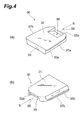
Fig. 4 ] (a) and (b) are perspective views of the first base as seen from the front and rear face sides, respectively; - [
Fig. 5 ] (a) and (b) are perspective views of the second base as seen from the front and rear face sides, respectively; - [
Fig. 6 ] is a perspective view showing a state where the first base is fitted into the second base; - [
Fig. 7 ] is a sectional view taken along the line VII-VII ofFig. 6 ; - [
Fig. 8 ] is a perspective view showing a state before mounting the inner mirror to the base; - [
Fig. 9 ] is a perspective view showing a state after mounting the inner mirror to the base; - [
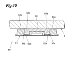
Fig. 10 ] is a sectional view showing another example of the base; - [
Fig. 11 ] is a sectional view showing still another example of the base; and - [
Fig. 12 ] is a sectional view showing still another example of the base. - In the following, preferred embodiments of the inner mirror attachment structure in accordance with the present invention will be explained with reference to the drawings.
- As shown in
Figs. 1 to 3 , an innermirror attachment structure 1 is one by which aninner mirror 2 is attached to afront window 3 through abase 4 bonded to thefront window 3. - A
mirror 2a for the driver to observe the rear is attached to the front face side of theinner mirror 2. Astay 5 for holding theinner mirror 2 is attached to the back face side of theinner mirror 2. The stay 5 projects from thefront window 3 to the interior and has a base part to which a base inner 6 for clasping thebase 4 is attached. Both ends of thestay 5 are provided withspherical heads spherical head 5a and theinner mirror 2 are ball-jointed, so that theinner mirror 2 is tiltably held by thestay 5. Similarly, thespherical head 5b and the base inner 6 are ball-jointed, so that thestay 5 is tiltably held by the base inner 6. Thespherical head 5b is provided with aprotrusion 7 which projects to the base inner 6. When the stay 5 tilts beyond its typical usage range, theprotrusion 7 abuts against thebase 4, thereby restraining thestay 5 from tilting further. - The base inner 6 holds the
inner mirror 2 through thestay 5 and is held by thebase 4. The base inner 6 is provided with astay holding part 11 and abase clasping part 13. Thestay holding part 11 is provided with a sphericallyrecessed surface 10 corresponding to the form of thespherical head 5b of thestay 5, while thebase clasping part 13 is formed with abase accommodation space 12 for accommodating thebase 4. - The
base clasping part 13 is integrated with thestay holding part 11 and substantially formed like a box. Thebase clasping part 13 is formed with arear opening 14 which is open to thefront window 3, and alower opening 15 which is open downward. Thebase clasping part 13 is provided with a pair ofopposing side walls stay holding part 11 to thelower opening 15 and form sidewall of the base inner 6. Thebase clasping part 13 is also provided with anupper end wall 18 which connects theside walls lower opening 15. - The upper end parts of the
side walls parts side walls base 4 accommodated in thebase accommodation space 12 is clasped by the claspingparts clasping parts front window 3. The inner end faces 21 a, 21b of theclasping parts spring recesses clasping parts spring 13 for elastically holding thebase 4 is fitted into the spring recesses 22a, 22b. - In the space delimited by the
side walls upper end wall 18 within the base inner 6, on the other hand, acylindrical part 24 projects from thestay holding part 11 to thebase accommodation space 12. The upper end of thecylindrical part 24 is provided with a planarbase support plate 25 which supports thebase 4. Thebase accommodation space 12 is formed by thebase support plate 25, theside walls upper end wall 18. - The
base support plate 25 is arranged such as to be separated from theside walls upper end wall 18, and has a rectangular form. Theprotrusion 7 of thestay 5 is inserted into a throughhole 26 provided in thebase support plate 25 andcylindrical part 24. Acutout 27 is formed in thebase support plate 25 between theend part 25a on thelower opening 15 side and the throughhole 26, whereby thebase support plate 25 is easier to flex. Aprotrusion 28 projecting to thebase accommodation space 12 is provided in thebase support plate 25 between thecutout 27 and theend part 25a. Thebase 4 accommodated in thebase accommodation space 12 is supported by theprotrusion 28 from thelower opening 15 side. - On the other hand, the
spring 19 fitted into the spring recesses 22a, 22b is formed by bending a wire rod. Thespring 19 is constituted by aU-shaped part 19a abutting against the periphery of thecylindrical part 24 and extending to the vicinity of theupper end wall 18, a pair ofbase abutting parts clasping parts parts U-shaped part 19a to thebase abutting parts spring 19 is inserted into the base inner 6 from thelower opening 15, so that theU-shaped part 19a abuts against thecylindrical part 24, while thebase abutting parts spring recesses spring 19 is mounted to thebase inner 6. - The
base 4, which is formed from aluminum, is constituted by afirst base 30 bonded to thefront window 3 and asecond base 40 clasped by thebase inner 6. - As shown in
Fig. 4 , thefirst base 30 is formed like a substantially trapezoidal plate with chamfered corners. Thefirst base 30 has arear face 31 to be bonded to thefront window 3, afront face 32 opposing therear face 31 and facing the interior, a pair of opposing side faces 33a, 33b which determine the width of thefirst base 30, alower end face 35 which is faced down and positioned on the front side in a mating direction S along which the base inner 6 mates with thebase 4, and an upper end face 36 which is faced up and positioned on the rear side in the mating direction S. Thefirst base 30 is bonded to thefront window 3 with the upper end face 36 facing up. - The side faces 33a, 33b of the
first base 30 are tilted such as to extend outward from therear face 31 to thefront face 32. The side faces 33a, 33b are provided withflange parts front face 32 from the side faces 33a, 33b. Thefront face 32 of thefirst base 30 is formed with a guide groove 39 (a first guide groove) extending along the mating direction S from theend part 32a on the upper end face 36 side to the inside (the center of the front face 32). Theguide groove 39 is arranged at the center in the width direction of thefirst base 30, while the groove bottom is formed as a tilted surface which becomes shallower toward the inner side. - As shown in
Fig. 5 , thesecond base 40 is formed like an inverted U. Thesecond base 40 is formed slightly thinner than thefirst base 30, while having arear face 45 facing thefront window 3 and afront face 46 facing the interior which are planes parallel to each other. Thesecond base 40 is provided with a pair of opposingwider parts part 42 which connects thewider parts mating part 43 for inserting thefirst base 30 is formed in an area delimited by thewider parts part 42. - The
wider parts wider parts first base 30 inserted into themating part 43, respectively. - When the
first base 30 is inserted into themating part 43 in thesecond base 40, thefirst base 30 and thesecond base 40 are integrated with each other, so as to form thesingle base 4 as shown inFigs. 6 and7 . The base inner 6 clasps thewider parts base abutting parts spring 19, so as to be held by thebase 4. When thesecond base 40 equipped with thewider parts first base 30 as such, the clasping width of thebase 4 clasped by the base inner 6 can be expanded by the widths of thewider parts second base 40, whereby the force by which thebase 4 holds theinner mirror 2 can be improved even when thefirst base 30 is commoditized. Such an improvement in the holding force can suppress chatter vibrations and the like between the base and the base inner without providing dampers and the like against chatter vibrations. - As shown in
Fig. 5 , the inner side faces 44a, 44b of thewider parts first base 30 and are tilted such as to extend outward from the rear faces 45a, 45b to the front faces 46a, 46b. L-shapedgroove parts wider parts first base 30 is inserted into themating part 43 of thesecond base 40, theflange parts first base 30 are fitted into thegroove parts flange parts groove parts groove parts front window 3. This can reliably prevent thesecond base 40 from dropping out of thefirst base 30. - The
groove parts flange parts flanges groove parts front face 32 of thefirst base 30 becomes flush with the front faces 46a, 46b of thesecond base 40, whereby thefront face 4a of thebase 4 can be formed as a plane without steps. This can bring the front face of thebase support plate 25 of the base inner 6 into close contact with the front faces of thefirst base 30 and second base 40 (seeFig. 3 ). - As with the inner side faces 44a, 44b, the outer side faces 48a, 48b of the
wider parts flange parts - The connecting
part 42 of thesecond base 40 is provided with atongue 50 fitted into theguide groove 39 of thefirst base 30. Thetongue 50 projects toward center of themating part 43 from the connectingpart 42 and has the same shape as that of theguide groove 39 of thefirst base 30 in order to fit completely into theguide groove 39. The rear face of thetongue 50 is formed with a tiltedsurface 51 having the same gradient as that of the groove bottom of theguide groove 39 in thefirst base 30, while thefront face 52 is formed flush with thefront face 46 of the second base 40 (the front faces 46a, 46b of thewider parts tongue 50 is fitted into theguide groove 39 of thefirst base 30, thetongue 50 abuts against the groove bottom forming theguide groove 39, thereby restraining thesecond base 40 from moving toward thefront window 3. This can keep the gap between thesecond base 40 and thefront window 3, so as to prevent thesecond base 40 from coming into contact with thefront window 3. Since thefront face 4a of thebase 4 becomes flat, thebase support plate 25 of base inner 6 can uniformly support thefirst base 30 andsecond base 40. - Since the
tongue 50 fits into theguide groove 39 as shown inFig. 7 , thesecond base 40 is restrained from jolting against thefirst base 30, and the fastening force between thefirst base 30 andsecond base 40 can be improved. Since both of theguide groove 39 and the outer face of thetongue 50 are formed with tilted surfaces, the adhesion between thefirst base 30 andsecond base 40 can be improved. - The
front face 52 of thetongue 50 is formed with a guide groove 54 (a second guide groove) for guiding the protrusion 28 (seeFig. 1 ) provided in thebase support plate 25. Theguide groove 54 is arranged at the center in the width direction of thetongue 50, and extends along the mating direction S from theend part 40a of thesecond base 40 to theleading end part 53 of thetongue 50. The groove bottom of theguide groove 54 is formed as a tilted surface which becomes shallower toward theleading end part 53 of thetongue 50. When theprotrusion 28 is introduced into theguide groove 54, theguide groove 54 guides theprotrusion 28, so as to advance the base inner 6 along theguide groove 54. This allows the base inner 6 to smoothly mate with thesecond base 40, and thus can improve the workability. - Operations for attaching the
inner mirror 2 to thefront window 3 will now be explained. - First, as shown in
Fig. 6 , thefirst base 30 is inserted into themating part 43 of thesecond base 40, so that thesecond base 40 mates with thefirst base 30 in the mating direction S. - In this case, as shown in
Fig. 7 , the inner side faces 44a, 44b of thesecond base 40 abut against the side faces 33a, 33b of thefirst base 30, and theflange parts first base 30 fit into thegroove parts second base 40. Thetongue 50 of thesecond base 40 is inserted into theguide groove 39 of thefirst base 30. Thesecond base 40 is integrally connected to thefirst base 30 by holding thefirst base 30 with thetongue 50 and the walls forming thegroove parts rear face 31 is bonded to thefront window 3. - Thereafter, along the mating direction S, the base inner 6 having the
inner mirror 2 attached thereto is mated with thebase 4 in which thefirst base 30 andsecond base 40 are integrally connected to each other, so as to insert thebase 4 into thebase accommodation space 12 in the base inner 6 as shown inFigs. 8 and9 . - Here, the
protrusion 28 of thebase support plate 25 is introduced into theguide groove 54 of thesecond base 40, so as to be guided in the mating direction S. As the base inner 6 advances in the mating direction S, theprotrusion 28 is pushed by the groove bottom of theguide groove 54, whereby thebase support plate 25 flexes. After thebase 4 passes theprotrusion 28, theprotrusion 28 is pushed back by a restoring force of thebase support plate 25, whereby thelower end face 35 of thefirst base 30 is supported by theprotrusion 28. Thus providing theprotrusion 28 can prevent thebase 4 accommodated in thebase accommodation space 12 from dropping out. The base inner 6 can be guided in the mating direction S by providing theguide groove 54 in which theprotrusion 28 is introduced when inserting thebase 4 into thebase accommodation space 12. - When the
base 4 is inserted into thebase accommodation space 12 of the base inner 6, theclasping parts flange parts second base 40 through thebase abutting parts spring 19 as shown inFig. 3 . On the other hand, thebase support plate 25 of the base inner 6 abuts against thefront face 32 of thefirst base 30 and thefront face 46 of thesecond base 40. The base inner 6 is thus integrally connected to thebase 4 by holding thebase 4 with theclasping parts base support plate 25 and clasping the outer side faces 48a, 48b of thesecond base 40. As a consequence, theinner mirror 2 is held by thebase 4, so that theinner mirror 2 is attached to thefront window 3. - As shown in
Fig. 10 , a base 60 in another example has asecond base 61 formed by such a thickness as to project from the front face of thefirst base 30. Inwider parts second base 61,groove parts first base 30 is inserted into thesecond base 61 in thus constructedbase 60, theflange parts first base 30 fit into thegroove parts second base 61. Theflange parts groove parts groove parts second base 61. Thus providing thegroove parts groove parts flange parts first base 30 andsecond base 61. - As shown in
Fig. 11 , a base 70 in still another example has afirst base 71 provided withflange parts tongue 76 of asecond base 75 is provided withgroove parts first base 71 is inserted into thesecond base 75 in thus constructedbase 70, theflange parts first base 71 fit into thegroove parts tongue 76 in thesecond base 75. Thetongue 76 is held with the groove bottom of theguide groove 72 and theflange parts tongue 76 is provided with thegroove parts guide groove 72 are provided with theflange parts tongue 76 can be held with the groove bottom of theguide groove 72 and theflange parts first base 71 andsecond base 75. - As shown in
Fig. 12 , the base 80 in another example has a second base 8 in which atongue 82 is formed by such a thickness as to project from the front faces 71 a, 71 b of thefirst base 71. In thesecond base 81,groove parts tongue 82. When thefirst base 71 is inserted into the second base 8 in thus constructedbase 80, theflange parts first base 71 fit into thegroove parts tongue 82 in thesecond base 81. Theflange parts groove parts tongue 82. Thus, thegroove parts tongue 82 are provided in the side faces 84a, 84b, whereby the pair of opposing walls forming thegroove parts flange parts first base 71 andsecond base 81. - The present invention is not limited to the above-mentioned embodiment. For example, though the above-mentioned embodiment relates to a clasping structure in which the base inner 6 mates with the
base 4 in the mating direction S, any structure can be used as the clasping structure between the base and the base inner. For example, the clasping structure may be one which can detachably mount the base inner to the base in a direction orthogonal to the front window. Even if the clasping structure between the base inner and the base is altered, only the wider part of the second base will be required to change its form, while leaving the first base commoditized, whereby the degree of freedom in designing the clasping structure between the base inner and the base can be increased. - The first base and second base may be formed from materials different from each other. For example, forming the first base to be commoditized and the second base from an inexpensive metal and an expensive metal having a high strength, respectively, can improve the strength of the base, while keeping the cost from rising.
- The second base may incorporate a power supply or electrode therein. This makes it possible to feed power to the inner mirror even after bonding the first base to the front window, whereby the range of utilization of the inner mirror can be expanded greatly.
Industrial Applicability
Claims (5)
- An inner mirror attachment structure for attaching an inner mirror to a front window by fitting a base inner for holding the inner mirror to a planar base bonded to the front window;
the base comprising:a first base having a rear face bonded to the front window; anda second base having a recessed mating part where the first base is fitted and a wider part abutting against a side face of the first base and extending outward from the side face of the first base. - An inner mirror attachment structure according to claim 1, wherein the first base has a first flange part projecting along a front face from the side face; and
wherein a wall forming the mating part in the second base is formed with a first groove part where the first flange part is fitted. - An inner mirror attachment structure according to claim 2, wherein the front face of the first base is formed with a first guide groove extending inward from an end part; and
wherein the second base has a tongue fitted into the first guide groove, the tongue projecting toward the mating part. - An inner mirror attachment structure according to claim 3, wherein the first base has a second flange part projecting along the front face from a wall face forming the first guide groove; and
wherein a side face of the tongue of the second base is formed with a second groove part where the second flange part is fitted. - An inner mirror attachment structure according to claim 3 or 4, wherein the base inner has a protrusion projecting toward a base accommodation space where the base is inserted and accommodated; and
wherein a front face of the tongue of the second base is formed with a second guide groove extending along an extending direction of the first guide groove from an end part, such that the protrusion is introduced into the second guide groove when the base is inserted into the base accommodation space.
Applications Claiming Priority (1)
| Application Number | Priority Date | Filing Date | Title |
|---|---|---|---|
| JP2007266846A JP5017048B2 (en) | 2007-10-12 | 2007-10-12 | Inner mirror mounting structure |
Publications (3)
| Publication Number | Publication Date |
|---|---|
| EP2048030A2 true EP2048030A2 (en) | 2009-04-15 |
| EP2048030A3 EP2048030A3 (en) | 2009-08-05 |
| EP2048030B1 EP2048030B1 (en) | 2012-06-20 |
Family
ID=40262656
Family Applications (1)
| Application Number | Title | Priority Date | Filing Date |
|---|---|---|---|
| EP08161653A Ceased EP2048030B1 (en) | 2007-10-12 | 2008-08-01 | Inner mirror attachement structure |
Country Status (3)
| Country | Link |
|---|---|
| US (1) | US7712810B2 (en) |
| EP (1) | EP2048030B1 (en) |
| JP (1) | JP5017048B2 (en) |
Cited By (3)
| Publication number | Priority date | Publication date | Assignee | Title |
|---|---|---|---|---|
| WO2017067751A1 (en) * | 2015-10-22 | 2017-04-27 | Magna Mirrors Holding Gmbh | Interior mirror base assembly |
| US10744944B2 (en) | 2017-10-23 | 2020-08-18 | Magna Mirrors Of America, Inc. | Interior rearview mirror assembly |
| US11142126B2 (en) | 2019-01-25 | 2021-10-12 | Magna Mirrors Of America, Inc. | Interior rearview mirror assembly |
Families Citing this family (6)
| Publication number | Priority date | Publication date | Assignee | Title |
|---|---|---|---|---|
| US9156403B2 (en) * | 2010-06-04 | 2015-10-13 | Magna Mirrors Of America, Inc. | Mirror mounting assembly with adapter |
| ITTO20121088A1 (en) * | 2012-12-17 | 2014-06-18 | Fiat Group Automobiles Spa | CONNECTION ARM TO CONNECT A REAR-VIEW MIRROR TO A SUPPORT ELEMENT FIXED TO A WINDSCREEN |
| US9242610B2 (en) * | 2014-03-10 | 2016-01-26 | US Mill Works LLC | Quick release license plate holder |
| JP1576490S (en) * | 2016-08-22 | 2017-05-15 | ||
| USD983020S1 (en) * | 2020-12-07 | 2023-04-11 | Gerox Works, S.L. | Fixing bracket |
| US12405443B2 (en) | 2021-04-20 | 2025-09-02 | Magna Mirrors Of America, Inc. | Interior rearview mirror assembly with overmolded metal mount and anti-camout tab |
Citations (1)
| Publication number | Priority date | Publication date | Assignee | Title |
|---|---|---|---|---|
| WO2003041999A1 (en) | 2001-11-16 | 2003-05-22 | Murakami Corporation | Accessory holder in cabin |
Family Cites Families (15)
| Publication number | Priority date | Publication date | Assignee | Title |
|---|---|---|---|---|
| JPS6142349U (en) * | 1984-08-24 | 1986-03-18 | トヨタ自動車株式会社 | Indoor mirror mounting structure |
| US4632348A (en) * | 1985-12-12 | 1986-12-30 | General Motors Corporation | Mounting arrangement for a mirror |
| US5377948A (en) * | 1991-05-21 | 1995-01-03 | Gentex Corporation | Breakaway rearview mirror mounting bracket |
| BR9304277A (en) | 1992-02-25 | 1994-08-02 | Gentex Corp | Detachment bracket adapted to mount a rear view mirror on a button |
| US5330149A (en) | 1993-01-28 | 1994-07-19 | Donnelly Corporation | Breakaway accessory mounting for vehicles |
| US5377949A (en) | 1993-02-25 | 1995-01-03 | Donnelly Corporation | Breakaway accessory mounting for vehicles |
| US5931440A (en) * | 1996-11-01 | 1999-08-03 | Gentex Corporation | Regulated attachment for mirror mount |
| US5820097A (en) * | 1997-01-10 | 1998-10-13 | Donnelly Corporation | Breakaway accessory mounting assembly for vehicles and windshield mounted button therefor |
| US6066933A (en) * | 1998-10-02 | 2000-05-23 | Ponziana; Richard L. | Rain sensing system and method having automatically registered and oriented rain sensor |
| JP3951659B2 (en) | 2001-10-11 | 2007-08-01 | 市光工業株式会社 | Inner mirror device for vehicles |
| WO2003065084A1 (en) * | 2002-01-31 | 2003-08-07 | Donnelly Corporation | Vehicle accessory module |
| JP2005119562A (en) | 2003-10-17 | 2005-05-12 | Murakami Corp | Electric connection structure for attached unit for vehicle and electric connection structure for rearview mirror |
| JP4676221B2 (en) * | 2005-03-14 | 2011-04-27 | 株式会社ホンダロック | Vehicle rearview mirror coupling device |
| JP4713386B2 (en) * | 2006-03-31 | 2011-06-29 | 株式会社村上開明堂 | Car interior accessory holding device |
| JP2008074228A (en) * | 2006-09-21 | 2008-04-03 | Tokai Rika Co Ltd | Vehicular mirror device |
-
2007
- 2007-10-12 JP JP2007266846A patent/JP5017048B2/en not_active Expired - Fee Related
-
2008
- 2008-07-31 US US12/183,626 patent/US7712810B2/en not_active Expired - Fee Related
- 2008-08-01 EP EP08161653A patent/EP2048030B1/en not_active Ceased
Patent Citations (1)
| Publication number | Priority date | Publication date | Assignee | Title |
|---|---|---|---|---|
| WO2003041999A1 (en) | 2001-11-16 | 2003-05-22 | Murakami Corporation | Accessory holder in cabin |
Cited By (6)
| Publication number | Priority date | Publication date | Assignee | Title |
|---|---|---|---|---|
| WO2017067751A1 (en) * | 2015-10-22 | 2017-04-27 | Magna Mirrors Holding Gmbh | Interior mirror base assembly |
| US10744944B2 (en) | 2017-10-23 | 2020-08-18 | Magna Mirrors Of America, Inc. | Interior rearview mirror assembly |
| US11001202B2 (en) | 2017-10-23 | 2021-05-11 | Magna Mirrors Of America, Inc. | Method of assembling a mirror head for a vehicular interior rearview mirror assembly |
| US11142126B2 (en) | 2019-01-25 | 2021-10-12 | Magna Mirrors Of America, Inc. | Interior rearview mirror assembly |
| US11712997B2 (en) | 2019-01-25 | 2023-08-01 | Magna Mirrors Of America, Inc. | Method for assembling interior rearview mirror assembly |
| US12194921B2 (en) | 2019-01-25 | 2025-01-14 | Magna Mirrors Of America, Inc. | Method for assembling interior rearview mirror assembly |
Also Published As
| Publication number | Publication date |
|---|---|
| EP2048030A3 (en) | 2009-08-05 |
| JP2009096227A (en) | 2009-05-07 |
| JP5017048B2 (en) | 2012-09-05 |
| EP2048030B1 (en) | 2012-06-20 |
| US20090096235A1 (en) | 2009-04-16 |
| US7712810B2 (en) | 2010-05-11 |
Similar Documents
| Publication | Publication Date | Title |
|---|---|---|
| EP2048030B1 (en) | Inner mirror attachement structure | |
| JP4007279B2 (en) | Female terminal bracket | |
| EP3022085B1 (en) | Headrest support structure | |
| US7384200B2 (en) | Optical adaptor mounting metal fittings and an optical adaptor | |
| US8393683B2 (en) | Automotive seat headrest supporting apparatus | |
| WO2014199939A1 (en) | Attachment structure for vehicle-door lining | |
| JP4713386B2 (en) | Car interior accessory holding device | |
| CN115076192B (en) | Fastening structure | |
| US8419105B2 (en) | Sunvisor for vehicle | |
| US12017536B2 (en) | Assembly part for connecting a dashboard to a body part of a vehicle | |
| JP2022105592A (en) | On-vehicle camera | |
| JP5351968B2 (en) | In particular, a holding hinge part for a mounting base for an exterior rearview mirror for a practical vehicle, and an exterior rearview mirror for a practical car provided with this holding hinge part | |
| CN107487262B (en) | Vehicle mirror device | |
| US11738697B2 (en) | Mounting part structure of external detection sensor for vehicle | |
| JP2005075112A (en) | Fuel lid support structure | |
| JP7060554B2 (en) | Bracket and holding structure of electrical junction box | |
| JP5206281B2 (en) | Outside mirror device for vehicle | |
| CN113022450A (en) | Door mirror for vehicle | |
| KR20220136825A (en) | A bracket for inside rearview mirror for a vehicle | |
| JP2020032972A (en) | Vehicle door structure | |
| CN214395985U (en) | Chip support and ink box with same | |
| EP4678552A1 (en) | Shock absorbing member and packing body | |
| JP2005194747A (en) | Sliding hinge | |
| WO2026070014A1 (en) | Connector device | |
| JP4467420B2 (en) | Vehicle interior parts |
Legal Events
| Date | Code | Title | Description |
|---|---|---|---|
| PUAI | Public reference made under article 153(3) epc to a published international application that has entered the european phase |
Free format text: ORIGINAL CODE: 0009012 |
|
| AK | Designated contracting states |
Kind code of ref document: A2 Designated state(s): AT BE BG CH CY CZ DE DK EE ES FI FR GB GR HR HU IE IS IT LI LT LU LV MC MT NL NO PL PT RO SE SI SK TR |
|
| AX | Request for extension of the european patent |
Extension state: AL BA MK RS |
|
| PUAL | Search report despatched |
Free format text: ORIGINAL CODE: 0009013 |
|
| AK | Designated contracting states |
Kind code of ref document: A3 Designated state(s): AT BE BG CH CY CZ DE DK EE ES FI FR GB GR HR HU IE IS IT LI LT LU LV MC MT NL NO PL PT RO SE SI SK TR |
|
| AX | Request for extension of the european patent |
Extension state: AL BA MK RS |
|
| 17P | Request for examination filed |
Effective date: 20100203 |
|
| AKX | Designation fees paid |
Designated state(s): DE |
|
| 17Q | First examination report despatched |
Effective date: 20100429 |
|
| GRAP | Despatch of communication of intention to grant a patent |
Free format text: ORIGINAL CODE: EPIDOSNIGR1 |
|
| GRAS | Grant fee paid |
Free format text: ORIGINAL CODE: EPIDOSNIGR3 |
|
| GRAA | (expected) grant |
Free format text: ORIGINAL CODE: 0009210 |
|
| AK | Designated contracting states |
Kind code of ref document: B1 Designated state(s): DE |
|
| REG | Reference to a national code |
Ref country code: DE Ref legal event code: R096 Ref document number: 602008016402 Country of ref document: DE Effective date: 20120816 |
|
| PLBE | No opposition filed within time limit |
Free format text: ORIGINAL CODE: 0009261 |
|
| STAA | Information on the status of an ep patent application or granted ep patent |
Free format text: STATUS: NO OPPOSITION FILED WITHIN TIME LIMIT |
|
| 26N | No opposition filed |
Effective date: 20130321 |
|
| REG | Reference to a national code |
Ref country code: DE Ref legal event code: R097 Ref document number: 602008016402 Country of ref document: DE Effective date: 20130321 |
|
| PGFP | Annual fee paid to national office [announced via postgrant information from national office to epo] |
Ref country code: DE Payment date: 20160822 Year of fee payment: 9 |
|
| REG | Reference to a national code |
Ref country code: DE Ref legal event code: R119 Ref document number: 602008016402 Country of ref document: DE |
|
| PG25 | Lapsed in a contracting state [announced via postgrant information from national office to epo] |
Ref country code: DE Free format text: LAPSE BECAUSE OF NON-PAYMENT OF DUE FEES Effective date: 20180301 |