EP2047998A2 - Ink cartridge for an ink jet printer - Google Patents
Ink cartridge for an ink jet printer Download PDFInfo
- Publication number
- EP2047998A2 EP2047998A2 EP08166303A EP08166303A EP2047998A2 EP 2047998 A2 EP2047998 A2 EP 2047998A2 EP 08166303 A EP08166303 A EP 08166303A EP 08166303 A EP08166303 A EP 08166303A EP 2047998 A2 EP2047998 A2 EP 2047998A2
- Authority
- EP
- European Patent Office
- Prior art keywords
- ink
- supply channel
- ink supply
- ink cartridge
- cartridge according
- Prior art date
- Legal status (The legal status is an assumption and is not a legal conclusion. Google has not performed a legal analysis and makes no representation as to the accuracy of the status listed.)
- Withdrawn
Links
Images

Classifications
-
- B—PERFORMING OPERATIONS; TRANSPORTING
- B41—PRINTING; LINING MACHINES; TYPEWRITERS; STAMPS
- B41J—TYPEWRITERS; SELECTIVE PRINTING MECHANISMS, i.e. MECHANISMS PRINTING OTHERWISE THAN FROM A FORME; CORRECTION OF TYPOGRAPHICAL ERRORS
- B41J2/00—Typewriters or selective printing mechanisms characterised by the printing or marking process for which they are designed
- B41J2/005—Typewriters or selective printing mechanisms characterised by the printing or marking process for which they are designed characterised by bringing liquid or particles selectively into contact with a printing material
- B41J2/01—Ink jet
- B41J2/17—Ink jet characterised by ink handling
- B41J2/175—Ink supply systems ; Circuit parts therefor
- B41J2/17503—Ink cartridges
- B41J2/17513—Inner structure
Definitions
- the invention relates to an ink cartridge according to the preamble of claim 1.
- ink cartridges are well known. It is in this regard only on the example EP 1 481 809 A2 .
- the ink cartridge comprises a negative pressure generating member which sufficiently restrains the ink so that the ink cartridge does not leak at standstill.
- the negative pressure generating element consists of a sponge or fibrous material, which is disposed within a so-called ink storage chamber immediately before an outlet to the supply port of the ink jet printer.
- the present invention is therefore to provide an ink cartridge of the type mentioned, which is designed so that an ink supply by bubbles, which form when filling the ink cartridge in different sizes, is not interrupted, even then when larger bubbles form.
- the ink supply channel is preferably in fluid communication with the ink storage chamber over its entire length, i. is open at its top. If an ink storage element in the form of a sponge or fiber element is located in the ink storage chamber, this immediately adjoins the open top side of the ink supply channel. Any air bubbles will then accumulate at the top of the ink supply channel or at the bottom of the ink storage element. Below these bubbles, the ink supply of the connection piece or the ink discharge opening is maintained.
- the cross-section of the ink supply channel has a width to depth ratio of less than 1, this ratio decreasing towards the ink discharge opening.
- the width of the ink supply channel at its top is preferably constant and is 1.0 to 3.0 mm, the width decreasing in the direction of the depth.
- the cross section of the ink supply channel is formed approximately V-shaped.
- the ink supply channel is formed so that in use of the ink cartridge which is located in the ink supply channel ink gravitationally flows to the connection piece or to the ink removal opening, an almost complete emptying of the ink cartridge, in particular a refilled ink cartridge is guaranteed.
- this measure is achieved by the fact that the bottom of the ink supply channel in the direction of the connection piece or to the ink removal opening drops out.
- the width is preferably between about 0.1 to 2.0 mm, which width decreases with increasing depth of the ink supply channel, in particular decreases continuously.
- the above measure is inevitably achieved when the angle between the two side walls of the ink supply channel remains constant over the length, but the bottom of the ink supply channel drops toward the port or ink discharge port.
- an ink cartridge 10 is shown in various views and sections.
- This ink cartridge has a plastic-made housing 11 defining an ink storage chamber 12, wherein in the ink storage chamber 12 a Ink storage element of sponge or fibrous material is located.
- a connecting piece 15 which defines an ink removal opening 16, via which a fluid connection between the ink storage chamber 12 and a provided on the ink jet printer supply connection can be produced.
- the cartridge 10 can also be formed with two chambers which are divided by a partition, wherein the chambers are fluidly connected to each other by a passage formed at the lower end of the partition wall.
- one chamber is a memory of sponge or fibers corresponding to the ink storage element 13, while the other chamber is filled with ink. Also in this embodiment, the connecting piece of the chamber is associated with ink storage element. Since this is a known construction, no further description is required here.
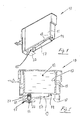
- the connecting piece 15 a the same over a predetermined height, here approximately half the height of the same extending ink supply channel 17 upstream, in particular, which is formed in the bottom 14 of the ink cartridge 10.
- This ink supply channel 17 is arranged sunk relative to the lower peripheral edge 18 of the housing 11 of the ink cartridge limiting end and side walls, in particular the Figures 2 . 4 and 5 very good.
- the ink supply channel 17 7 extends over about half the floor length. Furthermore, the Fig. 2 can be seen very well that the ink supply channel 17 is formed so that in use of the ink cartridge, that is, in a position in which the bottom 14 is below, which is located in the ink supply channel 17 ink gravitationally flows to the connecting piece 15 and ink discharge port 16 out , Concretely, the bottom 19 of the ink supply channel 17 drops toward port 15 and ink discharge port 16, respectively.
- the cross section of the ink supply channel 17 has a ratio of width "B" to depth "T" of less than 1 (B: T ⁇ 1), this ratio towards the port 15 and the ink discharge port 16 out reduced.
- B width of the ink supply channel 17
- the width "B" is approximately constant over the length and is about. 1.0 to 3.0 mm.
- the width thereof is about 0.1, in particular about 0.3 to 2.0 mm, said width decreases with increasing depth "T" of the ink supply channel 17, in particular decreases continuously.
- the ink discharge opening 16 is associated with a valve ball 21 elastically biased by a helical compression spring 20, by which the ink discharge opening 1 is kept closed when the cartridge is not in use. Only in use, the valve ball 21 is lifted from the ink removal port 16 by a plunger-type supply port of the ink jet printer, so that the desired fluid connection or ink connection between the cartridge and ink jet printer is made.
- the ink removal opening 16 is also additionally closed on the outside by a film 22 which is pierced before the first use, so that the ink removal opening is accessible from the outside. Again, it is an already known measure.
Abstract
Description
Die Erfindung betrifft eine Tintenpatrone gemäß dem Oberbegriff des Anspruches 1. Derartige Tintenpatronen sind allgemein bekannt. Es wird diesbezüglich nur beispielhaft auf die
All diesen Tintenpatronen ist gemeinsam, daß sie in eine Patronenaufnahme eines Tintenstrahldruckers einsetzbar sind. Für eine funktionssichere Tintenversorgung ist es erforderlich, daß die Tintenpatrone ein Unterdruck erzeugendes Element umfaßt, welches die Tinte ausreichend zurückhält, so daß die Tintenpatrone bei Stillstand nicht ausläuft. Andererseits muß die Tinte beim Gebrauch des Druckers in ausreichendem Maße nachfließen, so daß der Druckkopf während des Betriebes mit Tinte versorgt ist. In der Regel besteht das Unterdruck erzeugende Element aus einem Schwamm oder faserigen Material, welches innerhalb einer sogenannten Tintenspeicherkammer unmittelbar vor einem Auslaßstutzen zum Versorgungsanschluß des Tintenstrahldruckers angeordnet ist.All these ink cartridges have in common that they can be used in a cartridge receptacle of an inkjet printer. For a functionally reliable ink supply, it is required that the ink cartridge comprises a negative pressure generating member which sufficiently restrains the ink so that the ink cartridge does not leak at standstill. On the other hand, when the printer is in use, the ink must flow sufficiently so that the printhead is supplied with ink during operation. In general, the negative pressure generating element consists of a sponge or fibrous material, which is disposed within a so-called ink storage chamber immediately before an outlet to the supply port of the ink jet printer.
Zum Befüllen einer derartigen Tintenpatrone sind verschiedene Verfahren bekannt, zum Beispiel Befüllung unter Vakuum oder Zwangsbefüllung mit erhöhtem Druck. Bei all diesen Fülherfahren ist es unvermeidlich, daß kleinere Mengen Luft in Form von Blasen in der Patrone zurückbleiben. Geschieht dies im Bereich der Tintenzuführung nahe der Tintenentnahmeöffnung bzw. des Anschlußstutzens zur Herstellung einer Fluidverbindung zwischen der Tintenspeicherkammer und einem am Tintenstrahldrucker vorgesehenen Versorgungsanschluß, kann dies die Schreibqualität mindern oder gar zum Totalausfall führen.For filling such an ink cartridge, various methods are known, for example filling under vacuum or forced filling with increased pressure. In all these filling operations, it is inevitable that smaller amounts of air in the form of bubbles remain in the cartridge. If this occurs in the vicinity of the ink supply near the ink discharge opening or the connecting piece for establishing a fluid connection between the ink storage chamber and a supply connection provided on the inkjet printer, this can reduce the writing quality or even lead to total failure.
Bisher versucht man dieses Problem mit einer Vielzahl von Rillen gegen die Tintenentnahmeöffnung hin oder mit langen flachen Kanälen, zu lösen. Ab einer gewissen Blasengröße sind diese Maßnahmen jedoch meist wirkungslos. An dieser Stelle setzt die vorliegende Erfindung an.So far, one tries to solve this problem with a variety of grooves against the ink discharge opening or with long shallow channels to solve. From a certain bubble size, however, these measures are usually ineffective. At this point, the present invention begins.
Der vorliegenden Erfindung geht es also darum, eine Tintenpatrone der eingangs genannten Art zur Verfügung zu stellen, die so ausgebildet ist, daß eine Tintenversorgung durch Blasen, die sich beim Befüllen der Tintenpatrone in unterschiedlicher Größe ausbilden, nicht unterbrochen wird, und zwar auch dann nicht, wenn sich größere Blasen ausbilden.The present invention is therefore to provide an ink cartridge of the type mentioned, which is designed so that an ink supply by bubbles, which form when filling the ink cartridge in different sizes, is not interrupted, even then when larger bubbles form.
Diese Aufgabe wird erfindungsgemäß durch die kennzeichnenden Merkmale des Anspruches 1 gelöst, wobei bevorzugte Ausführungsformen und konstruktive Details in den Unteransprüchen beschrieben sind.This object is achieved by the characterizing features of claim 1, wherein preferred embodiments and structural details are described in the subclaims.
Durch den erfindungsgemäß im Boden der Patrone ausgebildeten Tintenversorgungskanal, der sich vorzugsweise über wenigstens die Hälfte bis drei Viertel der Bodenlänge erstreckt und in Richtung zum Anschlußstutzen bzw. zur Tintenentnahmeöffnung hin abfällt, können sich dort ausbildende Blasen problemlos unterströmt werden, so daß der Tintenzufluß zum Anschlußstutzen bzw. zur Tintenentnahmeöffnung hin aufrecht erhalten bleibt. Dabei sei darauf hingewiesen, daß der Tintenversorgungskanal vorzugsweise über seine gesamte Länge mit der Tintenspeicherkammer in Fluidverbindung steht, d.h. an seiner Oberseite offen ist. Wenn in der Tintenspeicherkammer sich ein Tintenspeicherelement in Form eines Schwamms oder Faserelements befindet, grenzt dieses unmittelbar an die offene Oberseite des Tintenversorgungskanals an. Etwaige Luftblasen sammeln sich dann an der Oberseite des Tintenversorgungskanals bzw. an der Unterseite des Tintenspeicherelements. Unterhalb dieser Blasen bleibt die Tintenversorgung des Anschlußstutzens bzw. der Tintenentnahmeöffnung aufrecht erhalten.By inventively formed in the bottom of the cartridge ink supply channel, which preferably extends over at least half to three quarters of the bottom length and drops toward the connection piece or the ink removal opening, there forming bubbles can be underflowed easily, so that the Tintenzufluß to the connection piece or up to the ink removal opening is maintained. It should be noted that the ink supply channel is preferably in fluid communication with the ink storage chamber over its entire length, i. is open at its top. If an ink storage element in the form of a sponge or fiber element is located in the ink storage chamber, this immediately adjoins the open top side of the ink supply channel. Any air bubbles will then accumulate at the top of the ink supply channel or at the bottom of the ink storage element. Below these bubbles, the ink supply of the connection piece or the ink discharge opening is maintained.
In einer weiterhin bevorzugten Ausführungsform weist der Querschnitt des Tintenversorgungskanals ein Verhältnis von Breite zu Tiefe von kleiner 1 auf, wobei sich diese Verhältniszahl in Richtung zur Tintenentnahmeöffnung hin verkleinert. Die Breite des Tintenversorgungskanals an seiner Oberseite ist vorzugsweise konstant und beträgt 1,0 bis 3,0 mm, wobei die Breite in Richtung zur Tiefe hin abnimmt. Vorzugsweise ist der Querschnitt des Tintenversorgungskanals etwa V-förmig ausgebildet.In a further preferred embodiment, the cross-section of the ink supply channel has a width to depth ratio of less than 1, this ratio decreasing towards the ink discharge opening. The width of the ink supply channel at its top is preferably constant and is 1.0 to 3.0 mm, the width decreasing in the direction of the depth. Preferably, the cross section of the ink supply channel is formed approximately V-shaped.
Auf diese Weise ist sichergestellt, daß alle Größen von Luftblasen die Tintenversorgung nicht unterbrechen können, da immer unterhalb einer solchen Blase noch genügend Querschnittsraum für die Tintenversorgung vorhanden ist.In this way, it is ensured that all sizes of air bubbles can not interrupt the supply of ink, as always below such a bubble enough cross-sectional space for the ink supply is available.
Dadurch, daß der Tintenversorgungskanal so ausgebildet ist, daß im Gebrauch der Tintenpatrone die sich im Tintenversorgungskanal befindliche Tinte schwerkraftbedingt zum Anschlußstutzen bzw. zur Tintenentnahmeöffnung hin fließt, wird eine nahezu vollständige Entleerung der Tintenpatrone, insbesondere auch einer wiederbefüllten Tintenpatrone gewährleistet. Bei einer konkreten Ausführungsform wird diese Maßnahme dadurch gelöst, daß der Grund des Tintenversorgungskanals in Richtung zum Anschlußstutzen bzw. zur Tintenentnahmeöffnung hin abfällt.Characterized in that the ink supply channel is formed so that in use of the ink cartridge which is located in the ink supply channel ink gravitationally flows to the connection piece or to the ink removal opening, an almost complete emptying of the ink cartridge, in particular a refilled ink cartridge is guaranteed. In a specific embodiment, this measure is achieved by the fact that the bottom of the ink supply channel in the direction of the connection piece or to the ink removal opening drops out.
Am Grund des Tintenversorgungskanals beträgt die Breite vorzugsweise zwischen etwa 0,1 bis 2,0 mm, wobei diese Breite mit zunehmender Tiefe des Tintenversorgungskanals abnimmt, insbesondere kontinuierlich abnimmt. Bei einem Tintenversorgungskanal mit V-förmigem Querschnitt, wird die vorgenannte Maßnahme zwangsläufig dann erreicht, wenn der Winkel zwischen den beiden Seitenwänden des Tintenversorgungskanals über die Länge konstant bleibt, der Grund des Tintenversorgungskanals jedoch in Richtung zum Anschlußstutzen bzw. zur Tintenentnahmeöffnung hin abfällt.At the bottom of the ink supply channel, the width is preferably between about 0.1 to 2.0 mm, which width decreases with increasing depth of the ink supply channel, in particular decreases continuously. In an ink supply channel having a V-shaped cross section, the above measure is inevitably achieved when the angle between the two side walls of the ink supply channel remains constant over the length, but the bottom of the ink supply channel drops toward the port or ink discharge port.
Nachstehend wird ein Ausführungsbeispiel einer erfindungsgemäß ausgebildeten Tintenpatrone anhand der beigefügten Zeichnung erläutert. Diese zeigt in:
- Fig. 1
- eine erfindungsgemäß ausgebildete Tintenpatrone in perspektivischer Ansicht von schräg unten;
- Fig. 2
- die Tintenpatrone gemäß
Fig. 1 im Längsschnitt; - Fig. 3
- die Tintenpatrone gemäß
Fig. 1 in Seitenansicht; - Fig. 4
- die Tintenpatrone gemäß
Fig. 3 im Schnitt längs Linie A-A; und - Fig. 5
- die Tintenpatrone gemäß
Fig. 3 im Schnitt längs Linie B-B.
- Fig. 1
- an inventively constructed ink cartridge in a perspective view obliquely from below;
- Fig. 2
- the ink cartridge according to
Fig. 1 in longitudinal section; - Fig. 3
- the ink cartridge according to
Fig. 1 in side view; - Fig. 4
- the ink cartridge according to
Fig. 3 in section along line AA; and - Fig. 5
- the ink cartridge according to
Fig. 3 in section along line BB.
In den
Von besonderer Bedeutung für die dargestellte Ausführungsform ist, daß dem Anschlußstutzen 15 ein sich über eine vorbestimmte Höhe desselben, hier etwa die halbe Höhe desselben erstreckender Tintenversorgungskanal 17 zu-, insbesondere vorgeordnet ist, der im Boden 14 der Tintenpatrone 10 ausgebildet ist. Dieser Tintenversorgungskanal 17 ist relativ zur unteren Umfangskante 18 der das Gehäuse 11 der Tintenpatrone begrenzenden Stirn- und Seitenwände versenkt angeordnet, wie insbesondere die
Wie weiterhin die
Wie bereits eingangs erwähnt und wie insbesondere den
Gemäß den
Bei der dargestellten Ausführungsform ist der Tintenentnahmeöffnung 16 eine durch eine Schraubendruckfeder 20 elastisch vorgespannte Ventilkugel 21 zugeordnet, durch die bei Nichtgebrauch der Patrone die Tintenentnahmeöffnung 1 verschlossen gehalten wird. Erst beim Gebrauch wird durch einen stößelartigen Versorgungsanschluß des Tintenstrahldruckers die Ventilkugel 21 von der Tintenentnahmeöffnung 16 abgehoben, so daß die gewünschte Fluidverbindung bzw. Tintenverbindung zwischen Patrone und Tintenstrahldrucker hergestellt ist.In the illustrated embodiment, the
Vor dem ersten Gebrauch ist die Tintenentnahmeöffnung 16 auch zusätzlich noch außenseitig durch eine Folie 22 verschlossen, die vor dem ersten Gebrauch aufgestochen wird, so daß die Tintenentnahmeöffnung von außen her zugänglich ist. Auch hier handelt es sich um eine an sich bereits bekannte Maßnahme.Before the first use, the ink removal opening 16 is also additionally closed on the outside by a
Sämtliche in den Anmeldungsunterlagen offenbarten Merkmale werden als erfindungswesentlich beansprucht, soweit sie einzeln oder in Kombination gegenüber dem Stand der Technik neu sind.All disclosed in the application documents features are claimed as essential to the invention, as far as they are new individually or in combination over the prior art.
- 1010
- Tintenpatroneink cartridge
- 1111
- Gehäusecasing
- 1212
- TintenspeicherkammerInk storage chamber
- 1313
- TintenspeicherelementInk member
- 1414
- Bodenground
- 1515
- Anschlußstutzenconnecting branch
- 1616
- TintenentnahmeöffnungInk removal opening
- 1717
- TintenversorgungskanalInk supply channel
- 1818
- untere Umfangskante des Gehäuseslower peripheral edge of the housing
- 1919
- Grund des TintenversorgungskanalsReason of the ink supply channel
- 2020
- Druckfeder (elastisches Element)Compression spring (elastic element)
- 2121
- Ventilkugelvalve ball
- 2222
- Verschlußfolieclosing film
Claims (8)
dadurch gekennzeichnet, daß
der Tintenentnahmeöffnung (16), insbesondere dem eine solche umfassenden Anschlußstutzen (15) ein sich über eine vorbestimmte Höhe desselben erstreckender Tintenversorgungskanal (17) zu-, insbesondere vorgeordnet ist, der im Boden (14) der Tintenpatrone (10) ausgebildet ist.An ink cartridge (10) for an ink jet printer, comprising a housing (11) delimiting at least one ink chamber (12) and an ink removal opening (16) on the underside or base (14) thereof, in particular a connecting piece (15) for producing the same a fluid connection between the ink chamber (12) and a provided at the ink jet printer supply terminal is formed,
characterized in that
the ink discharge opening (16), in particular to which such a comprehensive connection piece (15) to a predetermined height of the same extending ink supply channel (17), in particular upstream, which is formed in the bottom (14) of the ink cartridge (10).
dadurch gekennzeichnet, daß
der Tintenversorgungskanal (17) sich über wenigstens die Hälfte bis drei Viertel der Bodenlänge erstreckt.Ink cartridge according to claim 1,
characterized in that
the ink supply channel (17) extends over at least half to three quarters of the floor length.
dadurch gekennzeichnet, daß
der Tintenversorgungskanal (17) so ausgebildet ist, daß im Gebrauch der Tintenpatrone die sich im Tintenversargungskanal (17) befindliche Tinte schwerkraftbedingt zum Anschlußstutzen (15) bzw. zur Tintenentnahmeöffnung (16) hin fließt.Ink cartridge according to claim 1 or 2,
characterized in that
the ink supply passage (17) is formed so that, in use of the ink cartridge, the ink in the ink supply passage (17) flows toward the port (15) and the ink discharge port (16) by gravity.
dadurch gekennzeichnet, daß
der Grund (19) des Tintenversorgungskanals (17) in Richtung zum Anschlußstutzen (15) bzw. zur Tintenentnahmeöffnung (16) hin abfällt.Ink cartridge according to claim 3,
characterized in that
the bottom (19) of the ink supply passage (17) drops toward the port (15) and the ink discharge port (16), respectively.
dadurch gekennzeichnet, daß
der Querschnitt des Tintenversorgungskanals (17) ein Verhältnis von Breite (B) zu Tiefe (T) von kleiner als 1 aufweist, und sich dieses Verhältnis in Richtung zum Anschlußstutzen (15) bzw. zur Tintenentnahmeöffnung (16) hin verkleinert.An ink cartridge according to any one of claims 1 to 4,
characterized in that
the cross-section of the ink supply channel (17) has a ratio of width (B) to depth (T) of less than 1, and this ratio decreases toward the port (15) and the ink discharge port (16), respectively.
dadurch gekennzeichnet, daß
der Querschnitt des Tintenversorgungskanals (17) sich von oben nach unten, d.h. in Richtung zum Grund (19) desselben hin verkleinert, insbesondere etwa V-förmig ausgebildet ist.Ink cartridge according to one of claims 1 to 5,
characterized in that
the cross-section of the ink supply channel (17) is reduced from top to bottom, ie towards the base (19) thereof, in particular approximately V-shaped.
dadurch gekennzeichnet, daß
die Breite (B) an der Oberseite des Tintenversorgungskanals (17), über die dieser mit der Tintenkammer (12) kommuniziert, über dessen Länge konstant ist, und etwa 1,0 bis 3,0 mm beträgt.Ink cartridge according to claim 6,
characterized in that
the width (B) at the top of the ink supply channel (17) over which it communicates with the ink chamber (12), is constant over its length, and about 1.0 to 3.0 mm.
dadurch gekennzeichnet, daß
die Breite (B) des Tintenversorgungskanals (17) am Grund (19) desselben zwischen etwa 0,1 mm, insbesondere etwa 0,3 mm bis 2,00 mm beträgt, wobei diese Breite mit zunehmender Tiefe (T) des Tintenversorgungskanals (17) abnimmt, insbesondere kontinuierlich abnimmt.Ink cartridge according to claim 6 or 7,
characterized in that
the width (B) of the ink supply channel (17) at the base (19) thereof is between about 0.1 mm, in particular about 0.3 mm to 2.00 mm, this width increasing with increasing depth (T) of the ink supply channel (17) decreases, in particular decreases continuously.
Applications Claiming Priority (1)
| Application Number | Priority Date | Filing Date | Title |
|---|---|---|---|
| DE102007048820A DE102007048820A1 (en) | 2007-10-10 | 2007-10-10 | Ink cartridge for an inkjet printer |
Publications (2)
| Publication Number | Publication Date |
|---|---|
| EP2047998A2 true EP2047998A2 (en) | 2009-04-15 |
| EP2047998A3 EP2047998A3 (en) | 2010-09-08 |
Family
ID=40139298
Family Applications (1)
| Application Number | Title | Priority Date | Filing Date |
|---|---|---|---|
| EP08166303A Withdrawn EP2047998A3 (en) | 2007-10-10 | 2008-10-10 | Ink cartridge for an ink jet printer |
Country Status (4)
| Country | Link |
|---|---|
| US (1) | US20090096851A1 (en) |
| EP (1) | EP2047998A3 (en) |
| JP (1) | JP2009107334A (en) |
| DE (1) | DE102007048820A1 (en) |
Families Citing this family (5)
| Publication number | Priority date | Publication date | Assignee | Title |
|---|---|---|---|---|
| JP5728959B2 (en) * | 2010-03-25 | 2015-06-03 | セイコーエプソン株式会社 | Liquid container |
| JP5720148B2 (en) | 2010-09-03 | 2015-05-20 | セイコーエプソン株式会社 | Printing material cartridge and printing material supply system |
| US8857960B2 (en) | 2011-10-28 | 2014-10-14 | Hewlett-Packard Development Company, L.P. | Fluid supply housing |
| EP3099502B1 (en) | 2014-01-30 | 2018-03-07 | Hewlett-Packard Development Company, L.P. | Tri-color ink cartridge housing |
| EP3099503B1 (en) | 2014-01-30 | 2018-05-16 | Hewlett-Packard Development Company, L.P. | Tri-color ink cartridge |
Citations (4)
| Publication number | Priority date | Publication date | Assignee | Title |
|---|---|---|---|---|
| EP0879703A2 (en) | 1994-08-24 | 1998-11-25 | Canon Kabushiki Kaisha | Ink container for ink jet printer, holder for the container, carriage for the holder and ink jet printer |
| EP1481809A2 (en) | 2003-05-27 | 2004-12-01 | Pelikan Hardcopy Production AG | Ink cartridge |
| EP1547783A2 (en) | 2003-12-26 | 2005-06-29 | Canon Kabushiki Kaisha | Liquid container |
| EP1550558A1 (en) | 2003-12-29 | 2005-07-06 | Dynamic Cassette International Limited | A cartridge for a printer |
Family Cites Families (9)
| Publication number | Priority date | Publication date | Assignee | Title |
|---|---|---|---|---|
| JP2817657B2 (en) * | 1994-08-23 | 1998-10-30 | 富士ゼロックス株式会社 | Ink supply device and recording device |
| JP2002178541A (en) * | 2000-02-28 | 2002-06-26 | Seiko Epson Corp | Recording head unit |
| US6814433B2 (en) * | 2001-06-13 | 2004-11-09 | Nu-Kote International, Inc. | Base aperture in ink jet cartridge with irregular edges for breaking surface tension of the ink |
| US20040189755A1 (en) * | 2001-11-03 | 2004-09-30 | Studholme John William | Authentication of a remote user to a host in data communication system |
| KR100481518B1 (en) * | 2002-09-30 | 2005-04-07 | 삼성전자주식회사 | Ink cartridge |
| US6840609B2 (en) * | 2003-02-05 | 2005-01-11 | Microjet Technology, Ltd. | Structure of ink cartridge and method for producing the same |
| KR100612450B1 (en) * | 2004-10-14 | 2006-08-16 | 삼성전자주식회사 | Ink cartridge for the wide array type head |
| EP1772270B1 (en) * | 2005-09-29 | 2008-01-16 | Brother Kogyo Kabushiki Kaisha | Ink Cartridge |
| JP4793163B2 (en) * | 2005-11-30 | 2011-10-12 | セイコーエプソン株式会社 | Liquid container |
-
2007
- 2007-10-10 DE DE102007048820A patent/DE102007048820A1/en not_active Withdrawn
-
2008
- 2008-10-09 JP JP2008262662A patent/JP2009107334A/en active Pending
- 2008-10-10 US US12/249,039 patent/US20090096851A1/en not_active Abandoned
- 2008-10-10 EP EP08166303A patent/EP2047998A3/en not_active Withdrawn
Patent Citations (4)
| Publication number | Priority date | Publication date | Assignee | Title |
|---|---|---|---|---|
| EP0879703A2 (en) | 1994-08-24 | 1998-11-25 | Canon Kabushiki Kaisha | Ink container for ink jet printer, holder for the container, carriage for the holder and ink jet printer |
| EP1481809A2 (en) | 2003-05-27 | 2004-12-01 | Pelikan Hardcopy Production AG | Ink cartridge |
| EP1547783A2 (en) | 2003-12-26 | 2005-06-29 | Canon Kabushiki Kaisha | Liquid container |
| EP1550558A1 (en) | 2003-12-29 | 2005-07-06 | Dynamic Cassette International Limited | A cartridge for a printer |
Also Published As
| Publication number | Publication date |
|---|---|
| DE102007048820A1 (en) | 2009-04-16 |
| US20090096851A1 (en) | 2009-04-16 |
| EP2047998A3 (en) | 2010-09-08 |
| JP2009107334A (en) | 2009-05-21 |
Similar Documents
| Publication | Publication Date | Title |
|---|---|---|
| DE4425694C2 (en) | Continuous ink refill system for inkjet cartridges | |
| DE69725264T2 (en) | Container for dispensing liquid | |
| DE60032274T2 (en) | Liquid container, recording head and recorder provided therewith | |
| DE10306258B4 (en) | Ink cartridge with regulation of a fluid flow | |
| DE3313112C2 (en) | Inkjet printer | |
| DE3316970C2 (en) | ||
| DE4425693A1 (en) | Automatic ink refill system for disposable inkjet cartridges | |
| DE102006014283A1 (en) | liquid container | |
| DE3039166A1 (en) | INK PENS | |
| DE60022716T2 (en) | Ink jet printer with terminal block removes the bubbles automatically trapped in a filter | |
| DE3030795C2 (en) | ||
| DE3546462A1 (en) | Fuel vapour separation arrangement | |
| EP2047998A2 (en) | Ink cartridge for an ink jet printer | |
| DE3006726C2 (en) | Ink writing device | |
| DE102007040108A1 (en) | Apparatus for refilling an ink cartridge for an inkjet printer | |
| EP2214907B1 (en) | Ink cartridge, especially for an ink jet printer | |
| DE10315237A1 (en) | reservoir unit | |
| DE10324059B4 (en) | ink cartridge | |
| DE102006057090A1 (en) | Device to refilling ink cartridge for ink jet printer, has printing head comprising jets or has ink outlet opening coupled to inkjet of ink jet head | |
| DE3809187A1 (en) | RECORDING HEAD AND RECORDING DEVICE FOR INK-JET RECORDING | |
| DE60309427T2 (en) | Method for pressure control of an ink cartridge and pressure control device | |
| DE102006003055B4 (en) | ink tank | |
| DE202011002459U1 (en) | Adapter for removable insertion into an inkjet printer | |
| DE3736954C1 (en) | Ink line for a fountain pen | |
| EP1556224B1 (en) | Ink cartridge to be mounted on a recording head |
Legal Events
| Date | Code | Title | Description |
|---|---|---|---|
| PUAI | Public reference made under article 153(3) epc to a published international application that has entered the european phase |
Free format text: ORIGINAL CODE: 0009012 |
|
| AK | Designated contracting states |
Kind code of ref document: A2 Designated state(s): AT BE BG CH CY CZ DE DK EE ES FI FR GB GR HR HU IE IS IT LI LT LU LV MC MT NL NO PL PT RO SE SI SK TR |
|
| AX | Request for extension of the european patent |
Extension state: AL BA MK RS |
|
| PUAL | Search report despatched |
Free format text: ORIGINAL CODE: 0009013 |
|
| AK | Designated contracting states |
Kind code of ref document: A3 Designated state(s): AT BE BG CH CY CZ DE DK EE ES FI FR GB GR HR HU IE IS IT LI LT LU LV MC MT NL NO PL PT RO SE SI SK TR |
|
| AX | Request for extension of the european patent |
Extension state: AL BA MK RS |
|
| 17P | Request for examination filed |
Effective date: 20110111 |
|
| AKX | Designation fees paid |
Designated state(s): CH CZ DE FR GB LI |
|
| RAP1 | Party data changed (applicant data changed or rights of an application transferred) |
Owner name: PELIKAN HARDCOPY PRODUCTION AG |
|
| GRAP | Despatch of communication of intention to grant a patent |
Free format text: ORIGINAL CODE: EPIDOSNIGR1 |
|
| INTG | Intention to grant announced |
Effective date: 20130418 |
|
| STAA | Information on the status of an ep patent application or granted ep patent |
Free format text: STATUS: THE APPLICATION IS DEEMED TO BE WITHDRAWN |
|
| 18D | Application deemed to be withdrawn |
Effective date: 20130829 |