EP2047827A1 - Expandable reverse shoulder trail - Google Patents
Expandable reverse shoulder trail Download PDFInfo
- Publication number
- EP2047827A1 EP2047827A1 EP08166202A EP08166202A EP2047827A1 EP 2047827 A1 EP2047827 A1 EP 2047827A1 EP 08166202 A EP08166202 A EP 08166202A EP 08166202 A EP08166202 A EP 08166202A EP 2047827 A1 EP2047827 A1 EP 2047827A1
- Authority
- EP
- European Patent Office
- Prior art keywords
- insert
- proximal end
- end portion
- cup
- trial
- Prior art date
- Legal status (The legal status is an assumption and is not a legal conclusion. Google has not performed a legal analysis and makes no representation as to the accuracy of the status listed.)
- Granted
Links
Images






Classifications
-
- A—HUMAN NECESSITIES
- A61—MEDICAL OR VETERINARY SCIENCE; HYGIENE
- A61F—FILTERS IMPLANTABLE INTO BLOOD VESSELS; PROSTHESES; DEVICES PROVIDING PATENCY TO, OR PREVENTING COLLAPSING OF, TUBULAR STRUCTURES OF THE BODY, e.g. STENTS; ORTHOPAEDIC, NURSING OR CONTRACEPTIVE DEVICES; FOMENTATION; TREATMENT OR PROTECTION OF EYES OR EARS; BANDAGES, DRESSINGS OR ABSORBENT PADS; FIRST-AID KITS
- A61F2/00—Filters implantable into blood vessels; Prostheses, i.e. artificial substitutes or replacements for parts of the body; Appliances for connecting them with the body; Devices providing patency to, or preventing collapsing of, tubular structures of the body, e.g. stents
- A61F2/02—Prostheses implantable into the body
- A61F2/30—Joints
- A61F2/46—Special tools for implanting artificial joints
- A61F2/4684—Trial or dummy prostheses
-
- A—HUMAN NECESSITIES
- A61—MEDICAL OR VETERINARY SCIENCE; HYGIENE
- A61F—FILTERS IMPLANTABLE INTO BLOOD VESSELS; PROSTHESES; DEVICES PROVIDING PATENCY TO, OR PREVENTING COLLAPSING OF, TUBULAR STRUCTURES OF THE BODY, e.g. STENTS; ORTHOPAEDIC, NURSING OR CONTRACEPTIVE DEVICES; FOMENTATION; TREATMENT OR PROTECTION OF EYES OR EARS; BANDAGES, DRESSINGS OR ABSORBENT PADS; FIRST-AID KITS
- A61F2/00—Filters implantable into blood vessels; Prostheses, i.e. artificial substitutes or replacements for parts of the body; Appliances for connecting them with the body; Devices providing patency to, or preventing collapsing of, tubular structures of the body, e.g. stents
- A61F2/02—Prostheses implantable into the body
- A61F2/30—Joints
- A61F2/40—Joints for shoulders
-
- A—HUMAN NECESSITIES
- A61—MEDICAL OR VETERINARY SCIENCE; HYGIENE
- A61F—FILTERS IMPLANTABLE INTO BLOOD VESSELS; PROSTHESES; DEVICES PROVIDING PATENCY TO, OR PREVENTING COLLAPSING OF, TUBULAR STRUCTURES OF THE BODY, e.g. STENTS; ORTHOPAEDIC, NURSING OR CONTRACEPTIVE DEVICES; FOMENTATION; TREATMENT OR PROTECTION OF EYES OR EARS; BANDAGES, DRESSINGS OR ABSORBENT PADS; FIRST-AID KITS
- A61F2/00—Filters implantable into blood vessels; Prostheses, i.e. artificial substitutes or replacements for parts of the body; Appliances for connecting them with the body; Devices providing patency to, or preventing collapsing of, tubular structures of the body, e.g. stents
- A61F2/02—Prostheses implantable into the body
- A61F2/30—Joints
- A61F2/40—Joints for shoulders
- A61F2/4014—Humeral heads or necks; Connections of endoprosthetic heads or necks to endoprosthetic humeral shafts
-
- A—HUMAN NECESSITIES
- A61—MEDICAL OR VETERINARY SCIENCE; HYGIENE
- A61F—FILTERS IMPLANTABLE INTO BLOOD VESSELS; PROSTHESES; DEVICES PROVIDING PATENCY TO, OR PREVENTING COLLAPSING OF, TUBULAR STRUCTURES OF THE BODY, e.g. STENTS; ORTHOPAEDIC, NURSING OR CONTRACEPTIVE DEVICES; FOMENTATION; TREATMENT OR PROTECTION OF EYES OR EARS; BANDAGES, DRESSINGS OR ABSORBENT PADS; FIRST-AID KITS
- A61F2/00—Filters implantable into blood vessels; Prostheses, i.e. artificial substitutes or replacements for parts of the body; Appliances for connecting them with the body; Devices providing patency to, or preventing collapsing of, tubular structures of the body, e.g. stents
- A61F2/02—Prostheses implantable into the body
- A61F2/30—Joints
- A61F2002/30001—Additional features of subject-matter classified in A61F2/28, A61F2/30 and subgroups thereof
- A61F2002/30316—The prosthesis having different structural features at different locations within the same prosthesis; Connections between prosthetic parts; Special structural features of bone or joint prostheses not otherwise provided for
- A61F2002/30329—Connections or couplings between prosthetic parts, e.g. between modular parts; Connecting elements
- A61F2002/30331—Connections or couplings between prosthetic parts, e.g. between modular parts; Connecting elements made by longitudinally pushing a protrusion into a complementarily-shaped recess, e.g. held by friction fit
-
- A—HUMAN NECESSITIES
- A61—MEDICAL OR VETERINARY SCIENCE; HYGIENE
- A61F—FILTERS IMPLANTABLE INTO BLOOD VESSELS; PROSTHESES; DEVICES PROVIDING PATENCY TO, OR PREVENTING COLLAPSING OF, TUBULAR STRUCTURES OF THE BODY, e.g. STENTS; ORTHOPAEDIC, NURSING OR CONTRACEPTIVE DEVICES; FOMENTATION; TREATMENT OR PROTECTION OF EYES OR EARS; BANDAGES, DRESSINGS OR ABSORBENT PADS; FIRST-AID KITS
- A61F2/00—Filters implantable into blood vessels; Prostheses, i.e. artificial substitutes or replacements for parts of the body; Appliances for connecting them with the body; Devices providing patency to, or preventing collapsing of, tubular structures of the body, e.g. stents
- A61F2/02—Prostheses implantable into the body
- A61F2/30—Joints
- A61F2002/30001—Additional features of subject-matter classified in A61F2/28, A61F2/30 and subgroups thereof
- A61F2002/30316—The prosthesis having different structural features at different locations within the same prosthesis; Connections between prosthetic parts; Special structural features of bone or joint prostheses not otherwise provided for
- A61F2002/30329—Connections or couplings between prosthetic parts, e.g. between modular parts; Connecting elements
- A61F2002/30331—Connections or couplings between prosthetic parts, e.g. between modular parts; Connecting elements made by longitudinally pushing a protrusion into a complementarily-shaped recess, e.g. held by friction fit
- A61F2002/30332—Conically- or frustoconically-shaped protrusion and recess
-
- A—HUMAN NECESSITIES
- A61—MEDICAL OR VETERINARY SCIENCE; HYGIENE
- A61F—FILTERS IMPLANTABLE INTO BLOOD VESSELS; PROSTHESES; DEVICES PROVIDING PATENCY TO, OR PREVENTING COLLAPSING OF, TUBULAR STRUCTURES OF THE BODY, e.g. STENTS; ORTHOPAEDIC, NURSING OR CONTRACEPTIVE DEVICES; FOMENTATION; TREATMENT OR PROTECTION OF EYES OR EARS; BANDAGES, DRESSINGS OR ABSORBENT PADS; FIRST-AID KITS
- A61F2/00—Filters implantable into blood vessels; Prostheses, i.e. artificial substitutes or replacements for parts of the body; Appliances for connecting them with the body; Devices providing patency to, or preventing collapsing of, tubular structures of the body, e.g. stents
- A61F2/02—Prostheses implantable into the body
- A61F2/30—Joints
- A61F2002/30001—Additional features of subject-matter classified in A61F2/28, A61F2/30 and subgroups thereof
- A61F2002/30316—The prosthesis having different structural features at different locations within the same prosthesis; Connections between prosthetic parts; Special structural features of bone or joint prostheses not otherwise provided for
- A61F2002/30329—Connections or couplings between prosthetic parts, e.g. between modular parts; Connecting elements
- A61F2002/30405—Connections or couplings between prosthetic parts, e.g. between modular parts; Connecting elements made by screwing complementary threads machined on the parts themselves
- A61F2002/3042—Connections or couplings between prosthetic parts, e.g. between modular parts; Connecting elements made by screwing complementary threads machined on the parts themselves with a pin cooperating with a helical groove
-
- A—HUMAN NECESSITIES
- A61—MEDICAL OR VETERINARY SCIENCE; HYGIENE
- A61F—FILTERS IMPLANTABLE INTO BLOOD VESSELS; PROSTHESES; DEVICES PROVIDING PATENCY TO, OR PREVENTING COLLAPSING OF, TUBULAR STRUCTURES OF THE BODY, e.g. STENTS; ORTHOPAEDIC, NURSING OR CONTRACEPTIVE DEVICES; FOMENTATION; TREATMENT OR PROTECTION OF EYES OR EARS; BANDAGES, DRESSINGS OR ABSORBENT PADS; FIRST-AID KITS
- A61F2/00—Filters implantable into blood vessels; Prostheses, i.e. artificial substitutes or replacements for parts of the body; Appliances for connecting them with the body; Devices providing patency to, or preventing collapsing of, tubular structures of the body, e.g. stents
- A61F2/02—Prostheses implantable into the body
- A61F2/30—Joints
- A61F2002/30001—Additional features of subject-matter classified in A61F2/28, A61F2/30 and subgroups thereof
- A61F2002/30316—The prosthesis having different structural features at different locations within the same prosthesis; Connections between prosthetic parts; Special structural features of bone or joint prostheses not otherwise provided for
- A61F2002/30329—Connections or couplings between prosthetic parts, e.g. between modular parts; Connecting elements
- A61F2002/30476—Connections or couplings between prosthetic parts, e.g. between modular parts; Connecting elements locked by an additional locking mechanism
- A61F2002/30507—Connections or couplings between prosthetic parts, e.g. between modular parts; Connecting elements locked by an additional locking mechanism using a threaded locking member, e.g. a locking screw or a set screw
-
- A—HUMAN NECESSITIES
- A61—MEDICAL OR VETERINARY SCIENCE; HYGIENE
- A61F—FILTERS IMPLANTABLE INTO BLOOD VESSELS; PROSTHESES; DEVICES PROVIDING PATENCY TO, OR PREVENTING COLLAPSING OF, TUBULAR STRUCTURES OF THE BODY, e.g. STENTS; ORTHOPAEDIC, NURSING OR CONTRACEPTIVE DEVICES; FOMENTATION; TREATMENT OR PROTECTION OF EYES OR EARS; BANDAGES, DRESSINGS OR ABSORBENT PADS; FIRST-AID KITS
- A61F2/00—Filters implantable into blood vessels; Prostheses, i.e. artificial substitutes or replacements for parts of the body; Appliances for connecting them with the body; Devices providing patency to, or preventing collapsing of, tubular structures of the body, e.g. stents
- A61F2/02—Prostheses implantable into the body
- A61F2/30—Joints
- A61F2002/30001—Additional features of subject-matter classified in A61F2/28, A61F2/30 and subgroups thereof
- A61F2002/30316—The prosthesis having different structural features at different locations within the same prosthesis; Connections between prosthetic parts; Special structural features of bone or joint prostheses not otherwise provided for
- A61F2002/30535—Special structural features of bone or joint prostheses not otherwise provided for
- A61F2002/30537—Special structural features of bone or joint prostheses not otherwise provided for adjustable
- A61F2002/3055—Special structural features of bone or joint prostheses not otherwise provided for adjustable for adjusting length
-
- A—HUMAN NECESSITIES
- A61—MEDICAL OR VETERINARY SCIENCE; HYGIENE
- A61F—FILTERS IMPLANTABLE INTO BLOOD VESSELS; PROSTHESES; DEVICES PROVIDING PATENCY TO, OR PREVENTING COLLAPSING OF, TUBULAR STRUCTURES OF THE BODY, e.g. STENTS; ORTHOPAEDIC, NURSING OR CONTRACEPTIVE DEVICES; FOMENTATION; TREATMENT OR PROTECTION OF EYES OR EARS; BANDAGES, DRESSINGS OR ABSORBENT PADS; FIRST-AID KITS
- A61F2/00—Filters implantable into blood vessels; Prostheses, i.e. artificial substitutes or replacements for parts of the body; Appliances for connecting them with the body; Devices providing patency to, or preventing collapsing of, tubular structures of the body, e.g. stents
- A61F2/02—Prostheses implantable into the body
- A61F2/30—Joints
- A61F2002/30001—Additional features of subject-matter classified in A61F2/28, A61F2/30 and subgroups thereof
- A61F2002/30316—The prosthesis having different structural features at different locations within the same prosthesis; Connections between prosthetic parts; Special structural features of bone or joint prostheses not otherwise provided for
- A61F2002/30535—Special structural features of bone or joint prostheses not otherwise provided for
- A61F2002/30537—Special structural features of bone or joint prostheses not otherwise provided for adjustable
- A61F2002/30553—Special structural features of bone or joint prostheses not otherwise provided for adjustable for adjusting a position by translation along an axis
-
- A—HUMAN NECESSITIES
- A61—MEDICAL OR VETERINARY SCIENCE; HYGIENE
- A61F—FILTERS IMPLANTABLE INTO BLOOD VESSELS; PROSTHESES; DEVICES PROVIDING PATENCY TO, OR PREVENTING COLLAPSING OF, TUBULAR STRUCTURES OF THE BODY, e.g. STENTS; ORTHOPAEDIC, NURSING OR CONTRACEPTIVE DEVICES; FOMENTATION; TREATMENT OR PROTECTION OF EYES OR EARS; BANDAGES, DRESSINGS OR ABSORBENT PADS; FIRST-AID KITS
- A61F2/00—Filters implantable into blood vessels; Prostheses, i.e. artificial substitutes or replacements for parts of the body; Appliances for connecting them with the body; Devices providing patency to, or preventing collapsing of, tubular structures of the body, e.g. stents
- A61F2/02—Prostheses implantable into the body
- A61F2/30—Joints
- A61F2002/30001—Additional features of subject-matter classified in A61F2/28, A61F2/30 and subgroups thereof
- A61F2002/30316—The prosthesis having different structural features at different locations within the same prosthesis; Connections between prosthetic parts; Special structural features of bone or joint prostheses not otherwise provided for
- A61F2002/30535—Special structural features of bone or joint prostheses not otherwise provided for
- A61F2002/30594—Special structural features of bone or joint prostheses not otherwise provided for slotted, e.g. radial or meridian slot ending in a polar aperture, non-polar slots, horizontal or arcuate slots
-
- A—HUMAN NECESSITIES
- A61—MEDICAL OR VETERINARY SCIENCE; HYGIENE
- A61F—FILTERS IMPLANTABLE INTO BLOOD VESSELS; PROSTHESES; DEVICES PROVIDING PATENCY TO, OR PREVENTING COLLAPSING OF, TUBULAR STRUCTURES OF THE BODY, e.g. STENTS; ORTHOPAEDIC, NURSING OR CONTRACEPTIVE DEVICES; FOMENTATION; TREATMENT OR PROTECTION OF EYES OR EARS; BANDAGES, DRESSINGS OR ABSORBENT PADS; FIRST-AID KITS
- A61F2/00—Filters implantable into blood vessels; Prostheses, i.e. artificial substitutes or replacements for parts of the body; Appliances for connecting them with the body; Devices providing patency to, or preventing collapsing of, tubular structures of the body, e.g. stents
- A61F2/02—Prostheses implantable into the body
- A61F2/30—Joints
- A61F2002/30001—Additional features of subject-matter classified in A61F2/28, A61F2/30 and subgroups thereof
- A61F2002/30316—The prosthesis having different structural features at different locations within the same prosthesis; Connections between prosthetic parts; Special structural features of bone or joint prostheses not otherwise provided for
- A61F2002/30535—Special structural features of bone or joint prostheses not otherwise provided for
- A61F2002/30617—Visible markings for adjusting, locating or measuring
-
- A—HUMAN NECESSITIES
- A61—MEDICAL OR VETERINARY SCIENCE; HYGIENE
- A61F—FILTERS IMPLANTABLE INTO BLOOD VESSELS; PROSTHESES; DEVICES PROVIDING PATENCY TO, OR PREVENTING COLLAPSING OF, TUBULAR STRUCTURES OF THE BODY, e.g. STENTS; ORTHOPAEDIC, NURSING OR CONTRACEPTIVE DEVICES; FOMENTATION; TREATMENT OR PROTECTION OF EYES OR EARS; BANDAGES, DRESSINGS OR ABSORBENT PADS; FIRST-AID KITS
- A61F2/00—Filters implantable into blood vessels; Prostheses, i.e. artificial substitutes or replacements for parts of the body; Appliances for connecting them with the body; Devices providing patency to, or preventing collapsing of, tubular structures of the body, e.g. stents
- A61F2/02—Prostheses implantable into the body
- A61F2/30—Joints
- A61F2/40—Joints for shoulders
- A61F2/4014—Humeral heads or necks; Connections of endoprosthetic heads or necks to endoprosthetic humeral shafts
- A61F2002/4018—Heads or epiphyseal parts of humerus
- A61F2002/4022—Heads or epiphyseal parts of humerus having a concave shape, e.g. hemispherical cups
-
- A—HUMAN NECESSITIES
- A61—MEDICAL OR VETERINARY SCIENCE; HYGIENE
- A61F—FILTERS IMPLANTABLE INTO BLOOD VESSELS; PROSTHESES; DEVICES PROVIDING PATENCY TO, OR PREVENTING COLLAPSING OF, TUBULAR STRUCTURES OF THE BODY, e.g. STENTS; ORTHOPAEDIC, NURSING OR CONTRACEPTIVE DEVICES; FOMENTATION; TREATMENT OR PROTECTION OF EYES OR EARS; BANDAGES, DRESSINGS OR ABSORBENT PADS; FIRST-AID KITS
- A61F2/00—Filters implantable into blood vessels; Prostheses, i.e. artificial substitutes or replacements for parts of the body; Appliances for connecting them with the body; Devices providing patency to, or preventing collapsing of, tubular structures of the body, e.g. stents
- A61F2/02—Prostheses implantable into the body
- A61F2/30—Joints
- A61F2/40—Joints for shoulders
- A61F2/4014—Humeral heads or necks; Connections of endoprosthetic heads or necks to endoprosthetic humeral shafts
- A61F2002/4037—Connections of heads to necks
-
- A—HUMAN NECESSITIES
- A61—MEDICAL OR VETERINARY SCIENCE; HYGIENE
- A61F—FILTERS IMPLANTABLE INTO BLOOD VESSELS; PROSTHESES; DEVICES PROVIDING PATENCY TO, OR PREVENTING COLLAPSING OF, TUBULAR STRUCTURES OF THE BODY, e.g. STENTS; ORTHOPAEDIC, NURSING OR CONTRACEPTIVE DEVICES; FOMENTATION; TREATMENT OR PROTECTION OF EYES OR EARS; BANDAGES, DRESSINGS OR ABSORBENT PADS; FIRST-AID KITS
- A61F2/00—Filters implantable into blood vessels; Prostheses, i.e. artificial substitutes or replacements for parts of the body; Appliances for connecting them with the body; Devices providing patency to, or preventing collapsing of, tubular structures of the body, e.g. stents
- A61F2/02—Prostheses implantable into the body
- A61F2/30—Joints
- A61F2/40—Joints for shoulders
- A61F2/4014—Humeral heads or necks; Connections of endoprosthetic heads or necks to endoprosthetic humeral shafts
- A61F2002/4044—Connections of necks to shafts
-
- A—HUMAN NECESSITIES
- A61—MEDICAL OR VETERINARY SCIENCE; HYGIENE
- A61F—FILTERS IMPLANTABLE INTO BLOOD VESSELS; PROSTHESES; DEVICES PROVIDING PATENCY TO, OR PREVENTING COLLAPSING OF, TUBULAR STRUCTURES OF THE BODY, e.g. STENTS; ORTHOPAEDIC, NURSING OR CONTRACEPTIVE DEVICES; FOMENTATION; TREATMENT OR PROTECTION OF EYES OR EARS; BANDAGES, DRESSINGS OR ABSORBENT PADS; FIRST-AID KITS
- A61F2/00—Filters implantable into blood vessels; Prostheses, i.e. artificial substitutes or replacements for parts of the body; Appliances for connecting them with the body; Devices providing patency to, or preventing collapsing of, tubular structures of the body, e.g. stents
- A61F2/02—Prostheses implantable into the body
- A61F2/30—Joints
- A61F2/40—Joints for shoulders
- A61F2/4081—Glenoid components, e.g. cups
- A61F2002/4085—Glenoid components, e.g. cups having a convex shape, e.g. hemispherical heads
-
- A—HUMAN NECESSITIES
- A61—MEDICAL OR VETERINARY SCIENCE; HYGIENE
- A61F—FILTERS IMPLANTABLE INTO BLOOD VESSELS; PROSTHESES; DEVICES PROVIDING PATENCY TO, OR PREVENTING COLLAPSING OF, TUBULAR STRUCTURES OF THE BODY, e.g. STENTS; ORTHOPAEDIC, NURSING OR CONTRACEPTIVE DEVICES; FOMENTATION; TREATMENT OR PROTECTION OF EYES OR EARS; BANDAGES, DRESSINGS OR ABSORBENT PADS; FIRST-AID KITS
- A61F2220/00—Fixations or connections for prostheses classified in groups A61F2/00 - A61F2/26 or A61F2/82 or A61F9/00 or A61F11/00 or subgroups thereof
- A61F2220/0025—Connections or couplings between prosthetic parts, e.g. between modular parts; Connecting elements
-
- A—HUMAN NECESSITIES
- A61—MEDICAL OR VETERINARY SCIENCE; HYGIENE
- A61F—FILTERS IMPLANTABLE INTO BLOOD VESSELS; PROSTHESES; DEVICES PROVIDING PATENCY TO, OR PREVENTING COLLAPSING OF, TUBULAR STRUCTURES OF THE BODY, e.g. STENTS; ORTHOPAEDIC, NURSING OR CONTRACEPTIVE DEVICES; FOMENTATION; TREATMENT OR PROTECTION OF EYES OR EARS; BANDAGES, DRESSINGS OR ABSORBENT PADS; FIRST-AID KITS
- A61F2220/00—Fixations or connections for prostheses classified in groups A61F2/00 - A61F2/26 or A61F2/82 or A61F9/00 or A61F11/00 or subgroups thereof
- A61F2220/0025—Connections or couplings between prosthetic parts, e.g. between modular parts; Connecting elements
- A61F2220/0033—Connections or couplings between prosthetic parts, e.g. between modular parts; Connecting elements made by longitudinally pushing a protrusion into a complementary-shaped recess, e.g. held by friction fit
-
- A—HUMAN NECESSITIES
- A61—MEDICAL OR VETERINARY SCIENCE; HYGIENE
- A61F—FILTERS IMPLANTABLE INTO BLOOD VESSELS; PROSTHESES; DEVICES PROVIDING PATENCY TO, OR PREVENTING COLLAPSING OF, TUBULAR STRUCTURES OF THE BODY, e.g. STENTS; ORTHOPAEDIC, NURSING OR CONTRACEPTIVE DEVICES; FOMENTATION; TREATMENT OR PROTECTION OF EYES OR EARS; BANDAGES, DRESSINGS OR ABSORBENT PADS; FIRST-AID KITS
- A61F2250/00—Special features of prostheses classified in groups A61F2/00 - A61F2/26 or A61F2/82 or A61F9/00 or A61F11/00 or subgroups thereof
- A61F2250/0004—Special features of prostheses classified in groups A61F2/00 - A61F2/26 or A61F2/82 or A61F9/00 or A61F11/00 or subgroups thereof adjustable
- A61F2250/0007—Special features of prostheses classified in groups A61F2/00 - A61F2/26 or A61F2/82 or A61F9/00 or A61F11/00 or subgroups thereof adjustable for adjusting length
-
- A—HUMAN NECESSITIES
- A61—MEDICAL OR VETERINARY SCIENCE; HYGIENE
- A61F—FILTERS IMPLANTABLE INTO BLOOD VESSELS; PROSTHESES; DEVICES PROVIDING PATENCY TO, OR PREVENTING COLLAPSING OF, TUBULAR STRUCTURES OF THE BODY, e.g. STENTS; ORTHOPAEDIC, NURSING OR CONTRACEPTIVE DEVICES; FOMENTATION; TREATMENT OR PROTECTION OF EYES OR EARS; BANDAGES, DRESSINGS OR ABSORBENT PADS; FIRST-AID KITS
- A61F2250/00—Special features of prostheses classified in groups A61F2/00 - A61F2/26 or A61F2/82 or A61F9/00 or A61F11/00 or subgroups thereof
- A61F2250/0004—Special features of prostheses classified in groups A61F2/00 - A61F2/26 or A61F2/82 or A61F9/00 or A61F11/00 or subgroups thereof adjustable
- A61F2250/0008—Special features of prostheses classified in groups A61F2/00 - A61F2/26 or A61F2/82 or A61F9/00 or A61F11/00 or subgroups thereof adjustable for adjusting a position by translation along an axis or two perpendicular axes
-
- A—HUMAN NECESSITIES
- A61—MEDICAL OR VETERINARY SCIENCE; HYGIENE
- A61F—FILTERS IMPLANTABLE INTO BLOOD VESSELS; PROSTHESES; DEVICES PROVIDING PATENCY TO, OR PREVENTING COLLAPSING OF, TUBULAR STRUCTURES OF THE BODY, e.g. STENTS; ORTHOPAEDIC, NURSING OR CONTRACEPTIVE DEVICES; FOMENTATION; TREATMENT OR PROTECTION OF EYES OR EARS; BANDAGES, DRESSINGS OR ABSORBENT PADS; FIRST-AID KITS
- A61F2250/00—Special features of prostheses classified in groups A61F2/00 - A61F2/26 or A61F2/82 or A61F9/00 or A61F11/00 or subgroups thereof
- A61F2250/0058—Additional features; Implant or prostheses properties not otherwise provided for
- A61F2250/0096—Markers and sensors for detecting a position or changes of a position of an implant, e.g. RF sensors, ultrasound markers
- A61F2250/0097—Visible markings, e.g. indicia
Definitions
- the present invention relates to an expandable reverse shoulder trial for reverse shoulder athroplasty (RSA), and in particular it relates to such a trial including an insert that rotatably engages a humeral cup.
- RSA reverse shoulder athroplasty
- Dislocation can often be more difficult than reduction and RSA patients often have compromised bone stock and/or soft tissue.
- the extreme force required to dislocate the joint again may put the patient at risk for other injury and soft tissue trauma.
- current systems require the surgeon to use a trial and error approach in establishing proper soft tissue tension. This often takes several attempts before adequate stability is achieved.
- an adjustable trial including an insert that rotatably engages a humeral cup.
- the insert may first be inserted into the humeral cup and then rotated into a fully collapsed or neutral position. Such a device may allow a surgeon to easily reduce the shoulder joint.
- the insert may then be advanced to a position where optimal deltoid tension is achieved.
- the insert and humeral cup are preferably calibrated such that the surgeon may determine a liner thickness corresponding to a dialed position of the insert with respect to the humeral cup.
- dialed position or "dial in” indicate the distance between a proximal end of the insert and a proximal end of the humeral cup. This distance or liner thickness is measured by indications on the insert, such as calibration marks and/or attachment locations in reference to a marker on the humeral cup. This will be further explained in the detailed description.
- the surgeon may also perform range of motion ("ROM") and joint stability analyses during calibration of the trial. Preferably, the surgeon may then easily collapse the trial back to the neutral position and simply dislocate the joint. Further, the trial may also be preferably expanded prior to joint reduction and collapsed prior to joint dislocation repeatedly, depending on surgeon preference.
- a surgeon preferably records the dialed position of the expanded trial. This measurement should preferably be the liner thickness. If this measurement does not correspond to the size of a particular liner in the system, the surgeon may select a next larger sized liner. At this time, the surgeon may remove the trial and then implant a prosthesis including a humeral cup and the selected liner.
- the present invention greatly eases the reduction and dislocation of a shoulder joint during trialing because the surgeon may custom fit a trial to a patient after the joint has been reduced. This will greatly decrease the patient's exposure to intraoperative soft or hard tissue injuries related to extreme forces required to reduce and dislocate the joint. Moreover, the preferred one-step trialing approach of the present invention will also decrease surgical time, which is healthier for the patient and more efficient for the surgeon and hospital. Preferably, the expandable trial also decreases the size and cost of the overall instrument set, since only one trial per glenosphere diameter is generally required.
- a main distinguishing characteristic of the adjustable trial from prior art devices is the fact that an insert may be first inserted into a humeral cup and then rotated into a collapsed or neutral position. This preferably allows the surgeon to easily reduce the joint.
- the trial, including the insert and humeral cup may then be expanded into a second position wherein optimal deltoid tension is preferably achieved.
- the trial is calibrated such that the surgeon can determine which liner thickness corresponds to the dialed position on the trial.
- the surgeon can easily collapse the trial back to the neutral position and simply dislocate the joint.
- the trial may also be expanded prior to joint reduction and collapsed prior to joint dislocation repeatedly, depending on surgeon preference.
- the purpose of the present invention is to allow the surgeon to reduce the reverse shoulder trial and surrounding soft tissues into a relaxed state and/or dislocate a reduced shoulder joint while in a relaxed state. This will greatly ease the reduction of the joint.
- the surgeon may then "dial in” the appropriate liner thickness to achieve proper soft tissue tension.
- the trial is preferably designed to expand in discreet increments which correspond to liner prostheses that are available in multiple thicknesses. After a liner prosthesis is selected, it is then implanted with a humeral cup prosthesis.
- Step 1 Resect the proximal humerus at a height determined by a typical humeral resection guide and surgical technique. At this point the surgeon may move to glenoid preparation (step 5) or continue with humerus preparation.
- Step 2 Prepare the humerus distally in a standard fashion first using intramedullary reamers of increasing size according to surgeon preference.
- Step 3 Prepare the proximal humerus using broaches of increasing size. Preferably, starting with a broach that is smaller than the final prosthesis based on preoperative templating.
- Step 4 Perform calcar planing to prepare the proximal humerus to ensure proper seating of a humeral cup into the humeral stem and/or perform proximal reaming to create a seat for the cup.
- a trial humeral cup may also be inserted to assess seating and interference. The cup trial should be removed prior to preparing the glenoid surface.
- Step 5 Target the center of the glenoid using the centering guide and drill a centering hole. Insert a guidewire or guide pin into the centering hole and ream the glenoid face progressively until sub-chondral bone is thoroughly exposed.
- Step 6 Place and attach a baseplate on the glenoid face in a desired location.
- Step 7 Select an appropriate glenosphere trial and attach to the baseplate.
- Step 8 Select an expanding trial including an insert having a recess diameter matching the glenosphere trial diameter. Ensure that the expanding trial is in the fully collapsed or neutral position and insert the trial assembly into a tapered bore in the humeral broach or stem. The joint may now be reduced into a laxed state. Deltoid and remaining cuff tension can then be dialed in by expanding the trial. Laxity, ROM and stability can now be evaluated with the trial components in place. Trialing can also be accomplished by repeatedly reducing the shoulder joint at a specific thickness which the surgeon has dialed in, evaluating the fit and function, collapsing the trial, and dislocating the shoulder.
- Step 9 If different components (diameter etc.) are desired, substitutions may be made prior to implanting the prostheses.
- the dialed thickness of the expanded trial is preferably recorded. This measurement preferably will be the thickness of the liner prosthesis.
- Step 10 Remove the trial and implant the prostheses.
- proximal means closer to the heart and the term “distal” means more distant from the heart.
- distal means more distant from the heart.
- inferior means lower or bottom and the term “superior” means upper or top.
- anterior means towards the front part of the body or the face and the term “posterior” means towards the back of the body.
- medial means toward the midline of the body and the term “lateral” means away from the midline of the body.
- a first aspect of the present invention is an expandable shoulder trial having an insert including a proximal end and a distal end, the proximal end having a concave recess therein.
- the distal end of the insert includes a shaft, the shaft having a helical groove disposed on at least a portion thereof.
- the trial further includes a humeral cup having a proximal end including a recess therein, the recess defined by a circular wall for securing the insert shaft.
- a guide pin preferably protrudes from the circular wall into the recess, the guide pin adapted to engage the helical groove of the shaft of the insert.
- the proximal end of the insert may be rotatably adjusted in a first axial direction toward the proximal end of the humeral cup to collapse the trial and alternatively in an opposite second axial direction away from the proximal end of the humeral cup to expand the trial.
- the helical groove of the shaft preferably allows the insert when rotated to move in the first and second axial directions as the insert is rotated in only a first direction (i.e. clockwise or counter-clockwise direction).
- a first direction i.e. clockwise or counter-clockwise direction.
- the thickness and/or axial distance between the proximal end of humeral cup and the proximal end of the insert is adjusted by rotating the insert in either the first and or the second directions.
- the proximal end of the insert preferably includes an outer face having a plurality of calibration marks arranged thereon.
- the outer face of the insert preferably includes a plurality of attachment locations adapted to engage an adjustment tool for rotating the insert.
- the proximal end of the humeral cup includes a front face having a marker arranged thereon.
- the axial distance between the proximal end of humeral cup and the proximal end of the insert is indicated by the calibration marks on the insert in reference to the marker on the humeral cup.
- the trial of the present invention may also be provided as an expandable shoulder trial including a humeral cup having an axis, the humeral cup including a recess defining a substantially circular wall about the axis, the circular wall having a guide portion extending outwardly therefrom.
- the trial further includes an insert having a proximal end and a distal end, the proximal end of the insert having a concave recess disposed thereon, the distal end having a shaft extending therefrom towards the proximal end, the shaft of the insert preferably received in the recess of the cup.
- the shaft includes a helical groove disposed on at least a portion thereof.
- the guide portion is adapted to engage the helical groove of the shaft so that when the insert is rotatably adjusted the insert may move from a neutral position wherein the proximal end of the insert is substantially adjacent to the proximal end of the humeral cup, and into an expanded position wherein the proximal end of the insert is further away from the proximal end of the cup in the axial direction.
- a second aspect of the present invention is an expandable shoulder trial including a humeral cup having a distal end portion coupled to a stem, the humeral cup further including a proximal end portion having a base and a circular wall defining a circular recess, the wall having a guide pin protruding therefrom.
- the trial further includes an insert having a proximal end portion and a distal end portion for insertion in the circular recess of the humeral cup, the distal end portion having a cam track extending toward the proximal end portion, the cam track adapted to receive the guide pin of the humeral cup.
- the insert is rotatably adjustable along an axis in a first direction such that the distal end portion of the insert moves toward the base of the recess of the humeral cup.
- the insert is rotatably adjustable along the axis in an opposite second direction wherein the distal end of the insert moves away from the base of the recess of the humeral cup.
- the insert may be rotated in the first direction approximately 60° to reduce the distance between the proximal end of the humeral cup and the proximal end of the insert approximately 2mm.
- the insert includes an incremental stopping portion every 60° along the guide portion or cam-track of the shaft portion of the insert.
- the guide pin of the humeral cup may engage an incremental stopping portion of the insert. This may stop the insert from further rotation until a force great enough to overcome the friction between the guide pin and the incremental stopping portion is produced.
- the present invention is an expandable reverse shoulder trial for RSA.
- the trial is designed to take the place of a kit of trials and to provide the surgeon with greater intraoperative flexibility and ease of trialing during RSA.
- Prior art devices include trials of increasing thicknesses in "kit" form.
- Figure 1A is an isometric view of a humeral cup according to an embodiment of the present invention.
- Figure 1B is a front view of the humeral cup according to Figure 1A .
- Figure 1c is a side view of the humeral cup according to Figure 1A .
- Figure 1D is a bottom view of the humeral cup according to Figure 1A .
- Figure 2A is an isometric view of an alternative embodiment of a humeral cup according to the present invention.
- Figure 2B is a front view of the humeral cup according to Figure 2A .
- Figure 2C is a side view of the humeral cup according to Figure 2A .
- Figure 2D is a bottom view of the humeral cup according to Figure 2A .
- Figure 3A is an isometric view of an insert according to an embodiment of the present invention.
- Figure 3B is a front view of the insert according to Figure 3A .
- Figure 3C is a side view of the insert according to Figure 3A .
- Figure 4A is a side view of an alternative embodiment of an insert according to the present invention.
- Figure 4B is a side view of the insert according to Figure 4A rotated to the left.
- Figure 4C is a detail view A of a section of the insert according to Figure 4B .
- Figure 5A is an isometric view of an alternative embodiment of an insert of the present invention.
- Figure 5B is a front view of the insert according to Figure 5A .
- Figure 5C is a side view of the insert according to Figure 5A .
- Figure 5D is a side view of the insert similar to Figure 5C but rotated to the left.
- Figure 6A is a side view of an alternative embodiment of an insert according to the present invention.
- Figure 6B is a side view of the insert according to Figure 6A rotated to the left.
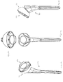
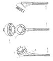
- Figure 7A is an isometric view of an adjustment tool according to an embodiment of the present invention.
- Figure 7B is a front view of the adjustment tool according to Figure 7A rotated 180°.
- Figure 7C is a side view of the adjustment tool according to Figure 7A from the left side.
- Figure 8 shows an axis of the humeral cup of Figure 2A aligned with an axis of the insert of Figure 5A prior to assembly.
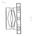
- Figure 9A is an assembled view of the humeral cup of Figure 1A and the insert of Figure 3A in a fully collapsed or neutral position.
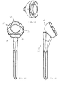
- Figure 9B is an assembled isometric view of the humeral cup and insert of Figure 9A assembled to an exemplary humeral stem.
- Figure 9C is an assembled front view of the humeral cup, insert, and humeral stem according to Figure 9B .
- Figure 9D is an assembled side view of the humeral cup, insert, and humeral stem according to Figure 9C .
- Figure 10A is an assembled view of the humeral cup of Figure 1A and the insert of Figure 3A in an expanded position.
- Figure 10B is an assembled isometric view of the humeral cup and insert of Figure 10A assembled to an exemplary humeral stem.
- Figure 10C is an assembled front view of the humeral cup, insert, and humeral stem according to Figure 10B .
- Figure 10D is an assembled side view of the humeral cup, insert, and humeral stem according to Figure 10C .
- Figure 11A is an assembled view of the humeral cup of Figure 2A and the insert of Figure 3A in a fully collapsed or neutral position.
- Figure 11B is an assembled front view of the humeral cup and insert of Figure 11A assembled to an exemplary humeral stem.
- Figure 11C is an assembled side view of the humeral cup, insert, and humeral stem according to Figure 11B .
- Figure 12A is an assembled view of the humeral cup of Figure 2A and the insert of Figure 3A in an expanded position.
- Figure 12B is an assembled front view of the humeral cup and insert of Figure 12A assembled to an exemplary humeral stem.
- Figure 12C is an assembled side view of the humeral cup, insert, and humeral stem according to Figure 12B .
- Figure 13A is an assembled view of the humeral cup of Figure 2A and the insert of Figure 5A in a fully collapsed or neutral position.
- Figure 13B is an assembled front view of the humeral cup and insert of Figure 13A assembled to an exemplary humeral stem.
- Figure 13C is an assembled side view of the humeral cup, insert, and humeral stem according to Figure 13B .
- Figure 14A is an assembled view of the humeral cup of Figure 2A and the insert of Figure 5A in an expanded position.
- Figure 14B is an assembled front view of the humeral cup and insert of Figure 14A assembled to an exemplary humeral stem.
- Figure 14C is an assembled side view of the humeral cup, insert, and humeral stem according to Figure 14B .
- cup 10 includes a proximal end 12 and a distal end 14.
- Cup 10 preferably further includes a circular wall 16 and a base 18 defining a recess 20.
- Recess 20 defines a central axis 22 as shown in Fig. 1C .
- a guide portion 23 protrudes from wall 16.
- Guide portion 23 is preferably configured as a pin.
- proximal end 12 and distal end 14 of cup 10 are not coplanar. Between distal end surface 14 and proximal end surface 12 is a hemispherical outer surface 24.
- a cup 10' further includes a concave surface 26 located between a proximal end surface 12' and a distal end surface 14'. Surface 26 faces medially and is preferably configured to allow for greater articulation of cup 10' with respect to a scapula bone after cup 10' has been trialed in the body.
- Cups 10 and 10' generally include all of the same features except for cup 10' including concave surface 26 and a partially hemispherical outer surface 24'.
- surface 26 may include a bore 28' associated therewith. Bore 28' may initially extend from surface 26 through wall 16' into recess 20'. Generally, bore 28' is configured to receive the guide pin 23' therein. Preferably, guide pin 23' has an end which protrudes outwardly from wall 16' into recess 20'. After guide pin 23' is located in position, such as shown generally in Figs. 2A-2C , bore 28' may be filled such that surface 26 is a curved flat surface throughout.
- distal end 14, 14' of cup 10, 10' includes a trunion 30, 30' protruding distally therefrom.
- Trunion 30 is preferably configured to mate with a corresponding bore in a proximal end of a humeral stem 80 as shown for example in Figs. 9A-9D .
- trunion 30, 30' has a male taper that may easily be secured to the corresponding tapered bore of humeral stem 80.
- Other quick-connect mechanisms known in the art may be used to connect cup 10, 10' to a humeral stem, for example, threaded connections, other pressure-fit connections, and clasps.
- Proximal end 12, 12' of cup 10, 10' preferably has a substantially flat proximal surface portion 32, 32'.
- proximal surface portion 32, 32' includes a central rounded edge 34, 34' which blends with wall 16, 16' and has a rounded edge 36, 36' which blends with outer surface 24, 24'.
- surface 32, 32' of humeral cup 10, 10' includes a marker 38, 38' arranged thereon.
- Marker 38, 38' is preferably of any configuration that gives a user, such as a surgeon or other operating room personnel, a visual frame of reference for the position of an insert with respect to humeral cup 10, 10'.
- insert 40 includes a proximal end portion 42 and a distal end 44 portion, the proximal end portion 42 having a proximal surface 52 including a proximally facing concave recessed surface 46 therein.
- distal end portion 44 of insert 40 includes a shaft 48, the shaft having a helical groove 50 disposed on at least a portion thereof.
- Guide pin 23, 23' protruding from circular wall 16, 16' into recess 20, 20' is configured to engage helical groove 50 of shaft 48 such that while guide pin 23, 23' is engaged with helical groove 50 at least a portion of shaft 48 is located within recess 20, 20'.
- an alternative embodiment of insert 40 may include a plurality of incremental stopping features or indents 51 along groove 50.
- each indent 51 is located approximately every 60° along groove 50.
- Indent 51 is configured to stop insert 40 from further rotation until a force great enough to overcome the friction between guide pin 23, 23' and indent 51 is produced.
- insert 40 may be rotatably adjusted about axis 22 by rotating in a first direction D1 as generally depicted on Fig. 3A , such that insert 40 may move into recess 20, 20' of humeral cup 10, 10'.
- insert 40 may be rotatably adjusted about axis 22 in an opposite second direction D2, such that insert 40 may move out of recess 20, 20' of humeral cup 10, 10'.
- the axial distance between proximal end 12, 12' of humeral cup 10, 10' and proximal surface 52 of proximal end portion 42 of insert 40 is adjusted along axis 22 by rotating insert 40 in either first and/or second directions D1, D2.
- proximal end surface 52 preferably includes a plurality of calibration marks 54 arranged thereon.
- proximal end portion 42 of insert 40 further includes a plurality of alternating convex and concave side faces, 56 and 58 respectively.
- calibration marks 54 may extend from proximal surface 52 onto side faces 56, 58.
- Side faces 56, 58 may further include a plurality of attachment locations 60 therein.
- attachment locations 60 are adapted to receive an adjustment tool 61 shown generally in Figs. 7A-7C . A surgeon or any other operating room personnel may use adjustment tool 61 to rotate insert 40 along axis 22 in either the first and/or second directions D1, D2.
- adjustment tool 61 includes a handle portion 62 having a shaft 64 protruding therefrom, the shaft having a tip 66 protruding therefrom.
- Handle portion 62 may further include a knurled portion 68 for easy gripping. It is contemplated by the present invention that tool 61 may have many alternative configurations.
- Tool 61 is an exemplary instrument for easily rotating insert 40 along axis 22 in either the first and/or second directions D1, D2.
- calibration marks 54 of insert 40 may also be arranged on side faces 56, 58.
- the axial distance between proximal end 12, 12' of humeral cup 10, 10' and surface 52 of proximal end portion 42 of insert 40 is measured by calibration marks 54 on any of surfaces 52, 56, and 58 of insert 40 in reference to marker 38, 38' of humeral cup 10, 10'.
- marker 38, 38' of humeral cup 10, 10' may be lined up with one of the calibration marks 54 of insert 40.
- insert 40 may then be rotated in direction D1 approximately 60° to reduce the distance between proximal end 12, 12' of humeral cup 10, 10' and proximal end surface 52 of insert 40 approximately 2mm.
- Insert 40 may then be rotated another 60° in direction D1 until a second calibration mark 54 to the left of the calibration mark 54 is now instead lined up with marker 38, 38' of humeral cup 10, 10'.
- the distance between proximal end 12, 12' of humeral cup 10, 10' and proximal end surface 52 of insert 40 would be further reduced approximately 2mm for a total of 4mm.
- the distance between calibration marks may be less than or greater than 60° apart.
- calibration marks are between 30° and 120° apart. More preferably, calibration marks are between 30° and 60° apart.
- the pitch of groove 50 determines the distance that insert 40 collapses or expands between calibration marks.
- the distance between proximal end 12, 12' of humeral cup 10, 10' and proximal end surface 52 of insert 40 may be reduced or expanded .5mm to 4mm between calibration marks 54.
- an exact number of calibration marks 54 would not be needed to indicate a distance X that insert 40 may travel in moving from the fully collapsed or neutral position as shown for example in Figs.
- attachment locations 60 may be located between calibration marks 54. In this case, the surgeon may approximate the distance insert 40 has collapsed or expanded.
- insert 40 may collapse and/or expand between 0 and 12mm. More preferably, insert 40 may collapse or expand 6mm. It is contemplated in the present invention that more or less than six calibration marks 54 may be arranged on insert 40.
- a concave side face 58 of insert 40 is configured to align with surface 26 of humeral cup 10'. It is within the scope of the present invention for one of convex surfaces 56 of insert 40 to be located adjacent to bottom surface 26 as well.
- insert 40 of the present invention is designated generally by reference numeral 40' as shown in Figures 5A-5D .
- insert 40' includes a proximal end portion 42' and a distal end portion 44', the proximal end portion 42' having a proximal surface 52' including a proximally facing concave recessed surface 46' therein.
- distal end portion 44' of insert 40' includes a shaft 48' having a helical groove 50' disposed on at least a portion thereof.
- Guide pin 23, 23' protruding from circular wall 16, 16' into recess 20, 20' is configured to engage helical groove 50' of shaft 48' such that while guide pin 23, 23' is engaged with helical groove 50' at least a portion of shaft 48' is located within recess 20, 20'.
- an alternative embodiment of insert 40' may include a plurality of incremental stopping features or indents 51' along groove 50'.
- each indent 51' is located approximately every 60° along groove 50'.
- 10' may engage an indent 51' of insert 40'.
- Indent 51' is configured to stop insert 40' from further rotation until a force great enough to overcome the friction between guide pin 23, 23' and indent 51' is produced.
- helical groove 50' of shaft 48' of insert 40' preferably allows proximal end portion 42' of insert 40' to move away from proximal end 12, 12' of humeral cup 10, 10' and thereafter toward proximal end 12, 12' of humeral cup 10, 10' as insert 40' is rotated in only the first direction D1.
- insert 40' is in the fully collapsed or neutral position as shown in Figs. 13A-13C , generally defined by shaft 48' of insert 40' being fully seated in recess 20, 20' a surgeon or other operating room personnel may rotate insert 40' in first direction D1.
- proximal surface 52' includes a plurality of calibration marks 54' arranged thereon.
- proximal end portion 42' of insert 40' further includes a plurality of alternating convex and concave side faces, 56' and 58' respectively.
- Side faces 56', 58' may further include a plurality of attachment locations 60' therein.
- attachment locations 60' are adapted to receive a portion of adjustment tool 61. A surgeon or any other operating room personnel may use adjustment tool 61 to rotate insert 40' along axis 22' in either the first and/or second directions D1, D2.
Landscapes
- Health & Medical Sciences (AREA)
- Transplantation (AREA)
- Orthopedic Medicine & Surgery (AREA)
- Heart & Thoracic Surgery (AREA)
- Life Sciences & Earth Sciences (AREA)
- Oral & Maxillofacial Surgery (AREA)
- Engineering & Computer Science (AREA)
- Biomedical Technology (AREA)
- Physical Education & Sports Medicine (AREA)
- Vascular Medicine (AREA)
- Cardiology (AREA)
- Animal Behavior & Ethology (AREA)
- General Health & Medical Sciences (AREA)
- Public Health (AREA)
- Veterinary Medicine (AREA)
- Prostheses (AREA)
- Materials For Medical Uses (AREA)
Abstract
Description
- The present invention relates to an expandable reverse shoulder trial for reverse shoulder athroplasty (RSA), and in particular it relates to such a trial including an insert that rotatably engages a humeral cup.
- The successful outcome of RSA depends greatly on proper soft tissue tension. Since the rotator cuff is either absent or severely compromised and irreparable, the stability of the shoulder joint comes from significant deltoid tension holding the ball and socket joint together.
- Existing reverse shoulder systems require a surgeon to pick a trial liner and reduce the shoulder joint with that liner assembled into a humeral cup. If the correct liner is chosen, the soft tissue tension is significant, requiring the surgeon to apply extreme force to the humerus and surrounding soft tissues to reduce the joint. If no additional damage is done during this reduction process, the joint must then be dislocated to allow the surgeon to implant a joint replacement prosthesis.
- Dislocation can often be more difficult than reduction and RSA patients often have compromised bone stock and/or soft tissue. The extreme force required to dislocate the joint again may put the patient at risk for other injury and soft tissue trauma. Furthermore, current systems require the surgeon to use a trial and error approach in establishing proper soft tissue tension. This often takes several attempts before adequate stability is achieved.
- There currently exists a need for an adjustable trial including an insert that rotatably engages a humeral cup. The insert may first be inserted into the humeral cup and then rotated into a fully collapsed or neutral position. Such a device may allow a surgeon to easily reduce the shoulder joint. Preferably, the insert may then be advanced to a position where optimal deltoid tension is achieved. At this position, the insert and humeral cup are preferably calibrated such that the surgeon may determine a liner thickness corresponding to a dialed position of the insert with respect to the humeral cup. The terms "dialed position" or "dial in" indicate the distance between a proximal end of the insert and a proximal end of the humeral cup. This distance or liner thickness is measured by indications on the insert, such as calibration marks and/or attachment locations in reference to a marker on the humeral cup. This will be further explained in the detailed description.
- The surgeon may also perform range of motion ("ROM") and joint stability analyses during calibration of the trial. Preferably, the surgeon may then easily collapse the trial back to the neutral position and simply dislocate the joint. Further, the trial may also be preferably expanded prior to joint reduction and collapsed prior to joint dislocation repeatedly, depending on surgeon preference. Once the trial has been optimized, a surgeon preferably records the dialed position of the expanded trial. This measurement should preferably be the liner thickness. If this measurement does not correspond to the size of a particular liner in the system, the surgeon may select a next larger sized liner. At this time, the surgeon may remove the trial and then implant a prosthesis including a humeral cup and the selected liner.
- The present invention greatly eases the reduction and dislocation of a shoulder joint during trialing because the surgeon may custom fit a trial to a patient after the joint has been reduced. This will greatly decrease the patient's exposure to intraoperative soft or hard tissue injuries related to extreme forces required to reduce and dislocate the joint. Moreover, the preferred one-step trialing approach of the present invention will also decrease surgical time, which is healthier for the patient and more efficient for the surgeon and hospital. Preferably, the expandable trial also decreases the size and cost of the overall instrument set, since only one trial per glenosphere diameter is generally required.
- A main distinguishing characteristic of the adjustable trial from prior art devices is the fact that an insert may be first inserted into a humeral cup and then rotated into a collapsed or neutral position. This preferably allows the surgeon to easily reduce the joint. The trial, including the insert and humeral cup may then be expanded into a second position wherein optimal deltoid tension is preferably achieved. Here, the trial is calibrated such that the surgeon can determine which liner thickness corresponds to the dialed position on the trial.
- Following ROM and joint stability analysis, the surgeon can easily collapse the trial back to the neutral position and simply dislocate the joint. The trial may also be expanded prior to joint reduction and collapsed prior to joint dislocation repeatedly, depending on surgeon preference.
- The purpose of the present invention is to allow the surgeon to reduce the reverse shoulder trial and surrounding soft tissues into a relaxed state and/or dislocate a reduced shoulder joint while in a relaxed state. This will greatly ease the reduction of the joint. Once reduced, the surgeon may then "dial in" the appropriate liner thickness to achieve proper soft tissue tension. The trial is preferably designed to expand in discreet increments which correspond to liner prostheses that are available in multiple thicknesses. After a liner prosthesis is selected, it is then implanted with a humeral cup prosthesis.
- An example of a surgical technique for the expandable reverse shoulder trial of the present invention is as follows:
- Step 1: Resect the proximal humerus at a height determined by a typical humeral resection guide and surgical technique. At this point the surgeon may move to glenoid preparation (step 5) or continue with humerus preparation.
- Step 2: Prepare the humerus distally in a standard fashion first using intramedullary reamers of increasing size according to surgeon preference.
- Step 3: Prepare the proximal humerus using broaches of increasing size. Preferably, starting with a broach that is smaller than the final prosthesis based on preoperative templating.
- Step 4: Perform calcar planing to prepare the proximal humerus to ensure proper seating of a humeral cup into the humeral stem and/or perform proximal reaming to create a seat for the cup. A trial humeral cup may also be inserted to assess seating and interference. The cup trial should be removed prior to preparing the glenoid surface.
- Step 5: Target the center of the glenoid using the centering guide and drill a centering hole. Insert a guidewire or guide pin into the centering hole and ream the glenoid face progressively until sub-chondral bone is thoroughly exposed.
- Step 6: Place and attach a baseplate on the glenoid face in a desired location.
- Step 7: Select an appropriate glenosphere trial and attach to the baseplate.
- Step 8: Select an expanding trial including an insert having a recess diameter matching the glenosphere trial diameter. Ensure that the expanding trial is in the fully collapsed or neutral position and insert the trial assembly into a tapered bore in the humeral broach or stem. The joint may now be reduced into a laxed state. Deltoid and remaining cuff tension can then be dialed in by expanding the trial. Laxity, ROM and stability can now be evaluated with the trial components in place. Trialing can also be accomplished by repeatedly reducing the shoulder joint at a specific thickness which the surgeon has dialed in, evaluating the fit and function, collapsing the trial, and dislocating the shoulder.
- Step 9: If different components (diameter etc.) are desired, substitutions may be made prior to implanting the prostheses. Once the trial has been optimized, the dialed thickness of the expanded trial is preferably recorded. This measurement preferably will be the thickness of the liner prosthesis.
- Step 10: Remove the trial and implant the prostheses.
- These steps are an exemplary method of the invention. It is to be understood that modifications can be made to these steps or some of these steps may not be performed without departing from the spirit and scope of the present invention.
- As used herein, when referring to bones or other parts of the body, the term "proximal" means closer to the heart and the term "distal" means more distant from the heart. The term "inferior" means lower or bottom and the term "superior" means upper or top. The term "anterior" means towards the front part of the body or the face and the term "posterior" means towards the back of the body. The term "medial" means toward the midline of the body and the term "lateral" means away from the midline of the body.
- A first aspect of the present invention is an expandable shoulder trial having an insert including a proximal end and a distal end, the proximal end having a concave recess therein. Preferably, the distal end of the insert includes a shaft, the shaft having a helical groove disposed on at least a portion thereof. Preferably, the trial further includes a humeral cup having a proximal end including a recess therein, the recess defined by a circular wall for securing the insert shaft. A guide pin preferably protrudes from the circular wall into the recess, the guide pin adapted to engage the helical groove of the shaft of the insert. Preferably, the proximal end of the insert may be rotatably adjusted in a first axial direction toward the proximal end of the humeral cup to collapse the trial and alternatively in an opposite second axial direction away from the proximal end of the humeral cup to expand the trial.
- In accordance with one embodiment of this first aspect of the present invention, the helical groove of the shaft preferably allows the insert when rotated to move in the first and second axial directions as the insert is rotated in only a first direction (i.e. clockwise or counter-clockwise direction). Preferably, the thickness and/or axial distance between the proximal end of humeral cup and the proximal end of the insert is adjusted by rotating the insert in either the first and or the second directions.
- In accordance with yet another embodiment of this first aspect of the present invention, the proximal end of the insert preferably includes an outer face having a plurality of calibration marks arranged thereon.
- In accordance with still yet another embodiment of this first aspect of the present invention, the outer face of the insert preferably includes a plurality of attachment locations adapted to engage an adjustment tool for rotating the insert.
- In accordance with still yet another embodiment of this first aspect of the present invention, the proximal end of the humeral cup includes a front face having a marker arranged thereon. Preferably, the axial distance between the proximal end of humeral cup and the proximal end of the insert is indicated by the calibration marks on the insert in reference to the marker on the humeral cup.
- The trial of the present invention may also be provided as an expandable shoulder trial including a humeral cup having an axis, the humeral cup including a recess defining a substantially circular wall about the axis, the circular wall having a guide portion extending outwardly therefrom. Preferably, the trial further includes an insert having a proximal end and a distal end, the proximal end of the insert having a concave recess disposed thereon, the distal end having a shaft extending therefrom towards the proximal end, the shaft of the insert preferably received in the recess of the cup. Preferably, the shaft includes a helical groove disposed on at least a portion thereof. Preferably, the guide portion is adapted to engage the helical groove of the shaft so that when the insert is rotatably adjusted the insert may move from a neutral position wherein the proximal end of the insert is substantially adjacent to the proximal end of the humeral cup, and into an expanded position wherein the proximal end of the insert is further away from the proximal end of the cup in the axial direction.
- A second aspect of the present invention is an expandable shoulder trial including a humeral cup having a distal end portion coupled to a stem, the humeral cup further including a proximal end portion having a base and a circular wall defining a circular recess, the wall having a guide pin protruding therefrom. Preferably the trial further includes an insert having a proximal end portion and a distal end portion for insertion in the circular recess of the humeral cup, the distal end portion having a cam track extending toward the proximal end portion, the cam track adapted to receive the guide pin of the humeral cup. Preferably, the insert is rotatably adjustable along an axis in a first direction such that the distal end portion of the insert moves toward the base of the recess of the humeral cup.
- In accordance with one embodiment of this second aspect of the present invention, the insert is rotatably adjustable along the axis in an opposite second direction wherein the distal end of the insert moves away from the base of the recess of the humeral cup.
- In one aspect of a method of the present invention, the insert may be rotated in the first direction approximately 60° to reduce the distance between the proximal end of the humeral cup and the proximal end of the insert approximately 2mm. Preferably, the insert includes an incremental stopping portion every 60° along the guide portion or cam-track of the shaft portion of the insert. As the insert is rotated in either a first or second direction the guide pin of the humeral cup may engage an incremental stopping portion of the insert. This may stop the insert from further rotation until a force great enough to overcome the friction between the guide pin and the incremental stopping portion is produced.
- Generally, the present invention is an expandable reverse shoulder trial for RSA. In one aspect of the present invention, the trial is designed to take the place of a kit of trials and to provide the surgeon with greater intraoperative flexibility and ease of trialing during RSA. Prior art devices include trials of increasing thicknesses in "kit" form.
- A more complete appreciation of the subject matter of the present invention and the various advantages thereof can be realized by reference to the following detailed description in which reference is made to the accompanying drawings in which:
-
Figure 1A is an isometric view of a humeral cup according to an embodiment of the present invention. -
Figure 1B is a front view of the humeral cup according toFigure 1A . -
Figure 1c is a side view of the humeral cup according toFigure 1A . -
Figure 1D is a bottom view of the humeral cup according toFigure 1A . -
Figure 2A is an isometric view of an alternative embodiment of a humeral cup according to the present invention. -
Figure 2B is a front view of the humeral cup according toFigure 2A . -
Figure 2C is a side view of the humeral cup according toFigure 2A . -
Figure 2D is a bottom view of the humeral cup according toFigure 2A . -
Figure 3A is an isometric view of an insert according to an embodiment of the present invention. -
Figure 3B is a front view of the insert according toFigure 3A . -
Figure 3C is a side view of the insert according toFigure 3A . -
Figure 4A is a side view of an alternative embodiment of an insert according to the present invention. -
Figure 4B is a side view of the insert according toFigure 4A rotated to the left. -
Figure 4C is a detail view A of a section of the insert according toFigure 4B . -
Figure 5A is an isometric view of an alternative embodiment of an insert of the present invention. -
Figure 5B is a front view of the insert according toFigure 5A . -
Figure 5C is a side view of the insert according toFigure 5A . -
Figure 5D is a side view of the insert similar toFigure 5C but rotated to the left. -
Figure 6A is a side view of an alternative embodiment of an insert according to the present invention. -
Figure 6B is a side view of the insert according toFigure 6A rotated to the left. -
Figure 7A is an isometric view of an adjustment tool according to an embodiment of the present invention. -
Figure 7B is a front view of the adjustment tool according toFigure 7A rotated 180°. -
Figure 7C is a side view of the adjustment tool according toFigure 7A from the left side. -
Figure 8 shows an axis of the humeral cup ofFigure 2A aligned with an axis of the insert ofFigure 5A prior to assembly. -
Figure 9A is an assembled view of the humeral cup ofFigure 1A and the insert ofFigure 3A in a fully collapsed or neutral position. -
Figure 9B is an assembled isometric view of the humeral cup and insert ofFigure 9A assembled to an exemplary humeral stem. -
Figure 9C is an assembled front view of the humeral cup, insert, and humeral stem according toFigure 9B . -
Figure 9D is an assembled side view of the humeral cup, insert, and humeral stem according toFigure 9C . -
Figure 10A is an assembled view of the humeral cup ofFigure 1A and the insert ofFigure 3A in an expanded position. -
Figure 10B is an assembled isometric view of the humeral cup and insert ofFigure 10A assembled to an exemplary humeral stem. -
Figure 10C is an assembled front view of the humeral cup, insert, and humeral stem according toFigure 10B . -
Figure 10D is an assembled side view of the humeral cup, insert, and humeral stem according toFigure 10C . -
Figure 11A is an assembled view of the humeral cup ofFigure 2A and the insert ofFigure 3A in a fully collapsed or neutral position. -
Figure 11B is an assembled front view of the humeral cup and insert ofFigure 11A assembled to an exemplary humeral stem. -
Figure 11C is an assembled side view of the humeral cup, insert, and humeral stem according toFigure 11B . -
Figure 12A is an assembled view of the humeral cup ofFigure 2A and the insert ofFigure 3A in an expanded position. -
Figure 12B is an assembled front view of the humeral cup and insert ofFigure 12A assembled to an exemplary humeral stem. -
Figure 12C is an assembled side view of the humeral cup, insert, and humeral stem according toFigure 12B . -
Figure 13A is an assembled view of the humeral cup ofFigure 2A and the insert ofFigure 5A in a fully collapsed or neutral position. -
Figure 13B is an assembled front view of the humeral cup and insert ofFigure 13A assembled to an exemplary humeral stem. -
Figure 13C is an assembled side view of the humeral cup, insert, and humeral stem according toFigure 13B . -
Figure 14A is an assembled view of the humeral cup ofFigure 2A and the insert ofFigure 5A in an expanded position. -
Figure 14B is an assembled front view of the humeral cup and insert ofFigure 14A assembled to an exemplary humeral stem. -
Figure 14C is an assembled side view of the humeral cup, insert, and humeral stem according toFigure 14B . - Referring to
Figs. 1A-1D , there is shown an embodiment of a humeral cup of the present invention designated generally byreference numeral 10. As shown in those figures,cup 10 includes aproximal end 12 and adistal end 14.Cup 10 preferably further includes a circular wall 16 and a base 18 defining arecess 20.Recess 20 defines acentral axis 22 as shown inFig. 1C . Preferably, aguide portion 23 protrudes from wall 16.Guide portion 23 is preferably configured as a pin. - In the preferred embodiment,
proximal end 12 anddistal end 14 ofcup 10 are not coplanar. Betweendistal end surface 14 andproximal end surface 12 is a hemisphericalouter surface 24. In an alternative embodiment, as shown inFigs. 2A-2D , a cup 10' further includes aconcave surface 26 located between a proximal end surface 12' and a distal end surface 14'.Surface 26 faces medially and is preferably configured to allow for greater articulation of cup 10' with respect to a scapula bone after cup 10' has been trialed in the body.Cups 10 and 10' generally include all of the same features except for cup 10' includingconcave surface 26 and a partially hemispherical outer surface 24'. - As shown in
FIGS. 2A-2d ,surface 26 may include a bore 28' associated therewith. Bore 28' may initially extend fromsurface 26 through wall 16' into recess 20'. Generally, bore 28' is configured to receive the guide pin 23' therein. Preferably, guide pin 23' has an end which protrudes outwardly from wall 16' into recess 20'. After guide pin 23' is located in position, such as shown generally inFigs. 2A-2C , bore 28' may be filled such thatsurface 26 is a curved flat surface throughout. - Preferably,
distal end 14, 14' ofcup 10, 10' includes atrunion 30, 30' protruding distally therefrom.Trunion 30 is preferably configured to mate with a corresponding bore in a proximal end of ahumeral stem 80 as shown for example inFigs. 9A-9D . Preferably,trunion 30, 30' has a male taper that may easily be secured to the corresponding tapered bore ofhumeral stem 80. Other quick-connect mechanisms known in the art may be used to connectcup 10, 10' to a humeral stem, for example, threaded connections, other pressure-fit connections, and clasps. -
Proximal end 12, 12' ofcup 10, 10' preferably has a substantially flatproximal surface portion 32, 32'. Preferably,proximal surface portion 32, 32' includes a centralrounded edge 34, 34' which blends with wall 16, 16' and has a roundededge 36, 36' which blends withouter surface 24, 24'. - Preferably,
surface 32, 32' ofhumeral cup 10, 10' includes amarker 38, 38' arranged thereon.Marker 38, 38' is preferably of any configuration that gives a user, such as a surgeon or other operating room personnel, a visual frame of reference for the position of an insert with respect tohumeral cup 10, 10'. - Referring to
Figures 3A-3C , there is shown a first embodiment of the insert of the present invention designated generally byreference numeral 40. Preferably, insert 40 includes aproximal end portion 42 and adistal end 44 portion, theproximal end portion 42 having aproximal surface 52 including a proximally facing concave recessedsurface 46 therein. Preferably,distal end portion 44 ofinsert 40 includes ashaft 48, the shaft having a helical groove 50 disposed on at least a portion thereof.Guide pin 23, 23' protruding from circular wall 16, 16' intorecess 20, 20' is configured to engage helical groove 50 ofshaft 48 such that whileguide pin 23, 23' is engaged with helical groove 50 at least a portion ofshaft 48 is located withinrecess 20, 20'. - As shown in
Figs. 4A and 4B , an alternative embodiment ofinsert 40 may include a plurality of incremental stopping features or indents 51 along groove 50. In a preferred embodiment, eachindent 51 is located approximately every 60° along groove 50. Asinsert 40 havingindents 51 is rotated in a first or second direction D1, D2,guide pin 23, 23' ofcup 10, 10' may engage anindent 51 ofinsert 40.Indent 51 is configured to stopinsert 40 from further rotation until a force great enough to overcome the friction betweenguide pin 23, 23' andindent 51 is produced. - Preferably, insert 40 may be rotatably adjusted about
axis 22 by rotating in a first direction D1 as generally depicted onFig. 3A , such thatinsert 40 may move intorecess 20, 20' ofhumeral cup 10, 10'. Alternatively, insert 40 may be rotatably adjusted aboutaxis 22 in an opposite second direction D2, such thatinsert 40 may move out ofrecess 20, 20' ofhumeral cup 10, 10'. Preferably, the axial distance betweenproximal end 12, 12' ofhumeral cup 10, 10' andproximal surface 52 ofproximal end portion 42 ofinsert 40 is adjusted alongaxis 22 by rotatinginsert 40 in either first and/or second directions D1, D2. - As shown in
Fig. 3A ,proximal end surface 52 preferably includes a plurality of calibration marks 54 arranged thereon. Preferably,proximal end portion 42 ofinsert 40 further includes a plurality of alternating convex and concave side faces, 56 and 58 respectively. As shown inFig. 3A , calibration marks 54 may extend fromproximal surface 52 onto side faces 56, 58. Side faces 56, 58 may further include a plurality ofattachment locations 60 therein. Preferably,attachment locations 60 are adapted to receive anadjustment tool 61 shown generally inFigs. 7A-7C . A surgeon or any other operating room personnel may useadjustment tool 61 to rotateinsert 40 alongaxis 22 in either the first and/or second directions D1, D2. - Preferably,
adjustment tool 61 includes a handle portion 62 having ashaft 64 protruding therefrom, the shaft having a tip 66 protruding therefrom. Handle portion 62 may further include aknurled portion 68 for easy gripping. It is contemplated by the present invention thattool 61 may have many alternative configurations.Tool 61 is an exemplary instrument for easily rotatinginsert 40 alongaxis 22 in either the first and/or second directions D1, D2. - As stated above, calibration marks 54 of
insert 40 may also be arranged on side faces 56, 58. Preferably, the axial distance betweenproximal end 12, 12' ofhumeral cup 10, 10' andsurface 52 ofproximal end portion 42 ofinsert 40 is measured by calibration marks 54 on any ofsurfaces insert 40 in reference tomarker 38, 38' ofhumeral cup 10, 10'. - For example,
marker 38, 38' ofhumeral cup 10, 10' may be lined up with one of the calibration marks 54 ofinsert 40. Preferably, insert 40 may then be rotated in direction D1 approximately 60° to reduce the distance betweenproximal end 12, 12' ofhumeral cup 10, 10' andproximal end surface 52 ofinsert 40 approximately 2mm.Insert 40 may then be rotated another 60° in direction D1 until asecond calibration mark 54 to the left of thecalibration mark 54 is now instead lined up withmarker 38, 38' ofhumeral cup 10, 10'. In this case, the distance betweenproximal end 12, 12' ofhumeral cup 10, 10' andproximal end surface 52 ofinsert 40 would be further reduced approximately 2mm for a total of 4mm. - One skilled in the art would understand that the distance between calibration marks may be less than or greater than 60° apart. Preferably, calibration marks are between 30° and 120° apart. More preferably, calibration marks are between 30° and 60° apart. Further, one skilled in the art would understand that the pitch of groove 50 determines the distance that insert 40 collapses or expands between calibration marks. Preferably, the distance between
proximal end 12, 12' ofhumeral cup 10, 10' andproximal end surface 52 ofinsert 40 may be reduced or expanded .5mm to 4mm between calibration marks 54. Further, an exact number of calibration marks 54 would not be needed to indicate a distance X that insert 40 may travel in moving from the fully collapsed or neutral position as shown for example inFigs. 9A-9D , to an expanded position, shown generally inFigs. 10A-10D . For example, if the surgeon determines that proper deltoid tension has occurred after expanding the trial approximately 11mm,attachment locations 60 may be located between calibration marks 54. In this case, the surgeon may approximate thedistance insert 40 has collapsed or expanded. - In the preferred embodiment, insert 40 may collapse and/or expand between 0 and 12mm. More preferably, insert 40 may collapse or expand 6mm. It is contemplated in the present invention that more or less than six calibration marks 54 may be arranged on
insert 40. - Preferably, as shown in
Figs. 11A-11C , a concave side face 58 ofinsert 40 is configured to align withsurface 26 of humeral cup 10'. It is within the scope of the present invention for one ofconvex surfaces 56 ofinsert 40 to be located adjacent tobottom surface 26 as well. - An alternative embodiment of
insert 40 of the present invention is designated generally by reference numeral 40' as shown inFigures 5A-5D . Preferably, insert 40' includes a proximal end portion 42' and a distal end portion 44', the proximal end portion 42' having a proximal surface 52' including a proximally facing concave recessed surface 46' therein. Preferably, distal end portion 44' of insert 40' includes a shaft 48' having a helical groove 50' disposed on at least a portion thereof.Guide pin 23, 23' protruding from circular wall 16, 16' intorecess 20, 20' is configured to engage helical groove 50' of shaft 48' such that whileguide pin 23, 23' is engaged with helical groove 50' at least a portion of shaft 48' is located withinrecess 20, 20'. - As shown in
Figs. 6A and 6B , an alternative embodiment of insert 40' may include a plurality of incremental stopping features or indents 51' along groove 50'. In a preferred embodiment, each indent 51' is located approximately every 60° along groove 50'. As insert 40' having indents 51' is rotated in a first or second direction D1, D2,guide pin 23, 23' ofcup 10, 10' may engage an indent 51' of insert 40'. Indent 51' is configured to stop insert 40' from further rotation until a force great enough to overcome the friction betweenguide pin 23, 23' and indent 51' is produced. - Referring to
Figs. 5A-5D , helical groove 50' of shaft 48' of insert 40' preferably allows proximal end portion 42' of insert 40' to move away fromproximal end 12, 12' ofhumeral cup 10, 10' and thereafter towardproximal end 12, 12' ofhumeral cup 10, 10' as insert 40' is rotated in only the first direction D1. For example, if insert 40' is in the fully collapsed or neutral position as shown inFigs. 13A-13C , generally defined by shaft 48' of insert 40' being fully seated inrecess 20, 20' a surgeon or other operating room personnel may rotate insert 40' in first direction D1. This rotation will cause shaft 48' of insert 40' to move out ofrecess 20, 20' wherein proximal end portion 42' will thus move away fromproximal end 12, 12' ofhumeral cup 10, 10'. Eventually, the trial will be in a fully expanded position, shown generally inFigs. 14A-14C . This is generally the point where an outer surface 52' of proximal end portion 42' is furthest away fromproximal end 12, 12' while insert 40' is still assembled or engaged tohumeral cup 10, 10'. Because of the configuration of helical groove 50', if insert 40' continues to rotate in first direction D1, proximal end portion 42' will begin to start moving back towardsproximal end 12, 12' ofhumeral cup 10, 10'. - Preferably, proximal surface 52' includes a plurality of calibration marks 54' arranged thereon. Preferably, proximal end portion 42' of insert 40' further includes a plurality of alternating convex and concave side faces, 56' and 58' respectively. Side faces 56', 58' may further include a plurality of attachment locations 60' therein. Preferably, attachment locations 60' are adapted to receive a portion of
adjustment tool 61. A surgeon or any other operating room personnel may useadjustment tool 61 to rotate insert 40' along axis 22' in either the first and/or second directions D1, D2. - Although the invention herein has been described with reference to particular embodiments, it is to be understood that these embodiments are merely illustrative of the principles and applications of the present invention. It is therefore to be understood that numerous modifications may be made to the illustrative embodiments and that other arrangements may be devised without departing from the spirit and scope of the present invention as defined by the appended claims. For example, the present invention may be applied to hip systems as well.
Claims (17)
- An expandable trial comprising:an insert including a proximal end portion and a shaft portion having a distal end, the proximal end portion having a concave recess therein, the shaft portion having a helical groove disposed on at least a portion thereof about an axis;a cup having a proximal end surface including a recess therein, the recess defined by a circular wall; anda guide pin protruding from the circular wall into the recess, the guide pin adapted to engage the helical groove of the shaft portion of the insert;wherein the proximal end portion of the insert may be rotatably adjusted in a first direction along the axis toward the proximal end of the cup and in an opposite direction along the axis away from the proximal end of the cup by the interaction of the guide pin and the groove.
- The expandable shoulder trial of claim 1, wherein the helical groove of the shaft allows the insert when rotated to move in the first and opposite axial directions as the insert is rotated in only a first direction.
- The expandable shoulder trial of claim 1, wherein the proximal end portion of the insert includes an outer face having a plurality of calibration marks arranged thereon.
- The expandable shoulder trial of claim 1, wherein the outer face of the insert includes a plurality of attachment locations adapted to be engaged by an adjustment tool.
- The expandable shoulder trial of claim 3, wherein the proximal end surface of the cup has a marker thereon.
- The expandable shoulder trial of claim 5, wherein the axial distance between the proximal end surface of the humeral cup and the proximal end portion of the insert is adjusted by rotating the insert in either the first and or second axial direction.
- The expandable shoulder trial of claim 6, wherein the axial distance between the proximal end surface of the humeral cup and the proximal face of the proximal end portion of the insert is indicated by the calibration marks of the insert in reference to the marker of the humeral cup.
- The expandable shoulder trial of claim 7, wherein the calibration marks are located at 60° increments.
- The expandable shoulder trial of claim 8, wherein rotating the insert in the first direction approximately 60° reduces the distance between the proximal end surface of the humeral cup and the proximal face of the proximal end portion of the insert approximately 2mm.
- An expandable shoulder trial device comprising:a humeral cup including a distal end portion coupled to a stem, the humeral cup further including a proximal end portion having a base and a circular wall defining a recess, the wall having a guide pin protruding therefrom; andan insert having a proximal end portion and a distal end portion for insertion in the recess, the distal end portion having a cam track extending toward the proximal end portion, the cam track adapted to receive the guide pin of the humeral cup,wherein the insert is rotatably adjustable along an axis in a first direction such that the distal end portion of the insert moves toward the base of the recess of the humeral cup.
- The expandable shoulder trial of claim 10, wherein the insert is rotatably adjustable along the axis in an opposite second direction wherein the distal end portion of the insert moves away from the base of the recess of the humeral cup.
- The expandable shoulder trial of claim 11, wherein the proximal end portion of the insert includes an outer face having a plurality of calibration marks arranged thereon.
- The expandable shoulder trial of claim 10, wherein the outer face of the insert includes a plurality of attachment locations adapted to engage an adjustment tool.
- The expandable shoulder trial of claim 12, wherein the proximal end portion of the humeral cup includes a front face having a marker arranged thereon.
- The expandable shoulder trial of claim 14, wherein the distance between the proximal end portion of the humeral cup and the proximal end portion of the insert is adjusted by rotating the insert in either the first and or second direction.
- The expandable shoulder trial of claim 15, wherein the axial distance between the proximal end portion of the humeral cup and the proximal end portion of the insert is indicated by the calibration marks of the insert in reference to the marker of the humeral cup.
- The expandable shoulder trial of claim 10, wherein rotating the insert in the first direction approximately 60° reduces the distance between the proximal end portion of the humeral cup and the proximal end portion of the insert approximately 2mm.
Applications Claiming Priority (2)
| Application Number | Priority Date | Filing Date | Title |
|---|---|---|---|
| US11/974,424 US8257363B2 (en) | 2007-10-12 | 2007-10-12 | Expandable reverse shoulder trial |
| US12/405,460 US8092466B2 (en) | 2007-10-12 | 2009-03-17 | Expandable reverse shoulder trial |
Publications (2)
| Publication Number | Publication Date |
|---|---|
| EP2047827A1 true EP2047827A1 (en) | 2009-04-15 |
| EP2047827B1 EP2047827B1 (en) | 2010-11-03 |
Family
ID=40999067
Family Applications (4)
| Application Number | Title | Priority Date | Filing Date |
|---|---|---|---|
| EP08166202A Active EP2047827B1 (en) | 2007-10-12 | 2008-10-09 | Expandable reverse shoulder trail |
| EP10189109.1A Not-in-force EP2301481B9 (en) | 2007-10-12 | 2010-03-17 | Expandable reverse shoulder trial |
| EP10156704A Not-in-force EP2229923B1 (en) | 2007-10-12 | 2010-03-17 | Expandable reverse shoulder trial |
| EP12183703A Ceased EP2567676A1 (en) | 2007-10-12 | 2010-03-17 | Expandable reverse shoulder trial |
Family Applications After (3)
| Application Number | Title | Priority Date | Filing Date |
|---|---|---|---|
| EP10189109.1A Not-in-force EP2301481B9 (en) | 2007-10-12 | 2010-03-17 | Expandable reverse shoulder trial |
| EP10156704A Not-in-force EP2229923B1 (en) | 2007-10-12 | 2010-03-17 | Expandable reverse shoulder trial |
| EP12183703A Ceased EP2567676A1 (en) | 2007-10-12 | 2010-03-17 | Expandable reverse shoulder trial |
Country Status (6)
| Country | Link |
|---|---|
| US (3) | US8257363B2 (en) |
| EP (4) | EP2047827B1 (en) |
| AT (1) | ATE486549T1 (en) |
| AU (1) | AU2008229883B2 (en) |
| CA (1) | CA2640792C (en) |
| DE (1) | DE602008003281D1 (en) |
Cited By (6)
| Publication number | Priority date | Publication date | Assignee | Title |
|---|---|---|---|---|
| EP2229923A1 (en) * | 2007-10-12 | 2010-09-22 | Howmedica Osteonics Corp. | Expandable reverse shoulder trial |
| EP2638881A1 (en) | 2012-03-15 | 2013-09-18 | Arthrex, Inc. | Joint implant trial components |
| US8663334B2 (en) | 2012-05-31 | 2014-03-04 | Howmedica Osteonics Corp. | Lateral entry insert for cup trial |
| US8906102B2 (en) | 2012-05-31 | 2014-12-09 | Howmedica Osteonics Corp. | Lateral entry insert for cup trial |
| US9421106B2 (en) | 2011-12-07 | 2016-08-23 | Howmedica Osteonics Corp. | Reverse shoulder baseplate with alignment guide for glenosphere |
| US10390972B2 (en) | 2016-01-15 | 2019-08-27 | Howmedica Osteonics Corp. | Humeral trial adaptor |
Families Citing this family (65)
| Publication number | Priority date | Publication date | Assignee | Title |
|---|---|---|---|---|
| US8048167B2 (en) * | 2005-08-30 | 2011-11-01 | Depuy Products, Inc. | Orthopaedic implant kit, orthopaedic surgery kit and associated method |
| US20070225821A1 (en) | 2006-03-21 | 2007-09-27 | Axiom Orthopaedics, Inc. | Femoral and humeral stem geometry and implantation method for orthopedic joint reconstruction |
| US20090287309A1 (en) | 2007-01-30 | 2009-11-19 | Tornier Sas | Intra-articular joint replacement |
| GB2471290A (en) * | 2009-06-23 | 2010-12-29 | Keith Borowsky | Joint repair apparatus |
| MX2012000518A (en) * | 2009-07-10 | 2012-06-28 | Milux Holding Sa | Hip joint device and method. |
| FR2955247B1 (en) | 2010-01-21 | 2013-04-26 | Tornier Sa | GLENOIDAL COMPONENT OF SHOULDER PROSTHESIS |
| USD685474S1 (en) | 2010-07-06 | 2013-07-02 | Tornier, Inc. | Prosthesis anchor |
| FR2971144A1 (en) | 2011-02-08 | 2012-08-10 | Tornier Sa | GLENOIDAL IMPLANT FOR SHOULDER PROSTHESIS AND SURGICAL KIT |
| GB201101896D0 (en) | 2011-02-04 | 2011-03-23 | Depuy Ireland Ltd | Arthroplasty plate |
| GB201105243D0 (en) | 2011-03-29 | 2011-05-11 | Depuy Ireland | An implant |
| FR2978912A1 (en) | 2011-08-10 | 2013-02-15 | Tornier Inc | ANCILLARY EXTRACTION OF A PROSTHESIS |
| EP2604226A1 (en) | 2011-10-31 | 2013-06-19 | Tornier Orthopedics Ireland Ltd. | Modular reverse shoulder prosthesis |
| WO2013181365A1 (en) * | 2012-05-31 | 2013-12-05 | Exactech, Inc. | Reverse shoulder humeral adapter trays |
| WO2014022506A1 (en) * | 2012-08-01 | 2014-02-06 | Exactech, Inc. | Prosthetic devices to improve joint mechanics in arthroplasty |
| GB2524668A (en) | 2012-09-10 | 2015-09-30 | Acumed Llc | Radial head prosthesis with floating articular member |
| US9398928B2 (en) | 2012-09-28 | 2016-07-26 | DePuy Synthes Products, Inc. | Adjustable height arthroplasty plate |
| CN104755047B (en) | 2012-10-29 | 2017-05-24 | 东尼尔矫形爱尔兰有限公司 | Systems for Reverse Shoulder Implants |
| US8968409B2 (en) | 2013-03-13 | 2015-03-03 | DePuy Synthes Products, LLC | Orthopaedic implant and method of installing same |
| EP3068317B1 (en) | 2013-11-13 | 2018-08-22 | Tornier | Shoulder patient specific instrument |
| EP2873392B1 (en) * | 2013-11-14 | 2016-03-30 | Arthrex, Inc. | Shoulder implant with stem |
| WO2015103313A1 (en) | 2013-12-30 | 2015-07-09 | Shoulder Options, Inc. | Instruments and techniques for orienting prosthesis components for joint prostheses |
| US9962266B2 (en) | 2015-09-11 | 2018-05-08 | Deltoid, Llc | Arthroplasty components |
| US10433969B2 (en) | 2013-12-30 | 2019-10-08 | United Orthopedic Corp. | Arthroplasty implants and methods for orienting joint prosthesis |
| EP3777777B1 (en) | 2014-01-03 | 2023-04-05 | Howmedica Osteonics Corp. | Glenoid implant for a shoulder prosthesis |
| US12023253B2 (en) | 2014-01-24 | 2024-07-02 | Howmedica Osteonics Corp. | Humeral implant anchor system |
| US10456264B2 (en) * | 2014-01-24 | 2019-10-29 | Tornier, Inc. | Humeral implant anchor system |
| US9681960B2 (en) | 2014-05-16 | 2017-06-20 | Howmedica Osteonics Corp. | Guides for fracture system |
| US10575968B2 (en) | 2014-05-16 | 2020-03-03 | Howmedica Osteonics Corp. | Guides for fracture system |
| US9597190B2 (en) | 2015-01-15 | 2017-03-21 | DePuy Synthes Products, Inc. | Modular reverse shoulder orthopaedic implant and method of implanting the same |
| US9510952B2 (en) | 2015-04-03 | 2016-12-06 | Biomet Maufacturing, LLC | Glenoid trial and implant assembly for reverse total shoulder arthroplasty and method of use |
| US9597191B2 (en) | 2015-04-03 | 2017-03-21 | Biomet Manufacturing, Llc | Humeral trial and implant assembly and method of use |
| US10722374B2 (en) * | 2015-05-05 | 2020-07-28 | Tornier, Inc. | Convertible glenoid implant |
| US9763792B2 (en) * | 2015-10-01 | 2017-09-19 | Acumed Llc | Radial head prosthesis with rotate-to-lock interface |
| WO2017105815A1 (en) | 2015-12-16 | 2017-06-22 | Tornier, Inc. | Patient specific instruments and methods for joint prosthesis |
| US11833055B2 (en) | 2016-02-28 | 2023-12-05 | Integrated Shoulder Collaboration, Inc. | Shoulder arthroplasty implant system |
| US10172714B2 (en) | 2016-02-28 | 2019-01-08 | Consortium Of Focused Orthopedists, Llc | Shoulder arthroplasty implant system |
| EP3685804A1 (en) | 2016-03-25 | 2020-07-29 | Tornier | Joint prosthesis spacer |
| US10463499B2 (en) | 2016-03-25 | 2019-11-05 | Tornier, Inc. | Stemless shoulder implant with fixation components |
| WO2017184792A1 (en) | 2016-04-19 | 2017-10-26 | Imascap Sas | Pre-operatively planned humeral implant and planning method |
| WO2018022227A1 (en) | 2016-07-28 | 2018-02-01 | Tornier, Inc. | Stemless prosthesis anchor component |
| WO2018175897A1 (en) | 2017-03-24 | 2018-09-27 | Mayo Foundation For Medical Education And Research | Method for modeling humeral anatomy and optimization of component design |
| EP3651662B1 (en) | 2017-07-11 | 2025-07-02 | Howmedica Osteonics Corp. | Patient specific humeral cutting guides |
| WO2019060780A2 (en) | 2017-09-25 | 2019-03-28 | Tornier, Inc. | Patient specific stemless prosthesis anchor components |
| EP4497417B1 (en) | 2017-10-16 | 2026-04-29 | Stryker European Operations Limited | Shoulder implants |
| US11399948B2 (en) | 2017-12-11 | 2022-08-02 | Howmedica Osteonics Corp. | Stemless prosthesis anchor components and kits |
| EP3731783A1 (en) * | 2017-12-29 | 2020-11-04 | Tornier, Inc. | Patient specific humeral implant components |
| US10898338B1 (en) * | 2018-01-17 | 2021-01-26 | Matthew Budge | Reverse shoulder prosthesis |
| US12121450B2 (en) | 2018-01-17 | 2024-10-22 | Knollwood Orthopedic Innovations Llc | Reverse shoulder prosthesis |
| EP3833277A1 (en) | 2018-08-10 | 2021-06-16 | Tornier, Inc. | Guides and instruments for improving accuracy of glenoid implant placement |
| AU2019352591B2 (en) | 2018-10-02 | 2021-08-12 | Howmedica Osteonics Corp. | Shoulder prosthesis components and assemblies |
| US11571310B2 (en) | 2019-04-03 | 2023-02-07 | Catalyst Orthoscience Inc. | Stemmed implant |
| US11129733B2 (en) | 2019-05-01 | 2021-09-28 | Stephen Patrick Morrisey | Hip arthroplasty trial systems and associated medical devices, methods, and kits |
| AU2020276186C1 (en) | 2019-05-13 | 2022-07-21 | Howmedica Osteonics Corp. | Glenoid baseplate and implant assemblies |
| US20220265290A1 (en) | 2019-08-09 | 2022-08-25 | Howmedica Osteonics Corp. | Apparatuses and methods for implanting glenoid prostheses |
| USD951449S1 (en) | 2019-10-01 | 2022-05-10 | Howmedica Osteonics Corp. | Humeral implant |
| USD938590S1 (en) | 2019-10-01 | 2021-12-14 | Howmedica Osteonics Corp. | Humeral implant |
| CN114502106A (en) | 2019-10-01 | 2022-05-13 | 赫迈迪卡奥斯特尼克斯公司 | Shoulder prosthesis components and assemblies |
| USD938034S1 (en) * | 2020-03-31 | 2021-12-07 | Howmedica Osteonics Corp. | Humeral implant |
| US11690726B2 (en) * | 2021-01-14 | 2023-07-04 | Depuy Ireland Unlimited Company | Surgical component, kit and method |
| JP7620116B2 (en) | 2021-02-26 | 2025-01-22 | ハウメディカ オステオニクス コーポレイション | Glenoid implant components and instruments thereof |
| AU2022267305A1 (en) | 2021-04-29 | 2023-11-30 | Morrisey, Stephen Patrick | Offset adjustable neck length trial device and system for hip arthroplasty |
| US12558110B2 (en) * | 2021-12-22 | 2026-02-24 | Howmedica Osteonics Corp. | Screw-through acetabular cup system and methods of using the same |
| US20240261115A1 (en) * | 2023-02-02 | 2024-08-08 | Globus Medical, Inc. | Expandable tibial tray insert trial |
| WO2025037258A1 (en) * | 2023-08-17 | 2025-02-20 | Statera Medical Inc. | Smart and expandable articular joint implant device, system and method |
| EP4591835A1 (en) * | 2024-01-26 | 2025-07-30 | Globus Medical, Inc. | Expandable tibial insert trial |
Citations (7)
| Publication number | Priority date | Publication date | Assignee | Title |
|---|---|---|---|---|
| US3102536A (en) * | 1960-12-07 | 1963-09-03 | Robert M Rose | Hip prosthesis |
| FR2689756A1 (en) * | 1992-04-08 | 1993-10-15 | Fabrication Etu Realisa Implan | Articulated joint head - has offset shank with recesses at various points for locking screw to give improved positioning |
| US5569263A (en) * | 1995-01-12 | 1996-10-29 | Orthopaedic Innovations, Inc. | Adjustable provisional articulating device |
| DE10335442A1 (en) * | 2003-07-31 | 2005-02-24 | Merete Medical Gmbh | Ball element temporarily used for determination of position of hip replacement unit, comprising adjustable components |
| EP1520560A1 (en) * | 2003-10-01 | 2005-04-06 | Biomet Merck France | Humeral implant for a shoulder prosthesis |
| WO2007039820A2 (en) * | 2005-10-01 | 2007-04-12 | Depuy (Ireland) Ltd | Humeral component of a shoulder joint prosthesis |
| WO2007084939A2 (en) * | 2006-01-20 | 2007-07-26 | Zimmer Technology, Inc. | Shoulder arthroplasty system |
Family Cites Families (74)
| Publication number | Priority date | Publication date | Assignee | Title |
|---|---|---|---|---|
| SU440014A1 (en) | 1972-05-04 | 1978-08-05 | Саратовский государственный медицинский институт | Endoprosthesis of proximal end of thighbone |
| GB1544403A (en) | 1975-01-31 | 1979-04-19 | Nat Res Dev | Endoprosthetic bone joint devices |
| US3978528A (en) | 1975-06-26 | 1976-09-07 | Howmedica, Inc. | Bone and joint prosthesis |
| US4003095A (en) | 1976-04-29 | 1977-01-18 | Howmedica, Inc. | Trispherical prosthetic shoulder device |
| FR2545352B1 (en) | 1983-05-02 | 1990-01-19 | Gabard Jean Jacques | SHOULDER PROSTHESIS |
| US4524467A (en) | 1983-11-21 | 1985-06-25 | Joint Medical Products Corp. | Apparatus for constraining a socket bearing in an artificial joint |
| GB2251795B (en) | 1991-01-17 | 1995-02-08 | Minnesota Mining & Mfg | Orthopaedic implant |
| US5961555A (en) | 1998-03-17 | 1999-10-05 | Huebner; Randall J. | Modular shoulder prosthesis |
| DE9312218U1 (en) | 1993-08-16 | 1993-10-21 | Howmedica GmbH, 24232 Schönkirchen | Endoprosthesis for the shoulder joint |
| US6197065B1 (en) | 1993-11-01 | 2001-03-06 | Biomet, Inc. | Method and apparatus for segmental bone replacement |
| FR2727002B1 (en) | 1994-11-18 | 1997-01-03 | Tornier Sa | HUMERAL PROSTHESIS IN SPHERE |
| FR2727857B1 (en) | 1994-12-08 | 1997-01-24 | Cedior | TOTAL SHOULDER PROSTHESIS |
| US5728161A (en) | 1995-06-08 | 1998-03-17 | Depuy Orthopedics, Inc. | Large taper modular shoulder prosthesis |
| FR2768330B1 (en) | 1997-09-12 | 2000-01-21 | Tornier Sa | HUMERAL PROSTHESIS WITH INDEXED SPHERE |
| FR2773469B1 (en) | 1998-01-09 | 2000-03-03 | Alain Leonard | SURGICAL EQUIPMENT FOR THE IMPLANTATION OF A TOTAL SHOULDER PROSTHESIS, AND TOTAL SHOULDER PROSTHESIS |
| US6494913B1 (en) | 1998-03-17 | 2002-12-17 | Acumed, Inc. | Shoulder prosthesis |
| US7189261B2 (en) | 1998-04-03 | 2007-03-13 | Smith & Nephew, Inc. | Modular humeral prosthesis and method |
| FR2802799B1 (en) | 1999-12-23 | 2002-08-16 | Depuy France | SHOULDER PROSTHESIS KIT |
| US6673114B2 (en) * | 2000-05-03 | 2004-01-06 | Smith & Nephew, Inc. | Multi modular trialing system and instrumentation |
| US6736852B2 (en) | 2001-02-27 | 2004-05-18 | Incumed, Inc. | Adjustable bone prostheses and related methods |
| US6942699B2 (en) | 2001-07-11 | 2005-09-13 | Biomet, Inc. | Shoulder prosthesis |
| EP1321114B1 (en) | 2001-11-21 | 2018-03-07 | Zimmer GmbH | Shoulder prothesis |
| US7097663B1 (en) | 2001-12-17 | 2006-08-29 | Smith & Nephew, Inc. | Modular prosthesis system with novel locking mechanism |
| US6790234B1 (en) | 2002-01-04 | 2004-09-14 | Frankle Mark A | Reverse shoulder prosthesis system |
| FR2835425B1 (en) | 2002-02-04 | 2004-04-09 | Tornier Sa | PROSTHETIC ELEMENT COMPRISING TWO COMPONENTS AND METHOD FOR ASSEMBLING SUCH A PROSTHETIC ELEMENT |
| FR2836039B1 (en) | 2002-02-15 | 2004-10-01 | Tornier Sa | GLENOIDAL COMPONENT OF SHOULDER PROSTHESIS AND TOTAL SHOULDER PROSTHESIS INCORPORATING SUCH COMPONENT |
| US6679916B1 (en) | 2002-04-29 | 2004-01-20 | Mark A. Frankle | Shoulder prosthesis system |
| US7175663B1 (en) | 2003-10-08 | 2007-02-13 | Biomet Manufacturing Corp. | Shoulder implant assembly |
| US8062376B2 (en) * | 2002-07-10 | 2011-11-22 | Biomet Manufacturing Corp. | Shoulder implant assembly |
| EP1415621B1 (en) | 2002-08-21 | 2016-09-14 | Zimmer GmbH | Shoulder prothesis |
| US7329284B2 (en) | 2002-09-27 | 2008-02-12 | Depuy Products, Inc. | Concave resurfacing prosthesis |
| US7011686B2 (en) | 2002-09-30 | 2006-03-14 | Depuy Products, Inc. | Reverse-type humeral prosthesis |
| US6776799B2 (en) | 2002-09-30 | 2004-08-17 | Depuy Products, Inc. | Method and apparatus for replication of angular position of a humeral head of a shoulder prosthesis |
| FR2849769B1 (en) | 2003-01-13 | 2005-10-14 | Biotechni | IMPLANT AND ARTICULAR PROSTHESIS COMPRISING SAME |
| ITUD20030092A1 (en) | 2003-04-30 | 2004-11-01 | Lima Lto Spa | PROSTHESIS FOR THE JOINT OF THE SHOULDER. |
| ITUD20030094A1 (en) | 2003-04-30 | 2004-11-01 | Lima Lto Spa | REVERSE PROSTHESIS FOR THE JOINT OF THE SHOULDER. |
| US6966679B2 (en) | 2003-05-21 | 2005-11-22 | Fresno Valves And Castings, Inc. | Adjustable light fixture mounting assembly |
| US7615080B2 (en) | 2003-06-30 | 2009-11-10 | Depuy Products, Inc. | Joint prosthesis having infinitely adjustable head |
| GB0320287D0 (en) | 2003-08-29 | 2003-10-01 | Stanmore Implants Worldwide | Shoulder joint prosthetic system |
| FR2860427B1 (en) | 2003-10-03 | 2007-11-16 | Philippe Valenti | HUMERAL INSERT FOR AN INVERSE SHOULDER PROSTHESIS. |
| US8070820B2 (en) | 2003-10-08 | 2011-12-06 | Biomet Manufacturing Corp. | Shoulder implant assembly |
| US8333789B2 (en) | 2007-01-10 | 2012-12-18 | Gmedelaware 2 Llc | Facet joint replacement |
| EP1607069B1 (en) | 2004-06-15 | 2009-12-23 | Tornier | Inverse-type total shoulder prosthesis |
| US8303665B2 (en) | 2004-06-15 | 2012-11-06 | Tornier Sas | Glenoidal component, set of such components and shoulder prosthesis incorporating such a glenoidal component |
| FR2871368B1 (en) | 2004-06-15 | 2006-08-25 | Tornier Sas | SET OF HUMERAL COMPONENTS FOR TOTAL SHOULDER PROSTHESIS |
| FR2871371B1 (en) | 2004-06-15 | 2007-04-06 | Tornier Sas | GLENOIDAL COMPONENT OF SHOULDER PROSTHESIS, SET OF COMPONENT ELEMENTS OF SUCH COMPONENT AND TOTAL SHOULDER PROSTHESIS INCORPORATING SUCH COMPONENT |
| US8273093B2 (en) | 2004-06-29 | 2012-09-25 | Depuy Products, Inc. | Instrumentation for recording and replicating orthopaedic implant orientation |
| US7241314B1 (en) | 2004-09-16 | 2007-07-10 | Biomet Manufacturing Corp. | Reverse shoulder prosthesis |
| US7922769B2 (en) | 2004-09-27 | 2011-04-12 | Depuy Products, Inc. | Modular glenoid prosthesis and associated method |
| FR2876899A1 (en) | 2004-10-25 | 2006-04-28 | Depuy Ireland Ltd | MODULAR HUMERAL PROSTHESIS FOR REVERSE SHOULDER PROSTHESIS |
| ITUD20040208A1 (en) | 2004-11-10 | 2005-02-10 | Lima Lto Spa | REVERSE PROSTHESIS FOR THE ARTICULATION OF |
| US7445638B2 (en) | 2005-03-03 | 2008-11-04 | Biomet France | Humeral implant for shoulder prosthesis |
| US7425214B1 (en) * | 2005-03-03 | 2008-09-16 | Howmedica Osteonics Corp. | Hip arthroplasty trialing apparatus with adjustable proximal trial and method |
| WO2007031575A1 (en) * | 2005-09-16 | 2007-03-22 | Zimmer Gmbh | Insert and shell of a joint ball receptacle |
| ITUD20050185A1 (en) | 2005-11-03 | 2007-05-04 | Lima Lto Spa | ADDITIONAL FIXING ELEMENT FOR A PROSTHESIS FOR THE ARTICULATION OF THE SHOULDER |
| EP1787603A1 (en) | 2005-11-18 | 2007-05-23 | Zimmer GmbH | Basis-platform for an artificial joint |
| US7959680B2 (en) | 2006-02-02 | 2011-06-14 | Biomet Manufacturing Corp. | Method and apparatus for performing a shoulder implant procedure |
| CA2646995C (en) | 2006-03-23 | 2015-06-23 | Exactech, Inc. | Reverse shoulder prosthesis |
| DE102006041550B4 (en) | 2006-05-22 | 2018-07-19 | Mathys Ag Bettlach | Shoulder prosthesis with projection on the base plate |
| DE102006041551B4 (en) | 2006-05-22 | 2018-07-19 | Mathys Ag Bettlach | shoulder prosthesis |
| FR2902993B1 (en) | 2006-06-28 | 2008-09-05 | Trois S Ortho Sa | SHOULDER PROSTHESIS AND INSTRUMENT SET FOR THE IMPLANTATION OF THIS PROSTHESIS |
| FR2920963B1 (en) | 2007-09-19 | 2010-09-10 | Tornier Sa | JOINT PROSTHESIS COMPONENT AND ARTICULAR PROSTHESIS COMPRISING SUCH A COMPONENT |
| US8257363B2 (en) | 2007-10-12 | 2012-09-04 | Howmedica Osteonics Corp. | Expandable reverse shoulder trial |
| US8157866B2 (en) | 2007-11-05 | 2012-04-17 | Biomet Manufacturing Corp. | Method and apparatus for performing a less invasive shoulder procedure |
| US8241365B2 (en) | 2008-12-23 | 2012-08-14 | Depuy Products, Inc. | Shoulder prosthesis with vault-filling structure having bone-sparing configuration |
| US8632597B2 (en) | 2008-12-23 | 2014-01-21 | DePuy Synthes Products, LLC | Rotatable reverse metaglene |
| US20100161066A1 (en) | 2008-12-23 | 2010-06-24 | Depuy Products, Inc. | Shoulder Prosthesis having Augmented Metaglene Component for Use in Rotator Cuff Deficient Shoulder |
| US9545311B2 (en) | 2009-03-05 | 2017-01-17 | Tornier, Inc. | Glenoid implant anchor post |
| NZ594917A (en) | 2009-03-11 | 2014-02-28 | Exactech Inc | Motion inducing reverse shoulder assembly |
| US8246687B2 (en) | 2009-11-18 | 2012-08-21 | Biomet Manufacturing Corp. | Shoulder prosthetic |
| US8454702B2 (en) | 2011-01-20 | 2013-06-04 | Biomet Manufacturing Corp. | Reverse shoulder prosthetic |
| EP2672929A4 (en) | 2011-02-07 | 2018-01-31 | Exactech Inc. | Adjustable reverse shoulder prostheses |
| US20120253467A1 (en) | 2011-02-13 | 2012-10-04 | Mark Frankle | Shoulder Arthroplasty Systems and Configurations for Components Thereof |
| US8591591B2 (en) | 2011-05-25 | 2013-11-26 | Biomet Manufacturing, Llc | Spring base glenosphere |
-
2007
- 2007-10-12 US US11/974,424 patent/US8257363B2/en active Active
-
2008
- 2008-10-08 CA CA2640792A patent/CA2640792C/en not_active Expired - Fee Related
- 2008-10-09 DE DE602008003281T patent/DE602008003281D1/en active Active
- 2008-10-09 AT AT08166202T patent/ATE486549T1/en not_active IP Right Cessation
- 2008-10-09 EP EP08166202A patent/EP2047827B1/en active Active
- 2008-10-10 AU AU2008229883A patent/AU2008229883B2/en active Active
-
2009
- 2009-03-17 US US12/405,460 patent/US8092466B2/en active Active
-
2010
- 2010-03-17 EP EP10189109.1A patent/EP2301481B9/en not_active Not-in-force
- 2010-03-17 EP EP10156704A patent/EP2229923B1/en not_active Not-in-force
- 2010-03-17 EP EP12183703A patent/EP2567676A1/en not_active Ceased
-
2012
- 2012-08-20 US US13/589,669 patent/US8545511B2/en active Active
Patent Citations (7)
| Publication number | Priority date | Publication date | Assignee | Title |
|---|---|---|---|---|
| US3102536A (en) * | 1960-12-07 | 1963-09-03 | Robert M Rose | Hip prosthesis |
| FR2689756A1 (en) * | 1992-04-08 | 1993-10-15 | Fabrication Etu Realisa Implan | Articulated joint head - has offset shank with recesses at various points for locking screw to give improved positioning |
| US5569263A (en) * | 1995-01-12 | 1996-10-29 | Orthopaedic Innovations, Inc. | Adjustable provisional articulating device |
| DE10335442A1 (en) * | 2003-07-31 | 2005-02-24 | Merete Medical Gmbh | Ball element temporarily used for determination of position of hip replacement unit, comprising adjustable components |
| EP1520560A1 (en) * | 2003-10-01 | 2005-04-06 | Biomet Merck France | Humeral implant for a shoulder prosthesis |
| WO2007039820A2 (en) * | 2005-10-01 | 2007-04-12 | Depuy (Ireland) Ltd | Humeral component of a shoulder joint prosthesis |
| WO2007084939A2 (en) * | 2006-01-20 | 2007-07-26 | Zimmer Technology, Inc. | Shoulder arthroplasty system |
Cited By (11)
| Publication number | Priority date | Publication date | Assignee | Title |
|---|---|---|---|---|
| EP2229923A1 (en) * | 2007-10-12 | 2010-09-22 | Howmedica Osteonics Corp. | Expandable reverse shoulder trial |
| EP2301481A1 (en) * | 2007-10-12 | 2011-03-30 | Howmedica Osteonics Corp. | Expandable reverse shoulder trial |
| US8257363B2 (en) | 2007-10-12 | 2012-09-04 | Howmedica Osteonics Corp. | Expandable reverse shoulder trial |
| US8545511B2 (en) | 2007-10-12 | 2013-10-01 | Howmedica Osteonics Corp. | Expandable reverse shoulder trial |
| US9421106B2 (en) | 2011-12-07 | 2016-08-23 | Howmedica Osteonics Corp. | Reverse shoulder baseplate with alignment guide for glenosphere |
| EP2638881A1 (en) | 2012-03-15 | 2013-09-18 | Arthrex, Inc. | Joint implant trial components |
| US9216090B2 (en) | 2012-03-15 | 2015-12-22 | Arthrex, Inc. | Joint implant trial components |
| US8663334B2 (en) | 2012-05-31 | 2014-03-04 | Howmedica Osteonics Corp. | Lateral entry insert for cup trial |
| US8858641B2 (en) | 2012-05-31 | 2014-10-14 | Howmedica Osteonics Corp. | Lateral entry insert for cup trial |
| US8906102B2 (en) | 2012-05-31 | 2014-12-09 | Howmedica Osteonics Corp. | Lateral entry insert for cup trial |
| US10390972B2 (en) | 2016-01-15 | 2019-08-27 | Howmedica Osteonics Corp. | Humeral trial adaptor |
Also Published As
| Publication number | Publication date |
|---|---|
| US20120330428A1 (en) | 2012-12-27 |
| US8257363B2 (en) | 2012-09-04 |
| US8545511B2 (en) | 2013-10-01 |
| US8092466B2 (en) | 2012-01-10 |
| ATE486549T1 (en) | 2010-11-15 |
| EP2567676A1 (en) | 2013-03-13 |
| EP2301481B9 (en) | 2013-04-17 |
| EP2229923A1 (en) | 2010-09-22 |
| EP2301481A1 (en) | 2011-03-30 |
| EP2229923B1 (en) | 2012-10-17 |
| CA2640792C (en) | 2011-09-20 |
| EP2301481B1 (en) | 2012-10-31 |
| CA2640792A1 (en) | 2009-04-12 |
| AU2008229883A1 (en) | 2009-04-30 |
| AU2008229883B2 (en) | 2013-04-04 |
| EP2047827B1 (en) | 2010-11-03 |
| DE602008003281D1 (en) | 2010-12-16 |
| US20090216332A1 (en) | 2009-08-27 |
| US20090099662A1 (en) | 2009-04-16 |
Similar Documents
| Publication | Publication Date | Title |
|---|---|---|
| EP2047827B1 (en) | Expandable reverse shoulder trail | |
| AU2003204777B2 (en) | Modular shoulder prosthesis | |
| US6117138A (en) | Instruments for forming bony cavity for implantable femoral, hip prosthesis | |
| US6673114B2 (en) | Multi modular trialing system and instrumentation | |
| US8123753B2 (en) | Cutting guide assembly | |
| US8197487B2 (en) | Reaming guide alignment instrument | |
| JP5265164B2 (en) | Proximal reamer | |
| US8197492B2 (en) | Measuring instrument for version angle | |
| US8137359B2 (en) | Variable offset reamer assembly for modular humeral component | |
| US8246621B2 (en) | Reamer guide for revision procedure | |
| US20090270863A1 (en) | Manual glenoid reamer | |
| WO2015103313A1 (en) | Instruments and techniques for orienting prosthesis components for joint prostheses | |
| WO2006019877A1 (en) | Prosthesis and method of implantation | |
| WO2001049218A2 (en) | Improved prosthesis | |
| US20240350275A1 (en) | Augmented glenoid implant and method of installing the same during an orthopaedic shoulder procedure | |
| US20230016885A1 (en) | Broach Handle |
Legal Events
| Date | Code | Title | Description |
|---|---|---|---|
| PUAI | Public reference made under article 153(3) epc to a published international application that has entered the european phase |
Free format text: ORIGINAL CODE: 0009012 |
|
| AK | Designated contracting states |
Kind code of ref document: A1 Designated state(s): AT BE BG CH CY CZ DE DK EE ES FI FR GB GR HR HU IE IS IT LI LT LU LV MC MT NL NO PL PT RO SE SI SK TR |
|
| AX | Request for extension of the european patent |
Extension state: AL BA MK RS |
|
| 17P | Request for examination filed |
Effective date: 20091006 |
|
| 17Q | First examination report despatched |
Effective date: 20091027 |
|
| AKX | Designation fees paid |
Designated state(s): AT BE BG CH CY CZ DE DK EE ES FI FR GB GR HR HU IE IS IT LI LT LU LV MC MT NL NO PL PT RO SE SI SK TR |
|
| GRAP | Despatch of communication of intention to grant a patent |
Free format text: ORIGINAL CODE: EPIDOSNIGR1 |
|
| GRAS | Grant fee paid |
Free format text: ORIGINAL CODE: EPIDOSNIGR3 |
|
| GRAA | (expected) grant |
Free format text: ORIGINAL CODE: 0009210 |
|
| AK | Designated contracting states |
Kind code of ref document: B1 Designated state(s): AT BE BG CH CY CZ DE DK EE ES FI FR GB GR HR HU IE IS IT LI LT LU LV MC MT NL NO PL PT RO SE SI SK TR |
|
| REG | Reference to a national code |
Ref country code: GB Ref legal event code: FG4D |
|
| REG | Reference to a national code |
Ref country code: CH Ref legal event code: EP |
|
| REG | Reference to a national code |
Ref country code: IE Ref legal event code: FG4D |
|
| REF | Corresponds to: |
Ref document number: 602008003281 Country of ref document: DE Date of ref document: 20101216 Kind code of ref document: P |
|
| REG | Reference to a national code |
Ref country code: NL Ref legal event code: VDEP Effective date: 20101103 |
|
| LTIE | Lt: invalidation of european patent or patent extension |
Effective date: 20101103 |
|
| PG25 | Lapsed in a contracting state [announced via postgrant information from national office to epo] |
Ref country code: NO Free format text: LAPSE BECAUSE OF FAILURE TO SUBMIT A TRANSLATION OF THE DESCRIPTION OR TO PAY THE FEE WITHIN THE PRESCRIBED TIME-LIMIT Effective date: 20110203 Ref country code: LT Free format text: LAPSE BECAUSE OF FAILURE TO SUBMIT A TRANSLATION OF THE DESCRIPTION OR TO PAY THE FEE WITHIN THE PRESCRIBED TIME-LIMIT Effective date: 20101103 |
|
| PG25 | Lapsed in a contracting state [announced via postgrant information from national office to epo] |
Ref country code: PT Free format text: LAPSE BECAUSE OF FAILURE TO SUBMIT A TRANSLATION OF THE DESCRIPTION OR TO PAY THE FEE WITHIN THE PRESCRIBED TIME-LIMIT Effective date: 20110303 Ref country code: AT Free format text: LAPSE BECAUSE OF FAILURE TO SUBMIT A TRANSLATION OF THE DESCRIPTION OR TO PAY THE FEE WITHIN THE PRESCRIBED TIME-LIMIT Effective date: 20101103 Ref country code: HR Free format text: LAPSE BECAUSE OF FAILURE TO SUBMIT A TRANSLATION OF THE DESCRIPTION OR TO PAY THE FEE WITHIN THE PRESCRIBED TIME-LIMIT Effective date: 20101103 Ref country code: NL Free format text: LAPSE BECAUSE OF FAILURE TO SUBMIT A TRANSLATION OF THE DESCRIPTION OR TO PAY THE FEE WITHIN THE PRESCRIBED TIME-LIMIT Effective date: 20101103 Ref country code: LV Free format text: LAPSE BECAUSE OF FAILURE TO SUBMIT A TRANSLATION OF THE DESCRIPTION OR TO PAY THE FEE WITHIN THE PRESCRIBED TIME-LIMIT Effective date: 20101103 Ref country code: SI Free format text: LAPSE BECAUSE OF FAILURE TO SUBMIT A TRANSLATION OF THE DESCRIPTION OR TO PAY THE FEE WITHIN THE PRESCRIBED TIME-LIMIT Effective date: 20101103 Ref country code: SE Free format text: LAPSE BECAUSE OF FAILURE TO SUBMIT A TRANSLATION OF THE DESCRIPTION OR TO PAY THE FEE WITHIN THE PRESCRIBED TIME-LIMIT Effective date: 20101103 Ref country code: BG Free format text: LAPSE BECAUSE OF FAILURE TO SUBMIT A TRANSLATION OF THE DESCRIPTION OR TO PAY THE FEE WITHIN THE PRESCRIBED TIME-LIMIT Effective date: 20110203 Ref country code: FI Free format text: LAPSE BECAUSE OF FAILURE TO SUBMIT A TRANSLATION OF THE DESCRIPTION OR TO PAY THE FEE WITHIN THE PRESCRIBED TIME-LIMIT Effective date: 20101103 Ref country code: IS Free format text: LAPSE BECAUSE OF FAILURE TO SUBMIT A TRANSLATION OF THE DESCRIPTION OR TO PAY THE FEE WITHIN THE PRESCRIBED TIME-LIMIT Effective date: 20110303 |
|
| PG25 | Lapsed in a contracting state [announced via postgrant information from national office to epo] |
Ref country code: GR Free format text: LAPSE BECAUSE OF FAILURE TO SUBMIT A TRANSLATION OF THE DESCRIPTION OR TO PAY THE FEE WITHIN THE PRESCRIBED TIME-LIMIT Effective date: 20110204 |
|
| PG25 | Lapsed in a contracting state [announced via postgrant information from national office to epo] |
Ref country code: BE Free format text: LAPSE BECAUSE OF FAILURE TO SUBMIT A TRANSLATION OF THE DESCRIPTION OR TO PAY THE FEE WITHIN THE PRESCRIBED TIME-LIMIT Effective date: 20101103 Ref country code: EE Free format text: LAPSE BECAUSE OF FAILURE TO SUBMIT A TRANSLATION OF THE DESCRIPTION OR TO PAY THE FEE WITHIN THE PRESCRIBED TIME-LIMIT Effective date: 20101103 Ref country code: ES Free format text: LAPSE BECAUSE OF FAILURE TO SUBMIT A TRANSLATION OF THE DESCRIPTION OR TO PAY THE FEE WITHIN THE PRESCRIBED TIME-LIMIT Effective date: 20110214 Ref country code: CZ Free format text: LAPSE BECAUSE OF FAILURE TO SUBMIT A TRANSLATION OF THE DESCRIPTION OR TO PAY THE FEE WITHIN THE PRESCRIBED TIME-LIMIT Effective date: 20101103 |
|
| PG25 | Lapsed in a contracting state [announced via postgrant information from national office to epo] |
Ref country code: DK Free format text: LAPSE BECAUSE OF FAILURE TO SUBMIT A TRANSLATION OF THE DESCRIPTION OR TO PAY THE FEE WITHIN THE PRESCRIBED TIME-LIMIT Effective date: 20101103 Ref country code: RO Free format text: LAPSE BECAUSE OF FAILURE TO SUBMIT A TRANSLATION OF THE DESCRIPTION OR TO PAY THE FEE WITHIN THE PRESCRIBED TIME-LIMIT Effective date: 20101103 Ref country code: SK Free format text: LAPSE BECAUSE OF FAILURE TO SUBMIT A TRANSLATION OF THE DESCRIPTION OR TO PAY THE FEE WITHIN THE PRESCRIBED TIME-LIMIT Effective date: 20101103 Ref country code: PL Free format text: LAPSE BECAUSE OF FAILURE TO SUBMIT A TRANSLATION OF THE DESCRIPTION OR TO PAY THE FEE WITHIN THE PRESCRIBED TIME-LIMIT Effective date: 20101103 |
|
| PLBE | No opposition filed within time limit |
Free format text: ORIGINAL CODE: 0009261 |
|
| STAA | Information on the status of an ep patent application or granted ep patent |
Free format text: STATUS: NO OPPOSITION FILED WITHIN TIME LIMIT |
|
| 26N | No opposition filed |
Effective date: 20110804 |
|
| REG | Reference to a national code |
Ref country code: DE Ref legal event code: R097 Ref document number: 602008003281 Country of ref document: DE Effective date: 20110804 |
|
| PG25 | Lapsed in a contracting state [announced via postgrant information from national office to epo] |
Ref country code: MC Free format text: LAPSE BECAUSE OF NON-PAYMENT OF DUE FEES Effective date: 20111031 |
|
| REG | Reference to a national code |
Ref country code: IE Ref legal event code: MM4A |
|
| PG25 | Lapsed in a contracting state [announced via postgrant information from national office to epo] |
Ref country code: IE Free format text: LAPSE BECAUSE OF NON-PAYMENT OF DUE FEES Effective date: 20111009 |
|
| PG25 | Lapsed in a contracting state [announced via postgrant information from national office to epo] |
Ref country code: MT Free format text: LAPSE BECAUSE OF FAILURE TO SUBMIT A TRANSLATION OF THE DESCRIPTION OR TO PAY THE FEE WITHIN THE PRESCRIBED TIME-LIMIT Effective date: 20101103 |
|
| PG25 | Lapsed in a contracting state [announced via postgrant information from national office to epo] |
Ref country code: CY Free format text: LAPSE BECAUSE OF EXPIRATION OF PROTECTION Effective date: 20101103 Ref country code: LU Free format text: LAPSE BECAUSE OF NON-PAYMENT OF DUE FEES Effective date: 20111009 |
|
| REG | Reference to a national code |
Ref country code: CH Ref legal event code: PL |
|
| PG25 | Lapsed in a contracting state [announced via postgrant information from national office to epo] |
Ref country code: CH Free format text: LAPSE BECAUSE OF NON-PAYMENT OF DUE FEES Effective date: 20121031 Ref country code: LI Free format text: LAPSE BECAUSE OF NON-PAYMENT OF DUE FEES Effective date: 20121031 |
|
| PG25 | Lapsed in a contracting state [announced via postgrant information from national office to epo] |
Ref country code: TR Free format text: LAPSE BECAUSE OF FAILURE TO SUBMIT A TRANSLATION OF THE DESCRIPTION OR TO PAY THE FEE WITHIN THE PRESCRIBED TIME-LIMIT Effective date: 20101103 |
|
| PG25 | Lapsed in a contracting state [announced via postgrant information from national office to epo] |
Ref country code: HU Free format text: LAPSE BECAUSE OF FAILURE TO SUBMIT A TRANSLATION OF THE DESCRIPTION OR TO PAY THE FEE WITHIN THE PRESCRIBED TIME-LIMIT Effective date: 20101103 |
|
| REG | Reference to a national code |
Ref country code: FR Ref legal event code: PLFP Year of fee payment: 9 |
|
| REG | Reference to a national code |
Ref country code: FR Ref legal event code: PLFP Year of fee payment: 10 |
|
| REG | Reference to a national code |
Ref country code: FR Ref legal event code: PLFP Year of fee payment: 11 |
|
| PGFP | Annual fee paid to national office [announced via postgrant information from national office to epo] |
Ref country code: IT Payment date: 20191009 Year of fee payment: 12 |
|
| PG25 | Lapsed in a contracting state [announced via postgrant information from national office to epo] |
Ref country code: IT Free format text: LAPSE BECAUSE OF NON-PAYMENT OF DUE FEES Effective date: 20201009 |
|
| PGFP | Annual fee paid to national office [announced via postgrant information from national office to epo] |
Ref country code: DE Payment date: 20210831 Year of fee payment: 14 |
|
| REG | Reference to a national code |
Ref country code: DE Ref legal event code: R119 Ref document number: 602008003281 Country of ref document: DE |
|
| P01 | Opt-out of the competence of the unified patent court (upc) registered |
Effective date: 20230522 |
|
| PG25 | Lapsed in a contracting state [announced via postgrant information from national office to epo] |
Ref country code: DE Free format text: LAPSE BECAUSE OF NON-PAYMENT OF DUE FEES Effective date: 20230503 |
|
| PGFP | Annual fee paid to national office [announced via postgrant information from national office to epo] |
Ref country code: GB Payment date: 20250904 Year of fee payment: 18 |
|
| PGFP | Annual fee paid to national office [announced via postgrant information from national office to epo] |
Ref country code: FR Payment date: 20250908 Year of fee payment: 18 |