EP2047782A2 - Vacuum with mutliple exhaust point - Google Patents
Vacuum with mutliple exhaust point Download PDFInfo
- Publication number
- EP2047782A2 EP2047782A2 EP20080166383 EP08166383A EP2047782A2 EP 2047782 A2 EP2047782 A2 EP 2047782A2 EP 20080166383 EP20080166383 EP 20080166383 EP 08166383 A EP08166383 A EP 08166383A EP 2047782 A2 EP2047782 A2 EP 2047782A2
- Authority
- EP
- European Patent Office
- Prior art keywords
- chamber
- vacuum
- vacuum according
- housing
- vertical
- Prior art date
- Legal status (The legal status is an assumption and is not a legal conclusion. Google has not performed a legal analysis and makes no representation as to the accuracy of the status listed.)
- Granted
Links
Images






Classifications
-
- A—HUMAN NECESSITIES
- A47—FURNITURE; DOMESTIC ARTICLES OR APPLIANCES; COFFEE MILLS; SPICE MILLS; SUCTION CLEANERS IN GENERAL
- A47L—DOMESTIC WASHING OR CLEANING; SUCTION CLEANERS IN GENERAL
- A47L5/00—Structural features of suction cleaners
- A47L5/12—Structural features of suction cleaners with power-driven air-pumps or air-compressors, e.g. driven by motor vehicle engine vacuum
- A47L5/22—Structural features of suction cleaners with power-driven air-pumps or air-compressors, e.g. driven by motor vehicle engine vacuum with rotary fans
- A47L5/36—Suction cleaners with hose between nozzle and casing; Suction cleaners for fixing on staircases; Suction cleaners for carrying on the back
- A47L5/365—Suction cleaners with hose between nozzle and casing; Suction cleaners for fixing on staircases; Suction cleaners for carrying on the back of the vertical type, e.g. tank or bucket type
-
- A—HUMAN NECESSITIES
- A47—FURNITURE; DOMESTIC ARTICLES OR APPLIANCES; COFFEE MILLS; SPICE MILLS; SUCTION CLEANERS IN GENERAL
- A47L—DOMESTIC WASHING OR CLEANING; SUCTION CLEANERS IN GENERAL
- A47L9/00—Details or accessories of suction cleaners, e.g. mechanical means for controlling the suction or for effecting pulsating action; Storing devices specially adapted to suction cleaners or parts thereof; Carrying-vehicles specially adapted for suction cleaners
- A47L9/0081—Means for exhaust-air diffusion; Means for sound or vibration damping
-
- A—HUMAN NECESSITIES
- A47—FURNITURE; DOMESTIC ARTICLES OR APPLIANCES; COFFEE MILLS; SPICE MILLS; SUCTION CLEANERS IN GENERAL
- A47L—DOMESTIC WASHING OR CLEANING; SUCTION CLEANERS IN GENERAL
- A47L9/00—Details or accessories of suction cleaners, e.g. mechanical means for controlling the suction or for effecting pulsating action; Storing devices specially adapted to suction cleaners or parts thereof; Carrying-vehicles specially adapted for suction cleaners
- A47L9/22—Mountings for motor fan assemblies
-
- Y—GENERAL TAGGING OF NEW TECHNOLOGICAL DEVELOPMENTS; GENERAL TAGGING OF CROSS-SECTIONAL TECHNOLOGIES SPANNING OVER SEVERAL SECTIONS OF THE IPC; TECHNICAL SUBJECTS COVERED BY FORMER USPC CROSS-REFERENCE ART COLLECTIONS [XRACs] AND DIGESTS
- Y10—TECHNICAL SUBJECTS COVERED BY FORMER USPC
- Y10T—TECHNICAL SUBJECTS COVERED BY FORMER US CLASSIFICATION
- Y10T137/00—Fluid handling
- Y10T137/8593—Systems
- Y10T137/85978—With pump
- Y10T137/86083—Vacuum pump
Definitions
- the present disclosure relates to a vacuum exhaust system, and more particularly, to a vacuum having multiple exhaust points.
- Vacuums particularly industrial vacuums, are provided with a vacuum source including a motor and an impeller that draws air into a housing through an inlet port, through a filter and forces the air out through an exhaust port.
- the air passing through the outlet port can cause high noise levels as well as high velocity of airflow in one direction which can be disruptive to dust and debris near the vacuum.
- a vacuum including a housing.
- a drive motor is disposed in the housing and includes a fan impeller attached to the drive motor and disposed in a fan chamber within the housing.
- An intake port extends into the housing.
- An exhaust system is in communication with the fan chamber and includes a plurality of exhaust openings in the housing.
- a vacuum which comprise a housing; a drive motor disposed in said housing; a fan chamber disposed in said housing; a fan impeller attached to said drive motor and disposed in said fan chamber; an intake port extending into said housing; and an exhaust system in communication with said fan chamber, said exhaust system including a plurality of exhaust openings in said housing.
- a vacuum comprising:
- the plurality of exhaust openings can be disposed on at least two sides of said housing.
- the plurality of exhaust openings can be disposed on at least three sides of said housing.
- the upper and lower panels may be canted at an angle of between 0 and 45 degrees from horizontal.
- a vacuum comprising:
- the plurality of exhaust openings can be disposed on at least two sides of said housing.
- Example embodiments are provided so that this disclosure will be thorough, and will fully convey the scope to those who are skilled in the art. Numerous specific details are set forth such as examples of specific components, devices, and methods, to provide a thorough understanding of embodiments of the present disclosure. It will be apparent to those skilled in the art that specific details need not be employed, that example embodiments may be embodied in many different forms and that neither should be construed to limit the scope of the disclosure. In some example embodiments, well-known processes, well-known device structures, and well-known technologies are not described in detail.
- first, second, third, etc. may be used herein to describe various elements, components, regions, layers and/or sections, these elements, components, regions, layers and/or sections should not be limited by these terms. These terms may be only used to distinguish one element, component, region, layer or section from another region, layer or section. Terms such as “first,” “second,” and other numerical terms when used herein do not imply a sequence or order unless clearly indicated by the context. Thus, a first element, component, region, layer or section discussed below could be termed a second element, component, region, layer or section without departing from the teachings of the example embodiments.
- spatially relative terms such as “inner,” “outer,” “beneath”, “below”, “lower”, “above”, “upper” and the like, may be used herein for ease of description to describe one element or feature's relationship to another element(s) or feature(s) as illustrated in the figures.
- Spatially relative terms may be intended to encompass different orientations of the device in use or operation in addition to the orientation depicted in the figures. For example, if the device in the figures is turned over, elements described as “below” or “beneath” other elements or features would then be oriented “above” the other elements or features.
- the example term “below” can encompass both an orientation of above and below.
- the device may be otherwise oriented (rotated 90 degrees or at other orientations) and the spatially relative descriptors used herein interpreted accordingly.
- the vacuum 10 includes a canister 12 and a vacuum head 14 that closes the canister 12.
- the vacuum head 14 may support a drive motor 16.
- the drive motor 16 may support a fan impeller 18, which may be provided in a fan chamber 20 of the vacuum head 14.
- the fan chamber 20 may be in fluid communication with an intake port 22 and an exhaust system 24.
- the intake port 22 may be covered by a filter assembly 26 situated in a filter housing 28 of the vacuum head 14.
- the canister 12 can include a suction inlet 29.
- the motor 16 when powered up, may rotate the fan impeller 18 to draw air through the suction inlet 29 into the canister 12, from the canister 12 through the filter assembly 26, through the intake port 22 and into the fan chamber 20.
- the impeller fan 18 may push the air in the fan chamber 20 through the exhaust system 24 and out of the vacuum 10.
- the fan chamber 20 can be defined by a lower panel 30 and an upper panel 32 which sandwich the fan impeller 18.
- the lower panel 30 of the fan chamber 20 defines a generally centrally located recess 34 defining a lower wall of the fan chamber 20.
- a centrally located aperture 36 defines the air intake port 22 into the fan chamber 20.
- a series of perimeter walls 38 define a plurality of channels 40 a-f leading to multiple corresponding exhaust points 42 a-f of the exhaust system 24.
- the upper panel 32 engages an upper surface of walls 38 to enclose the channels 40 a-f as illustrated in Figure 2 .
- the exhaust points 42a-f each correspond to an exhaust opening 44a-f provided in circumferentially spaced locations around said vacuum head 14, as shown in Figure 1 .
- the exhaust openings 44a-f can be disposed in the sides and back of the vacuum 10 so that the exhaust air is not directed to the front of the vacuum 10 where dirt and debris that is being picked up can be disturbed.
- Alternative arrangements of the exhaust openings 44a-f can be provided with the exhaust openings 44a-f on two or more sides of the housing and in the corners or in the centers thereof depending upon desired uses.
- the multiple exhaust points provide for quieter, lower velocity discharge of the air from the vacuum source.
- the lower panel 30 can define an access opening for the filter tray assembly 26 with channels 40a, 40b disposed on opposite sides thereof for discharge off to each side.
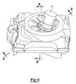
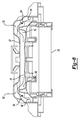
- Figures 8 and 9 show cross-sectional views of the motor mount and the fan assembly taken along lines 8-8 and 9-9 of Figure 6 , respectively.
- the internal walls of the upper panel 32 and the lower panel 30 form a series of chambers that extend radially outwardly from the fan recess and that enable exhaust air to flow from the fan impeller 18 in the fan chamber 20 to the exhaust ports 44a-f, as shown by the arrows in Figures 5 , 8 , and 9 .
- Extending radially outwardly from the fan chamber 20 is a first chamber 50 that forces the air in a vertical direction relative to the fan chamber 20.
- a radially outer chamber 52 which causes the exhaust air to turn 90 degrees to again flow in a radial direction.
- chamber 54 Following the chamber 52 is a chamber 54 that again turns the air by 90 degrees so that it flows in a downward direction. Chamber 54 is followed by a chamber 56 that turn the air by 90 degrees so that the air flows to the exhaust ports 44a-f. By following this tortuous path, the exhaust air loses velocity, which reduces the noise from the exhaust.
- the chambers 50, 52, 54, 56 can have substantially constant or variable widths and heights around their circumference.
- the recess 34 and chambers 50, 52, 54, 56 are canted at an angle of approximately 20 degrees relative to the horizontal. Because of this, the annular wall extends only about 320 degrees around the fan mounting portion. Therefore, there is a blocking portion 60 near the front of the annular wall, which forces the air back toward one of the adjacent corner exhaust ports 44a, 44b.
- the filter assembly 26 is slidably received within the filter housing 28 as illustrated in Figure 2 .
- the insertion direction of the removable filter tray 26 can be disposed at an angle ⁇ 1 which can be between 0 and 45 degrees relative to horizontal.
- the filter housing 28 of the vacuum head 14 may extend downward into the canister 12 at the filter housing's most inward end.
- the angled orientation of the filter tray assembly 26 thus allows the motor 16 and fan impeller 16 to be oriented such that the drive shaft 46 of the motor 16 is disposed at the angle ⁇ 2 relative to vertical, as illustrated in Figure 2 .
- the angel ⁇ 2 can be between 0 and 45 degrees relative to vertical, or if preferred, out of line.
- angles ⁇ 1 and ⁇ 2 can be the same or approximately the same as one another although they can also be varied from one another.
- the angled orientation of the filter tray assembly 26, the electric motor 16, and impeller fan 18 allows the overall stack height of the motor, fan and filter to be reduced in the vertical direction in order to minimize the overall height of the vacuum 10.
Landscapes
- Engineering & Computer Science (AREA)
- Mechanical Engineering (AREA)
- Structures Of Non-Positive Displacement Pumps (AREA)
- Electric Suction Cleaners (AREA)
- Reciprocating Pumps (AREA)
- Blow-Moulding Or Thermoforming Of Plastics Or The Like (AREA)
Abstract
Description
- This application claims the benefit of
U.S. Provisional Application No. 60/979,247, filed on October 11, 2007 - The present disclosure relates to a vacuum exhaust system, and more particularly, to a vacuum having multiple exhaust points.
- The statements in this section merely provide background information related to the present disclosure and may not constitute prior art.
- Vacuums, particularly industrial vacuums, are provided with a vacuum source including a motor and an impeller that draws air into a housing through an inlet port, through a filter and forces the air out through an exhaust port. The air passing through the outlet port can cause high noise levels as well as high velocity of airflow in one direction which can be disruptive to dust and debris near the vacuum.
- This section provides a general summary of the disclosure, and is not a comprehensive disclosure of its full scope or all of its features.
- A vacuum is provided including a housing. A drive motor is disposed in the housing and includes a fan impeller attached to the drive motor and disposed in a fan chamber within the housing. An intake port extends into the housing. An exhaust system is in communication with the fan chamber and includes a plurality of exhaust openings in the housing.
- Where there is a vacuum comprising all of these features, there is provided a first aspect of the present invention for a vacuum which comprise
a housing;
a drive motor disposed in said housing;
a fan chamber disposed in said housing;
a fan impeller attached to said drive motor and disposed in said fan chamber;
an intake port extending into said housing; and
an exhaust system in communication with said fan chamber, said exhaust system including a plurality of exhaust openings in said housing. - According to a second aspect of the present invention, there is provided a vacuum, comprising:
- a housing;
- a drive motor disposed in said housing;
- a fan chamber disposed in said housing;
- a fan impeller attached to said drive motor and disposed in said fan chamber;
- an intake port extending into said housing; and
- an exhaust system in communication with said fan chamber, said exhaust system including a plurality of exhaust openings in said housing;
- wherein said fan chamber is in communication with said plurality of exhaust openings via a radially extending chamber defined between upper and lower panels, said radially extending chamber including at least one vertical section and at least one radially outwardly extending section.
- The plurality of exhaust openings can be disposed on at least two sides of said housing.
- Alternatively the plurality of exhaust openings can be disposed on at least three sides of said housing.
- The upper and lower panels may be canted at an angle of between 0 and 45 degrees from horizontal.
- According to a third aspect of the present invention, there is provided a vacuum, comprising:
- a housing;
- a drive motor disposed in said housing;
- a fan chamber disposed in said housing;
- a fan impeller attached to said drive motor and disposed in said fan chamber;
- an intake port extending into said housing; and
- an exhaust system in communication with said fan chamber, said exhaust system including a plurality of exhaust openings in said housing;
- wherein said fan chamber communicates with a first vertical chamber that forces air in a vertical direction relative to the fan chamber, said first vertical chamber communicates with a first radially outer chamber that forces air to turn radially outward relative to the first vertical chamber, said first radially outer chamber communicates with a second vertical chamber that forces air to turn in a vertical direction relative to said first radially outer chamber, said second vertical chamber communicates with a second radially outer chamber that forces air to turn radially outward relative to the second vertical chamber and communicates with said plurality of exhaust openings in said housing.
- The plurality of exhaust openings can be disposed on at least two sides of said housing.
- Further areas of applicability will become apparent from the description provided herein. The description and specific examples in this summary are intended for purposes of illustration only and are not intended to limit the scope of the present disclosure.
- The drawings described herein are for illustration purposes only and are not intended to limit the scope of the present disclosure in any way.
-
Figure 1 is a perspective view of a shop vacuum incorporating a multi-point exhaust system according to the principles of the present disclosure; -
Figure 2 is a partial cross-sectional view of the vacuum head according to the principles of the present disclosure; -
Figure 3 is a front perspective view of a fan chamber lower panel according to the principles of the present disclosure; -
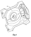
Figure 4 is a bottom perspective view of the lower panel of the fan chamber; -
Figure 5 is a side perspective view of the lower panel; -
Figure 6 is a perspective view of a motor assembly mounted to the upper panel of the fan chamber; -
Figure 7 is an upper perspective view of the upper panel of the fan chamber; -
Figure 8 is a partial cross-sectional view taken along line 8-8 ofFig.6 showing the upper and lower panels of the fan chamber; and -
Figure 9 is a diagonal cross-sectional view taken along line 9-9 ofFig.6 showing the upper and lower panels of the fan chamber. - The following description is merely exemplary in nature and is not intended to limit the present disclosure, application, or uses. It should be understood that throughout the drawings, corresponding reference numerals indicate like or corresponding parts and features.
- Example embodiments are provided so that this disclosure will be thorough, and will fully convey the scope to those who are skilled in the art. Numerous specific details are set forth such as examples of specific components, devices, and methods, to provide a thorough understanding of embodiments of the present disclosure. It will be apparent to those skilled in the art that specific details need not be employed, that example embodiments may be embodied in many different forms and that neither should be construed to limit the scope of the disclosure. In some example embodiments, well-known processes, well-known device structures, and well-known technologies are not described in detail.
- The terminology used herein is for the purpose of describing particular example embodiments only and is not intended to be limiting. As used herein, the singular forms "a", "an" and "the" may be intended to include the plural forms as well, unless the context clearly indicates otherwise. The terms "comprises," "comprising," "including," and "having," are inclusive and therefore specify the presence of stated features, integers, steps, operations, elements, and/or components, but do not preclude the presence or addition of one or more other features, integers, steps, operations, elements, components, and/or groups thereof.
- When an element or layer is referred to as being "on", "engaged to", "connected to" or "coupled to" another element or layer, it may be directly on, engaged, connected or coupled to the other element or layer, or intervening elements or layers may be present. In contrast, when an element is referred to as being "directly on," "directly engaged to", "directly connected to" or "directly coupled to" another element or layer, there may be no intervening elements or layers present. Other words used to describe the relationship between elements should be interpreted in a like fashion (e.g., "between" versus "directly between," "adjacent" versus "directly adjacent," etc.). As used herein, the term "and/or" includes any and all combinations of one or more of the associated listed items.
- Although the terms first, second, third, etc. may be used herein to describe various elements, components, regions, layers and/or sections, these elements, components, regions, layers and/or sections should not be limited by these terms. These terms may be only used to distinguish one element, component, region, layer or section from another region, layer or section. Terms such as "first," "second," and other numerical terms when used herein do not imply a sequence or order unless clearly indicated by the context. Thus, a first element, component, region, layer or section discussed below could be termed a second element, component, region, layer or section without departing from the teachings of the example embodiments.
- Spatially relative terms, such as "inner," "outer," "beneath", "below", "lower", "above", "upper" and the like, may be used herein for ease of description to describe one element or feature's relationship to another element(s) or feature(s) as illustrated in the figures. Spatially relative terms may be intended to encompass different orientations of the device in use or operation in addition to the orientation depicted in the figures. For example, if the device in the figures is turned over, elements described as "below" or "beneath" other elements or features would then be oriented "above" the other elements or features. Thus, the example term "below" can encompass both an orientation of above and below. The device may be otherwise oriented (rotated 90 degrees or at other orientations) and the spatially relative descriptors used herein interpreted accordingly.
- With reference to
Figures 1-3 , anexample vacuum 10 will be described. Thevacuum 10 includes acanister 12 and avacuum head 14 that closes thecanister 12. As shown inFigure 2 , thevacuum head 14 may support adrive motor 16. Thedrive motor 16 may support afan impeller 18, which may be provided in afan chamber 20 of thevacuum head 14. Thefan chamber 20 may be in fluid communication with anintake port 22 and anexhaust system 24. Theintake port 22 may be covered by afilter assembly 26 situated in afilter housing 28 of thevacuum head 14. Thecanister 12 can include asuction inlet 29. - The
motor 16, when powered up, may rotate thefan impeller 18 to draw air through thesuction inlet 29 into thecanister 12, from thecanister 12 through thefilter assembly 26, through theintake port 22 and into thefan chamber 20. Theimpeller fan 18 may push the air in thefan chamber 20 through theexhaust system 24 and out of thevacuum 10. - The
fan chamber 20 can be defined by alower panel 30 and anupper panel 32 which sandwich thefan impeller 18. As shown inFigure 3 , thelower panel 30 of thefan chamber 20 defines a generally centrally locatedrecess 34 defining a lower wall of thefan chamber 20. A centrally locatedaperture 36 defines theair intake port 22 into thefan chamber 20. A series ofperimeter walls 38 define a plurality of channels 40 a-f leading to multiple corresponding exhaust points 42 a-f of theexhaust system 24. Theupper panel 32 engages an upper surface ofwalls 38 to enclose the channels 40 a-f as illustrated inFigure 2 . The exhaust points 42a-f each correspond to anexhaust opening 44a-f provided in circumferentially spaced locations around saidvacuum head 14, as shown inFigure 1 . Theexhaust openings 44a-f can be disposed in the sides and back of thevacuum 10 so that the exhaust air is not directed to the front of thevacuum 10 where dirt and debris that is being picked up can be disturbed. Alternative arrangements of theexhaust openings 44a-f can be provided with theexhaust openings 44a-f on two or more sides of the housing and in the corners or in the centers thereof depending upon desired uses. The multiple exhaust points provide for quieter, lower velocity discharge of the air from the vacuum source. - As can be seen in
Figure 3 , thelower panel 30 can define an access opening for thefilter tray assembly 26 withchannels -
Figures 8 and9 show cross-sectional views of the motor mount and the fan assembly taken along lines 8-8 and 9-9 ofFigure 6 , respectively. When assembled, the internal walls of theupper panel 32 and thelower panel 30 form a series of chambers that extend radially outwardly from the fan recess and that enable exhaust air to flow from thefan impeller 18 in thefan chamber 20 to theexhaust ports 44a-f, as shown by the arrows inFigures 5 ,8 , and9 . Extending radially outwardly from thefan chamber 20 is afirst chamber 50 that forces the air in a vertical direction relative to thefan chamber 20. Next, is a radiallyouter chamber 52 which causes the exhaust air to turn 90 degrees to again flow in a radial direction. Following thechamber 52 is achamber 54 that again turns the air by 90 degrees so that it flows in a downward direction.Chamber 54 is followed by achamber 56 that turn the air by 90 degrees so that the air flows to theexhaust ports 44a-f. By following this tortuous path, the exhaust air loses velocity, which reduces the noise from the exhaust. Thechambers - As shown in the drawings, the
recess 34 andchambers portion 60 near the front of the annular wall, which forces the air back toward one of the adjacentcorner exhaust ports - The
filter assembly 26 is slidably received within thefilter housing 28 as illustrated inFigure 2 . As illustrated inFigure 2 , the insertion direction of theremovable filter tray 26 can be disposed at an angle α1 which can be between 0 and 45 degrees relative to horizontal. Thus, thefilter housing 28 of thevacuum head 14 may extend downward into thecanister 12 at the filter housing's most inward end. The angled orientation of thefilter tray assembly 26 thus allows themotor 16 andfan impeller 16 to be oriented such that the drive shaft 46 of themotor 16 is disposed at the angle α2 relative to vertical, as illustrated inFigure 2 . The angel α2 can be between 0 and 45 degrees relative to vertical, or if preferred, out of line. The angles α1 and α2 can be the same or approximately the same as one another although they can also be varied from one another. The angled orientation of thefilter tray assembly 26, theelectric motor 16, andimpeller fan 18 allows the overall stack height of the motor, fan and filter to be reduced in the vertical direction in order to minimize the overall height of thevacuum 10. - The foregoing description of the embodiments has been provided for purposes of illustration and description. It is not intended to be exhaustive or to limit the invention. Individual elements or features of a particular embodiment are generally not limited to that particular embodiment, but, where applicable, are interchangeable and can be used in a selected embodiment, even if not specifically shown or described. The same may also be varied in many ways. Such variations are not to be regarded as a departure from the invention, and all such modifications are intended to be included within the scope of the invention.
Claims (13)
Applications Claiming Priority (1)
| Application Number | Priority Date | Filing Date | Title |
|---|---|---|---|
| US97924707P | 2007-10-11 | 2007-10-11 |
Publications (3)
| Publication Number | Publication Date |
|---|---|
| EP2047782A2 true EP2047782A2 (en) | 2009-04-15 |
| EP2047782A3 EP2047782A3 (en) | 2012-12-12 |
| EP2047782B1 EP2047782B1 (en) | 2013-12-11 |
Family
ID=40342975
Family Applications (1)
| Application Number | Title | Priority Date | Filing Date |
|---|---|---|---|
| EP20080166383 Not-in-force EP2047782B1 (en) | 2007-10-11 | 2008-10-10 | Vacuum cleaner with mutliple exhaust points |
Country Status (3)
| Country | Link |
|---|---|
| US (1) | US8261406B2 (en) |
| EP (1) | EP2047782B1 (en) |
| CN (1) | CN201337392Y (en) |
Cited By (3)
| Publication number | Priority date | Publication date | Assignee | Title |
|---|---|---|---|---|
| RU2433778C1 (en) * | 2009-06-25 | 2011-11-20 | Кабусики Кайся Тосиба | Dust-collecting device and electric vacuum cleaner |
| EP2696732A4 (en) * | 2011-04-15 | 2015-02-25 | Martins Maintenance Inc | ASPIRATOR AND SUCTION SYSTEM AND METHODS OF USING IN A HIGH-FLOOR FLOOR ENVIRONMENT |
| EP3238592A1 (en) * | 2016-04-27 | 2017-11-01 | Diversey Switzerland Services GmbH | Vacuum cleaner |
Families Citing this family (12)
| Publication number | Priority date | Publication date | Assignee | Title |
|---|---|---|---|---|
| US20090204622A1 (en) * | 2008-02-11 | 2009-08-13 | Novell, Inc. | Visual and non-visual cues for conveying state of information cards, electronic wallets, and keyrings |
| US20090077655A1 (en) * | 2007-09-19 | 2009-03-19 | Novell, Inc. | Processing html extensions to enable support of information cards by a relying party |
| US20090228885A1 (en) * | 2008-03-07 | 2009-09-10 | Novell, Inc. | System and method for using workflows with information cards |
| US8087060B2 (en) * | 2007-03-16 | 2011-12-27 | James Mark Norman | Chaining information card selectors |
| US20090204542A1 (en) * | 2008-02-11 | 2009-08-13 | Novell, Inc. | Privately sharing relying party reputation with information card selectors |
| US8561172B2 (en) * | 2008-08-29 | 2013-10-15 | Novell Intellectual Property Holdings, Inc. | System and method for virtual information cards |
| US20130220426A1 (en) * | 2012-02-28 | 2013-08-29 | Emerson Electric Co. | Method, Apparatus, and System for Controlling the Exhaust of a Vacuum Device |
| JP2018064849A (en) * | 2016-10-21 | 2018-04-26 | 日本電産株式会社 | Motor module and cleaner |
| USD877435S1 (en) * | 2018-05-08 | 2020-03-03 | Shop Vac Corporation | Vacuum cleaner |
| DE102019105086A1 (en) * | 2019-02-28 | 2020-09-03 | Alfred Kärcher SE & Co. KG | Suction device with duct piece |
| USD933317S1 (en) * | 2019-03-07 | 2021-10-12 | Black & Decker Inc. | Vacuum |
| DE102024113320A1 (en) * | 2024-05-13 | 2025-11-13 | Alfred Kärcher SE & Co. KG | VACUUM CLEANER SYSTEM |
Family Cites Families (8)
| Publication number | Priority date | Publication date | Assignee | Title |
|---|---|---|---|---|
| US4533370A (en) * | 1982-03-30 | 1985-08-06 | Sharp Kabushiki Kaisha | Electric cleaner with minimum noise |
| JPH03272721A (en) * | 1990-03-20 | 1991-12-04 | Matsushita Electric Ind Co Ltd | vacuum cleaner |
| US5289612A (en) * | 1992-08-13 | 1994-03-01 | Ryobi Motor Products Corporation | Noise reduction system for hard body vacuum |
| US5513417A (en) * | 1993-07-19 | 1996-05-07 | Samsung Electronics Co., Ltd. | Silencing device for vacuum cleaner |
| US6219880B1 (en) * | 1998-09-17 | 2001-04-24 | Pullman-Holt Corporation | Vacuum cleaner |
| DE102004013065A1 (en) * | 2004-03-12 | 2005-09-29 | Alfred Kärcher Gmbh & Co. Kg | Vacuum cleaner has inlet and dust collector and two alternative air outlets governed by a control unit |
| GB2423037A (en) * | 2005-02-15 | 2006-08-16 | Techtronic Ind Co Ltd | Cyclonic separator for suction cleaner |
| US7627928B2 (en) * | 2005-02-17 | 2009-12-08 | Shop-Vac Corporation | Removable internal air diffuser |
-
2008
- 2008-10-07 US US12/246,521 patent/US8261406B2/en not_active Expired - Fee Related
- 2008-10-10 EP EP20080166383 patent/EP2047782B1/en not_active Not-in-force
- 2008-10-13 CN CNU2008201798678U patent/CN201337392Y/en not_active Expired - Fee Related
Cited By (12)
| Publication number | Priority date | Publication date | Assignee | Title |
|---|---|---|---|---|
| RU2433778C1 (en) * | 2009-06-25 | 2011-11-20 | Кабусики Кайся Тосиба | Dust-collecting device and electric vacuum cleaner |
| EP2696732A4 (en) * | 2011-04-15 | 2015-02-25 | Martins Maintenance Inc | ASPIRATOR AND SUCTION SYSTEM AND METHODS OF USING IN A HIGH-FLOOR FLOOR ENVIRONMENT |
| US9119512B2 (en) | 2011-04-15 | 2015-09-01 | Martins Maintenance, Inc. | Vacuum cleaner and vacuum cleaning system and methods of use in a raised floor environment |
| US9888820B2 (en) | 2011-04-15 | 2018-02-13 | Martins Maintenance, Inc. | Vacuum cleaner and vacuum cleaning system and methods of use in a raised floor environment |
| EP3238592A1 (en) * | 2016-04-27 | 2017-11-01 | Diversey Switzerland Services GmbH | Vacuum cleaner |
| WO2017186823A1 (en) | 2016-04-27 | 2017-11-02 | Diversey Switzerland Services Gmbh | Vacuum cleaner |
| CN109068909A (en) * | 2016-04-27 | 2018-12-21 | 戴弗西公司 | Vacuum cleaner |
| AU2017256737B2 (en) * | 2016-04-27 | 2019-05-16 | Diversey, Inc. | Vacuum cleaner |
| CN109068909B (en) * | 2016-04-27 | 2021-08-24 | 戴弗西公司 | vacuum cleaner |
| US11116369B2 (en) | 2016-04-27 | 2021-09-14 | Diversey, Inc. | Vacuum cleaner |
| US11452412B2 (en) | 2016-04-27 | 2022-09-27 | Diversey, Inc. | Vacuum cleaner |
| US11937759B2 (en) | 2016-04-27 | 2024-03-26 | Diversey Switzerland Services Gmbh | Vacuum cleaner |
Also Published As
| Publication number | Publication date |
|---|---|
| US8261406B2 (en) | 2012-09-11 |
| EP2047782B1 (en) | 2013-12-11 |
| EP2047782A3 (en) | 2012-12-12 |
| CN201337392Y (en) | 2009-11-04 |
| US20090095360A1 (en) | 2009-04-16 |
Similar Documents
| Publication | Publication Date | Title |
|---|---|---|
| EP2047782B1 (en) | Vacuum cleaner with mutliple exhaust points | |
| US20250196041A1 (en) | Air cleaner | |
| EP2993419B1 (en) | Air cleaner | |
| EP1929914B1 (en) | Fan motor case assembly for noise reduction | |
| US9677571B2 (en) | Device for the passage of air | |
| US9914082B2 (en) | Air cleaner | |
| KR20230007291A (en) | Air cleaning apparatus | |
| US8667638B2 (en) | Robot cleaner | |
| KR102887228B1 (en) | Air circulator and air cleaner including air circulator | |
| KR102829014B1 (en) | Diffuser, diffuser assembly, and air conditioner having the same | |
| EP1929915A2 (en) | Fan motor case | |
| EP2535594A1 (en) | Centrifugal blower | |
| US20060059873A1 (en) | Blower Having a Carrying Frame | |
| KR20210099381A (en) | Portable air caring device | |
| EP2255898B1 (en) | Fume suction unit | |
| CN116018482A (en) | air purifier | |
| KR20210110932A (en) | Portable air caring device | |
| KR20210094910A (en) | Portable air caring device and provided therein | |
| EP1952742A2 (en) | Motor assembly and vacuum cleaner having the same | |
| WO2000047099A1 (en) | A vaneless impeller housing for a vacuum cleaner | |
| US20240382054A1 (en) | Noise reduction device for cleaners | |
| US20240382053A1 (en) | Noise reduction device for cleaners | |
| EP4517201A1 (en) | Exhaust device | |
| KR102779738B1 (en) | Assembly for venting air and air purifier comprising same | |
| KR200451529Y1 (en) | Air cleaner |
Legal Events
| Date | Code | Title | Description |
|---|---|---|---|
| PUAI | Public reference made under article 153(3) epc to a published international application that has entered the european phase |
Free format text: ORIGINAL CODE: 0009012 |
|
| AK | Designated contracting states |
Kind code of ref document: A2 Designated state(s): AT BE BG CH CY CZ DE DK EE ES FI FR GB GR HR HU IE IS IT LI LT LU LV MC MT NL NO PL PT RO SE SI SK TR |
|
| AX | Request for extension of the european patent |
Extension state: AL BA MK RS |
|
| PUAL | Search report despatched |
Free format text: ORIGINAL CODE: 0009013 |
|
| AK | Designated contracting states |
Kind code of ref document: A3 Designated state(s): AT BE BG CH CY CZ DE DK EE ES FI FR GB GR HR HU IE IS IT LI LT LU LV MC MT NL NO PL PT RO SE SI SK TR |
|
| AX | Request for extension of the european patent |
Extension state: AL BA MK RS |
|
| RIC1 | Information provided on ipc code assigned before grant |
Ipc: A47L 9/22 20060101ALI20121107BHEP Ipc: A47L 9/00 20060101ALI20121107BHEP Ipc: A47L 5/36 20060101AFI20121107BHEP |
|
| 17P | Request for examination filed |
Effective date: 20130227 |
|
| GRAJ | Information related to disapproval of communication of intention to grant by the applicant or resumption of examination proceedings by the epo deleted |
Free format text: ORIGINAL CODE: EPIDOSDIGR1 |
|
| GRAP | Despatch of communication of intention to grant a patent |
Free format text: ORIGINAL CODE: EPIDOSNIGR1 |
|
| GRAP | Despatch of communication of intention to grant a patent |
Free format text: ORIGINAL CODE: EPIDOSNIGR1 |
|
| AKX | Designation fees paid |
Designated state(s): DE GB |
|
| INTG | Intention to grant announced |
Effective date: 20130802 |
|
| GRAS | Grant fee paid |
Free format text: ORIGINAL CODE: EPIDOSNIGR3 |
|
| GRAA | (expected) grant |
Free format text: ORIGINAL CODE: 0009210 |
|
| AK | Designated contracting states |
Kind code of ref document: B1 Designated state(s): DE GB |
|
| REG | Reference to a national code |
Ref country code: GB Ref legal event code: FG4D |
|
| REG | Reference to a national code |
Ref country code: DE Ref legal event code: R096 Ref document number: 602008029201 Country of ref document: DE Effective date: 20140206 |
|
| REG | Reference to a national code |
Ref country code: DE Ref legal event code: R097 Ref document number: 602008029201 Country of ref document: DE |
|
| PLBE | No opposition filed within time limit |
Free format text: ORIGINAL CODE: 0009261 |
|
| STAA | Information on the status of an ep patent application or granted ep patent |
Free format text: STATUS: NO OPPOSITION FILED WITHIN TIME LIMIT |
|
| 26N | No opposition filed |
Effective date: 20140912 |
|
| REG | Reference to a national code |
Ref country code: DE Ref legal event code: R097 Ref document number: 602008029201 Country of ref document: DE Effective date: 20140912 |
|
| PGFP | Annual fee paid to national office [announced via postgrant information from national office to epo] |
Ref country code: GB Payment date: 20191010 Year of fee payment: 12 |
|
| GBPC | Gb: european patent ceased through non-payment of renewal fee |
Effective date: 20201010 |
|
| PG25 | Lapsed in a contracting state [announced via postgrant information from national office to epo] |
Ref country code: GB Free format text: LAPSE BECAUSE OF NON-PAYMENT OF DUE FEES Effective date: 20201010 |
|
| PGFP | Annual fee paid to national office [announced via postgrant information from national office to epo] |
Ref country code: DE Payment date: 20210831 Year of fee payment: 14 |
|
| REG | Reference to a national code |
Ref country code: DE Ref legal event code: R119 Ref document number: 602008029201 Country of ref document: DE |
|
| PG25 | Lapsed in a contracting state [announced via postgrant information from national office to epo] |
Ref country code: DE Free format text: LAPSE BECAUSE OF NON-PAYMENT OF DUE FEES Effective date: 20230503 |