EP2047351B1 - Load handling vehicle - Google Patents
Load handling vehicle Download PDFInfo
- Publication number
- EP2047351B1 EP2047351B1 EP07748326A EP07748326A EP2047351B1 EP 2047351 B1 EP2047351 B1 EP 2047351B1 EP 07748326 A EP07748326 A EP 07748326A EP 07748326 A EP07748326 A EP 07748326A EP 2047351 B1 EP2047351 B1 EP 2047351B1
- Authority
- EP
- European Patent Office
- Prior art keywords
- pedal
- floor portion
- console
- sensor
- plane
- Prior art date
- Legal status (The legal status is an assumption and is not a legal conclusion. Google has not performed a legal analysis and makes no representation as to the accuracy of the status listed.)
- Active
Links
- 230000001747 exhibiting effect Effects 0.000 claims abstract description 4
- XEEYBQQBJWHFJM-UHFFFAOYSA-N Iron Chemical compound [Fe] XEEYBQQBJWHFJM-UHFFFAOYSA-N 0.000 description 2
- 230000000994 depressogenic effect Effects 0.000 description 2
- 238000005065 mining Methods 0.000 description 2
- 230000003213 activating effect Effects 0.000 description 1
- 229910052742 iron Inorganic materials 0.000 description 1
- 239000002184 metal Substances 0.000 description 1
- 229910052751 metal Inorganic materials 0.000 description 1
- 230000001105 regulatory effect Effects 0.000 description 1
Images
Classifications
-
- B—PERFORMING OPERATIONS; TRANSPORTING
- B60—VEHICLES IN GENERAL
- B60K—ARRANGEMENT OR MOUNTING OF PROPULSION UNITS OR OF TRANSMISSIONS IN VEHICLES; ARRANGEMENT OR MOUNTING OF PLURAL DIVERSE PRIME-MOVERS IN VEHICLES; AUXILIARY DRIVES FOR VEHICLES; INSTRUMENTATION OR DASHBOARDS FOR VEHICLES; ARRANGEMENTS IN CONNECTION WITH COOLING, AIR INTAKE, GAS EXHAUST OR FUEL SUPPLY OF PROPULSION UNITS IN VEHICLES
- B60K26/00—Arrangements or mounting of propulsion unit control devices in vehicles
- B60K26/02—Arrangements or mounting of propulsion unit control devices in vehicles of initiating means or elements
- B60K26/021—Arrangements or mounting of propulsion unit control devices in vehicles of initiating means or elements with means for providing feel, e.g. by changing pedal force characteristics
-
- B—PERFORMING OPERATIONS; TRANSPORTING
- B60—VEHICLES IN GENERAL
- B60T—VEHICLE BRAKE CONTROL SYSTEMS OR PARTS THEREOF; BRAKE CONTROL SYSTEMS OR PARTS THEREOF, IN GENERAL; ARRANGEMENT OF BRAKING ELEMENTS ON VEHICLES IN GENERAL; PORTABLE DEVICES FOR PREVENTING UNWANTED MOVEMENT OF VEHICLES; VEHICLE MODIFICATIONS TO FACILITATE COOLING OF BRAKES
- B60T7/00—Brake-action initiating means
- B60T7/02—Brake-action initiating means for personal initiation
- B60T7/04—Brake-action initiating means for personal initiation foot actuated
- B60T7/06—Disposition of pedal
-
- G—PHYSICS
- G05—CONTROLLING; REGULATING
- G05G—CONTROL DEVICES OR SYSTEMS INSOFAR AS CHARACTERISED BY MECHANICAL FEATURES ONLY
- G05G1/00—Controlling members, e.g. knobs or handles; Assemblies or arrangements thereof; Indicating position of controlling members
- G05G1/30—Controlling members actuated by foot
- G05G1/36—Mounting units comprising an assembly of two or more pedals, e.g. for facilitating mounting
Definitions
- This invention relates to a load handling vehicle exhibiting an operator's compartment, which comprises a floor portion and a pedal assembly, said pedal assembly comprising a pedal.
- the invention relates to a truck having a lifting assembly, for example a forklift truck, which exhibits an operator's compartment, wherein the central part of the floor portion of the operator's compartment, including the operator's seat, steering gear, controls and pedal assembly, can be turned 0-180 degrees in order to enable forward-facing or sideways-facing driving of the vehicle both forward and backwards.
- sideways-facing driving means that the body of the operator is facing in a direction deviating from the driving direction during the driving. Since the pedals follow the turning movement of such an operator's compartment, the pedal assembly has to be compact and centrally mounted. Furthermore, it is desirable that the positions of the pedals should be adjustable to fit different operators.
- a relatively compact pedal assembly is described in US 4 060 144 , which reveals all the features of the preamble of claim 1, which discloses a brake and throttle control assembly for a mining vehicle.
- the assembly exhibits two coaxial shafts, which are supported in bearings on two supports being welded to the cab floor.
- An accelerator pedal is attached to one shaft and a brake pedal to the other shaft. When operating the accelerator pedal, one shaft is caused to rotate, and when operating the brake pedal, the other shaft is caused to rotate.
- An angular sensor is arranged at the end of the respective shaft in order to measure throttle position and brake position.
- the assembly according to US 4 060 144 exhibits a number of problems. Even if the assembly is compact in the depth direction, it exhibits a relatively large extension in the lateral direction because of the angular sensors, for which there is normally no space in a load handling vehicle having a turning operator's compartment. Furthermore, the assembly according to US 4 060 144 lacks adjustment possibilities for operator adapted adjustment of the pedal positions.
- the object of the present invention is to produce a load handling vehicle with a driver's compartment exhibiting a compact pedal assembly, said pedal assembly being adjustable in order to enable adjustment of the pedal positions.
- the vehicle according to the invention is characterized in that the pedal assembly comprises a console on which said pedal is arranged, said console extending through an opening in the floor portion so that the console comprises an upper portion, which is arranged above the plane of the floor portion, and a lower portion, which is arranged below the plane of the floor portion, said console being tiltably arranged at the floor portion about a pivot shaft, which is parallel to the plane of the floor portion.
- the pedal assembly according to the invention is compact and also individually adjustable.
- the floor portion can be designed with a radius being smaller than the extension of the pedals, something which is a great advantage, particularly in turning operator's compartments.
- the extension of the console below the floor portion enables sensors for detecting the pedal movements, for example the sensor for the brake pedal movement, to be placed below the floor portion, which allows a narrow pedal assembly.
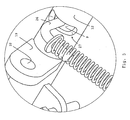
- FIG. 1 shows a portion of the operator's compartment of a load handling vehicle, in this case a forklift truck, according to one embodiment of the invention.
- the operator's compartment comprises a pedal assembly 1, which is mounted in a circular floor portion 2.
- the floor portion 2 also other equipment (not shown) for driving the forklift truck is mounted, such as an operator's seat, steering gear and controls for the loading devices of the forklift truck.
- the floor portion 2, including the pedal assembly 1 can be turned 180 degrees in order to enable forward-facing driving of the forklift truck both in a forward driving direction and in a backward driving direction.
- the pedal assembly 1 comprises a console 3 in the form of a cut out and bent metal sheet.
- the console 3 has a first, upper portion 4, which is planar and T-shaped, and a second, lower portion 5, which is U-shaped (se Figure 2 and 4 ).
- the upper portion 4 exhibits a rectangular first, upper part 6, extending in the cross-direction of the console 3, and a rectangular second, lower part 7, extending in the longitudinal direction of the console 3 and connecting orthogonally to the central portion of the upper part 6.
- the console 3 is mounted in an opening in the floor portion 2 so that the upper portion 4 projects above the plane of the floor portion 2 and the lower portion 5 is located below the plane of the floor portion 2. Accordingly, the longitudinal direction of the console 3 forms an angle with the plane of the floor portion 2, and the longitudinal direction of the console 3, when being projected onto the plane of the floor portion 2, has a substantially radial alignment.
- the opening which is concealed by a cover plate 38 in the figures, is arranged at the rim 39 of the floor portion 2 so that the upper portion 4 of the console 3 extends out past the rim 39.
- a homogenous first, inner shaft 9 is rotatably mounted in two shaft supports 10, 11, projecting from the top side 8 (see Figure 3 ).
- a tubular second, outer shaft 12 is arranged, said outer shaft 12 also being rotatably mounted in the shaft supports 10 and 11.
- the outer shaft 12 has an internal diameter which is somewhat larger than the diameter of the inner shaft 9, so that the outer shaft 12 is substantially frictionlessly and rotatably arranged onto and coaxially to the inner shaft 9.
- a brake pedal arm 13, 14 is rigidly connected to the envelope surface of the outer shaft 12, so that the brake pedal arms 13, 14 are projecting from the outer shaft 12 substantially in parallel with each other in a direction obliquely downwards towards the centre of the floor portion 2.
- a brake pedal 15, 16 is pivotally mounted in a pivot shaft 17, 18 (see Figure 4 ), which is substantially parallel to the outer shaft 12.
- a link lug 19 rigidly mounted on the envelope surface of the outer shaft 12 .
- the lug 19 projects from the central portion of the shaft 12 and exhibits a through hole 32 (see Figure 5 ) for articulated cooperation with a forked link 20, which actuates a hydraulic valve 22 via an adjustable push rod 21.
- the hydraulic valve 22 is mounted in the console 3, more specifically in the rear part of the U-shaped lower portion 5 of the console 3, i.e. below the plane of the floor portion 2.
- a gas pedal arm 23 is rigidly connected to the right-hand end of the inner shaft 9, so that the gas pedal arm 23 forms an angle with the longitudinal direction of the shaft 9 which is somewhat smaller than 90 degrees.
- the gas pedal arm 23 projects in a direction obliquely downwards towards the centre of the floor portion 2.
- a gas pedal 24 is pivotally mounted in a pivot shaft 25 (see Figure 4 ).
- a sensor pin 26, in the form of an angled round iron, is rigidly mounted on the inner shaft.
- the sensor pin 26 projects from the inner shaft 9 through an opening 27 in the outer shaft 12, to the side of the lug 19 (see Figure 5 ).
- the opening 27 has an extension which allows the shafts 9, 12 to be rotated independently of each other within a predetermined angular range.
- the operator of the forklift truck depresses one or both of the brake pedals 15, 16, wherein the resulting braking movement is transformed into a rotary movement of the outer shaft 12.
- the rotary movement is detected by the hydraulic valve 22 via the lug 19, the forked link 20 and the push rod 21.
- the hydraulic valve 22 will then provide for the generation of a braking torque for the forklift truck, for example by means of activating the travel brakes of the forklift truck as function of detected brake position. Owing to the opening 27, the braking movement does not influence the sensor pin 26 and the inner shaft 9.
- a first pressure spring 28 is arranged for returning the brake pedals 15, 16 to an adjustable initial position when they are not depressed, said initial position thus constituting an upper end position for the brake pedals 15, 16.
- a second lug 33 having an adjusting screw 29, is arranged on the outer shaft 12. The adjusting screw 29 is set so that it is brought to cooperate with the console 3 at the upper end position of the brake pedals 15, 16. Accordingly, the position of the adjusting screw 29 defines the upper end position.
- the operator depresses the accelerator pedal 24, wherein the resulting throttle opening movement is transformed into a rotary movement of the inner shaft 9. Owing to the opening 27, the throttle opening movement does not influence the lug 19 and the outer shaft 12.
- the throttle opening movement is detected by a sensor (not shown) which, in a known way, is arranged to read the position of the sensor pin 26.
- a second pressure spring 30 is arranged for returning the accelerator pedal 24 to an adjustable initial position when it is not depressed, said initial position thus constituting an upper end position for the accelerator pedal 24.
- the pedal assembly preferably comprises a stop (not shown) for the inner shaft 9, said stop defining the upper end position.
- the sensor is mounted on a sensor attachment 31, which is rigidly connected to the console 3 in connection with the projecting sensor pin 26.
- the sensor can be mechanically connected to the sensor pin 26, but is preferably some type of contactless sensor.
- the sensor provides for the generation of a driving torque for the forklift truck as a function of detected throttle position.
- the console 3 supports brake and accelerator pedals with associated sensors for detecting the movements of the brake and accelerator pedals, wherein the hydraulic valve for detecting the braking movement is arranged below the plane of the floor portion and wherein the sensor for the throttle opening movement is arranged above the plane of the floor portion.
- the pedal assembly can also comprise a second sensor (not shown) for the braking movement, said second sensor being arranged on the console above the plane of the floor portion.
- a second sensor which can be contactless, can be used in order to supply a control and regulating system of the forklift truck with direct information about the braking movement.
- the console 3 is adjustably connected to the floor portion 2 by means of an attachment means 34 in the form of a shaft, which is rigidly connected to the console 3 between the upper portion 4 and the lower portion 5 of the console 3.
- the shaft 34 is arranged to cooperate with shaft attachments 35 in the floor portion 2 in order to constitute a pivot shaft 36, in the plane of the floor portion 2 or in a plane being parallel to the plane of the floor portion 2, for the pedal assembly 1 (see Figure 2 ).
- the shaft attachments 35 are arranged at the bottom side of the floor portion 2, but it is appreciated that they alternatively can be arranged at the top side of the floor portion 2 or in the plane of the floor portion 2.
- the angle of the console 3 in relation to the floor portion 2, and thereby the positions of the pedals 15, 16 and 24 in the height direction, can be adjusted into the desired position by means of tilting the console 3 about the pivot shaft 36.
- the pivot shaft 36 is orthogonal to the longitudinal direction of the console 3 and, accordingly, the pivot shaft 36 is also orthogonal to the longitudinal direction of the operator's compartment irrespective of if the operator's compartment is set for driving forward or backward.
- the pedal assembly 1 comprises a locking means (not shown) for locking the console 3 in the desired position. Accordingly, the pedal assembly 1 is adjustably and lockably arranged in the floor portion 2 in order to enable an individual and ergonomical setting of the pedals 15, 16 and 24 in relation to the floor portion 2.
- the adjustment of the console 3 into the desired position can be done purely manually, e.g. by means of a manually actuated adjusting screw 37.
- the pedal assembly 1 comprises an electric motor (not shown), by means of which the operator can set and lock the console 3 in the desired position in a more automated way.
- electric motors with associated control circuits are known per se, and will not be described more closely here.
- the pedal assembly can comprise two adjacently disposed partial shafts, each being actuated by a pedal of its own and each having its own sensor, wherein the pedal of one partial shaft can be actuated independently of the pedal of the other partial shaft and wherein the movements of the pedals of the partial shafts can be detected separately.
- the inner shaft can be divided into two partial shafts, each having an accelerator pedal of its own, wherein one accelerator pedal is for the forward driving direction and the other is for the backward driving direction.
- a single brake pedal can.be arranged at the outer shaft.
- the single brake pedal can for example be arranged between the two accelerator pedals, wherein the operator uses one accelerator pedal for generating a driving torque in the forward driving direction, the other accelerator pedal for generating a driving torque in the backward driving direction, and the brake pedal for generating a braking torque.
- the invention in the foregoing has been described starting from a load handling vehicle where the floor portion and the pedal assembly can be turned 180 degrees in relation to the longitudinal axis of the vehicle in order to enable forward-facing driving of the vehicle in a forward driving direction and in a backward driving direction
- the invention also is applicable to load handling vehicles where the floor portion and the pedal assembly can be turned into an optional angle within the interval 0-180 degrees in order to enable forward-facing or sideways-facing driving of the vehicle in the forward driving direction and the backward driving direction.
- the operator's compartment can be set such that the longitudinal direction of the operator's compartment and the longitudinal direction of the vehicle do not coincide, something which might be preferable in certain driving situations.
- the invention is applicable in a load handling vehicle where the floor portion and the pedal assembly both are fixed, i.e. not able to turn, in relation to the longitudinal axis of the vehicle.
- the pedal assembly per se can be provided with additional adjustment possibilities.
- the upper part 6 of the upper portion 4 of the console 3 can for example be pivotally and lockably connected to the lower part 7, whereby the desired angle between the parts 6 and 7 can be set.
Abstract
Description
- This invention relates to a load handling vehicle exhibiting an operator's compartment, which comprises a floor portion and a pedal assembly, said pedal assembly comprising a pedal.
- In particular, the invention relates to a truck having a lifting assembly, for example a forklift truck, which exhibits an operator's compartment, wherein the central part of the floor portion of the operator's compartment, including the operator's seat, steering gear, controls and pedal assembly, can be turned 0-180 degrees in order to enable forward-facing or sideways-facing driving of the vehicle both forward and backwards. In this context, sideways-facing driving means that the body of the operator is facing in a direction deviating from the driving direction during the driving. Since the pedals follow the turning movement of such an operator's compartment, the pedal assembly has to be compact and centrally mounted. Furthermore, it is desirable that the positions of the pedals should be adjustable to fit different operators.
- A vehicle of the type mentioned by way of introduction is described in
US 2 384 890 . However, the pedal assembly of this vehicle is relatively bulky and, in addition, adjustment possibilities for an ergonomic setting of the pedal positions are missing. - A relatively compact pedal assembly is described in
US 4 060 144 , which reveals all the features of the preamble ofclaim 1, which discloses a brake and throttle control assembly for a mining vehicle. As is the case in load handling vehicles having a turning operator's compartment, the space which is available for the pedal assembly is limited in mining vehicles. The assembly exhibits two coaxial shafts, which are supported in bearings on two supports being welded to the cab floor. An accelerator pedal is attached to one shaft and a brake pedal to the other shaft. When operating the accelerator pedal, one shaft is caused to rotate, and when operating the brake pedal, the other shaft is caused to rotate. An angular sensor is arranged at the end of the respective shaft in order to measure throttle position and brake position. However, the assembly according toUS 4 060 144 exhibits a number of problems. Even if the assembly is compact in the depth direction, it exhibits a relatively large extension in the lateral direction because of the angular sensors, for which there is normally no space in a load handling vehicle having a turning operator's compartment. Furthermore, the assembly according toUS 4 060 144 lacks adjustment possibilities for operator adapted adjustment of the pedal positions. - The object of the present invention is to produce a load handling vehicle with a driver's compartment exhibiting a compact pedal assembly, said pedal assembly being adjustable in order to enable adjustment of the pedal positions.
- The vehicle according to the invention is characterized in that the pedal assembly comprises a console on which said pedal is arranged, said console extending through an opening in the floor portion so that the console comprises an upper portion, which is arranged above the plane of the floor portion, and a lower portion, which is arranged below the plane of the floor portion, said console being tiltably arranged at the floor portion about a pivot shaft, which is parallel to the plane of the floor portion.
- Owing to the pivot supported console, the pedal assembly according to the invention is compact and also individually adjustable. By means of the central attachment of the console and the central positioning of the brake valve, the floor portion can be designed with a radius being smaller than the extension of the pedals, something which is a great advantage, particularly in turning operator's compartments. Furthermore, the extension of the console below the floor portion enables sensors for detecting the pedal movements, for example the sensor for the brake pedal movement, to be placed below the floor portion, which allows a narrow pedal assembly.
- In the following, the invention will be described more closely with reference to the attached drawings.
-
Figure 1 shows a pedal assembly according to one embodiment of the invention. -
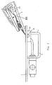
Figure 2 shows the pedal assembly ofFigure 1 from the side. -
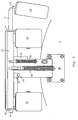
Figure 3 shows the pedal assembly ofFigure 1 from above. -
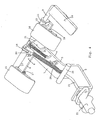
Figure 4 shows the pedal assembly ofFigure 1 in a view where the floor portion has been removed. -
Figure 5 shows a detailed view of a portion of the pedal assembly ofFigure 1 . - In the figures, similar reference numerals refer to similar parts.
-
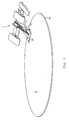
Figure 1 shows a portion of the operator's compartment of a load handling vehicle, in this case a forklift truck, according to one embodiment of the invention. The operator's compartment comprises apedal assembly 1, which is mounted in acircular floor portion 2. In thefloor portion 2, also other equipment (not shown) for driving the forklift truck is mounted, such as an operator's seat, steering gear and controls for the loading devices of the forklift truck. In the forklift truck, thefloor portion 2, including thepedal assembly 1, can be turned 180 degrees in order to enable forward-facing driving of the forklift truck both in a forward driving direction and in a backward driving direction. - The
pedal assembly 1 comprises aconsole 3 in the form of a cut out and bent metal sheet. In the longitudinal direction, theconsole 3 has a first, upper portion 4, which is planar and T-shaped, and a second,lower portion 5, which is U-shaped (seFigure 2 and4 ). The upper portion 4 exhibits a rectangular first,upper part 6, extending in the cross-direction of theconsole 3, and a rectangular second,lower part 7, extending in the longitudinal direction of theconsole 3 and connecting orthogonally to the central portion of theupper part 6. - The
console 3 is mounted in an opening in thefloor portion 2 so that the upper portion 4 projects above the plane of thefloor portion 2 and thelower portion 5 is located below the plane of thefloor portion 2. Accordingly, the longitudinal direction of theconsole 3 forms an angle with the plane of thefloor portion 2, and the longitudinal direction of theconsole 3, when being projected onto the plane of thefloor portion 2, has a substantially radial alignment. The opening, which is concealed by acover plate 38 in the figures, is arranged at therim 39 of thefloor portion 2 so that the upper portion 4 of theconsole 3 extends out past therim 39. - On the top side 8 of the
upper part 6, a homogenous first,inner shaft 9 is rotatably mounted in two shaft supports 10, 11, projecting from the top side 8 (seeFigure 3 ). On theinner shaft 9, and between the shaft supports 10, 11, a tubular second,outer shaft 12 is arranged, saidouter shaft 12 also being rotatably mounted in the shaft supports 10 and 11. Theouter shaft 12 has an internal diameter which is somewhat larger than the diameter of theinner shaft 9, so that theouter shaft 12 is substantially frictionlessly and rotatably arranged onto and coaxially to theinner shaft 9. - At each shaft end of the
outer shaft 12, abrake pedal arm outer shaft 12, so that thebrake pedal arms outer shaft 12 substantially in parallel with each other in a direction obliquely downwards towards the centre of thefloor portion 2. On eachbrake pedal arm brake pedal pivot shaft 17, 18 (seeFigure 4 ), which is substantially parallel to theouter shaft 12. On the envelope surface of theouter shaft 12 is also alink lug 19 rigidly mounted. Thelug 19 projects from the central portion of theshaft 12 and exhibits a through hole 32 (seeFigure 5 ) for articulated cooperation with a forkedlink 20, which actuates ahydraulic valve 22 via anadjustable push rod 21. Thehydraulic valve 22 is mounted in theconsole 3, more specifically in the rear part of the U-shapedlower portion 5 of theconsole 3, i.e. below the plane of thefloor portion 2. - A
gas pedal arm 23 is rigidly connected to the right-hand end of theinner shaft 9, so that thegas pedal arm 23 forms an angle with the longitudinal direction of theshaft 9 which is somewhat smaller than 90 degrees. Thegas pedal arm 23 projects in a direction obliquely downwards towards the centre of thefloor portion 2. On thegas pedal arm 23, agas pedal 24 is pivotally mounted in a pivot shaft 25 (seeFigure 4 ). Asensor pin 26, in the form of an angled round iron, is rigidly mounted on the inner shaft. Thesensor pin 26 projects from theinner shaft 9 through an opening 27 in theouter shaft 12, to the side of the lug 19 (seeFigure 5 ). In the circumferential direction of theshafts opening 27 has an extension which allows theshafts - In order to brake the forklift truck, the operator of the forklift truck depresses one or both of the
brake pedals outer shaft 12. The rotary movement is detected by thehydraulic valve 22 via thelug 19, the forkedlink 20 and thepush rod 21. In a known way, thehydraulic valve 22 will then provide for the generation of a braking torque for the forklift truck, for example by means of activating the travel brakes of the forklift truck as function of detected brake position. Owing to the opening 27, the braking movement does not influence thesensor pin 26 and theinner shaft 9. Afirst pressure spring 28 is arranged for returning thebrake pedals brake pedals second lug 33, having an adjustingscrew 29, is arranged on theouter shaft 12. The adjustingscrew 29 is set so that it is brought to cooperate with theconsole 3 at the upper end position of thebrake pedals screw 29 defines the upper end position. - In order to generate an increased throttle opening, the operator depresses the
accelerator pedal 24, wherein the resulting throttle opening movement is transformed into a rotary movement of theinner shaft 9. Owing to the opening 27, the throttle opening movement does not influence thelug 19 and theouter shaft 12. The throttle opening movement is detected by a sensor (not shown) which, in a known way, is arranged to read the position of thesensor pin 26. Asecond pressure spring 30 is arranged for returning theaccelerator pedal 24 to an adjustable initial position when it is not depressed, said initial position thus constituting an upper end position for theaccelerator pedal 24. The pedal assembly preferably comprises a stop (not shown) for theinner shaft 9, said stop defining the upper end position. The sensor is mounted on asensor attachment 31, which is rigidly connected to theconsole 3 in connection with the projectingsensor pin 26. The sensor can be mechanically connected to thesensor pin 26, but is preferably some type of contactless sensor. The sensor provides for the generation of a driving torque for the forklift truck as a function of detected throttle position. - Accordingly, the
console 3 supports brake and accelerator pedals with associated sensors for detecting the movements of the brake and accelerator pedals, wherein the hydraulic valve for detecting the braking movement is arranged below the plane of the floor portion and wherein the sensor for the throttle opening movement is arranged above the plane of the floor portion. Alternatively, the pedal assembly can also comprise a second sensor (not shown) for the braking movement, said second sensor being arranged on the console above the plane of the floor portion. Such a second sensor, which can be contactless, can be used in order to supply a control and regulating system of the forklift truck with direct information about the braking movement. - The
console 3 is adjustably connected to thefloor portion 2 by means of an attachment means 34 in the form of a shaft, which is rigidly connected to theconsole 3 between the upper portion 4 and thelower portion 5 of theconsole 3. Theshaft 34 is arranged to cooperate withshaft attachments 35 in thefloor portion 2 in order to constitute apivot shaft 36, in the plane of thefloor portion 2 or in a plane being parallel to the plane of thefloor portion 2, for the pedal assembly 1 (seeFigure 2 ). In the shown exemplary embodiment, theshaft attachments 35 are arranged at the bottom side of thefloor portion 2, but it is appreciated that they alternatively can be arranged at the top side of thefloor portion 2 or in the plane of thefloor portion 2. Accordingly, the angle of theconsole 3 in relation to thefloor portion 2, and thereby the positions of thepedals console 3 about thepivot shaft 36. Thepivot shaft 36 is orthogonal to the longitudinal direction of theconsole 3 and, accordingly, thepivot shaft 36 is also orthogonal to the longitudinal direction of the operator's compartment irrespective of if the operator's compartment is set for driving forward or backward. Thepedal assembly 1 comprises a locking means (not shown) for locking theconsole 3 in the desired position. Accordingly, thepedal assembly 1 is adjustably and lockably arranged in thefloor portion 2 in order to enable an individual and ergonomical setting of thepedals floor portion 2. - The adjustment of the
console 3 into the desired position can be done purely manually, e.g. by means of a manually actuated adjustingscrew 37. Alternatively, thepedal assembly 1 comprises an electric motor (not shown), by means of which the operator can set and lock theconsole 3 in the desired position in a more automated way. Such electric motors with associated control circuits are known per se, and will not be described more closely here. - In the foregoing, the invention has been described starting from a specific embodiment. It is appreciated, however, that alternative embodiments and variants are possible within the scope of the invention. For instance, instead of the outer shaft or the inner shaft, the pedal assembly can comprise two adjacently disposed partial shafts, each being actuated by a pedal of its own and each having its own sensor, wherein the pedal of one partial shaft can be actuated independently of the pedal of the other partial shaft and wherein the movements of the pedals of the partial shafts can be detected separately. For example, the inner shaft can be divided into two partial shafts, each having an accelerator pedal of its own, wherein one accelerator pedal is for the forward driving direction and the other is for the backward driving direction. It is also appreciated that only a single brake pedal can.be arranged at the outer shaft. In a pedal assembly where the inner shaft is divided into two partial shafts, each having an accelerator pedal of its own, the single brake pedal can for example be arranged between the two accelerator pedals, wherein the operator uses one accelerator pedal for generating a driving torque in the forward driving direction, the other accelerator pedal for generating a driving torque in the backward driving direction, and the brake pedal for generating a braking torque.
- Even though the invention in the foregoing has been described starting from a load handling vehicle where the floor portion and the pedal assembly can be turned 180 degrees in relation to the longitudinal axis of the vehicle in order to enable forward-facing driving of the vehicle in a forward driving direction and in a backward driving direction, it is appreciated that the invention also is applicable to load handling vehicles where the floor portion and the pedal assembly can be turned into an optional angle within the interval 0-180 degrees in order to enable forward-facing or sideways-facing driving of the vehicle in the forward driving direction and the backward driving direction. Accordingly, in such a vehicle, the operator's compartment can be set such that the longitudinal direction of the operator's compartment and the longitudinal direction of the vehicle do not coincide, something which might be preferable in certain driving situations. It is also appreciated that the invention is applicable in a load handling vehicle where the floor portion and the pedal assembly both are fixed, i.e. not able to turn, in relation to the longitudinal axis of the vehicle.
- It is also appreciated that the pedal assembly per se can be provided with additional adjustment possibilities. The
upper part 6 of the upper portion 4 of theconsole 3 can for example be pivotally and lockably connected to thelower part 7, whereby the desired angle between theparts
Claims (10)
- A load handling vehicle exhibiting an operator's compartment, comprising a floor portion (2) and a pedal assembly (1), said pedal assembly (1) comprising a pedal (15, 16, 24), characterized in that the pedal assembly (1) comprises a console (3) on which said pedal (15, 16, 24) is arranged, said console (3) extending through an opening in the floor portion (2) so that the console (3) comprises an upper portion (4), which is arranged above the plane of the floor portion (2), and a lower portion (5), which is arranged below the plane of the floor portion (2), said console (3) being tiltably arranged at the floor portion (2) about a pivot shaft (36), which is parallel to the plane of the floor portion (2).
- The vehicle according to claim 1, characterized in that the floor portion (2) and the pedal assembly (1) together can be turned within the interval 0-180 degrees in relation to the longitudinal axis of the vehicle in order to enable forward-facing or sideways-facing driving of the vehicle in a forward driving direction and in a backward driving direction.
- The vehicle according to claim 1, characterized in that the floor portion (2) and the pedal assembly (1) are fixed in relation to the longitudinal axis of the vehicle, and also in that said pivot shaft (36) is orthogonal to the longitudinal direction of the vehicle.
- The vehicle according to any one of claims 1-3, characterized in that the upper portion (4) of the console (3) extends out past the rim (39) of the floor portion (2).
- The vehicle according to any one of claims 1-4, characterized in that said pedal is a brake pedal (15, 16), that the pedal assembly (1) comprises a sensor (22) associated to the brake pedal (15, 16) for detecting the movement of the brake pedal (15, 16), that the pedal assembly (1) comprises a second pedal, which is arranged on the console (24) and is an accelerator pedal (24), and that the pedal assembly (1) comprises a sensor associated to the accelerator pedal (24) for detecting the movement of the accelerator pedal (24), said pedals (15, 16, 24) and sensors (22) being supported by the console (3).
- The vehicle according to claim 5, characterized in that said accelerator pedal (24) is supported by a first, inner shaft (9) and that said brake pedal (15, 16) is supported by a coaxial second, outer shaft (12), said shafts (9, 12) being rotatably mounted on the upper portion (4) of the console (3).
- The vehicle according to claim 6, characterized in that the sensor (22) of the brake pedal (15, 16) is a hydraulic valve arranged for detecting the movement of the outer shaft (12), said hydraulic valve (22) being arranged below the plane of the floor portion (2).
- The vehicle according to claim 7, characterized in that the pedal assembly (1) comprises a second sensor for detecting the movement of the brake pedal (15, 16), said second sensor being supported by the console (3) and arranged above the plane of the floor portion (2).
- The vehicle according to claim 6, characterized in that the sensor of the accelerator pedal (24) is a contactless sensor arranged for detecting the movement of the inner shaft (9).
- The vehicle according to claim 9, characterized in that the sensor of the accelerator pedal (24) is arranged above the plane of the floor portion (2).
Applications Claiming Priority (2)
| Application Number | Priority Date | Filing Date | Title |
|---|---|---|---|
| SE0601607A SE531573C2 (en) | 2006-07-27 | 2006-07-27 | Cargo handling vehicles |
| PCT/SE2007/000674 WO2008013491A1 (en) | 2006-07-27 | 2007-07-09 | Load handling vehicle |
Publications (2)
| Publication Number | Publication Date |
|---|---|
| EP2047351A1 EP2047351A1 (en) | 2009-04-15 |
| EP2047351B1 true EP2047351B1 (en) | 2010-08-11 |
Family
ID=38981729
Family Applications (1)
| Application Number | Title | Priority Date | Filing Date |
|---|---|---|---|
| EP07748326A Active EP2047351B1 (en) | 2006-07-27 | 2007-07-09 | Load handling vehicle |
Country Status (5)
| Country | Link |
|---|---|
| EP (1) | EP2047351B1 (en) |
| AT (1) | ATE477524T1 (en) |
| DE (1) | DE602007008433D1 (en) |
| SE (1) | SE531573C2 (en) |
| WO (1) | WO2008013491A1 (en) |
Family Cites Families (4)
| Publication number | Priority date | Publication date | Assignee | Title |
|---|---|---|---|---|
| US1478407A (en) * | 1922-06-03 | 1923-12-25 | Durant Motors Inc | Clutch and brake pedal mechanism |
| NL71629C (en) * | 1941-07-14 | |||
| US4010657A (en) * | 1975-11-21 | 1977-03-08 | Caterpillar Tractor Co. | Butterfly foot pedal control |
| US4060144A (en) * | 1976-01-12 | 1977-11-29 | Pyott-Boone Machinery Corporation | Combined accelerator and brake assembly |
-
2006
- 2006-07-27 SE SE0601607A patent/SE531573C2/en not_active IP Right Cessation
-
2007
- 2007-07-09 EP EP07748326A patent/EP2047351B1/en active Active
- 2007-07-09 AT AT07748326T patent/ATE477524T1/en active
- 2007-07-09 WO PCT/SE2007/000674 patent/WO2008013491A1/en active Application Filing
- 2007-07-09 DE DE602007008433T patent/DE602007008433D1/en active Active
Also Published As
| Publication number | Publication date |
|---|---|
| EP2047351A1 (en) | 2009-04-15 |
| SE531573C2 (en) | 2009-05-26 |
| WO2008013491A1 (en) | 2008-01-31 |
| SE0601607L (en) | 2008-01-28 |
| DE602007008433D1 (en) | 2010-09-23 |
| ATE477524T1 (en) | 2010-08-15 |
Similar Documents
| Publication | Publication Date | Title |
|---|---|---|
| US7530289B2 (en) | Manual adjustable pedal assembly | |
| US7562738B2 (en) | Vehicle control apparatus | |
| US6516683B2 (en) | Electric adjustable pedal system with mechanical active lock-up | |
| WO1991006461A1 (en) | Adjustable steering wheel | |
| JP5268954B2 (en) | Operation pedal device for vehicle | |
| JP2010202014A (en) | Working vehicle | |
| US20070266816A1 (en) | Adjustable pedal device | |
| EP2047351B1 (en) | Load handling vehicle | |
| JP6716524B2 (en) | Vehicle operation pedal device | |
| JP6510467B2 (en) | Pedal pressure detection device | |
| EP3971044B1 (en) | Automatic brake device for industrial vehicle and industrial vehicle having the same | |
| CN210027626U (en) | Working vehicle | |
| US20040020323A1 (en) | Adjustable pedal system | |
| EP1428094B1 (en) | Adjustable control vehicle pedal | |
| EP1318051B1 (en) | System to disengage the arm of a pedal | |
| US6983671B2 (en) | Cantilever-style pedal assembly | |
| JP3857351B2 (en) | Brake operation structure of work vehicle | |
| JP3196562U (en) | Steering column device | |
| JP3194780U (en) | Steering column device | |
| JPH0239236Y2 (en) | ||
| JPH0132091Y2 (en) | ||
| JP4388651B2 (en) | Rice transplanter | |
| JP2021071055A (en) | Work vehicle | |
| JP2019189075A (en) | Parking brake device | |
| JP2003532575A (en) | Driving pedal module |
Legal Events
| Date | Code | Title | Description |
|---|---|---|---|
| PUAI | Public reference made under article 153(3) epc to a published international application that has entered the european phase |
Free format text: ORIGINAL CODE: 0009012 |
|
| 17P | Request for examination filed |
Effective date: 20090217 |
|
| AK | Designated contracting states |
Kind code of ref document: A1 Designated state(s): AT BE BG CH CY CZ DE DK EE ES FI FR GB GR HU IE IS IT LI LT LU LV MC MT NL PL PT RO SE SI SK TR |
|
| AX | Request for extension of the european patent |
Extension state: AL BA HR MK RS |
|
| GRAP | Despatch of communication of intention to grant a patent |
Free format text: ORIGINAL CODE: EPIDOSNIGR1 |
|
| RIC1 | Information provided on ipc code assigned before grant |
Ipc: G05G 1/40 20080401ALN20100105BHEP Ipc: G05G 1/36 20080401AFI20100105BHEP Ipc: B60T 7/06 20060101ALN20100105BHEP |
|
| GRAS | Grant fee paid |
Free format text: ORIGINAL CODE: EPIDOSNIGR3 |
|
| GRAA | (expected) grant |
Free format text: ORIGINAL CODE: 0009210 |
|
| AK | Designated contracting states |
Kind code of ref document: B1 Designated state(s): AT BE BG CH CY CZ DE DK EE ES FI FR GB GR HU IE IS IT LI LT LU LV MC MT NL PL PT RO SE SI SK TR |
|
| REG | Reference to a national code |
Ref country code: GB Ref legal event code: FG4D |
|
| REG | Reference to a national code |
Ref country code: CH Ref legal event code: EP |
|
| REG | Reference to a national code |
Ref country code: IE Ref legal event code: FG4D |
|
| REF | Corresponds to: |
Ref document number: 602007008433 Country of ref document: DE Date of ref document: 20100923 Kind code of ref document: P |
|
| REG | Reference to a national code |
Ref country code: NL Ref legal event code: T3 |
|
| REG | Reference to a national code |
Ref country code: SE Ref legal event code: TRGR |
|
| LTIE | Lt: invalidation of european patent or patent extension |
Effective date: 20100811 |
|
| PG25 | Lapsed in a contracting state [announced via postgrant information from national office to epo] |
Ref country code: LT Free format text: LAPSE BECAUSE OF FAILURE TO SUBMIT A TRANSLATION OF THE DESCRIPTION OR TO PAY THE FEE WITHIN THE PRESCRIBED TIME-LIMIT Effective date: 20100811 |
|
| PG25 | Lapsed in a contracting state [announced via postgrant information from national office to epo] |
Ref country code: BG Free format text: LAPSE BECAUSE OF FAILURE TO SUBMIT A TRANSLATION OF THE DESCRIPTION OR TO PAY THE FEE WITHIN THE PRESCRIBED TIME-LIMIT Effective date: 20101111 Ref country code: IS Free format text: LAPSE BECAUSE OF FAILURE TO SUBMIT A TRANSLATION OF THE DESCRIPTION OR TO PAY THE FEE WITHIN THE PRESCRIBED TIME-LIMIT Effective date: 20101211 Ref country code: PL Free format text: LAPSE BECAUSE OF FAILURE TO SUBMIT A TRANSLATION OF THE DESCRIPTION OR TO PAY THE FEE WITHIN THE PRESCRIBED TIME-LIMIT Effective date: 20100811 Ref country code: PT Free format text: LAPSE BECAUSE OF FAILURE TO SUBMIT A TRANSLATION OF THE DESCRIPTION OR TO PAY THE FEE WITHIN THE PRESCRIBED TIME-LIMIT Effective date: 20101213 Ref country code: SI Free format text: LAPSE BECAUSE OF FAILURE TO SUBMIT A TRANSLATION OF THE DESCRIPTION OR TO PAY THE FEE WITHIN THE PRESCRIBED TIME-LIMIT Effective date: 20100811 Ref country code: CY Free format text: LAPSE BECAUSE OF FAILURE TO SUBMIT A TRANSLATION OF THE DESCRIPTION OR TO PAY THE FEE WITHIN THE PRESCRIBED TIME-LIMIT Effective date: 20100811 |
|
| PG25 | Lapsed in a contracting state [announced via postgrant information from national office to epo] |
Ref country code: LV Free format text: LAPSE BECAUSE OF FAILURE TO SUBMIT A TRANSLATION OF THE DESCRIPTION OR TO PAY THE FEE WITHIN THE PRESCRIBED TIME-LIMIT Effective date: 20100811 Ref country code: GR Free format text: LAPSE BECAUSE OF FAILURE TO SUBMIT A TRANSLATION OF THE DESCRIPTION OR TO PAY THE FEE WITHIN THE PRESCRIBED TIME-LIMIT Effective date: 20101112 |
|
| PG25 | Lapsed in a contracting state [announced via postgrant information from national office to epo] |
Ref country code: DK Free format text: LAPSE BECAUSE OF FAILURE TO SUBMIT A TRANSLATION OF THE DESCRIPTION OR TO PAY THE FEE WITHIN THE PRESCRIBED TIME-LIMIT Effective date: 20100811 |
|
| PG25 | Lapsed in a contracting state [announced via postgrant information from national office to epo] |
Ref country code: SK Free format text: LAPSE BECAUSE OF FAILURE TO SUBMIT A TRANSLATION OF THE DESCRIPTION OR TO PAY THE FEE WITHIN THE PRESCRIBED TIME-LIMIT Effective date: 20100811 Ref country code: EE Free format text: LAPSE BECAUSE OF FAILURE TO SUBMIT A TRANSLATION OF THE DESCRIPTION OR TO PAY THE FEE WITHIN THE PRESCRIBED TIME-LIMIT Effective date: 20100811 Ref country code: CZ Free format text: LAPSE BECAUSE OF FAILURE TO SUBMIT A TRANSLATION OF THE DESCRIPTION OR TO PAY THE FEE WITHIN THE PRESCRIBED TIME-LIMIT Effective date: 20100811 Ref country code: RO Free format text: LAPSE BECAUSE OF FAILURE TO SUBMIT A TRANSLATION OF THE DESCRIPTION OR TO PAY THE FEE WITHIN THE PRESCRIBED TIME-LIMIT Effective date: 20100811 |
|
| PLBE | No opposition filed within time limit |
Free format text: ORIGINAL CODE: 0009261 |
|
| STAA | Information on the status of an ep patent application or granted ep patent |
Free format text: STATUS: NO OPPOSITION FILED WITHIN TIME LIMIT |
|
| PG25 | Lapsed in a contracting state [announced via postgrant information from national office to epo] |
Ref country code: ES Free format text: LAPSE BECAUSE OF FAILURE TO SUBMIT A TRANSLATION OF THE DESCRIPTION OR TO PAY THE FEE WITHIN THE PRESCRIBED TIME-LIMIT Effective date: 20101122 |
|
| 26N | No opposition filed |
Effective date: 20110512 |
|
| REG | Reference to a national code |
Ref country code: DE Ref legal event code: R097 Ref document number: 602007008433 Country of ref document: DE Effective date: 20110512 |
|
| PG25 | Lapsed in a contracting state [announced via postgrant information from national office to epo] |
Ref country code: MT Free format text: LAPSE BECAUSE OF FAILURE TO SUBMIT A TRANSLATION OF THE DESCRIPTION OR TO PAY THE FEE WITHIN THE PRESCRIBED TIME-LIMIT Effective date: 20100811 |
|
| PG25 | Lapsed in a contracting state [announced via postgrant information from national office to epo] |
Ref country code: MC Free format text: LAPSE BECAUSE OF NON-PAYMENT OF DUE FEES Effective date: 20110731 |
|
| REG | Reference to a national code |
Ref country code: CH Ref legal event code: PL |
|
| REG | Reference to a national code |
Ref country code: IE Ref legal event code: MM4A |
|
| PG25 | Lapsed in a contracting state [announced via postgrant information from national office to epo] |
Ref country code: CH Free format text: LAPSE BECAUSE OF NON-PAYMENT OF DUE FEES Effective date: 20110731 Ref country code: LI Free format text: LAPSE BECAUSE OF NON-PAYMENT OF DUE FEES Effective date: 20110731 |
|
| PG25 | Lapsed in a contracting state [announced via postgrant information from national office to epo] |
Ref country code: IE Free format text: LAPSE BECAUSE OF NON-PAYMENT OF DUE FEES Effective date: 20110709 |
|
| PG25 | Lapsed in a contracting state [announced via postgrant information from national office to epo] |
Ref country code: LU Free format text: LAPSE BECAUSE OF NON-PAYMENT OF DUE FEES Effective date: 20110709 |
|
| PG25 | Lapsed in a contracting state [announced via postgrant information from national office to epo] |
Ref country code: TR Free format text: LAPSE BECAUSE OF FAILURE TO SUBMIT A TRANSLATION OF THE DESCRIPTION OR TO PAY THE FEE WITHIN THE PRESCRIBED TIME-LIMIT Effective date: 20100811 |
|
| PG25 | Lapsed in a contracting state [announced via postgrant information from national office to epo] |
Ref country code: HU Free format text: LAPSE BECAUSE OF FAILURE TO SUBMIT A TRANSLATION OF THE DESCRIPTION OR TO PAY THE FEE WITHIN THE PRESCRIBED TIME-LIMIT Effective date: 20100811 |
|
| REG | Reference to a national code |
Ref country code: FR Ref legal event code: PLFP Year of fee payment: 10 |
|
| REG | Reference to a national code |
Ref country code: FR Ref legal event code: PLFP Year of fee payment: 11 |
|
| REG | Reference to a national code |
Ref country code: FR Ref legal event code: PLFP Year of fee payment: 12 |
|
| REG | Reference to a national code |
Ref country code: DE Ref legal event code: R082 Ref document number: 602007008433 Country of ref document: DE Representative=s name: DEHNS, DE Ref country code: DE Ref legal event code: R081 Ref document number: 602007008433 Country of ref document: DE Owner name: CARGOTEC SWEDEN AKTIEBOLAG, SE Free format text: FORMER OWNER: CARGOTEC PATENTER HANDELSBOLAG, LJUNGBY, SE Ref country code: DE Ref legal event code: R082 Ref document number: 602007008433 Country of ref document: DE Representative=s name: DEHNS PATENT AND TRADEMARK ATTORNEYS, DE |
|
| REG | Reference to a national code |
Ref country code: FI Ref legal event code: PCE Owner name: CARGOTEC SWEDEN AKTIEBOLAG |
|
| REG | Reference to a national code |
Ref country code: DE Ref legal event code: R081 Ref document number: 602007008433 Country of ref document: DE Owner name: CARGOTEC SWEDEN AKTIEBOLAG, SE Free format text: FORMER OWNER: CARGOTEC SWEDEN AB, KISTA, SE Ref country code: DE Ref legal event code: R082 Ref document number: 602007008433 Country of ref document: DE Representative=s name: DEHNS, DE |
|
| REG | Reference to a national code |
Ref country code: BE Ref legal event code: PD Owner name: CARGOTEC SWEDEN AKTIEBOLAG; SE Free format text: DETAILS ASSIGNMENT: CHANGE OF OWNER(S), ASSIGNMENT; FORMER OWNER NAME: CARGOTEC PATENTER HANDELSBOLAG Effective date: 20210412 |
|
| REG | Reference to a national code |
Ref country code: AT Ref legal event code: PC Ref document number: 477524 Country of ref document: AT Kind code of ref document: T Owner name: CARGOTEC SWEDEN AKTIEBOLAG, SE Effective date: 20210511 |
|
| REG | Reference to a national code |
Ref country code: NL Ref legal event code: PD Owner name: CARGOTEC SWEDEN AKTIEBOLAG; SE Free format text: DETAILS ASSIGNMENT: CHANGE OF OWNER(S), ASSIGNMENT; FORMER OWNER NAME: CARGOTEC PATENTER HANDELSBOLAG Effective date: 20210527 |
|
| REG | Reference to a national code |
Ref country code: GB Ref legal event code: 732E Free format text: REGISTERED BETWEEN 20210603 AND 20210609 |
|
| PGFP | Annual fee paid to national office [announced via postgrant information from national office to epo] |
Ref country code: NL Payment date: 20230718 Year of fee payment: 17 |
|
| PGFP | Annual fee paid to national office [announced via postgrant information from national office to epo] |
Ref country code: IT Payment date: 20230727 Year of fee payment: 17 Ref country code: GB Payment date: 20230717 Year of fee payment: 17 Ref country code: FI Payment date: 20230713 Year of fee payment: 17 Ref country code: AT Payment date: 20230719 Year of fee payment: 17 |
|
| PGFP | Annual fee paid to national office [announced via postgrant information from national office to epo] |
Ref country code: SE Payment date: 20230720 Year of fee payment: 17 Ref country code: FR Payment date: 20230724 Year of fee payment: 17 Ref country code: DE Payment date: 20230719 Year of fee payment: 17 Ref country code: BE Payment date: 20230718 Year of fee payment: 17 |