EP2045951A2 - Rückübertragungsschema für Kommunikationssysteme - Google Patents
Rückübertragungsschema für Kommunikationssysteme Download PDFInfo
- Publication number
- EP2045951A2 EP2045951A2 EP08165691A EP08165691A EP2045951A2 EP 2045951 A2 EP2045951 A2 EP 2045951A2 EP 08165691 A EP08165691 A EP 08165691A EP 08165691 A EP08165691 A EP 08165691A EP 2045951 A2 EP2045951 A2 EP 2045951A2
- Authority
- EP
- European Patent Office
- Prior art keywords
- data
- retransmission
- container
- transmitter
- units
- Prior art date
- Legal status (The legal status is an assumption and is not a legal conclusion. Google has not performed a legal analysis and makes no representation as to the accuracy of the status listed.)
- Ceased
Links
Images


Classifications
-
- H—ELECTRICITY
- H04—ELECTRIC COMMUNICATION TECHNIQUE
- H04L—TRANSMISSION OF DIGITAL INFORMATION, e.g. TELEGRAPHIC COMMUNICATION
- H04L1/00—Arrangements for detecting or preventing errors in the information received
- H04L1/12—Arrangements for detecting or preventing errors in the information received by using return channel
- H04L1/16—Arrangements for detecting or preventing errors in the information received by using return channel in which the return channel carries supervisory signals, e.g. repetition request signals
- H04L1/18—Automatic repetition systems, e.g. Van Duuren systems
- H04L1/1867—Arrangements specially adapted for the transmitter end
- H04L1/1874—Buffer management
-
- H—ELECTRICITY
- H04—ELECTRIC COMMUNICATION TECHNIQUE
- H04L—TRANSMISSION OF DIGITAL INFORMATION, e.g. TELEGRAPHIC COMMUNICATION
- H04L1/00—Arrangements for detecting or preventing errors in the information received
- H04L1/0078—Avoidance of errors by organising the transmitted data in a format specifically designed to deal with errors, e.g. location
- H04L1/0083—Formatting with frames or packets; Protocol or part of protocol for error control
-
- H—ELECTRICITY
- H04—ELECTRIC COMMUNICATION TECHNIQUE
- H04L—TRANSMISSION OF DIGITAL INFORMATION, e.g. TELEGRAPHIC COMMUNICATION
- H04L1/00—Arrangements for detecting or preventing errors in the information received
- H04L1/12—Arrangements for detecting or preventing errors in the information received by using return channel
- H04L1/16—Arrangements for detecting or preventing errors in the information received by using return channel in which the return channel carries supervisory signals, e.g. repetition request signals
- H04L1/1607—Details of the supervisory signal
- H04L1/1621—Group acknowledgement, i.e. the acknowledgement message defining a range of identifiers, e.g. of sequence numbers
-
- H—ELECTRICITY
- H04—ELECTRIC COMMUNICATION TECHNIQUE
- H04L—TRANSMISSION OF DIGITAL INFORMATION, e.g. TELEGRAPHIC COMMUNICATION
- H04L1/00—Arrangements for detecting or preventing errors in the information received
- H04L1/12—Arrangements for detecting or preventing errors in the information received by using return channel
- H04L1/16—Arrangements for detecting or preventing errors in the information received by using return channel in which the return channel carries supervisory signals, e.g. repetition request signals
- H04L1/18—Automatic repetition systems, e.g. Van Duuren systems
- H04L1/1829—Arrangements specially adapted for the receiver end
- H04L1/1835—Buffer management
- H04L1/1838—Buffer management for semi-reliable protocols, e.g. for less sensitive applications such as streaming video
-
- H—ELECTRICITY
- H04—ELECTRIC COMMUNICATION TECHNIQUE
- H04L—TRANSMISSION OF DIGITAL INFORMATION, e.g. TELEGRAPHIC COMMUNICATION
- H04L1/00—Arrangements for detecting or preventing errors in the information received
- H04L1/12—Arrangements for detecting or preventing errors in the information received by using return channel
- H04L1/16—Arrangements for detecting or preventing errors in the information received by using return channel in which the return channel carries supervisory signals, e.g. repetition request signals
- H04L1/18—Automatic repetition systems, e.g. Van Duuren systems
- H04L1/1867—Arrangements specially adapted for the transmitter end
- H04L1/1874—Buffer management
- H04L1/1877—Buffer management for semi-reliable protocols, e.g. for less sensitive applications like streaming video
-
- H—ELECTRICITY
- H04—ELECTRIC COMMUNICATION TECHNIQUE
- H04L—TRANSMISSION OF DIGITAL INFORMATION, e.g. TELEGRAPHIC COMMUNICATION
- H04L69/00—Network arrangements, protocols or services independent of the application payload and not provided for in the other groups of this subclass
- H04L69/30—Definitions, standards or architectural aspects of layered protocol stacks
- H04L69/32—Architecture of open systems interconnection [OSI] 7-layer type protocol stacks, e.g. the interfaces between the data link level and the physical level
- H04L69/322—Intralayer communication protocols among peer entities or protocol data unit [PDU] definitions
- H04L69/324—Intralayer communication protocols among peer entities or protocol data unit [PDU] definitions in the data link layer [OSI layer 2], e.g. HDLC
-
- H—ELECTRICITY
- H04—ELECTRIC COMMUNICATION TECHNIQUE
- H04L—TRANSMISSION OF DIGITAL INFORMATION, e.g. TELEGRAPHIC COMMUNICATION
- H04L69/00—Network arrangements, protocols or services independent of the application payload and not provided for in the other groups of this subclass
- H04L69/40—Network arrangements, protocols or services independent of the application payload and not provided for in the other groups of this subclass for recovering from a failure of a protocol instance or entity, e.g. service redundancy protocols, protocol state redundancy or protocol service redirection
-
- H—ELECTRICITY
- H04—ELECTRIC COMMUNICATION TECHNIQUE
- H04L—TRANSMISSION OF DIGITAL INFORMATION, e.g. TELEGRAPHIC COMMUNICATION
- H04L1/00—Arrangements for detecting or preventing errors in the information received
- H04L1/12—Arrangements for detecting or preventing errors in the information received by using return channel
- H04L1/16—Arrangements for detecting or preventing errors in the information received by using return channel in which the return channel carries supervisory signals, e.g. repetition request signals
- H04L1/18—Automatic repetition systems, e.g. Van Duuren systems
- H04L1/1812—Hybrid protocols; Hybrid automatic repeat request [HARQ]
-
- H—ELECTRICITY
- H04—ELECTRIC COMMUNICATION TECHNIQUE
- H04L—TRANSMISSION OF DIGITAL INFORMATION, e.g. TELEGRAPHIC COMMUNICATION
- H04L1/00—Arrangements for detecting or preventing errors in the information received
- H04L2001/0098—Unequal error protection
Definitions
- the present invention relates generally to communication systems and more particularly to Digital Subscriber Line (DSL) and wireless communication systems.
- DSL Digital Subscriber Line
- a method as defined in claim 1 or claim 5 is provided.
- a communication system as defined by claim 8 or 17 is provided.
- a transmitter as defined by claim 10 is provided.
- One embodiment relates to a method of communicating data between a transmitter and receiver of a communication system.
- data is received at the receiver as a series of data units respectively associated with container numbers.
- the receiver identifies whether the received data includes an uncorrectable data unit. If an uncorrectable data unit is detected, the receiver identifies a container number associated with the data unit.
- the receiver transmits a request for retransmission of the data unit by sending information indicative of the container number associated with the uncorrectable data unit.
- the transmitter includes a first network stack layer and a second network stack layer.
- a stream of data units are provided on the first network stack layer, where a data unit includes: a sequence identifier (SID), eligibility information indicating whether the data unit is suitable for retransmission, and payload data.
- the second network stack layer is adapted to receive the stream of data units from the first network stack layer and arrange the data units into one or more containers.
- a container includes a container identifier that identifies a series of data units in the container.
- Fig. 1 shows an embodiment of a DSL communication system 100.
- the DSL system 100 may be a DMT (discrete multi-tone) system wherein data is modulated on plurality of subcarriers such that each subcarrier is associated with one carrier frequency.
- the DSL system comprises a first transceiver unit 102a provided at the operators site in an unit 104 such as a central office, a cabinet or other optical network termination units.
- the first transceiver unit 102a is coupled to a second transceiver unit 102b via a subscriber line 106.
- the second transceiver unit 102b is integrated in a unit 108 at the subscriber site for example a costumer premise equipment (CPE) such as a modem, router or any other gateway which may also be integrated in other devices such as a personal computer or notebook.
- CPE costumer premise equipment
- the first transceiver unit 102a includes a first transmitter 112a and a first receiver 114a coupled to the subscriber line 106.
- the second transceiver unit 102b includes a second transmitter 112b and a second receiver 114b coupled to the subscriber line 106.
- each of the transceiver units may comprise a coupling interface such as hybrid networks etc.
- a first controller 110a may be provided to provide controlling and coordination functions for transceiver unit 102a. Furthermore, a second controller 110b may be provided at the subscriber site to provide controlling and coordination functions for transceiver unit 102a.
- Fig. 1 shows the controllers 110a and 110b integrated with a respective one of transceiver units 102a and 102b, it is to be understood that the controllers 110a and 110b may be provided separate from the respective transceiver unit. It is further to be understood that components and entities shown may be implemented in hardware, software, firmware or any combinations thereof.
- Fig. 1 shows only one subscriber line 106 to a remote subscriber, it is to be understood that more than one transceiver unit 102a may be implemented in unit 104. Furthermore, in some embodiments, two or more subscriber lines may be bonded to provide higher data rate to a subscriber.
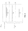
- Fig. 2 shows the lowest two layers in the OSI model 200, i.e. the PHY layer 202 and the data link layer 204.
- the PHY layer (first layer in the OSI model) is divided into three layers or PHY-sublayers.
- the first PHY-sublayer is the PMD (physical media dependant) layer 206, which includes basic functionality such as symbol timing generation and recovery, encoding and decoding, modulation and demodulation, echo cancellation (if implemented) and line equalization, link startup, and physical layer overhead (superframing). Additionally, the PMD layer may generate or receive control messages via an overhead channel.
- PMD physical media dependant
- the next PHY-sublayer is the PMS-TC (physical media specific - transmission convergence) layer 208 which is connected to the PMD layer through the ⁇ interface.
- the PMS-TC layer 208 is a management plane and provides management primitive indications to management entities in the CO and CPE modems.
- the PMS-TC layer 208 provides in addition functionality such as generation of frames and synchronization of frames, (de)scrambling, Reed-Solomon coding and interleaving.
- the third PHY-sublayer is the TPS-TC (transmission protocol specific-transmission convergence) layer 210 which is connected to the PMS-TC layer 208 through an ⁇ -interface (alpha-interface) at the Central Office Site or a ⁇ -interface (beta-interface) at the subscriber site.
- the TPS-TC layer 210 provides functionality such as packetizing into frames, organizing of the bearer channels, multiplexing.
- the TPS-TC layer 210 is connected to the data link layer 202 (layer 2 in the OSI model) by the ⁇ -interface (gamma-interface).
- Physical layer retransmission is one technique proposed in this application to increase the quality of video and other similar applications over DSL.
- some aspects of the present invention relate to several flavours of retransmission protocols in which erroneous (corrupted) data is re-sent or re-transmitted.
- These retransmission protocols may be included a retransmission layer inserted into the protocol stack described above.
- retransmission modules have been specific to the "Gamma-Layer” and "Alpha Layer” (and, thus, retransmission modules have not interchangeable between these layers).
- retransmission modules are provided that can be flexibly interchanged between different layers in the stack (e.g., between the "Gamma Layer” and the "Alpha Layer.)
- ARQ Automatic Retransmission reQuest
- These ARQ protocols which re-send erroneous (corrupted) data, may be included a retransmission layer inserted into the protocol stack described above. More particularly, some embodiments of the invention propose a combination of "Gamma-Layer Retransmission” and "Alpha Layer Retransmission” schemes, which have previously been located at different sub-layers of the protocol stack.
- One embodiment of the invention proposes a retransmission scheme which can be implemented above the physical layer of the DSL system.
- the invention is based on grouping several data bytes together in to a container and using a sequence ID for this container as a reference for retransmission.
- the retransmission scheme can be implemented between the gamma interface and the alpha/beta interface, or can be implemented between any other interface layers in the OSI stack which is suitable for the implementation.
- This generic approach is possible because there is no direct relation of the scheme to packets/cells or code words etc.
- the data unit contains a byte stream and is not dependent of the completeness of the TC payload.
- the invention also enables classification of data in to data streams that are eligible for retransmission and not eligible for retransmission.
- the proposed scheme uses a low mean over head data rate when compared to the state of the art systems, resulting in an overall near optimal retransmission technique.
- a stream of data payload (PL) units 300 is supplied, for example, by the gamma interface of the first transceiver unit 102a (transmitter).
- Each PL unit may include an Ethernet packet or ATM cell, among types of data unit.
- each PL unit includes header information that identifies that unit as either non-eligible for retransmission (NEL) or eligible for retransmission (EL).
- NEL non-eligible for retransmission
- EL eligible for retransmission
- real-time voice data could be classified as NEL because retransmission would result in unacceptable latency (delay) between participants in the conversation.
- video or FTP data could be classified as EL because it could be buffered without causing unacceptable latency.
- a container generator 302 receives the data unit stream and groups the byte stream into containers 304.
- each container includes the same number of data units, but in other embodiments the containers can include different numbers of data units so long as the differing lengths are now to both transmitter and receiver.
- the container generator 302 may group the data units to generate a container that includes NEL data units 306, EL data units 308, and a unique container identifier (CID) 310.
- the CID contains a sequence identifier (SID) 312 plus the number of complete PL units (e.g., bytes, cells or packets). If there is not enough data to fill a complete container, the container generator can insert idle data /filler cells 314 to complete a container.
- Each container 304 is stored along with its associated embedded overhead channel (EOC) byte in a Retransmission Buffer (Re TX Buffer) 316.
- the ReTX Buffer stores these containers 304 even after they are transmitted (likely up to some expiration time), thereby enabling retransmission.
- a second controller 318 appends redundancy bytes 320 to each DTU to allow for error detection and/or error correction by the receiver.
- redundancy bytes are based on Reed-Solomon (RS)-check bytes; while in case of PTM, these redundancy bytes are based on cyclic redundancy checks (CRC).
- RS Reed-Solomon
- CRC cyclic redundancy checks
- DTUs 322 are transmitted over the subscriber line 106.
- Noise on the line may corrupt DTUs on the line, as indicated by the "X"s on two of the DTUs.
- the second transceiver unit (receiver) 102b then receives the DTUs and uses the redundancy bytes to detect whether errors are present. If possible, the receiver can also use the redundancy bytes to correct these errors. For errors that cannot be corrected, the retransmission request controller 330 analyzes the received data units in the receiver's retransmission buffer 332 and notes which containers need to be retransmitted. For example, in Fig. 3 , the containers 1 and 3 are not found in the retransmission buffer 332, and therefore should be retransmitted. The retransmission request controller 330 then sends a retransmission request 340 back to the transmitter 102a indicating which DTUs need to be re-transmitted.
- the retransmission request 340 can specify the CIDs of the corrupted containers. This information can be included, for example, in the RRC field. In addition, in some embodiments this information can be piggybacked with upstream payload data (USPL) messages that are transmitted to the transmitter 102a, along with the EOC and redundancy information.
- USPL upstream payload data
- the retransmission controller 342 Upon receiving the retransmission request 340, the retransmission controller 342 identifies the requested container, which is stored in the retransmission buffer 316. This can be accomplished by the retransmission controller 342 using a look-up table that correlates the containers address in the retransmission buffer with the CID. Notably, the retransmission controller than pulls the EL from the relevant container, and then appends new data (e.g., EL data, NEL data and/or fill data) to the remainder of the retransmitted container.
- new data e.g., EL data, NEL data and/or fill data
- Fig. 4 shows another embodiment, where a simplified retransmission encapsulation is used.
- a container is packed with contiguous bytes of EL data up to the container size, and labeled with an SID. If NEL data is encountered before a current container is completely full, the current container is labeled with an SID directly after the last EL data, and then the NEL is packed into a separate container. If uncorrectable data is encountered by the receiver, the receiver in this instance can request containers that include only EL data (i.e., the requested containers do not include NEL data). Therefore, this embodiment provides very low over head retransmission. This means for a very long contiguous packets (e.g., video packets, which are a typical case) only a minimum overhead insertion is required.
- EOC embedded overhead channel
- FIG. 5 shows a retransmission technique using an Ethernet packet as TC pay load.
- the Ethernet packet is fragmented and encapsulated with a sequence identifier, SID.
- SID sequence identifier
- the fragments are then packed into containers, where a tag field is associated with each fragment to indicate how the fragment boundaries are aligned with respect to the container boundaries.
- the tag field can also indicate the alignment of EL data and NEL data within a given fragment or between fragments, or can indicate the alignment of retransmitted data and newly transmitted data within a given fragment or between fragments.
- An overhead channel field is also associated with each container. After the containers are packed, redundancy bytes are then appended to the end of each container and the containers are transmitted over the line to the receiver.
- the receiver can provide the SID corresponding to the uncorrectable data back over the line to the retransmission unit of the transmitter.
- the retransmission unit can then retransmit the necessary data associated with the SID. Since the transmitter and receiver are synchronized in DSL, there is no necessity to "label" the container and transmit the container label. In all DSL system various counters are maintained for performance monitoring, as long as the transmitter and receiver keep a counter of the codewords there is no need to transfer any label other than the SID.
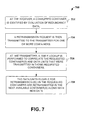
- Fig. 7 shows one retransmission scheme and is now briefly discussed. While the method 700 illustrated below is illustrated and described as a series of acts or events, it will be appreciated that the present invention is not limited by the illustrated ordering of such acts or events. For example, some acts may occur in different orders and/or concurrently with other acts or events apart from those illustrated and/or described herein, in accordance with the invention. In addition, not all illustrated acts or events may be required to implement a methodology in accordance with the present invention.
- a corrupted container is identified by RS evaluation.
- a retransmission request is then transmitted to the transmitter for one or more containers.
- a table lookup is performed to correlate the requested container(s) and data units that were transmitted in those requested containers.
- the EL data units in the requested containers are retransmitted in the next available container(s).
- the retransmission request channel can be realized with a protocol with fixed number of bytes per symbol requesting the corrupted container. In this case, the receiver needs to request the FEC codeword number of containers per symbol. In other embodiment, the retransmission request channel can be realized with a pre-empted short fragment/cell.
- a container may have the following properties: each container is one or more FEC codeword like Reed-Solomon Codeword D Known length of the FEC (may be changed by OLR) with block-interleaving or GCI D Embedding of fragments/cells similar to the 64/65 block (instead of a size of 65 bytes it can be up to 255 bytes, or even more) D Containers are evaluated for errors (using RS redundancy). Container number is used for identification in retransmission request D Container number not transmitted in the container. The receiver counts the containers from activation D Possibility to do "Container repetition” instead of "frame blanking", thereby temporarily stopping or limiting transmission during intervals in which repetitive electrical impulse noise (REIN) occurs.
- FEC codeword like Reed-Solomon Codeword
- ⁇ Fragment/Cell function D Contains an SID for re-ordering - does not need to be contiguous so bonding fragments can be used D Field to identify membership to the class of protection (service specific) D No CRC needed due to RS of Container D The fragment/cell is the actual retransmission unit. On RTX request a new Container is assembled depending on capacity and on the protection class of fragments in the requested container. D Retransmitted fragments/cells can optionally contain the original container number to equalize the bonding delay.
- the data eligible for retransmission contains unique container IDs and the non retransmission data eligible data container contains the ID of the previous eligible container.
- the retransmission system can identify the corrupted data using error detection / correction technique and if the data that is corrupted belongs to the eligible data stream.
- One advantage with the scheme is that only the eligible stream carries unique IDs and non eligible data carries the ID of the eligible container. So, if a non eligible data container is lost, the receiver will not even request the lost data because there must have been an earlier container received successfully with eligible data.
- the proposed embodiment is a very flexible retransmission scheme that does not limit the size of the data unit.
- the retransmission scheme uses "just enough" overhead when needed, because only the eligible data is encapsulated. It may be argued that the above property can lead to additional overhead whenever there a mix of eligible and non eligible data, but from the application and practical scenarios this is seldom the case, because the eligible data like video are usually contiguous long data packets.
- the DMT system is a symbol synchronous system where container information is available and synchronized at both transmitter and receiver.
- the invention does not restrict the data unit and the container to have one to one mapping.
- the invention allows decoupling of the TC layer data size (data units) and the physical layer data size (container) and can accommodate varying data unit sizes and varying number of data units per container.
- Some embodiments of the proposed invention can be applied for cases where TC layer bonding is used, for example ATM, PTM etc.
- the invention can be applied to any system with a known frame structure to reduce the overhead for the retransmission scheme. For example, by using the DMT symbol as reference points instead of using containers (RS codewords) the overhead can be reduced. If there are multiple code words in a DMT symbol, the number of retransmission request bytes are also reduced.
- RS codewords containers
- the contents of the containers may be unique, i.e. the container itself is transmitted only once and never retransmitted, but the eligible content of the container is retransmitted on request in a new container.
- this invention describes a system where information is conveyed from one modem to the other identifying the corrupt information, and the transmitting modem, based on the corrupt information the transmitter identifies the container associated with data unit and request retransmission of the data unit by sending necessary information, example container number. Based on the retransmission request information, the transmitter identifies the data units that are requested using a look up table that contains the correlation information of the data unit and the container.
- retransmission eligibility classification examples include, but are not limited to: application type, eligible under certain external conditions, (e.g., noise); never eligible; always eligible; and/or eligible for retransmission for a time window.
- application type eligible under certain external conditions, (e.g., noise); never eligible; always eligible; and/or eligible for retransmission for a time window.
- the eligibility criterion for classes of data associated with the retransmission can be changed dynamically based on external criterions like, noise characteristics.
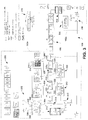
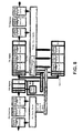
- Fig. 8 illustrates a gamma layer data path for the ATM-TC layer. More particularly, Fig. 8 illustrates transmission schemes for normal transmission TX, normal transmission RX, retransmission TX, and retransmission RX.
- a normal transmission TX scheme works according to the following acts as illustrated in Fig. 8 .
- ATM cells from the system interface are classified into eligible and non eligible for retransmission.
- the gamma+ retransmission function inserts an individual SID_cell1 into ATM cells eligible for retransmission and SID_cell2 into ATM cells non-eligible for retransmission.
- All ATM cells are forwarded to the modified TPS-TC and then to the PMS-TC.
- the PMS-TC builds mux data frames (MDF) by adding the sync byte in the usual way.
- MDF mux data frames
- the overhead channel bytes are stored in the TX retransmission buffer
- the PMS-TC scrambler may be switched off in certain embodiments.
- PMS - TC appends SID_frame to MP ⁇ MDF .
- the gamma+ DTU is defined by Dp ⁇ (Mp ⁇ MDF + SID_frame).
- the gamma+ retransmission function keeps track of the correlation between gamma+ DTUs including the overhead bytes identified by SID_frame and ATM cells eligible for retransmission identified by SID_cell1 (e.g. by maintaining a SID translation table).
- the receiver can take into account additional constraints in the framing parameter generation.
- the codeword is forwarded to the Reed-Solomon encoder as usual, which adds an amount of RS checkbytes for error detection with sufficiently low misdetection probability.
- Block interleaving could also be used in some implementations.
- a normal transmission RX scheme works according to the following acts as illustrated in Fig. 8 .
- the Reed-Solomon decoder checks whether the received RS codeword is correct or in error. This information has to be forwarded to the OHC playout buffer handling and to the 'eligible cells' playout buffer handling.
- the receiver If RS codewords are received in error, the receiver requests the corresponding range of corrupted gamma+ DTUs [last valid_SID_frame; first valid_SID_frame] from the transmitter. It will be appreciated that details of the retransmission request policy are more complex, but not expected to influence the basic feasibility.
- the PMS-TC forwards OHC bytes to the OHC playout buffer.
- the RS codewords are forwarded to the ATM-TC for delineation.
- the retransmission function drops cells that are expected (The amount of cells expected to be in error is larger than the amount of cells contained in corrupt codewords due to the PMS-TC scrambler) to be in error based on the Reed-Solomon check.
- Cells non-eligible for retransmission are immediately forwarded to the higher layer, while cells eligible for retransmission are forwarded to the playout buffer
- a retransmission TX scheme works according to the following acts as illustrated in Fig. 8 .
- the transmitter When the receiver requests a range of corrupted gamma+ DTUs [last valid_SID_frame; first valid_SID_frame], the transmitter has to identify the corresponding cells eligible for retransmission and the corresponding overhead bytes (e.g. by searching the corresponding range of SID_cell1 in the SID translation table).
- the cells in the range of [last_valid_SID_cell1; first_valid_SID_cell1] are fetched from the retransmission buffer and forwarded to the ATM-TC. Also the corresponding overhead bytes are fetched from the retransmission buffer and inserted into the mux data frames.
- the PMS-TC appends SID_frame to the Mp ⁇ MDF with retransmitted cells and overhead bytes. That is in detail, that the retransmitted DTU is newly-made and not necessarily identical to the DTU that was corrupted. In certain embodiments it may happen, that the amount of to be retransmitted cells does not fit into an integer amount of DTUs. In this case, the remaining cells may be filled with either Idle cells or new cells from the system interface.
- the retransmission DTU is forwarded to the Reed-Solomon encoder, which generates new RS checkbytes.
- a retransmission RX scheme works according to the following acts as illustrated in Fig. 8 .
- the retransmitted DTU is processed in the same way as a normal DTU.
- the extracted OHC bytes are forwarded to the OHC playout buffer.
- the OHC playout buffer inserts them into the message at the appropriate positions
- the retransmitted cells are forwarded to the playout buffer.
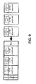
- Fig. 9 illustrates the gamma layer with DTU for the ATM-TC layer. As shown in Fig. 9 , if the RS codeword contains an integer amount of ATM cells, the DTUs of alpha and gamma retransmission become similar:
- the gamma+ DTU is constructed by Dp ⁇ (Mp ⁇ Kp + SID_frame) (In case of block interleaving, the parameter Dp is equal to the interleaver depth. Without interleaving or in case of convolutional interleaving, Dp is an independent parameter).
- Dp ⁇ (Mp ⁇ Kp + SID_frame) can contain an integer amount of ATM cells. This is the basic idea for combining retransmission at alpha and gamma.
- the gamma+ DTU for ATM-TC contains two independent types of SIDs, that are similar to alpha (SID_frame) and gamma for ATM-TC (SID_cell), respectively:
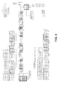
- Fig. 10 illustrates a gamma layer data path for the 64/65o-TC layer. More particularly, Fig. 10 illustrates transmission schemes for normal transmission TX, normal transmission RX, retransmission TX, and retransmission RX over the 64/65o-TC layer.
- the gamma+ data path for 64/65o-TC is similar to the data path for ATM-TC. Major difference is the variable length of fragments, that requires to maintain fragment delineation boundaries.
- a normal transmission TX scheme works according to the following acts as illustrated in Fig. 10 .
- Packets from the system interface are classified into eligible and non-eligible for retransmission.
- the gamma+ retransmission performs fragmentation of packets according to the PAF fragmentation function (ITU-T G.998.2).
- the gamma+ retransmission function appends an individual SID_fragm1 to fragments eligible for retransmission and SID_cell2 to fragments non-eligible for retransmission.
- the retransmission function keeps track of fragment boundaries in 65o words by monitoring the 64/65o-TC control bytes, especially Ck. This information can be maintained in the SID translation table to correlate DTUs in error with corrupted fragments eligible for retransmission.
- a normal transmission RX scheme works according to the following acts as illustrated in Fig. 10 .
- the Reed-Solomon decoder checks whether the received RS codeword is correct or in error. This information has to be forwarded to the OHC playout buffer handling and to the 'eligible cells' playout buffer handling.
- the receiver If RS codewords are received in error, the receiver requests the corresponding range of corrupted gamma+ DTUs [last valid_SID_frame; first valid_SID_frame] from the transmitter. It will be appreciated that details of the retransmission request policy are more complex, but not expected to influence the basic feasibility.
- the PMS-TC forwards OHC bytes to the OHC playout buffer.
- the RS codewords are forwarded to the 64/65o-TC for delineation.
- the 64/65o-TC drops all fragments with CRC-16 (32) in error (within the misdetection probability of 2 ⁇ 16/2 ⁇ A32). Since fragments are not aligned to 65o words, the first fragment and the last fragment may belong to the range of corrupted codewords only partially. These partially corrupted fragments will be also dropped due to CRC check and have to be retransmitted.
- the retransmission function may implement an additional drop for all fragments that are expected to be in error based on the Reed-Solomon check, optional.
- Fragments non-eligible for retransmission are immediately forwarded to the higher layer, while fragments eligible for retransmission are forwarded to the playout buffer.
- a retransmission TX scheme works according to the following acts as illustrated in Fig. 10 .
- the transmitter When the receiver requests a range of corrupted gamma+ DTUs [last valid_SID_frame; first valid_SID_frame], the transmitter has to identify the corresponding fragments eligible for retransmission and the corresponding overhead bytes (e.g. by searching the corresponding range of SID_fragm1 in the SID translation table)
- the fragments in the range of [last_valid_SID_cell1; first_valid_SID_cell1] are fetched from the retransmission buffer and forwarded to the 64/65o-TC.In order to accelerate retransmission, an ongoing transmission of a fragment may be pre-empted. Since fragments are sent again to the 64/65o-TC, the delineation of retransmitted fragments is different to the delineation in the first transmission. Therefore, Ck* bytes will be in general different to Ck and can be updated in the SID translation table.
- a retransmission RX scheme works according to the following acts as illustrated in Fig. 10 .
- the retransmitted DTU is processed in the same way as a normal DTU.
- the extracted OHC bytes are forwarded to the OHC playout buffer as in gamma+ for ATM-TC
- the retransmitted fragments are forwarded to the playout buffer.
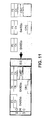
- Fig. 11 illustrates the gamma layer with DTU for the 64/65o layer.
- the gamma+ DTU can contain an integer amount of 65octet words in case of 64/65o-TC. It will be appreciated that fragment boundaries need not be aligned to 65o words or to RS codewords.
- the gamma+ DTU for 64/65o-TC contains two independent types of SIDs, that are similar to alpha (SID_frame) and gamma for 64/65o-TC (SID_fragm), respectively:
- Fig. 12 illustrates a SID Translation Table for Gamma layer with ATM-TC. Due to the restriction of framing parameters to values, that an integer amount m of ATM cells is contained in a gamma+ DTU, the correlation between SID_frame and SID_cell is unambiguous.
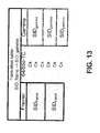
- Fig. 13 illustrates a SID Translation Table for Gamma layer with 64/65o-TC. Due to the variable length of fragments, the correlation between SID_frame and SID_fragm is not unambiguous. The alignment of fragment boundaries is maintained by the 64/65o-TC with the Ck byte. A similar correlation as in ATM-TC may be constructed by storing the Ck byte in the SID translation table. The restriction of framing parameters to values, that an integer amount n of 65o words is contained in a gamma+ DTU, ensures an unambiguous correlation between SID_frame and n ⁇ Ck.
- a fragment eligible for retransmission may be mapped only partially to the first or last codeword. Such fragments can be treated as if they belong completely to the corresponding SID_frame.
- the Reed-Solomon decoder can be used as detector for both ATM-TC and 64/65o-TC.
- OHC-INP The PMS-TC OAM channel or in DSL terms simply spoken overhead channel OHC is not impulse noise protected by ReTx in case of ⁇ -ReTx.
- a simple solution with OHC-INP can be as follows. 1.) CRC-8 is calculated over (SEQ-1) bytes as mentioned in gamma+ spec, i.e. only over the overhead channel bytes, exclusive FEC framer packetized TPS-TC data. Table 7-14/G.992,3 - Overhead channel structure depending on SEQ p Octet number Information SEQ p length Case if p MSG and latency path #p is not the lowest latency path according to the definition in this clause 2 0 CRC octet 1 Reserve for use by ITU-T.
- This octet shall be set to FF 10 in all lstaney paths Case if p MSG lp and latency path is the lowest latency path 6 0 CRC octet 1,2,3,4 Bit-oriented portion of overhead channel 5 Reserved for sis by ITU-T
- This octet shall be set to FP k is all latency path Case if p** MSG LP and latency path is not the lowest latency path according to the definition in this clause MSG c + 2 0 CRC octet 1 Reserved for use by ITU-T .
- This octet shall be set to FF 10 is all latency path 2, 3, Message-oriented portion of overhead channel MSG Case if p - MSG LP and latency path #p is the lowest latency path according to the definition in this clause MSG c + 6 0 RC octet 1,2,3, 4 Bit-cricated portion of overhead channel 5 Reserved for use by ITU-T
- MSG c 6,7,... MSG c +5- Message oriented portion of overhead channel 2.
- Some embodiments relate to a system capable of receiving retransmission request in both alpha and gamma layer and sending the requested data to the far end receiver in the same or a different layer.
- Some embodiments relate to a transmitter containing the correlation information between the data units and the container.
- Some embodiments relate to correlation information between the data units on one layer, for example gamma interface and the container on another layer, for example at alpha interface is exploited to enable retransmission at any layer regardless of the retransmission implementation layer on the other modem. For example can be used to maintain the correlation information.
- Some embodiments relate to a retransmission scheme, where the corrupted data is identified by an error detection mechanism and the retransmission request is associated with a data unit.
- the retransmission request can be made using a data unit identifier.
- Some embodiments relate to a transmitter that uses the correlation information between the data transfer unit and container to select the appropriate eligible data units for retransmission.
- Some embodiments relate to a transmitter containing the correlation information between the data units and the container.
- Some embodiments relate to correlation information between the data units on one layer, for example gamma interface and the container on another layer, for example at alpha interface is exploited to enable retransmission at any layer regardless of the retransmission implementation layer on the other modem.
- Some embodiments relate to a retransmission scheme, where the corrupted data is identified by an error detection mechanism and the retransmission request is associated with a container unit.
- the retransmission request can be made using a container unit identifier.
- Some embodiments relate to a transmitter that uses the correlation information between the data transfer unit and container to select the appropriate eligible data units for retransmission.
- Some embodiments relate to a system capable of receiving retransmission request in both alpha and gamma layer and sending the requested data to the far end receiver in the same or a different layer.
Landscapes
- Engineering & Computer Science (AREA)
- Computer Networks & Wireless Communication (AREA)
- Signal Processing (AREA)
- Multimedia (AREA)
- Computer Security & Cryptography (AREA)
- Detection And Prevention Of Errors In Transmission (AREA)
- Communication Control (AREA)
- Data Exchanges In Wide-Area Networks (AREA)
Applications Claiming Priority (8)
| Application Number | Priority Date | Filing Date | Title |
|---|---|---|---|
| US97683907P | 2007-10-02 | 2007-10-02 | |
| US97680807P | 2007-10-02 | 2007-10-02 | |
| US98413207P | 2007-10-31 | 2007-10-31 | |
| US98416207P | 2007-10-31 | 2007-10-31 | |
| US99180907P | 2007-12-03 | 2007-12-03 | |
| US99181207P | 2007-12-03 | 2007-12-03 | |
| US9663608P | 2008-09-12 | 2008-09-12 | |
| US9657008P | 2008-09-12 | 2008-09-12 |
Publications (2)
| Publication Number | Publication Date |
|---|---|
| EP2045951A2 true EP2045951A2 (de) | 2009-04-08 |
| EP2045951A3 EP2045951A3 (de) | 2012-08-29 |
Family
ID=40509784
Family Applications (1)
| Application Number | Title | Priority Date | Filing Date |
|---|---|---|---|
| EP08165691A Ceased EP2045951A3 (de) | 2007-10-02 | 2008-10-02 | Rückübertragungsschema für Kommunikationssysteme |
Country Status (2)
| Country | Link |
|---|---|
| US (1) | US8788901B2 (de) |
| EP (1) | EP2045951A3 (de) |
Cited By (1)
| Publication number | Priority date | Publication date | Assignee | Title |
|---|---|---|---|---|
| CN110611550A (zh) * | 2018-06-14 | 2019-12-24 | 诺基亚通信公司 | 用于全双工通信的dtu编码和解码 |
Families Citing this family (13)
| Publication number | Priority date | Publication date | Assignee | Title |
|---|---|---|---|---|
| US8468427B2 (en) * | 2007-10-02 | 2013-06-18 | Lantiq Deutschland Gmbh | Retransmission scheme for communication systems |
| WO2009120825A1 (en) * | 2008-03-26 | 2009-10-01 | Conexant Systems, Inc. | Systems and methods for protecting dsl systems against impulse noise |
| WO2010001474A1 (ja) * | 2008-07-03 | 2010-01-07 | 富士通株式会社 | 符号化装置、復号化装置、符号化方法、および復号化方法 |
| US20100088569A1 (en) * | 2008-10-05 | 2010-04-08 | Ikanos Communications, Inc. | Packet Retransmission |
| CN101729224A (zh) * | 2008-10-20 | 2010-06-09 | 富士通株式会社 | 传输数据生成装置和接收机 |
| US8413000B2 (en) * | 2008-12-02 | 2013-04-02 | Ikanos Communications, Inc. | Retransmission above the gamma interface |
| FR2943197B1 (fr) * | 2009-03-13 | 2015-02-27 | Thales Sa | Procede et dispositif de transmission robuste de flux de paquets de donnees a en-tetes compresses sans augmentation de debit |
| CN101860422B (zh) * | 2009-04-09 | 2014-02-19 | 华为技术有限公司 | 一种数字用户线路的数据传输方法、装置及系统 |
| US9628226B2 (en) | 2010-09-30 | 2017-04-18 | Qualcomm Incorporated | Block acknowledgement with retransmission policy differentiation |
| CN105637844B (zh) * | 2014-09-25 | 2018-09-21 | 华为技术有限公司 | 一种支持鲁棒性通道rc的编码调制方法及装置 |
| CN108809901B (zh) * | 2017-05-02 | 2021-05-04 | 华为技术有限公司 | 一种业务承载的方法、设备和系统 |
| CN113301605B (zh) * | 2021-05-18 | 2023-03-24 | 成都欧珀通信科技有限公司 | 消息传输方法、系统及相关装置 |
| US20230322366A1 (en) * | 2022-04-12 | 2023-10-12 | Embraer S.A. | Triplex Fully Redundant Fly-by-Wire Architecture |
Citations (4)
| Publication number | Priority date | Publication date | Assignee | Title |
|---|---|---|---|---|
| US5477550A (en) | 1993-03-08 | 1995-12-19 | Crisler; Kenneth J. | Method for communicating data using a modified SR-ARQ protocol |
| EP1077553A1 (de) * | 1999-03-10 | 2001-02-21 | Matsushita Electric Industrial Co., Ltd. | Sender/empfänger |
| WO2001056219A1 (en) * | 2000-01-25 | 2001-08-02 | Sharewave, Inc. | Retransmission scheme in wireless computer networks |
| EP1571773A2 (de) * | 2004-03-05 | 2005-09-07 | Kabushiki Kaisha Toshiba | Wiederübertragungsverfahren und entsprechende Einrichtung für ein Kommunikationssystem |
Family Cites Families (16)
| Publication number | Priority date | Publication date | Assignee | Title |
|---|---|---|---|---|
| JP3421208B2 (ja) | 1996-12-20 | 2003-06-30 | 沖電気工業株式会社 | ディジタル伝送システムおよび同期伝送装置におけるパス試験信号生成回路ならびにパス試験信号検査回路 |
| US6141784A (en) * | 1997-11-26 | 2000-10-31 | International Business Machines Corporation | Method and system in a data communications system for the retransmission of only an incorrectly transmitted portion of a data packet |
| EP1271955A3 (de) * | 2001-06-26 | 2007-05-02 | Koninklijke Philips Electronics N.V. | Verfahren zur Übertragung von Paketen mit Sendungswiederholung und Vorrichtung zur Steuerung der Übertragung von solchen Anforderungen |
| US7296204B2 (en) * | 2003-05-30 | 2007-11-13 | Wegener Communications, Inc. | Error correction apparatus and method |
| EP1513280A1 (de) * | 2003-09-05 | 2005-03-09 | Mitsubishi Electric Information Technology Centre Europe B.V. | Verfahren zur Datenübertragung mit Fehlererkennungsmechanismus, welches für unzuverlässige Netze und ausfallsichere Anwendungen bestimmt ist |
| US7225382B2 (en) * | 2004-05-04 | 2007-05-29 | Telefonakiebolaget Lm Ericsson (Publ) | Incremental redundancy operation in a wireless communication network |
| JP4440037B2 (ja) | 2004-08-11 | 2010-03-24 | 株式会社東芝 | 通信装置及び通信方法 |
| KR101313782B1 (ko) * | 2006-03-03 | 2013-10-01 | 코닌클리케 필립스 일렉트로닉스 엔.브이. | 무선 통신 시스템에서 데이터 블록을 송신 및 수신하기 위한 방법 및 장치 |
| US8381055B2 (en) * | 2006-09-13 | 2013-02-19 | Broadcom Corporation | System for communicating data in xDSL using data retransmission |
| US8320248B2 (en) * | 2006-09-13 | 2012-11-27 | Broadcom Corporation | Method and system for communicating data in xDSL using data retransmission |
| KR100984811B1 (ko) * | 2007-03-27 | 2010-10-01 | 삼성전자주식회사 | 데이터를 송수신하는 장치 및 방법 |
| US8127206B2 (en) * | 2007-09-13 | 2012-02-28 | Samsung Electronics Co., Ltd. | System and method for wireless communication of uncompressed video having reed-solomon code error concealment |
| US8179812B2 (en) * | 2007-10-02 | 2012-05-15 | Texas Instruments Incorporated | System and method for providing status reports of transmitted data packets in a data communications system |
| US8713393B2 (en) | 2007-10-02 | 2014-04-29 | Lantiq Deutschland Gmbh | Retransmission and retransmission request in data communication systems |
| US8351464B2 (en) | 2007-10-02 | 2013-01-08 | Infineon Technologies Ag | Retransmission in data communication systems |
| US8468427B2 (en) * | 2007-10-02 | 2013-06-18 | Lantiq Deutschland Gmbh | Retransmission scheme for communication systems |
-
2008
- 2008-10-02 US US12/244,037 patent/US8788901B2/en active Active
- 2008-10-02 EP EP08165691A patent/EP2045951A3/de not_active Ceased
Patent Citations (4)
| Publication number | Priority date | Publication date | Assignee | Title |
|---|---|---|---|---|
| US5477550A (en) | 1993-03-08 | 1995-12-19 | Crisler; Kenneth J. | Method for communicating data using a modified SR-ARQ protocol |
| EP1077553A1 (de) * | 1999-03-10 | 2001-02-21 | Matsushita Electric Industrial Co., Ltd. | Sender/empfänger |
| WO2001056219A1 (en) * | 2000-01-25 | 2001-08-02 | Sharewave, Inc. | Retransmission scheme in wireless computer networks |
| EP1571773A2 (de) * | 2004-03-05 | 2005-09-07 | Kabushiki Kaisha Toshiba | Wiederübertragungsverfahren und entsprechende Einrichtung für ein Kommunikationssystem |
Non-Patent Citations (3)
| Title |
|---|
| H.Y. SHIN ET AL.: "The study of QoS guarantee in the optical burst switching internet backbone", OPTICAL SWITCHING AND NETWORKING, vol. 2, 2006, pages 50 - 63, XP028009243, DOI: doi:10.1016/j.osn.2006.04.002 |
| LG ELECTRONICS INC: "RLC operation for real time IP services", 3GPP DRAFT; R2-020726 RLC OPERATION FOR REAL TIME IP SERVICES, 3RD GENERATION PARTNERSHIP PROJECT (3GPP), MOBILE COMPETENCE CENTRE ; 650, ROUTE DES LUCIOLES ; F-06921 SOPHIA-ANTIPOLIS CEDEX ; FRANCE, vol. RAN WG2, no. Kobe, Japan; 20020404, 4 April 2002 (2002-04-04), XP050120352 * |
| ZHENG H ET AL: "QoS aware mobile video communications", MILCOM 1999. IEEE MILITARY COMMUNICATIONS. CONFERENCE PROCEEDINGS (CAT. NO.99CH36341) IEEE PISCATAWAY, NJ, USA, IEEE, vol. 2, 31 October 1999 (1999-10-31), pages 1231 - 1235, XP010369821, ISBN: 978-0-7803-5538-5, DOI: 10.1109/MILCOM.1999.821400 * |
Cited By (1)
| Publication number | Priority date | Publication date | Assignee | Title |
|---|---|---|---|---|
| CN110611550A (zh) * | 2018-06-14 | 2019-12-24 | 诺基亚通信公司 | 用于全双工通信的dtu编码和解码 |
Also Published As
| Publication number | Publication date |
|---|---|
| US20090089641A1 (en) | 2009-04-02 |
| US8788901B2 (en) | 2014-07-22 |
| EP2045951A3 (de) | 2012-08-29 |
Similar Documents
| Publication | Publication Date | Title |
|---|---|---|
| EP2045951A2 (de) | Rückübertragungsschema für Kommunikationssysteme | |
| US8468427B2 (en) | Retransmission scheme for communication systems | |
| US8838525B2 (en) | Method for communicating data in xDSL using data retransmission | |
| US8713393B2 (en) | Retransmission and retransmission request in data communication systems | |
| US8848740B2 (en) | Retransmission in data communication systems | |
| EP2631811B1 (de) | Medium-zugriffsteuerschicht, die daten von mehreren empfangenen dateneinheiten in mehrere unabhängig sendbare blöcke einkapselt | |
| US10044473B2 (en) | Packet retransmission and memory sharing | |
| US11271682B2 (en) | Method and device for retransmission | |
| EP1901470B1 (de) | Verfahren und System zur Datenkommunikation in xDSL mit Datenrückübertragung | |
| US6075787A (en) | Method and apparatus for messaging, signaling, and establishing a data link utilizing multiple modes over a multiple access broadband communications network | |
| EP2154807B1 (de) | DSL Rückübertragungsverfahren und Einrichtung dafür | |
| US20160277153A1 (en) | Method and apparatus for packet retransmission in dsl systems | |
| US9300596B2 (en) | Method of packet encapsulation for multi-service operation from a distribution point | |
| CN101710854B (zh) | 用于通信系统的重发方案 |
Legal Events
| Date | Code | Title | Description |
|---|---|---|---|
| PUAI | Public reference made under article 153(3) epc to a published international application that has entered the european phase |
Free format text: ORIGINAL CODE: 0009012 |
|
| AK | Designated contracting states |
Kind code of ref document: A2 Designated state(s): AT BE BG CH CY CZ DE DK EE ES FI FR GB GR HR HU IE IS IT LI LT LU LV MC MT NL NO PL PT RO SE SI SK TR |
|
| AX | Request for extension of the european patent |
Extension state: AL BA MK RS |
|
| RAP1 | Party data changed (applicant data changed or rights of an application transferred) |
Owner name: LANTIQ DEUTSCHLAND GMBH |
|
| PUAL | Search report despatched |
Free format text: ORIGINAL CODE: 0009013 |
|
| AK | Designated contracting states |
Kind code of ref document: A3 Designated state(s): AT BE BG CH CY CZ DE DK EE ES FI FR GB GR HR HU IE IS IT LI LT LU LV MC MT NL NO PL PT RO SE SI SK TR |
|
| AX | Request for extension of the european patent |
Extension state: AL BA MK RS |
|
| RIC1 | Information provided on ipc code assigned before grant |
Ipc: H04L 1/00 20060101ALI20120723BHEP Ipc: H04L 1/18 20060101AFI20120723BHEP Ipc: H04L 1/16 20060101ALI20120723BHEP |
|
| RAP1 | Party data changed (applicant data changed or rights of an application transferred) |
Owner name: LANTIQ DEUTSCHLAND GMBH |
|
| 17P | Request for examination filed |
Effective date: 20130227 |
|
| 17Q | First examination report despatched |
Effective date: 20130327 |
|
| AKX | Designation fees paid |
Designated state(s): DE FR GB |
|
| STAA | Information on the status of an ep patent application or granted ep patent |
Free format text: STATUS: THE APPLICATION HAS BEEN REFUSED |
|
| 18R | Application refused |
Effective date: 20151013 |