EP2045923B1 - Dispositif à touche sensitive par effet capacitif éclairé et clavier de commande comprenant un tel dispositif - Google Patents
Dispositif à touche sensitive par effet capacitif éclairé et clavier de commande comprenant un tel dispositif Download PDFInfo
- Publication number
- EP2045923B1 EP2045923B1 EP08164996A EP08164996A EP2045923B1 EP 2045923 B1 EP2045923 B1 EP 2045923B1 EP 08164996 A EP08164996 A EP 08164996A EP 08164996 A EP08164996 A EP 08164996A EP 2045923 B1 EP2045923 B1 EP 2045923B1
- Authority
- EP
- European Patent Office
- Prior art keywords
- touch
- sensitive control
- light
- optical waveguide
- electrically insulating
- Prior art date
- Legal status (The legal status is an assumption and is not a legal conclusion. Google has not performed a legal analysis and makes no representation as to the accuracy of the status listed.)
- Active
Links
Images


Classifications
-
- H—ELECTRICITY
- H03—ELECTRONIC CIRCUITRY
- H03K—PULSE TECHNIQUE
- H03K17/00—Electronic switching or gating, i.e. not by contact-making and –breaking
- H03K17/94—Electronic switching or gating, i.e. not by contact-making and –breaking characterised by the way in which the control signals are generated
- H03K17/96—Touch switches
- H03K17/962—Capacitive touch switches
-
- D—TEXTILES; PAPER
- D06—TREATMENT OF TEXTILES OR THE LIKE; LAUNDERING; FLEXIBLE MATERIALS NOT OTHERWISE PROVIDED FOR
- D06F—LAUNDERING, DRYING, IRONING, PRESSING OR FOLDING TEXTILE ARTICLES
- D06F34/00—Details of control systems for washing machines, washer-dryers or laundry dryers
- D06F34/28—Arrangements for program selection, e.g. control panels therefor; Arrangements for indicating program parameters, e.g. the selected program or its progress
- D06F34/32—Arrangements for program selection, e.g. control panels therefor; Arrangements for indicating program parameters, e.g. the selected program or its progress characterised by graphical features, e.g. touchscreens
-
- D—TEXTILES; PAPER
- D06—TREATMENT OF TEXTILES OR THE LIKE; LAUNDERING; FLEXIBLE MATERIALS NOT OTHERWISE PROVIDED FOR
- D06F—LAUNDERING, DRYING, IRONING, PRESSING OR FOLDING TEXTILE ARTICLES
- D06F2105/00—Systems or parameters controlled or affected by the control systems of washing machines, washer-dryers or laundry dryers
- D06F2105/58—Indications or alarms to the control system or to the user
-
- H—ELECTRICITY
- H03—ELECTRONIC CIRCUITRY
- H03K—PULSE TECHNIQUE
- H03K2217/00—Indexing scheme related to electronic switching or gating, i.e. not by contact-making or -breaking covered by H03K17/00
- H03K2217/94—Indexing scheme related to electronic switching or gating, i.e. not by contact-making or -breaking covered by H03K17/00 characterised by the way in which the control signal is generated
- H03K2217/96—Touch switches
- H03K2217/9607—Capacitive touch switches
- H03K2217/960755—Constructional details of capacitive touch and proximity switches
- H03K2217/96076—Constructional details of capacitive touch and proximity switches with spring electrode
-
- H—ELECTRICITY
- H03—ELECTRONIC CIRCUITRY
- H03K—PULSE TECHNIQUE
- H03K2217/00—Indexing scheme related to electronic switching or gating, i.e. not by contact-making or -breaking covered by H03K17/00
- H03K2217/94—Indexing scheme related to electronic switching or gating, i.e. not by contact-making or -breaking covered by H03K17/00 characterised by the way in which the control signal is generated
- H03K2217/96—Touch switches
- H03K2217/9607—Capacitive touch switches
- H03K2217/960785—Capacitive touch switches with illumination
- H03K2217/96079—Capacitive touch switches with illumination using a single or more light guides
Definitions
- the present invention relates to a capacitive touch sensor device, and a control keyboard incorporating such a device.
- This touch sensitive device allows the illumination of said touch pad.
- the touch sensitive devices are used in particular in digital keyboards, for household electrical appliances, and for example a hob, a cooking oven or a hood, or a washing machine, a dryer or a washing machine. washing up.
- the electrically insulating body may be a glass, glass-ceramic or plastic plate constituting a control panel of an electrical appliance.
- the fact of placing a finger in a zone with regard to a touch pad has the effect of generating a variation of capacity depending in particular on the surface of the finger opposite a detection surface of the sensor. touch pad.
- the area of support of the sensitive key is identified by a screen printing made on a surface of the electrically insulating body.
- touch pad devices have the disadvantage of not allowing to know the state of the touch pad. The user can not know by looking at the control interface of an electrical device if the key is turned on or off.
- the document WO 2004/107062 A1 has an illuminated touch pad device.
- a document is also known EP1376872 which describes a lighting device of a control button provided on a transparent window.
- This lighting device comprises a light source, a light conductor and a sensitive switch mounted behind the control button.
- the light source is disposed remote from the control button and radiates into the light guide disposed under the window. The light is led into the light guide towards the control knob. And the light is conducted within an area between the touch sensor sensor and the control button.
- This document provides for the assembly of the light conductor by gluing on the glass and / or on the printed circuit carrying the light source.
- this lighting device of a control button has the disadvantage of using a bonding attachment means for connecting the light conductor to the glass and / or the printed circuit.
- the bonding bond causes disturbances in the operation of the sensitive switch not reliably and permanently detecting the user's finger when using the control button. These disturbances of operation of the sensitive switch are notably due to the air bubbles being housed inside the transparent adhesive tape deposited on the light conductor.
- this lighting device of a control button imposes a positioning of the fixed light guide relative to the glass or to the printed circuit and preventing any adjustment of the light guide vis-à-vis the control button.
- This lighting device does not allow to take into account the deformations of the printed circuit and the window to position the light guide vis-à-vis the light source.
- the gluing attachment of the light conductor on the printed circuit or the window does not allow the sensitive switch to adjust the positioning of said light conductor on said window.
- Fixing by gluing the light conductor on the printed circuit or the glass also does not guarantee a permanent contact between the glass, the light conductor and the sensitive switch so as to obtain operation without disturbing the control button.
- Such a lighting device does not make it possible to dispense with dielectrics that can be generated between the glass, the light conductor and the sensitive switch by an air gap causing disturbances in operation of the control button.
- the present invention aims to solve the aforementioned drawbacks and to provide a touch sensitive device for viewing the operating state of the sensitive key.
- the present invention is directed to a capacitive touch-sensitive device for detecting the presence of an element through an electrically insulating plate, the sensor pad comprising a solid detection face intended to be pressed against a lower surface of a light guide, said sensing face of said sensing key being opaque to light, and said sensing key being carried by a printed circuit board, the light guide having a solid light diffusion surface to be pressed against an inner surface of the electrically insulating plate.
- the touch-sensitive device makes it possible to illuminate an icon of a touch pad comprising a solid and opaque detection face without producing an opening for the passage of light in said detection face.
- the touch keys are all identical for all the functions that can be associated with them.
- the cost of obtaining the sensitive keys is minimized and allows to have a single reference.
- the light source makes it possible to illuminate at least one transparent or translucent part of the electrically insulating plate via the light guide and to display an icon disposed opposite the sensing face of the sensitive key.
- the icon represents a control function by passing light through said at least one transparent or translucent portion of the electrically insulating plate.
- the positioning of the light guide in contact with the electrically insulating plate by the elastic intermediate portion of the sensitive key makes it possible to avoid the creation of dielectrics in the form of an air gap between the electrically insulating plate, the light guide and the face sensing key.
- the sensitive key reliably and reliably detects an element placed opposite the sensing face of the sensing key through the electrically insulating plate.
- the contacting of the electrically insulating plate, the light guide and the touch pad is guaranteed by the elasticity of the intermediate portion of said touch pad.
- the contact of the electrically insulating plate, the light guide and the touch pad is ensured by pressing the surfaces to each other without having recourse to a fixing means.
- the icon represented on the electrically insulating plate is placed opposite the detection face of the sensitive key and thus makes it possible to avoid searching for the detection zone of the sensitive key.
- the positioning of the light source vis-à-vis a first light guide diffusion element makes it possible to avoid viewing a light spot through the electrically insulating plate.
- the first diffusion element diffuses light from the light source mounted on the printed circuit board into the light guide.
- the lower surface of the second diffusion element of the light guide is placed on the sensing face of the touch pad.
- the light guide is supported by the touch pad and pushed by the elastic intermediate portion of said touch pad.
- the light guide comprises two first light scattering elements extending between the printed circuit board and the electrically insulating plate, said first two light diffusion elements being respectively connected to one end. the second light guide diffusion element, and said first two light diffusion elements being respectively positioned vis-à-vis a light source.
- the light is diffused through two first diffusion elements respectively connected to a second diffusion element of the light guide in order to display the icon represented on the electrically insulating plate.
- the light diffused by the two light sources through the diffusion elements of the light guide is uniform.
- Such an arrangement of the diffusion elements of the light guide in the touch sensitive device makes it possible to avoid light losses and to guarantee a level of brightness determined by the intensity of the light sources.
- the touch pad and the light guide are placed inside a housing of a housing, said housing extending from the printed circuit board to the lower surface of the housing. electrically insulating plate.
- the light diffused by the light guide is channeled inside a housing of a housing for a touch-sensitive device without illuminating another touch-sensitive device that can be located nearby or without leaving a light passage. in the direction of a transparent or translucent part of the insulating electrical plate not belonging to said device.
- said at least one first diffusion element of the light guide comprises a rib sliding inside a groove formed on a wall of the housing housing.
- the light guide is positioned inside the housing of the housing and the displacement thereof is controlled.
- the elastic intermediate portion of the sensitive key thus moves the light guide inside the housing of the housing in a predetermined direction.
- the movement of the light guide is guided and ensures that the contact between the light guide and the electrically insulating plate is made over the entire solid light scattering surface of the light guide.
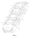
- FIG. 1 schematically illustrated a control keyboard comprising a plurality of touch sensitive devices according to the invention in an exploded view to view the means necessary for the implementation of the invention.
- the touch sensitive device 1 is adapted to detect the presence of an element, such as for example a finger of a user through an electrically insulating plate 2.
- the electrically insulating plate 2 is made of a material such as glass, glass ceramic or plastic.
- This electrically insulating plate 2 constitutes an element of the control of a domestic electrical appliance, of the type cooking appliance, hood, washing apparatus, ...
- the touch pad 4 has a full detection face 5 intended to be pressed against a lower surface 6 of a light guide 7.
- This detection face 5 is intended to come into contact with said surface 6 of the light guide 7.
- This detection face 5 is connected by an intermediate portion 8 to a base 9 intended to be fixed for example by connection pads 10 to the printed circuit board 3.
- the intermediate portion 8 has in this embodiment a certain flexibility so that the detection face 5 bears elastically against said surface 6 of the light guide 7 regardless of the lack of parallelism between the electrically insulating plate 2 and the printed circuit board 3.
- any type of touch pad 4 can be used as soon as it has a detection face 5 intended to come into contact with a lower surface 6 of the light guide 7 and that said detection face 5 is solid and opaque to the light.
- the sensitive key 4 is electrically connected to an electronic detection circuit for example carried by the printed circuit board 3.
- the touch pad 4 by capacitive effect is constituted by a Z-shaped leaf spring.
- the base 9 of the leaf spring substantially flat, forms with the detection face 5, the two end portions of the Z, the middle portion 8 being constituted by the oblique portion of the Z.
- the base 9 and the detection face 5 are substantially planar, and the oblique portion 8 is such that it allows a flexibility of the touch pad 4.
- the electronic detection circuit (not shown) comprises in particular a high frequency current generator and a means for measuring the variation of this current in the electrical circuit formed through the sensitive key 4 connected to the earth during the presence of a finger of the user next to this sensitive key 4.
- the capacitive touch sensor device 1 makes it possible to detect the presence of an element through an electrically insulating plate 2.
- the detection face 5 of the sensitive key 4 is opaque to light.
- the detection face 5 has no opening for the passage of light in order to guarantee the sensitivity of the touch pad 4.
- An opening in the detection face 5 has the effect of damaging the capacitive effect of the touch pad 4 and reducing the ease of control of a household electrical appliance comprising a touch sensitive device 1 by capacitive effect.
- the detection face 5 is made without perforations or at least one opening for the passage of light so as to standardize the touch pad 4 for all the controls of a domestic electrical appliance.
- the single sensor 4 is adapted to be put into operation irrespective of the control function and to be assembled on any printed circuit board 3.
- the detection face 5 does not need a customization to allow the backlighting of the sensitive key 4.
- the sensitive key 4 is carried by a printed circuit board 3.
- the light guide 7 has a solid light diffusing surface 11 intended to be pressed against an inner surface 12 of the electrically insulating plate 2, and generally against a surface intended to be disposed inside an apparatus, which is not visible. nor accessible by the user.
- the touch sensitive device 1 comprises at least one light source 13 assembled on the printed circuit board 3 and placed opposite at least one first diffusion element 14 of the light guide 7.
- Said at least one first diffusion element 14 of the light guide 7 is connected to a second diffusion element 15 of the light guide 7.
- Said second diffusion element 15 of the light guide 7 comprises the lower surface 6 and the solid light diffusing surface 11 of said light guide 7.
- Said second diffusion element 15 of the light guide 7 is positioned between the sensing face 5 of the sensing key 4 and the lower surface 12 of the electrically insulating plate 2.
- Said solid diffusion surface of the light 11 is pressed against the inner surface 12 of the electrically insulating plate 2 by an elastic intermediate portion 8 of the sensitive key 4.
- the light diffusing surface 11 is full so as to avoid the formation of an air gap between the electrically insulating plate 2 and the light guide 7.
- At least one transparent or translucent portion (not shown) of the electrically insulating plate 2 is formed opposite the opaque detection face 5 of the sensitive key 4 to allow the passage of the light emitted by said at least one light source 13 and diffused through the light guide 7.
- the shape of said at least one transparent or translucent part of the electrically insulating plate 2 makes it possible to define the shape of the illumination of the touch sensitive device 1.
- At least one icon (not illustrated) shown on the electrically insulating plate 2 is formed on at least a part of the zone defined by the projection of the opaque detection face 5 of the sensitive key 4 on said electrically insulating plate 2.
- the solid light diffusion surface 11 of the light guide 7 covers at least the surface of said at least one icon shown on the electrically insulating plate 2.
- the touch sensitive device 1 makes it possible to illuminate an icon of a sensitive key 4 comprising a full detection face 5 that is opaque to light without making an opening for the passage of light in said detection face 5.
- the sensor keys 4 are all identical for all the functions that can be associated with them. The cost of obtaining the touch keys 4 is minimized and allows to have a single reference.
- the light source 13 makes it possible to illuminate at least one transparent or translucent part of the electrically insulating plate 2 by means of the light guide 7 and to display an icon disposed opposite the detection face 5 of the sensitive key 4
- the icon represents a control function by passing light through said at least one transparent or translucent portion of the electrically insulating plate 2.
- the positioning of the light guide 7 in contact with the electrically insulating plate 2 by the elastic intermediate portion 8 of the sensitive key 4 makes it possible to avoid the creation of dielectrics in the form of an air gap between the electrically insulating plate. 2, the light guide 7 and the detection face 5 of the sensitive key 4.
- the sensitive key 4 safely and reliably detects an element placed vis-à-vis the detection face 5 of the sensitive key 4 through the electrically insulating plate 2.
- the contact of the electrically insulating plate 2, the light guide 7 and the touch pad 4 is ensured by pressing the surfaces to each other without resorting to a fixing means.
- the elasticity of the blade spring of the Z-folded sensor key 4 is adjusted so that it applies a sufficient force to the lower surface 6 of the light guide 7 so as to press the diffusion surface of the light 11 against the insulating electric plate 2.
- the central recess of the touch pad 4 makes it possible, during compression of the latter, to maintain the planar detection face 5 thanks to a rigidity greater than that of the intermediate part 8.
- the icon represented on the electrically insulating plate 2 is placed opposite the detection face 5 of the sensitive key 4 and thus makes it possible to avoid searching for the detection zone of the sensitive key 4.
- the positioning of the light source 13 vis-à-vis a first light-guiding element 14 prevents the visualization of a light point through the electrically insulating plate 2.
- the first element of Diffusion 14 diffuses the light of the light source 13 mounted on the printed circuit board 3 in the light guide 7.
- the lower surface 6 of the second diffusion element 15 of the light guide 7 is placed on the detection face 5 of the sensitive key 4.
- the light guide 7 is supported by the sensitive key 4 and pushed by the elastic intermediate portion 8 of said sensitive key 4.
- the lower surface 6 of the light guide 7 reflects the light in the direction of the electrically insulating plate 2.
- the light is diffused towards said at least one transparent or translucent part of the electrically insulating plate 2 in order to signal the operating state of the touch pad 4.
- Said reflective interior surface 6 makes it possible to obtain a better diffusion of the light towards the electrically insulating plate 2 and to improve the intensity of the light beam passing through said at least one transparent or translucent part of the electrically insulating plate 2.
- the light guide 7 comprises two first light scattering elements 14 extending between the printed circuit board 3 and the electrically insulating plate 2.
- Said first two light scattering elements 14 are respectively connected to one end of the second diffusion element 15 of the light guide 7.
- said first two light scattering elements 14 are respectively positioned vis-à-vis a light source 13.
- the light is diffused through two first diffusion elements 14 respectively connected to a second diffusion element 15 of the light guide 7 in order to display the icon represented on the electrically insulating plate 2.
- the light diffused by the two light sources 13 through the diffusion elements 14 and 15 of the light guide 7 is uniform.
- Such an arrangement of the diffusion elements of the light guide in the touch sensitive device 1 makes it possible to avoid losses of light and to guarantee a level of luminosity determined by the intensity of the light sources 13.
- the first two diffusion elements 14 make it possible to illuminate the touch-sensitive device 1 on each side of the touch pad 4 and to homogenize the light beam in the second diffusion element 15 of the light guide 7.
- the light guide 7 is constituted by two first diffusion elements 14 and a second diffusion element 15 so as to form a U upside down.
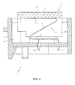
- An outer surface 16 of a connection zone 17 between said at least one first light scattering element 14 and the second light scattering element 15 of the light guide 7 is inclined at an angle ⁇ .
- the angle ⁇ of inclination of the outer surface 16 of a connection zone 17 between said at least one first light-diffusing element 14 and the second light-diffusing element 15 of the light guide 7 is order of 45 °.
- the angular orientation ⁇ illustrated in figure 5 the outer surface 16 of the connection zone 17 makes it possible to reflect the light coming from a first diffusion element 14 towards the second diffusion element 15 of the light guide 7. With such an inclination ⁇ , the diffused light intensity by the light guide 7 in the plate electrically insulating 7 is improved.
- the surfaces of the light guide 7 are covered with a light diffusing coating within said light guide 7 except for the reflective lower surface 6 and the solid surface of the light guide 7. light scattering 11 of said light guide 7.
- Said surfaces of the light guide 7 are covered with an aluminum adhesive paper so as to reflect the light of the light source 13 towards the interior of the light guide 7. In this way, the light beams of the light source bounce on the surfaces of the light guide covered with a coating diffusing the light.
- the lower surface 6 of the second diffusion element 15 of the light guide 7 can be covered with a film having a specific roughness making it possible to reflect the light beams vertically in the direction of the lower surface 11 of the electrically insulating plate 2.
- Said film covering the lower surface 6 of the second diffusion element 15 of the light guide 7 may be white in color.
- said at least one first diffusion element 14 of the light guide 7 comprises a recess 18 opposite said at least one light source 13.
- the recess 18 makes it possible to diffuse the light inside the first diffusion element of the light guide 7.
- the shape of the recess 18 is preferably of spherical shape.
- the radius of the recess 18 is of the order of 4mm.
- the recess 18 makes it possible to diffuse the light throughout the entire thickness of the first diffusion element 14 of the light guide 7 so as to avoid a main beam of high intensity and poorly illuminated areas of the light guide 7.
- At least two light sources 13 are placed on either side of a median plane M of the sensitive key 4.
- Said at least two light sources 13 are placed symmetrically with respect to a median plane M crossing the sensitive key 4 by its height. The light is evenly distributed within the light guide 7 of the touch sensitive device 1.
- said at least two light sources 13 are placed equidistant from the median plane M traversing vertically the sensitive key 4.
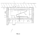
- the sensitive key 4 takes two positions, a first position, illustrated in FIGS. figures 3 and 5 , where the elastic intermediate portion 8 is uncompressed by the electrically insulating plate 2, and a second position, illustrated in FIGS. figures 4 and 6 , where the light guide 7 is in contact with the electrically insulating plate 2 so as to compress said elastic intermediate portion 8 of the sensitive key 4.
- the length L of said at least one first diffusion element 14 of the light guide 7 is smaller than the distance H separating the printed circuit board 3 from the detection face 5 of the sensitive key 4 when the elastic intermediate portion 8 of said touch pad is at rest.
- the light guide 7 has a travel dependent on the touch pad 4 to ensure the support of the entire light diffusing surface 11 when the electrically insulating plate 2 bears on the guide 7, and to prevent said at least one first diffusion element 14 from stressing on the printed circuit board 3.
- the sensitive key 4 and the light guide 7 are placed inside a housing 19 of a housing 20
- the housing 20 extends from the printed circuit board 3 to the lower surface 12 of the electrically insulating plate 2.
- the light diffused by the light guide 7 is channeled inside a housing 19 of a housing 20 for a touch-sensitive device 1 without illuminating another touch-sensitive device 1 that can be located near or without leaving a passage of light in the direction of a transparent or translucent part of the insulating electrical plate 2 not belonging to said device 1.
- the housing 20 delimits the area of the touch pad 4 by separating it by vertical walls of the environment around said housing 20.
- the housing 20 of the sensitive key 4 comprises four walls and preferably of black color to absorb the brightness that can be emitted by the two light sources 13.
- the black color of the housing 20 also allows, when the two light sources 13 are extinguished, to see no element through the electrically insulating plate 2.
- the light beam of the light sources 13 can not be diffused outside the housing 20.
- the bearing area of a touch pad 4 is delimited by a physical separation formed by vertical walls.
- the touch pad of a touch pad 4 is associated with a control function of an electrical appliance.
- said at least one first diffusion element 14 of the light guide 7 comprises a rib 21 sliding inside a groove 22 formed on a wall 23 of the housing 19 of the housing 20.
- the light guide 7 is positioned inside the housing 19 of the housing 20 and the displacement thereof is controlled.
- the elastic intermediate portion 8 of the sensitive key 4 thus moves the light guide 7 inside the housing 19 of the housing 20 in a predetermined direction.
- the displacement of the light guide 7 is guided and makes it possible to ensure that the contact between the light guide 7 and the electrically insulating plate 2 is made on the whole of the solid light scattering surface 11 of the light guide 7.
- the displacement of the light guide 7 under the effect of the elastic intermediate portion 8 of the sensitive key 4 of the printed circuit board 3 towards the outside of the housing 20 is limited by at least one stop 24 of the housing 19 of the housing 20 .
- the light guide 7 can not leave the housing 19 of the housing 20 as the electrically insulating plate 2 does not compress the touch pad 4 through the light guide 7.
- the light guide 7 is pushed a part by the elastic intermediate portion 8 of the sensitive key 4 and secondly held by the stop 24 of the housing 19 of the housing 20.
- the light guide is thus trapped between the housing 20 and the sensitive key 4 during assembly of the touch sensitive device 1 and thus facilitates this assembly.
- the touch sensitive device 1 can thus be prepared before assembly on a domestic electrical appliance.
- This touch sensitive device 1 can be assembled on a control panel in any direction and appropriate for each type of domestic electrical appliance, which can be vertical, horizontal or inclined.
- the light guide 7 of the sensitive key 4 is pushed by the detection face 5 of the sensitive key 4 towards the stop 24 of the housing 19.
- the light guide 7 is held inside the housing 19 of the housing 20 while leaving a freedom of movement along the guide rail formed in said housing 19 by the rib 21 and the groove 22.
- the blocking of the light guide 7 in the housing 19 is provided by the rib 21 of the light guide bearing on the abutment 24 formed on the wall 23 of the housing 19.
- a screen printing of the electrically insulating plate 2 can be performed on at least a portion of the zone defined by the housing 20 enclosing the sensitive key 4.
- At least one transparent or translucent portion of the electrically insulating plate 2 can be made above or around the opaque detection face 5 of said touch pad 4 to allow the passage of the light emitted by said minus two light sources 10.
- the light sources 13 are located at the right of said screen printing and outside said at least one transparent or translucent portion of the electrically insulating plate 2.
- the light diffusion of the two light sources 13 through the light guide 7 then of the said at least one transparent or translucent part of the electrically insulating plate 2 makes it possible to identify a support zone, an activated touch pad and the active keys. an interface with a user.
- An identification element of the touch pad 4 can be made by screen printing inside the shape of said at least one transparent or translucent part of the electrically insulating plate 2.
- the icon can be achieved by sparing a screen printing deposited on the electrically insulating plate 2.
- the identification element is located above the detection face 5 of the sensitive key 4.
- said at least one transparent or translucent part of the electrically insulating plate 2 and the screen printing of the identification element appear in such a way as to determine the location of said touch pad 4 .
- Said at least one transparent or translucent part of the electrically insulating plate 2 may comprise at least one frosted material to promote the diffusion of light through said electrically insulating plate 2.
- the light sources 13 may be light emitting diodes.
- the two light sources 13 are mounted inside the printed circuit board 3 according to a surface-mounted component (SMD) manufacturing method.
- SMD surface-mounted component
- This method of manufacturing the printed circuit board 3 reduces the cost of obtaining it.
- the light sources 13 are placed close to the base 9 of the sensitive key 4.
- the distance between a light source 13 and the base 9 of the sensitive key 4 is in a range extending between 1 mm and 5 mm, and preferably of the order of 2 mm.
- the light sources 13 are situated below the surface of the printed circuit board 3 comprising the touch pad 4.
- the touch sensitive device 1 can be integrated into any type of control keyboard for a domestic electrical appliance.
- a control keyboard comprises several touch-sensitive devices, and more particularly several sensitive keys enclosed in respective housings, the touch-sensitive keys 4 can all be mounted on the same printed circuit board 3.
- the housings can be made by a single piece of plastic.
- a display may optionally be placed inside the single piece forming the housings of the sensitive keys.
- the touch sensitive device 1 makes it possible to personalize the domestic electrical appliances by modifying only the icons represented on the electrically insulating plate 2.
- An identical printed circuit board 3 connected to several sensitive keys 4, according to the invention, can be used for different types of household electrical appliances. Thus, this set reduces the costs of obtaining a control keyboard comprising a plurality of touch sensitive devices.
Landscapes
- Engineering & Computer Science (AREA)
- Textile Engineering (AREA)
- Switches That Are Operated By Magnetic Or Electric Fields (AREA)
- Push-Button Switches (AREA)
- Input From Keyboards Or The Like (AREA)
- Electronic Switches (AREA)
- Switch Cases, Indication, And Locking (AREA)
Priority Applications (1)
| Application Number | Priority Date | Filing Date | Title |
|---|---|---|---|
| PL08164996T PL2045923T3 (pl) | 2007-09-27 | 2008-09-24 | Urządzenie podświetlanego pojemnościowego przycisku dotykowego oraz klawiatura sterująca zawierająca takie urządzenie |
Applications Claiming Priority (1)
| Application Number | Priority Date | Filing Date | Title |
|---|---|---|---|
| FR0706803A FR2921774A1 (fr) | 2007-09-27 | 2007-09-27 | Dispositif a touche sensitive par effet capacitif eclaire et clavier de commande comprenant un tel dispositif |
Publications (2)
| Publication Number | Publication Date |
|---|---|
| EP2045923A1 EP2045923A1 (fr) | 2009-04-08 |
| EP2045923B1 true EP2045923B1 (fr) | 2010-09-15 |
Family
ID=39362624
Family Applications (1)
| Application Number | Title | Priority Date | Filing Date |
|---|---|---|---|
| EP08164996A Active EP2045923B1 (fr) | 2007-09-27 | 2008-09-24 | Dispositif à touche sensitive par effet capacitif éclairé et clavier de commande comprenant un tel dispositif |
Country Status (6)
| Country | Link |
|---|---|
| EP (1) | EP2045923B1 (pl) |
| AT (1) | ATE481774T1 (pl) |
| DE (1) | DE602008002522D1 (pl) |
| ES (1) | ES2351076T3 (pl) |
| FR (1) | FR2921774A1 (pl) |
| PL (1) | PL2045923T3 (pl) |
Cited By (2)
| Publication number | Priority date | Publication date | Assignee | Title |
|---|---|---|---|---|
| DE202013011528U1 (de) | 2013-08-01 | 2014-11-03 | Diehl Ako Stiftung & Co. Kg | Berührungs- und/oder annäherungsempfindliche Eingabevorrichtung |
| DE102019000295A1 (de) * | 2019-01-16 | 2020-07-16 | Diehl Ako Stiftung & Co. Kg | Kapazitiver Berührungsschalter |
Families Citing this family (9)
| Publication number | Priority date | Publication date | Assignee | Title |
|---|---|---|---|---|
| US8669502B2 (en) * | 2009-07-27 | 2014-03-11 | Panasonic Corporation | Operation device and heating cooker using operation device |
| DE102009041653B4 (de) * | 2009-09-17 | 2018-11-22 | Continental Automotive Gmbh | Kapazitive Tastvorrichtung |
| DE102011006021A1 (de) * | 2011-03-24 | 2012-09-27 | E.G.O. Elektro-Gerätebau GmbH | Bedieneinrichtung für ein Elektrogerät |
| ES2425028B1 (es) * | 2012-03-29 | 2014-09-29 | Bsh Electrodomésticos España, S.A. | Dispositivo de aparato doméstico |
| KR20140121027A (ko) * | 2013-04-04 | 2014-10-15 | 엘지전자 주식회사 | 컨트롤패널, 컨트롤패널의 제어방법 및 상기 컨트롤 패널이 구비된 의류처리장치 |
| KR101623788B1 (ko) * | 2013-04-04 | 2016-05-24 | 엘지전자 주식회사 | 컨트롤패널 및 컨트롤패널이 구비된 의류처리장치 |
| US10382037B2 (en) | 2014-05-02 | 2019-08-13 | Illinois Tool Works Inc. | Modular capacitive touch switch system |
| CN220438903U (zh) * | 2023-04-26 | 2024-02-02 | 博西华电器(江苏)有限公司 | 触控面板及家用电器 |
| CN220438902U (zh) * | 2023-04-26 | 2024-02-02 | 博西华电器(江苏)有限公司 | 触控模组、触控面板及家用电器 |
Family Cites Families (4)
| Publication number | Priority date | Publication date | Assignee | Title |
|---|---|---|---|---|
| US5239152A (en) * | 1990-10-30 | 1993-08-24 | Donnelly Corporation | Touch sensor panel with hidden graphic mode |
| DE10123633A1 (de) * | 2001-05-09 | 2003-02-06 | Ego Elektro Geraetebau Gmbh | Sensorelement |
| EP1376872B1 (de) | 2002-05-07 | 2007-10-10 | Schott Ag | Beleuchtungseinrichtung für Schaltflächen |
| DE10326684A1 (de) * | 2003-06-03 | 2004-12-23 | Ego Control Systems Gmbh + Co. Kg | Sensorvorrichtung |
-
2007
- 2007-09-27 FR FR0706803A patent/FR2921774A1/fr not_active Withdrawn
-
2008
- 2008-09-24 ES ES08164996T patent/ES2351076T3/es active Active
- 2008-09-24 DE DE602008002522T patent/DE602008002522D1/de active Active
- 2008-09-24 AT AT08164996T patent/ATE481774T1/de not_active IP Right Cessation
- 2008-09-24 PL PL08164996T patent/PL2045923T3/pl unknown
- 2008-09-24 EP EP08164996A patent/EP2045923B1/fr active Active
Cited By (4)
| Publication number | Priority date | Publication date | Assignee | Title |
|---|---|---|---|---|
| DE202013011528U1 (de) | 2013-08-01 | 2014-11-03 | Diehl Ako Stiftung & Co. Kg | Berührungs- und/oder annäherungsempfindliche Eingabevorrichtung |
| DE102013022100A1 (de) | 2013-08-01 | 2015-02-05 | Diehl Ako Stiftung & Co. Kg | Berührungs- und/oder annäherungsempfindliche Eingabevorrichtung |
| US9954525B2 (en) | 2013-08-01 | 2018-04-24 | Diehl Ako Stiftung & Co. Kg | Touch- and/or proximity-sensitive input device, and household appliance having the input device |
| DE102019000295A1 (de) * | 2019-01-16 | 2020-07-16 | Diehl Ako Stiftung & Co. Kg | Kapazitiver Berührungsschalter |
Also Published As
| Publication number | Publication date |
|---|---|
| FR2921774A1 (fr) | 2009-04-03 |
| EP2045923A1 (fr) | 2009-04-08 |
| ES2351076T3 (es) | 2011-01-31 |
| PL2045923T3 (pl) | 2011-02-28 |
| DE602008002522D1 (de) | 2010-10-28 |
| ATE481774T1 (de) | 2010-10-15 |
Similar Documents
| Publication | Publication Date | Title |
|---|---|---|
| EP2045923B1 (fr) | Dispositif à touche sensitive par effet capacitif éclairé et clavier de commande comprenant un tel dispositif | |
| EP3035534B1 (fr) | Clavier a fiabilite amelioree | |
| EP1654912B1 (fr) | Element lumineux comportant au moins un substrat et un revetement emettant de la lumiere | |
| EP1138053B1 (fr) | Clavier electronique a touches lumineuses | |
| FR2627138A1 (fr) | Serrure de ceinture de securite eclairee | |
| EP2535785B2 (fr) | Dispositif de commande d'un appareil électroménager | |
| FR2472138A2 (fr) | Dispositif d'eclairage des claviers a touches | |
| FR2933555A1 (fr) | Dispositif de commande d'un appareil domotique | |
| EP3002155A2 (fr) | Dispositif d'éclairage d'un habitacle de véhicule automobile | |
| FR2767754A3 (fr) | Unite de commande pour en particulier un composant de vehicule | |
| FR2712408A1 (fr) | Clavier de commande d'un système électrique ou électronique, notamment pour système antivol de véhicule automobile . | |
| FR2906947A1 (fr) | Dispositif a touche sensitive par effet capacitif retro eclaire et clavier de commande comprenant un tel dispositif. | |
| FR2961335A1 (fr) | Dispositif d'affichage a concentrateur de flux lumineux | |
| US20130114296A1 (en) | Light guide apparatus and electronic device using the same | |
| FR2887366A1 (fr) | Appareillage electtrique comprenant des moyens d'eclairement embarques sur le support d'appareillage | |
| EP0886171A1 (fr) | Dispositif d'affichage à cristaux liquides et appareil électronique comportant un tel dispositif. | |
| FR2616560A1 (fr) | Agencement notamment pour clavier multifonctions de faible epaisseur | |
| FR2931584A1 (fr) | Bouton-poussoir sonore | |
| FR2642844A3 (fr) | Appareil de mesure pour la mesure ou la tarification d'energie electrique | |
| FR3062893A1 (fr) | Dispositif optique pour eclairage et signalisation | |
| EP1791148A1 (fr) | Appareillage électrique de commande d'un système de gestion domotique | |
| JP4084137B2 (ja) | 導光装置 | |
| EP2552023B1 (fr) | Dispositif de commande d'un appareil électroménager comprenant un commutateur optique à touche tactile | |
| TWM452383U (zh) | 觸控按鍵及圖標顯示裝置 | |
| EP3367525B1 (fr) | Appareil electronique tel qu'une sonnette |
Legal Events
| Date | Code | Title | Description |
|---|---|---|---|
| PUAI | Public reference made under article 153(3) epc to a published international application that has entered the european phase |
Free format text: ORIGINAL CODE: 0009012 |
|
| AK | Designated contracting states |
Kind code of ref document: A1 Designated state(s): AT BE BG CH CY CZ DE DK EE ES FI FR GB GR HR HU IE IS IT LI LT LU LV MC MT NL NO PL PT RO SE SI SK TR |
|
| AX | Request for extension of the european patent |
Extension state: AL BA MK RS |
|
| 17P | Request for examination filed |
Effective date: 20091006 |
|
| AKX | Designation fees paid |
Designated state(s): AT BE BG CH CY CZ DE DK EE ES FI FR GB GR HR HU IE IS IT LI LT LU LV MC MT NL NO PL PT RO SE SI SK TR |
|
| GRAP | Despatch of communication of intention to grant a patent |
Free format text: ORIGINAL CODE: EPIDOSNIGR1 |
|
| GRAS | Grant fee paid |
Free format text: ORIGINAL CODE: EPIDOSNIGR3 |
|
| GRAA | (expected) grant |
Free format text: ORIGINAL CODE: 0009210 |
|
| AK | Designated contracting states |
Kind code of ref document: B1 Designated state(s): AT BE BG CH CY CZ DE DK EE ES FI FR GB GR HR HU IE IS IT LI LT LU LV MC MT NL NO PL PT RO SE SI SK TR |
|
| REG | Reference to a national code |
Ref country code: CH Ref legal event code: EP Ref country code: GB Ref legal event code: FG4D Free format text: NOT ENGLISH |
|
| REG | Reference to a national code |
Ref country code: IE Ref legal event code: FG4D Free format text: LANGUAGE OF EP DOCUMENT: FRENCH |
|
| REF | Corresponds to: |
Ref document number: 602008002522 Country of ref document: DE Date of ref document: 20101028 Kind code of ref document: P |
|
| REG | Reference to a national code |
Ref country code: NL Ref legal event code: VDEP Effective date: 20100915 |
|
| PG25 | Lapsed in a contracting state [announced via postgrant information from national office to epo] |
Ref country code: NO Free format text: LAPSE BECAUSE OF FAILURE TO SUBMIT A TRANSLATION OF THE DESCRIPTION OR TO PAY THE FEE WITHIN THE PRESCRIBED TIME-LIMIT Effective date: 20101215 Ref country code: AT Free format text: LAPSE BECAUSE OF FAILURE TO SUBMIT A TRANSLATION OF THE DESCRIPTION OR TO PAY THE FEE WITHIN THE PRESCRIBED TIME-LIMIT Effective date: 20100915 Ref country code: FI Free format text: LAPSE BECAUSE OF FAILURE TO SUBMIT A TRANSLATION OF THE DESCRIPTION OR TO PAY THE FEE WITHIN THE PRESCRIBED TIME-LIMIT Effective date: 20100915 Ref country code: LT Free format text: LAPSE BECAUSE OF FAILURE TO SUBMIT A TRANSLATION OF THE DESCRIPTION OR TO PAY THE FEE WITHIN THE PRESCRIBED TIME-LIMIT Effective date: 20100915 |
|
| REG | Reference to a national code |
Ref country code: ES Ref legal event code: FG2A Effective date: 20110119 |
|
| LTIE | Lt: invalidation of european patent or patent extension |
Effective date: 20100915 |
|
| PG25 | Lapsed in a contracting state [announced via postgrant information from national office to epo] |
Ref country code: SI Free format text: LAPSE BECAUSE OF FAILURE TO SUBMIT A TRANSLATION OF THE DESCRIPTION OR TO PAY THE FEE WITHIN THE PRESCRIBED TIME-LIMIT Effective date: 20100915 Ref country code: HR Free format text: LAPSE BECAUSE OF FAILURE TO SUBMIT A TRANSLATION OF THE DESCRIPTION OR TO PAY THE FEE WITHIN THE PRESCRIBED TIME-LIMIT Effective date: 20100915 Ref country code: CY Free format text: LAPSE BECAUSE OF FAILURE TO SUBMIT A TRANSLATION OF THE DESCRIPTION OR TO PAY THE FEE WITHIN THE PRESCRIBED TIME-LIMIT Effective date: 20100915 |
|
| REG | Reference to a national code |
Ref country code: PL Ref legal event code: T3 |
|
| BERE | Be: lapsed |
Owner name: FAGORBRANDT SAS Effective date: 20100930 |
|
| PG25 | Lapsed in a contracting state [announced via postgrant information from national office to epo] |
Ref country code: GR Free format text: LAPSE BECAUSE OF FAILURE TO SUBMIT A TRANSLATION OF THE DESCRIPTION OR TO PAY THE FEE WITHIN THE PRESCRIBED TIME-LIMIT Effective date: 20101216 Ref country code: SE Free format text: LAPSE BECAUSE OF FAILURE TO SUBMIT A TRANSLATION OF THE DESCRIPTION OR TO PAY THE FEE WITHIN THE PRESCRIBED TIME-LIMIT Effective date: 20100915 Ref country code: LV Free format text: LAPSE BECAUSE OF FAILURE TO SUBMIT A TRANSLATION OF THE DESCRIPTION OR TO PAY THE FEE WITHIN THE PRESCRIBED TIME-LIMIT Effective date: 20100915 |
|
| REG | Reference to a national code |
Ref country code: IE Ref legal event code: FD4D |
|
| PG25 | Lapsed in a contracting state [announced via postgrant information from national office to epo] |
Ref country code: IE Free format text: LAPSE BECAUSE OF FAILURE TO SUBMIT A TRANSLATION OF THE DESCRIPTION OR TO PAY THE FEE WITHIN THE PRESCRIBED TIME-LIMIT Effective date: 20100915 Ref country code: MC Free format text: LAPSE BECAUSE OF NON-PAYMENT OF DUE FEES Effective date: 20100930 |
|
| PG25 | Lapsed in a contracting state [announced via postgrant information from national office to epo] |
Ref country code: CZ Free format text: LAPSE BECAUSE OF FAILURE TO SUBMIT A TRANSLATION OF THE DESCRIPTION OR TO PAY THE FEE WITHIN THE PRESCRIBED TIME-LIMIT Effective date: 20100915 Ref country code: NL Free format text: LAPSE BECAUSE OF FAILURE TO SUBMIT A TRANSLATION OF THE DESCRIPTION OR TO PAY THE FEE WITHIN THE PRESCRIBED TIME-LIMIT Effective date: 20100915 Ref country code: SK Free format text: LAPSE BECAUSE OF FAILURE TO SUBMIT A TRANSLATION OF THE DESCRIPTION OR TO PAY THE FEE WITHIN THE PRESCRIBED TIME-LIMIT Effective date: 20100915 Ref country code: EE Free format text: LAPSE BECAUSE OF FAILURE TO SUBMIT A TRANSLATION OF THE DESCRIPTION OR TO PAY THE FEE WITHIN THE PRESCRIBED TIME-LIMIT Effective date: 20100915 Ref country code: RO Free format text: LAPSE BECAUSE OF FAILURE TO SUBMIT A TRANSLATION OF THE DESCRIPTION OR TO PAY THE FEE WITHIN THE PRESCRIBED TIME-LIMIT Effective date: 20100915 Ref country code: IS Free format text: LAPSE BECAUSE OF FAILURE TO SUBMIT A TRANSLATION OF THE DESCRIPTION OR TO PAY THE FEE WITHIN THE PRESCRIBED TIME-LIMIT Effective date: 20110115 Ref country code: PT Free format text: LAPSE BECAUSE OF FAILURE TO SUBMIT A TRANSLATION OF THE DESCRIPTION OR TO PAY THE FEE WITHIN THE PRESCRIBED TIME-LIMIT Effective date: 20110117 |
|
| PLBE | No opposition filed within time limit |
Free format text: ORIGINAL CODE: 0009261 |
|
| STAA | Information on the status of an ep patent application or granted ep patent |
Free format text: STATUS: NO OPPOSITION FILED WITHIN TIME LIMIT |
|
| PG25 | Lapsed in a contracting state [announced via postgrant information from national office to epo] |
Ref country code: BE Free format text: LAPSE BECAUSE OF NON-PAYMENT OF DUE FEES Effective date: 20100930 |
|
| 26N | No opposition filed |
Effective date: 20110616 |
|
| PG25 | Lapsed in a contracting state [announced via postgrant information from national office to epo] |
Ref country code: DK Free format text: LAPSE BECAUSE OF FAILURE TO SUBMIT A TRANSLATION OF THE DESCRIPTION OR TO PAY THE FEE WITHIN THE PRESCRIBED TIME-LIMIT Effective date: 20100915 |
|
| REG | Reference to a national code |
Ref country code: DE Ref legal event code: R097 Ref document number: 602008002522 Country of ref document: DE Effective date: 20110616 |
|
| PG25 | Lapsed in a contracting state [announced via postgrant information from national office to epo] |
Ref country code: MT Free format text: LAPSE BECAUSE OF FAILURE TO SUBMIT A TRANSLATION OF THE DESCRIPTION OR TO PAY THE FEE WITHIN THE PRESCRIBED TIME-LIMIT Effective date: 20100915 |
|
| PG25 | Lapsed in a contracting state [announced via postgrant information from national office to epo] |
Ref country code: BG Free format text: LAPSE BECAUSE OF FAILURE TO SUBMIT A TRANSLATION OF THE DESCRIPTION OR TO PAY THE FEE WITHIN THE PRESCRIBED TIME-LIMIT Effective date: 20100915 Ref country code: HU Free format text: LAPSE BECAUSE OF FAILURE TO SUBMIT A TRANSLATION OF THE DESCRIPTION OR TO PAY THE FEE WITHIN THE PRESCRIBED TIME-LIMIT Effective date: 20110316 Ref country code: LU Free format text: LAPSE BECAUSE OF NON-PAYMENT OF DUE FEES Effective date: 20100924 |
|
| PG25 | Lapsed in a contracting state [announced via postgrant information from national office to epo] |
Ref country code: TR Free format text: LAPSE BECAUSE OF FAILURE TO SUBMIT A TRANSLATION OF THE DESCRIPTION OR TO PAY THE FEE WITHIN THE PRESCRIBED TIME-LIMIT Effective date: 20100915 |
|
| REG | Reference to a national code |
Ref country code: CH Ref legal event code: PL |
|
| GBPC | Gb: european patent ceased through non-payment of renewal fee |
Effective date: 20120924 |
|
| REG | Reference to a national code |
Ref country code: FR Ref legal event code: CA Effective date: 20130605 |
|
| PG25 | Lapsed in a contracting state [announced via postgrant information from national office to epo] |
Ref country code: LI Free format text: LAPSE BECAUSE OF NON-PAYMENT OF DUE FEES Effective date: 20120930 Ref country code: GB Free format text: LAPSE BECAUSE OF NON-PAYMENT OF DUE FEES Effective date: 20120924 Ref country code: CH Free format text: LAPSE BECAUSE OF NON-PAYMENT OF DUE FEES Effective date: 20120930 |
|
| PG25 | Lapsed in a contracting state [announced via postgrant information from national office to epo] |
Ref country code: BG Free format text: LAPSE BECAUSE OF FAILURE TO SUBMIT A TRANSLATION OF THE DESCRIPTION OR TO PAY THE FEE WITHIN THE PRESCRIBED TIME-LIMIT Effective date: 20101215 |
|
| REG | Reference to a national code |
Ref country code: ES Ref legal event code: PC2A Owner name: GROUPE BRANDT Effective date: 20150716 |
|
| REG | Reference to a national code |
Ref country code: FR Ref legal event code: TP Owner name: GROUPE BRANDT, FR Effective date: 20150818 Ref country code: FR Ref legal event code: PLFP Year of fee payment: 8 |
|
| REG | Reference to a national code |
Ref country code: DE Ref legal event code: R081 Ref document number: 602008002522 Country of ref document: DE Owner name: GROUPE BRANDT, FR Free format text: FORMER OWNER: FAGORBRANDT SAS, RUEIL-MALMAISON, FR |
|
| REG | Reference to a national code |
Ref country code: FR Ref legal event code: GC Effective date: 20151013 |
|
| PGFP | Annual fee paid to national office [announced via postgrant information from national office to epo] |
Ref country code: PL Payment date: 20150729 Year of fee payment: 8 |
|
| REG | Reference to a national code |
Ref country code: FR Ref legal event code: PLFP Year of fee payment: 9 |
|
| REG | Reference to a national code |
Ref country code: FR Ref legal event code: PLFP Year of fee payment: 10 |
|
| PG25 | Lapsed in a contracting state [announced via postgrant information from national office to epo] |
Ref country code: PL Free format text: LAPSE BECAUSE OF NON-PAYMENT OF DUE FEES Effective date: 20160924 |
|
| REG | Reference to a national code |
Ref country code: FR Ref legal event code: PLFP Year of fee payment: 11 |
|
| PGFP | Annual fee paid to national office [announced via postgrant information from national office to epo] |
Ref country code: DE Payment date: 20250916 Year of fee payment: 18 |
|
| PGFP | Annual fee paid to national office [announced via postgrant information from national office to epo] |
Ref country code: IT Payment date: 20250910 Year of fee payment: 18 |
|
| PGFP | Annual fee paid to national office [announced via postgrant information from national office to epo] |
Ref country code: FR Payment date: 20250919 Year of fee payment: 18 |
|
| PGFP | Annual fee paid to national office [announced via postgrant information from national office to epo] |
Ref country code: ES Payment date: 20251015 Year of fee payment: 18 |