EP2045630A1 - Thin film for reflective film or semi-transmitting reflective film, sputtering target, and optical recording medium - Google Patents
Thin film for reflective film or semi-transmitting reflective film, sputtering target, and optical recording medium Download PDFInfo
- Publication number
- EP2045630A1 EP2045630A1 EP06832809A EP06832809A EP2045630A1 EP 2045630 A1 EP2045630 A1 EP 2045630A1 EP 06832809 A EP06832809 A EP 06832809A EP 06832809 A EP06832809 A EP 06832809A EP 2045630 A1 EP2045630 A1 EP 2045630A1
- Authority
- EP
- European Patent Office
- Prior art keywords
- silver
- thin film
- target
- film
- recording medium
- Prior art date
- Legal status (The legal status is an assumption and is not a legal conclusion. Google has not performed a legal analysis and makes no representation as to the accuracy of the status listed.)
- Withdrawn
Links
- 239000010409 thin film Substances 0.000 title claims abstract description 80
- 239000010408 film Substances 0.000 title claims abstract description 47
- 230000003287 optical effect Effects 0.000 title claims abstract description 25
- 238000005477 sputtering target Methods 0.000 title claims description 10
- 229910052709 silver Inorganic materials 0.000 claims abstract description 50
- 239000004332 silver Substances 0.000 claims abstract description 50
- 229940100890 silver compound Drugs 0.000 claims abstract description 45
- 150000003379 silver compounds Chemical class 0.000 claims abstract description 45
- 239000011159 matrix material Substances 0.000 claims abstract description 12
- 150000004767 nitrides Chemical class 0.000 claims abstract description 9
- 229910021332 silicide Inorganic materials 0.000 claims abstract description 8
- FVBUAEGBCNSCDD-UHFFFAOYSA-N silicide(4-) Chemical compound [Si-4] FVBUAEGBCNSCDD-UHFFFAOYSA-N 0.000 claims abstract description 8
- VEXZGXHMUGYJMC-UHFFFAOYSA-M Chloride anion Chemical compound [Cl-] VEXZGXHMUGYJMC-UHFFFAOYSA-M 0.000 claims abstract description 7
- KRHYYFGTRYWZRS-UHFFFAOYSA-M Fluoride anion Chemical compound [F-] KRHYYFGTRYWZRS-UHFFFAOYSA-M 0.000 claims abstract description 7
- UCKMPCXJQFINFW-UHFFFAOYSA-N Sulphide Chemical compound [S-2] UCKMPCXJQFINFW-UHFFFAOYSA-N 0.000 claims abstract description 7
- 150000003346 selenoethers Chemical class 0.000 claims abstract description 7
- XSOKHXFFCGXDJZ-UHFFFAOYSA-N telluride(2-) Chemical compound [Te-2] XSOKHXFFCGXDJZ-UHFFFAOYSA-N 0.000 claims abstract description 7
- AVXURJPOCDRRFD-UHFFFAOYSA-N Hydroxylamine Chemical class ON AVXURJPOCDRRFD-UHFFFAOYSA-N 0.000 claims abstract description 5
- 150000004678 hydrides Chemical class 0.000 claims abstract description 5
- -1 phosphide Chemical class 0.000 claims abstract description 5
- BQCADISMDOOEFD-UHFFFAOYSA-N Silver Chemical compound [Ag] BQCADISMDOOEFD-UHFFFAOYSA-N 0.000 description 54
- 238000000034 method Methods 0.000 description 35
- 238000004544 sputter deposition Methods 0.000 description 25
- 239000000203 mixture Substances 0.000 description 24
- 239000000758 substrate Substances 0.000 description 11
- 238000005546 reactive sputtering Methods 0.000 description 10
- IJGRMHOSHXDMSA-UHFFFAOYSA-N Atomic nitrogen Chemical compound N#N IJGRMHOSHXDMSA-UHFFFAOYSA-N 0.000 description 9
- 150000001875 compounds Chemical class 0.000 description 8
- 230000007797 corrosion Effects 0.000 description 8
- 238000005260 corrosion Methods 0.000 description 8
- 239000007789 gas Substances 0.000 description 8
- 229910001316 Ag alloy Inorganic materials 0.000 description 6
- 238000004519 manufacturing process Methods 0.000 description 6
- 238000002310 reflectometry Methods 0.000 description 6
- 229910001873 dinitrogen Inorganic materials 0.000 description 5
- 238000011156 evaluation Methods 0.000 description 5
- 238000013508 migration Methods 0.000 description 5
- 230000005012 migration Effects 0.000 description 5
- 239000000843 powder Substances 0.000 description 5
- 229910000108 silver(I,III) oxide Inorganic materials 0.000 description 5
- 230000002401 inhibitory effect Effects 0.000 description 4
- 239000010410 layer Substances 0.000 description 4
- 239000002245 particle Substances 0.000 description 4
- 239000002994 raw material Substances 0.000 description 4
- NDVLTYZPCACLMA-UHFFFAOYSA-N silver oxide Chemical compound [O-2].[Ag+].[Ag+] NDVLTYZPCACLMA-UHFFFAOYSA-N 0.000 description 4
- 238000005245 sintering Methods 0.000 description 4
- 238000012360 testing method Methods 0.000 description 4
- QVGXLLKOCUKJST-UHFFFAOYSA-N atomic oxygen Chemical compound [O] QVGXLLKOCUKJST-UHFFFAOYSA-N 0.000 description 3
- 230000003247 decreasing effect Effects 0.000 description 3
- 230000007613 environmental effect Effects 0.000 description 3
- 238000005121 nitriding Methods 0.000 description 3
- 239000001301 oxygen Substances 0.000 description 3
- 229910052760 oxygen Inorganic materials 0.000 description 3
- 239000004417 polycarbonate Substances 0.000 description 3
- 229920000515 polycarbonate Polymers 0.000 description 3
- DTPQZKZONQKKSU-UHFFFAOYSA-N silver azanide silver Chemical compound [NH2-].[Ag].[Ag].[Ag+] DTPQZKZONQKKSU-UHFFFAOYSA-N 0.000 description 3
- 229910001923 silver oxide Inorganic materials 0.000 description 3
- MYMOFIZGZYHOMD-UHFFFAOYSA-N Dioxygen Chemical compound O=O MYMOFIZGZYHOMD-UHFFFAOYSA-N 0.000 description 2
- KDLHZDBZIXYQEI-UHFFFAOYSA-N Palladium Chemical compound [Pd] KDLHZDBZIXYQEI-UHFFFAOYSA-N 0.000 description 2
- 230000015556 catabolic process Effects 0.000 description 2
- 238000005520 cutting process Methods 0.000 description 2
- 238000006731 degradation reaction Methods 0.000 description 2
- 229910001882 dioxygen Inorganic materials 0.000 description 2
- 230000000694 effects Effects 0.000 description 2
- 238000005242 forging Methods 0.000 description 2
- 239000008187 granular material Substances 0.000 description 2
- 238000002156 mixing Methods 0.000 description 2
- 229910052757 nitrogen Inorganic materials 0.000 description 2
- 230000036961 partial effect Effects 0.000 description 2
- 230000000284 resting effect Effects 0.000 description 2
- 238000005096 rolling process Methods 0.000 description 2
- 229910002688 Ag2Te Inorganic materials 0.000 description 1
- 229910017743 AgSi Inorganic materials 0.000 description 1
- 229910017988 AgVO3 Inorganic materials 0.000 description 1
- OKTJSMMVPCPJKN-UHFFFAOYSA-N Carbon Chemical compound [C] OKTJSMMVPCPJKN-UHFFFAOYSA-N 0.000 description 1
- 241001025261 Neoraja caerulea Species 0.000 description 1
- KJTLSVCANCCWHF-UHFFFAOYSA-N Ruthenium Chemical compound [Ru] KJTLSVCANCCWHF-UHFFFAOYSA-N 0.000 description 1
- 229910021607 Silver chloride Inorganic materials 0.000 description 1
- 229910052946 acanthite Inorganic materials 0.000 description 1
- 229910045601 alloy Inorganic materials 0.000 description 1
- 239000000956 alloy Substances 0.000 description 1
- 229910052782 aluminium Inorganic materials 0.000 description 1
- XAGFODPZIPBFFR-UHFFFAOYSA-N aluminium Chemical compound [Al] XAGFODPZIPBFFR-UHFFFAOYSA-N 0.000 description 1
- 230000003466 anti-cipated effect Effects 0.000 description 1
- 229910052799 carbon Inorganic materials 0.000 description 1
- 238000000748 compression moulding Methods 0.000 description 1
- 238000001816 cooling Methods 0.000 description 1
- 230000006866 deterioration Effects 0.000 description 1
- 238000011161 development Methods 0.000 description 1
- 238000009792 diffusion process Methods 0.000 description 1
- 239000002355 dual-layer Substances 0.000 description 1
- 238000005516 engineering process Methods 0.000 description 1
- PCHJSUWPFVWCPO-UHFFFAOYSA-N gold Chemical compound [Au] PCHJSUWPFVWCPO-UHFFFAOYSA-N 0.000 description 1
- 229910052737 gold Inorganic materials 0.000 description 1
- 239000010931 gold Substances 0.000 description 1
- 238000001746 injection moulding Methods 0.000 description 1
- 230000001788 irregular Effects 0.000 description 1
- 239000004973 liquid crystal related substance Substances 0.000 description 1
- 239000000463 material Substances 0.000 description 1
- 229910052751 metal Inorganic materials 0.000 description 1
- 239000002184 metal Substances 0.000 description 1
- 239000011812 mixed powder Substances 0.000 description 1
- 238000000465 moulding Methods 0.000 description 1
- 229910052758 niobium Inorganic materials 0.000 description 1
- 230000001590 oxidative effect Effects 0.000 description 1
- OTCVAHKKMMUFAY-UHFFFAOYSA-N oxosilver Chemical class [Ag]=O OTCVAHKKMMUFAY-UHFFFAOYSA-N 0.000 description 1
- 229910052763 palladium Inorganic materials 0.000 description 1
- 238000003825 pressing Methods 0.000 description 1
- 239000011241 protective layer Substances 0.000 description 1
- 238000011160 research Methods 0.000 description 1
- 229910052707 ruthenium Inorganic materials 0.000 description 1
- HKZLPVFGJNLROG-UHFFFAOYSA-M silver monochloride Chemical compound [Cl-].[Ag+] HKZLPVFGJNLROG-UHFFFAOYSA-M 0.000 description 1
- 229910000161 silver phosphate Inorganic materials 0.000 description 1
- FSJWWSXPIWGYKC-UHFFFAOYSA-M silver;silver;sulfanide Chemical compound [SH-].[Ag].[Ag+] FSJWWSXPIWGYKC-UHFFFAOYSA-M 0.000 description 1
- 238000005303 weighing Methods 0.000 description 1
Images

Classifications
-
- G—PHYSICS
- G11—INFORMATION STORAGE
- G11B—INFORMATION STORAGE BASED ON RELATIVE MOVEMENT BETWEEN RECORD CARRIER AND TRANSDUCER
- G11B7/00—Recording or reproducing by optical means, e.g. recording using a thermal beam of optical radiation by modifying optical properties or the physical structure, reproducing using an optical beam at lower power by sensing optical properties; Record carriers therefor
- G11B7/24—Record carriers characterised by shape, structure or physical properties, or by the selection of the material
- G11B7/26—Apparatus or processes specially adapted for the manufacture of record carriers
- G11B7/266—Sputtering or spin-coating layers
-
- G—PHYSICS
- G11—INFORMATION STORAGE
- G11B—INFORMATION STORAGE BASED ON RELATIVE MOVEMENT BETWEEN RECORD CARRIER AND TRANSDUCER
- G11B7/00—Recording or reproducing by optical means, e.g. recording using a thermal beam of optical radiation by modifying optical properties or the physical structure, reproducing using an optical beam at lower power by sensing optical properties; Record carriers therefor
- G11B7/24—Record carriers characterised by shape, structure or physical properties, or by the selection of the material
- G11B7/241—Record carriers characterised by shape, structure or physical properties, or by the selection of the material characterised by the selection of the material
- G11B7/252—Record carriers characterised by shape, structure or physical properties, or by the selection of the material characterised by the selection of the material of layers other than recording layers
- G11B7/258—Record carriers characterised by shape, structure or physical properties, or by the selection of the material characterised by the selection of the material of layers other than recording layers of reflective layers
- G11B7/259—Record carriers characterised by shape, structure or physical properties, or by the selection of the material characterised by the selection of the material of layers other than recording layers of reflective layers based on silver
-
- C—CHEMISTRY; METALLURGY
- C23—COATING METALLIC MATERIAL; COATING MATERIAL WITH METALLIC MATERIAL; CHEMICAL SURFACE TREATMENT; DIFFUSION TREATMENT OF METALLIC MATERIAL; COATING BY VACUUM EVAPORATION, BY SPUTTERING, BY ION IMPLANTATION OR BY CHEMICAL VAPOUR DEPOSITION, IN GENERAL; INHIBITING CORROSION OF METALLIC MATERIAL OR INCRUSTATION IN GENERAL
- C23C—COATING METALLIC MATERIAL; COATING MATERIAL WITH METALLIC MATERIAL; SURFACE TREATMENT OF METALLIC MATERIAL BY DIFFUSION INTO THE SURFACE, BY CHEMICAL CONVERSION OR SUBSTITUTION; COATING BY VACUUM EVAPORATION, BY SPUTTERING, BY ION IMPLANTATION OR BY CHEMICAL VAPOUR DEPOSITION, IN GENERAL
- C23C14/00—Coating by vacuum evaporation, by sputtering or by ion implantation of the coating forming material
- C23C14/06—Coating by vacuum evaporation, by sputtering or by ion implantation of the coating forming material characterised by the coating material
- C23C14/0688—Cermets, e.g. mixtures of metal and one or more of carbides, nitrides, oxides or borides
-
- C—CHEMISTRY; METALLURGY
- C23—COATING METALLIC MATERIAL; COATING MATERIAL WITH METALLIC MATERIAL; CHEMICAL SURFACE TREATMENT; DIFFUSION TREATMENT OF METALLIC MATERIAL; COATING BY VACUUM EVAPORATION, BY SPUTTERING, BY ION IMPLANTATION OR BY CHEMICAL VAPOUR DEPOSITION, IN GENERAL; INHIBITING CORROSION OF METALLIC MATERIAL OR INCRUSTATION IN GENERAL
- C23C—COATING METALLIC MATERIAL; COATING MATERIAL WITH METALLIC MATERIAL; SURFACE TREATMENT OF METALLIC MATERIAL BY DIFFUSION INTO THE SURFACE, BY CHEMICAL CONVERSION OR SUBSTITUTION; COATING BY VACUUM EVAPORATION, BY SPUTTERING, BY ION IMPLANTATION OR BY CHEMICAL VAPOUR DEPOSITION, IN GENERAL
- C23C14/00—Coating by vacuum evaporation, by sputtering or by ion implantation of the coating forming material
- C23C14/22—Coating by vacuum evaporation, by sputtering or by ion implantation of the coating forming material characterised by the process of coating
- C23C14/34—Sputtering
-
- C—CHEMISTRY; METALLURGY
- C23—COATING METALLIC MATERIAL; COATING MATERIAL WITH METALLIC MATERIAL; CHEMICAL SURFACE TREATMENT; DIFFUSION TREATMENT OF METALLIC MATERIAL; COATING BY VACUUM EVAPORATION, BY SPUTTERING, BY ION IMPLANTATION OR BY CHEMICAL VAPOUR DEPOSITION, IN GENERAL; INHIBITING CORROSION OF METALLIC MATERIAL OR INCRUSTATION IN GENERAL
- C23C—COATING METALLIC MATERIAL; COATING MATERIAL WITH METALLIC MATERIAL; SURFACE TREATMENT OF METALLIC MATERIAL BY DIFFUSION INTO THE SURFACE, BY CHEMICAL CONVERSION OR SUBSTITUTION; COATING BY VACUUM EVAPORATION, BY SPUTTERING, BY ION IMPLANTATION OR BY CHEMICAL VAPOUR DEPOSITION, IN GENERAL
- C23C14/00—Coating by vacuum evaporation, by sputtering or by ion implantation of the coating forming material
- C23C14/22—Coating by vacuum evaporation, by sputtering or by ion implantation of the coating forming material characterised by the process of coating
- C23C14/34—Sputtering
- C23C14/3407—Cathode assembly for sputtering apparatus, e.g. Target
- C23C14/3414—Metallurgical or chemical aspects of target preparation, e.g. casting, powder metallurgy
-
- G—PHYSICS
- G02—OPTICS
- G02B—OPTICAL ELEMENTS, SYSTEMS OR APPARATUS
- G02B5/00—Optical elements other than lenses
- G02B5/08—Mirrors
-
- G—PHYSICS
- G02—OPTICS
- G02B—OPTICAL ELEMENTS, SYSTEMS OR APPARATUS
- G02B5/00—Optical elements other than lenses
- G02B5/08—Mirrors
- G02B5/0816—Multilayer mirrors, i.e. having two or more reflecting layers
- G02B5/0825—Multilayer mirrors, i.e. having two or more reflecting layers the reflecting layers comprising dielectric materials only
- G02B5/0833—Multilayer mirrors, i.e. having two or more reflecting layers the reflecting layers comprising dielectric materials only comprising inorganic materials only
-
- G—PHYSICS
- G02—OPTICS
- G02B—OPTICAL ELEMENTS, SYSTEMS OR APPARATUS
- G02B5/00—Optical elements other than lenses
- G02B5/08—Mirrors
- G02B5/0808—Mirrors having a single reflecting layer
-
- G—PHYSICS
- G11—INFORMATION STORAGE
- G11B—INFORMATION STORAGE BASED ON RELATIVE MOVEMENT BETWEEN RECORD CARRIER AND TRANSDUCER
- G11B7/00—Recording or reproducing by optical means, e.g. recording using a thermal beam of optical radiation by modifying optical properties or the physical structure, reproducing using an optical beam at lower power by sensing optical properties; Record carriers therefor
- G11B7/24—Record carriers characterised by shape, structure or physical properties, or by the selection of the material
- G11B7/2403—Layers; Shape, structure or physical properties thereof
- G11B7/24035—Recording layers
- G11B7/24038—Multiple laminated recording layers
Definitions
- the present invention relates to a thin film useful as a reflection film or a semi-transparent reflection film used in an optical recording medium, a display and the like.
- the present invention particularly relates to a thin film which shows reflectance that does not decrease even after having been used for a long period of time, and the optical recording medium having the thin film as the reflection film or the semi-transparent reflection film.
- An optical recording medium such as a CD-R/RW, a DVD-R/RW/RAM and a Blue-Ray disk
- a display device such as a liquid crystal display and an organic luminescent display
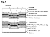
- Figure 1 shows a structure of an HD-DVD (one-sided, dual-layer rewritable disk) which has been developed in recent years, as an example of the optical recording medium.
- the optical recording medium has a multilayer structure comprising the reflection film in addition to a recording layer which plays a predominant role of a function of the optical recording medium, a protective layer and a thermal diffusion layer.
- silver has a problem of undergoing a color change into black through being corroded to decrease its reflectance, because of being inferior in corrosion resistance.
- the factor of causing corrosion in a reflection film is, for instance, an organic dye applied in a recording layer of an optical recording medium, though it varies depending on an applied medium and device. Then, the reflection film shows lower reflectance after having been corroded by the organic dye for a long period of use.
- the reflection film in a display device may cause corrosion due to the atmospheric moisture. For this reason, a thin film made from a silver alloy has been developed which contains various elements in a silver matrix, so as to solve the problem of the corrosion resistance of silver.
- Patent Document 1 discloses a silver alloy containing 0.5 to 10 atom% ruthenium and 0.1 to 10 atom% aluminum
- Patent Document 2 discloses a silver alloy containing 0.5 to 4.9 atom% palladium
- Patent Document 3 and Patent Document 4 disclose a silver alloy containing Ca, V and Nb, and the like.
- a thin film composed of the above described silver alloy shows a certain effect of having improved corrosion resistance. Then, a problem of the corrosion should have been solved, but an optical recording medium using a thin film formed from the silver alloy still can not completely inhibit a recording error caused by degradation of the reflection film. On the other hand, a material more excellent in reflectance-keeping characteristics than ever has been required along with requirement to a further improvement of a recording speed and recording density toward future.
- the present invention is directed at providing a thin film that is applied to a reflection film and a semi-transparent reflection film, which compose an optical recording medium, a display and the like, and that can function without decreasing its reflectivity even after a long period of use; and a production method therefor.
- the present inventors made an extensive research on a mechanism how a silver thin film degrades its reflecting characteristics, and found that the factor of the degradation is not only in simple corrosion (blackening) but also in a phenomenon that silver atoms migrate while the thin film is heated.
- the phenomenon of the migration of the silver atoms is a phenomenon that silver atoms composing a flat thin film right after having been formed migrate toward an energetically stable state through being driven by a given environmental condition. At this time, the silver atoms migrate not only in a planar direction but also in a three-dimensional direction in many cases, and as a result, cohere into a polygonal shape close to a sphere.
- an optical recording medium employing such a thin film for a reflection film reflects less light toward a sensor of an optical recording device in a sensor axis direction, and consequently causes an error in the recording medium.
- the above described phenomenon of the migration and cohesion of silver atoms differs from a corrosion phenomenon, is not sufficiently solved by only using an alloy, which has been a conventional measure, and is preferably solved by preventing the migration of the silver atoms composing the thin film.
- the present inventors studied a technique for inhibiting silver atoms from migrating in a thin film, found that it is preferable for inhibiting the silver atoms from migrating to disperse a silver compound phase which is not silver (pure silver) in a silver matrix, and becomes possible to form a silver thin film superior in reflectance-keeping characteristics, and arrived at the present invention.
- the present invention provides a thin film for a reflection film or a semi-transparent reflection film, which includes at least one silver compound phase of nitride, oxide, complex oxide, nitroxide, carbide, sulfide, chloride, silicide, fluoride, boride, hydride, phosphide, selenide and telluride of silver, dispersed in a matrix formed of silver.
- a silver compound composing a silver compound phase includes nitride, oxide, carbide, sulfide, chloride, silicide, fluoride, boride, phosphide, selenide and telluride.
- silver compound phase Specific examples of a silver compound phase are shown in Table 1. These silver compounds include a compound in a stoichiometrically nonequilibrium state, in addition to compounds having a composition in a stoichiometrically equilibrium state as shown in Table 1, which makes the compounds stably exist; and accordingly, for instance, AgN (silver nitride) includes Ag x N 1-x (O ⁇ x ⁇ 1).
- the silver compound phase is preferably contained in an amount of 0.001 to 2.5 wt.%.
- the silver compound in an amount of 0.001 wt.% or more is necessary for sufficiently inhibiting the migration of silver atoms.
- the upper limit is set at 2.5 wt.% because the silver compound contained above the upper limit imparts an insufficient initial reflectivity to the thin film.
- the content of the silver compound phase is preferably 0.001 to 1.0 wt.%, and further preferably is 0.001 to 0.5 wt.%. As the content of the silver compound increases, the effect of inhibiting the deterioration in reflectivity increases but the reflectivity tends to deteriorate. It is preferable to control the content of the silver compound depending on an application field within the above described range. In the above description, the content of the silver compound phase is based on the total weight of the thin film (the total weight of the matrix and the silver compound phase).
- a silver compound phase is preferably in a particulate form composed of many molecules of the compound, but is not always limited to this form.
- the silver compound phase may be formed of molecules of at least one compound.
- the size of the silver compound phase is preferably controlled into 1/10 or less of a thickness of a thin film. For instance, when the thickness of the thin film is set at 1,000 ⁇ , the silver compound phase preferably has a size of 100 ⁇ or smaller, and when the thickness of the thin film is set at 120 ⁇ , the dispersing silver compound phase preferably has a size of 12 A or smaller.
- a reflection film according to the present invention has preferably a thickness of 120 to 1,200 ⁇ when applied to an optical recording medium, a display and the like.
- it is preferably to apply a sputtering technique as a production method.
- the technique includes two directions which will be described below.
- a first technique is a method of using a target having a structure and a composition similar to a thin film to be produced, specifically, is a method of using a target prepared by dispersing at least one silver compound phase of nitride, oxide, complex oxide, nitroxide, carbide, sulfide, chloride, silicide, fluoride, boride, hydride, phosphide, selenide and telluride of silver, in a matrix formed of silver.
- the method can produce the thin film with the use of one sheet of target, accordingly can produce the thin film by a sputtering technique with a form of arranging the target so as to face a substrate, which is ordinarily employed when producing a reflection film, and consequently produce the thin film with adequate productivity.
- a sputtering technique with a form of arranging the target so as to face a substrate, which is ordinarily employed when producing a reflection film, and consequently produce the thin film with adequate productivity.
- a first form is an internally chemically-combined type target.
- the internally chemically-combined type target is prepared by heat-treating a raw material made from silver (pure silver) in an atmosphere of high-pressure oxygen gas, nitrogen gas or the like to chemically combine the interior partially with oxygen or nitrogen or the like into the oxide, the nitride or the like.
- the target in the form is useful for producing a thin film containing the oxide or the nitride as a silver compound phase.
- the raw material described in the above may have a tabular shape close to the shape of the target, or may be prepared by employing a granular material, chemically combining the interior with other elements for the raw material, and then compression-molding the resultant granular material.
- a second form to be used is a sintered target.
- the sintered target is prepared by mixing a powder of silver (pure silver) with a powder of a silver compound depending on a composition to be aimed, compressing and molding the mixed powder, and sintering the compact.
- the sintered target is useful for producing a thin film which is hardly produced by the above described internally chemically-combined type target, and is preferable for producing such a thin film as to disperse silver carbide, silver boride and silver silicide as a silver compound in the matrix.
- a third form is an embedded type target.
- the embedded type target is prepared by embedding a small piece (with a cylindrical shape and a spherical shape though the shape is not limited) of a silver compound which is to be a dispersing particle, into a region to be consumed by sputtering in a target made from pure silver.
- the above described internally chemically-combined type target and sintered target have a composition and a structure microscopically close to those of a thin film to be produced, as is shown in Fig. 2(a) , whereas this target has those macroscopically close to the thin film to be produced, as is shown in Fig. 2(b) .
- the composition of the thin film to be produced can be controlled by changing a diameter of the small piece of the silver compound to be embedded, positions of the small pieces to be arranged, the number of the pieces and a sputtering rate.
- a content of a silver compound phase is preferably controlled so as to have the same composition as a thin film to be produced.
- the content of the silver compound is preferably 0.001 to 2.5 wt.%, more preferably is 0.001 to 1.0 wt.%, and further preferably is 0.001 to 0.5 wt.%.
- the size of the silver compound phase in these targets is not limited in particular, and may be the same molecular level as in the case of the thin film to be produced, or may be a millimeter order as in the case of the embedded type target. This is because whatever the size of the silver compound phase, a compound is sputtered in a molecule unit when being sputtered, and the formed thin film acquires the composition to be aimed.
- This second direction is to improve a sputtering condition.
- an easily-available pure silver target can be used and the specially integrated target is not needed.
- the method is useful when it is difficult to prepare a special target such as an internally chemically-combined type target as was described above.
- there are further two applicable techniques which will be described below.
- a first technique is a co-sputtering technique with the use of a plurality of targets.
- the technique is a method of simultaneously sputtering a plurality of targets made from a compound having the same composition as a phase composing a thin film, and made from the same metal.
- the thin film having silver oxides dispersed in silver can be produced by using two targets of a pure silver target and a silver oxide (AgO) target, placing them together in a chamber, and simultaneously sputtering the two targets.
- the reactive sputtering is a technique of adding a reactive gas such as oxygen and nitrogen into an atmosphere for sputtering, sputtering the target, and forming a thin film while oxidizing or nitriding one part of a particle sputtered from a target.
- the reactive sputtering technique is a useful method when a silver compound to be dispersed in the thin film is expensive, is not available or is difficult to be chemically prepared.
- the reactive sputtering technique may be singly used, but may be used in combination with another technique.
- the above described special integral target specifically, using an internally chemically-combined target, a sintered target and an embedded type target
- it is possible to increase a content of a silver compound in the thin film by introducing a reactive gas into an atmosphere in a sputtering apparatus.
- three targets were produced which were an internally chemically-combined type target, a sintered type target and an embedded type target. Then, a thin film was produced not only by using these targets, but also by using a co-sputtering technique and a reactive sputtering technique.
- a internally chemically-combined type target was prepared by the steps of: preparing 2.5 kg of a granular raw material of pure silver with a particle diameter of 0.5 to 1.0 mm; charging it into a high-pressure reactive pot; replacing the air inside the pot sufficiently with nitrogen gas; increasing a pressure and a temperature respectively to a nitrogen gas pressure of 1.0 MPa and 850°C; and keeping the pot in the state for 6 hours for subjecting pure silver to internal nitriding; then, slowly cooling the internally nitrided silver grains; taking them out; charging them into a die; high-pressure-extruding them at 750°C into an integrated compact; forging the compact; rolling the forged compact into a plate (with size of 160 mm ⁇ 160 mm ⁇ 6 mm); and the cutting the plate into a sputtering target having a standard size (with a diameter of 152 mm (6 inches) and a thickness of 5 mm).
- the target had a composition of Ag/0.001 wt.% AgN
- the target of the sample No. 2 was produced by setting a retaining period of time for subjecting the pure silver to internal nitriding, at 15 hours; and the target of the sample No. 6 was produced by the steps of replacing the air inside the high-pressure reactive pot with oxygen gas (into gas pressure of 0.4 MPa) and reacting pure silver grains with oxygen at 850°C for 10 hours.
- a sintered type target was produced by the steps of: preparing a powder of pure silver and a powder of silver nitride both with particle sizes of 75 to 100 ⁇ m; weighing the powders so as to form an aimed composition; sufficiently mixing them; then charging the mixture into a die made from carbon; pressing the mixture to form a green compact; then sintering the green compact in a vacuum sintering furnace at 600°C for 24 hours to form a sintered compact; forging and rolling the compact into a plate for further improving a densed degree; and then cutting the plate into a sputtering target with the same standard size as described previously.
- the target had a composition of Ag/0.5 wt.% AgN.
- the target corresponds to the sample No. 3 which will be described later.
- An embedded type target was produced by the steps of: preparing a disc with a standard size (with a diameter of 152 mm (6 inches) and a thickness of 5 mm) made from pure silver; perforating three round holes with a diameter of 1.05 mm at equal spaces so as to form a circle with a diameter of 80 mm; inserting round bars made from silver oxide with a diameter of 1.0 mm and a length of 5 mm into the round holes; and caulking perimeters of the round bars so that the round bars will not drop off and could be fixed.
- the target had a composition of Ag/1.0 wt.% Ag 2 O. The target corresponds to the sample No. 10 which will be described later.
- a target corresponding to a composition equivalent to Ag/0.1 wt.% AgC (sample No. 12) was produced, in addition to the above described target.
- six round rods with a diameter of 0.50 mm made from silver carbide were inserted and fixed in round holes with a diameter of 0.55 mm.
- a thin film was produced by using the above described various targets, and by employing a co-sputtering technique and a reactive sputtering technique.
- the thin film was formed on a polycarbonate substrate for DVD.
- the substrate (with a diameter of 120 mm and a sheet thickness of 0.6 mm) was produced through an injection molding machine provided with a stamper, in which a pre-format pattern was formed.
- the reflection film was formed into a film thickness of 120 ⁇ with each method.
- Two targets of a pure silver target and an Ag-0.1 wt.% AgC target corresponding to the above described sample No. 12 were set at two positions among three-divided positions which are located on a concentric circle having a radius of 160 mm from the center axis of a sputtering apparatus. Then, the inside of the apparatus was evacuated, and Ar gas was introduced until the pressure reached 5.0 ⁇ 10 -1 Pa.
- the thin film was formed on a substrate by the steps of mounting the substrate on the center of a turntable; rotating the turntable at 10 rpm; and applying sputtering electric powers of a direct current of 0.99 kW to the pure silver target and a direct current of 0.01 kW to the Ag-0.1 wt.% AgC target to sputter the targets for eight seconds.
- Thus produced thin film had a composition of Ag/0.001 wt.% AgC.
- the composition corresponds to a sample No. 11 which will be described later.
- the thickness of the above produced film was distributed within ⁇ 10%.
- the composition of the thin film can be adjusted by changing the composition of a target used in combination with the pure silver target.
- the thin films of the samples No. 9 and 13 to 31 were produced by the method in the present embodiment as well.
- a pure silver target was set in a sputtering apparatus, the apparatus was evacuated, and Ar gas was introduced till the pressure reached 5.0 ⁇ 10 -1 Pa. Subsequently, nitrogen gas was introduced as a reactive gas. A partial pressure of the nitrogen gas was controlled into 5.0 ⁇ 10 -2 Pa. Then, a thin film was produced on a substrate by placing the substrate right under the target in a resting state, and sputtering the target at a direct current of 0.4 kW for eight seconds. Thus produced thin film had a composition of Ag/1.0 wt.% AgN. The composition corresponds to a sample No. 4 which will be described later. By employing the reactive sputtering technique, the composition of the thin film can be adjusted by increasing or decreasing the partial pressure of the reactive gas.
- the thin films of the samples No. 5, 7 and 8 were produced by the method in the present embodiment as well.
- a thin film was evaluated by evaluating characteristics of a DVD medium which was prepared by forming a thin film on a polycarbonate substrate in the above described manner.
- the evaluation was conducted by the steps of: measuring a jitter value, a PI error, a PO failure and a reflectance of the DVD medium in an initial state after having been prepared with the use of an optical disc evaluation instrument (optical disc evaluation instrument ODU-1000 made by Pulstec Industrial Co., Ltd.); confirming whether they were within a range of DVD standards; subsequently subjecting the DVD medium to an accelerating environmental test of exposing the DVD medium into an environment of a temperature of 80°C and a relative humidity of 85% for 500 hours; and measuring the respective values of the DVD medium after having been subjected to the accelerating environmental test by using the evaluation instrument.
- optical disc evaluation instrument ODU-1000 made by Pulstec Industrial Co., Ltd.
- a recording medium provided with a reflection film having a silver compound phase dispersed therein according to the present invention showed less occurrences of a PI error and a PO failure and further a lower decreasing rate of a reflectance than a DVD medium provided with a reflection film formed from pure silver.
- the DVD medium provided with the reflection film formed from pure silver was not recognized by a recording device after a humidification test, and became unusable.
- a thin film according to the present invention makes the reflectance little lowered even after a long period of use, and can prolong the life of various devices which use the thin film as a reflection film, such as an optical recording medium and a display.
- the reflection film according to the present invention has also reflectance-keeping characteristics which are little affected by a wavelength of incident light.
- the wavelength of light for a light source for recording is being shortened such as in the development of an HD-DVD using a blue laser beam, in a field of an optical recording medium.
- the present invention can cope with such a technology.
- the thin film according to the present invention provides merits of reducing the number of errors and extending the life, when applied to the optical recording medium, for instance.
- a reflection film has only to have a function of reflecting light, and includes a film having optical transparency. Accordingly, the reflection film according to the present invention can be also applied to a semi-reflective/semi-transparent film used in an optical recording medium.
Landscapes
- Chemical & Material Sciences (AREA)
- Engineering & Computer Science (AREA)
- Physics & Mathematics (AREA)
- Chemical Kinetics & Catalysis (AREA)
- Materials Engineering (AREA)
- Mechanical Engineering (AREA)
- Metallurgy (AREA)
- Organic Chemistry (AREA)
- General Physics & Mathematics (AREA)
- Optics & Photonics (AREA)
- Manufacturing & Machinery (AREA)
- Inorganic Chemistry (AREA)
- Manufacturing Optical Record Carriers (AREA)
- Physical Vapour Deposition (AREA)
- Optical Elements Other Than Lenses (AREA)
- Optical Record Carriers And Manufacture Thereof (AREA)
Abstract
The present invention provides a thin film for a reflection film or for a semi-transparent reflection film, which has at least one silver compound phase of nitride, oxide, complex oxide, nitroxide, carbide, sulfide, chloride, silicide, fluoride, boride, hydride, phosphide, selenide and telluride of silver, dispersed in a matrix formed of silver. The thin film according to the present invention keeps its reflectance without significant loss even after a long period of use, and can prolong the life of various devices which comprises the thin film as a reflection film, such as an optical recording medium and a display. The thin film can be also applied to a semi-reflective/semi-transparent film used in the optical recording medium.
Description
- The present invention relates to a thin film useful as a reflection film or a semi-transparent reflection film used in an optical recording medium, a display and the like. The present invention particularly relates to a thin film which shows reflectance that does not decrease even after having been used for a long period of time, and the optical recording medium having the thin film as the reflection film or the semi-transparent reflection film.
- An optical recording medium, such as a CD-R/RW, a DVD-R/RW/RAM and a Blue-Ray disk, and a display device, such as a liquid crystal display and an organic luminescent display have at least one layer of a reflection film formed therein. For instance,
Figure 1 shows a structure of an HD-DVD (one-sided, dual-layer rewritable disk) which has been developed in recent years, as an example of the optical recording medium. As shown in the example, the optical recording medium has a multilayer structure comprising the reflection film in addition to a recording layer which plays a predominant role of a function of the optical recording medium, a protective layer and a thermal diffusion layer. - Many conventional reflection films are made from silver. This is because silver has a high reflectivity and is less expensive than gold having the high reflectivity similarly to silver. Silver also has excellent optical transparency when the film thickness is appropriately adjusted, accordingly can be possibly used as a semi-transparent reflection film, and from this fact, has been applied to an optical recording medium being developed now (cf.
Fig. 1 ). - On the other hand, silver has a problem of undergoing a color change into black through being corroded to decrease its reflectance, because of being inferior in corrosion resistance. The factor of causing corrosion in a reflection film is, for instance, an organic dye applied in a recording layer of an optical recording medium, though it varies depending on an applied medium and device. Then, the reflection film shows lower reflectance after having been corroded by the organic dye for a long period of use. In addition, the reflection film in a display device may cause corrosion due to the atmospheric moisture. For this reason, a thin film made from a silver alloy has been developed which contains various elements in a silver matrix, so as to solve the problem of the corrosion resistance of silver.
- For instance,
Patent Document 1 discloses a silver alloy containing 0.5 to 10 atom% ruthenium and 0.1 to 10 atom% aluminum, and Patent Document 2 discloses a silver alloy containing 0.5 to 4.9 atom% palladium. In addition, Patent Document 3 and Patent Document 4 disclose a silver alloy containing Ca, V and Nb, and the like. - Patent Document 1: Japanese Patent Laid-Open No.
11-134715 - Patent Document 2: Japanese Patent Laid-Open No.
2000-109943 - Patent Document 3: Japanese Patent Laid-Open No.
6-243509 - Patent Document 4: Japanese Patent Laid-Open No.
2003-6926 - A thin film composed of the above described silver alloy shows a certain effect of having improved corrosion resistance. Then, a problem of the corrosion should have been solved, but an optical recording medium using a thin film formed from the silver alloy still can not completely inhibit a recording error caused by degradation of the reflection film. On the other hand, a material more excellent in reflectance-keeping characteristics than ever has been required along with requirement to a further improvement of a recording speed and recording density toward future.
- On the basis of the background, the present invention is directed at providing a thin film that is applied to a reflection film and a semi-transparent reflection film, which compose an optical recording medium, a display and the like, and that can function without decreasing its reflectivity even after a long period of use; and a production method therefor.
- In order to solve such a problem, the present inventors made an extensive research on a mechanism how a silver thin film degrades its reflecting characteristics, and found that the factor of the degradation is not only in simple corrosion (blackening) but also in a phenomenon that silver atoms migrate while the thin film is heated. The phenomenon of the migration of the silver atoms is a phenomenon that silver atoms composing a flat thin film right after having been formed migrate toward an energetically stable state through being driven by a given environmental condition. At this time, the silver atoms migrate not only in a planar direction but also in a three-dimensional direction in many cases, and as a result, cohere into a polygonal shape close to a sphere. When such a three-dimensionally cohered body is formed in the thin film, a laser beam incident on the thin film is reflected toward irregular directions with respect to an incident axis and consequently toward many directions. Accordingly, an optical recording medium employing such a thin film for a reflection film reflects less light toward a sensor of an optical recording device in a sensor axis direction, and consequently causes an error in the recording medium.
- The above described phenomenon of the migration and cohesion of silver atoms differs from a corrosion phenomenon, is not sufficiently solved by only using an alloy, which has been a conventional measure, and is preferably solved by preventing the migration of the silver atoms composing the thin film.
- Then, the present inventors studied a technique for inhibiting silver atoms from migrating in a thin film, found that it is preferable for inhibiting the silver atoms from migrating to disperse a silver compound phase which is not silver (pure silver) in a silver matrix, and becomes possible to form a silver thin film superior in reflectance-keeping characteristics, and arrived at the present invention.
- Specifically, the present invention provides a thin film for a reflection film or a semi-transparent reflection film, which includes at least one silver compound phase of nitride, oxide, complex oxide, nitroxide, carbide, sulfide, chloride, silicide, fluoride, boride, hydride, phosphide, selenide and telluride of silver, dispersed in a matrix formed of silver.
- In the present invention, a silver compound composing a silver compound phase includes nitride, oxide, carbide, sulfide, chloride, silicide, fluoride, boride, phosphide, selenide and telluride. By dispersing the phase consisting of these silver compounds in a silver matrix, it becomes possible to inhibit the migration of silver atoms composing the matrix, to maintain the flatness of a thin film, and thereby to inhibit the reflectance from lowering even when the thin film has received heat.
- Specific examples of a silver compound phase are shown in Table 1. These silver compounds include a compound in a stoichiometrically nonequilibrium state, in addition to compounds having a composition in a stoichiometrically equilibrium state as shown in Table 1, which makes the compounds stably exist; and accordingly, for instance, AgN (silver nitride) includes AgxN1-x (O <x <1).
[Table 1] Nitride AgN (Ag1-xNx) Oxide Ag2O,AgO (Ag1-xOx) Carbide AgC (Ag1-xCx) Sulfide Ag2S (Ag2-xSx) Fluoride AgF (Ag1-xFx) Boride AgB (Ag1-xBx) Silicide AgSi (Ag1-xSix) Chloride AgCl (Ag1-xClx) Phosphide AgP (Ag1-xPx) Selenide Ag2Se (Ag2-xSex) Telluride Ag2Te (Ag2-xTex) Ag2MO4Ag2WO4 Complex oxide AgVO3Ag2CrO4 Ag4P2O7Ag3PO4 - The silver compound phase is preferably contained in an amount of 0.001 to 2.5 wt.%. The silver compound in an amount of 0.001 wt.% or more is necessary for sufficiently inhibiting the migration of silver atoms. In addition, the upper limit is set at 2.5 wt.% because the silver compound contained above the upper limit imparts an insufficient initial reflectivity to the thin film. Accordingly, the content of the silver compound phase is preferably 0.001 to 1.0 wt.%, and further preferably is 0.001 to 0.5 wt.%. As the content of the silver compound increases, the effect of inhibiting the deterioration in reflectivity increases but the reflectivity tends to deteriorate. It is preferable to control the content of the silver compound depending on an application field within the above described range. In the above description, the content of the silver compound phase is based on the total weight of the thin film (the total weight of the matrix and the silver compound phase).
- A silver compound phase is preferably in a particulate form composed of many molecules of the compound, but is not always limited to this form. Specifically, the silver compound phase may be formed of molecules of at least one compound. The size of the silver compound phase is preferably controlled into 1/10 or less of a thickness of a thin film. For instance, when the thickness of the thin film is set at 1,000 Å, the silver compound phase preferably has a size of 100 Å or smaller, and when the thickness of the thin film is set at 120 Å, the dispersing silver compound phase preferably has a size of 12 A or smaller.
- In the next place, a method for producing a thin film according to the present invention will be described. A reflection film according to the present invention has preferably a thickness of 120 to 1,200 Å when applied to an optical recording medium, a display and the like. When producing such a thin film, it is preferably to apply a sputtering technique as a production method. When applying the sputtering technique for producing the thin film containing a silver compound phase, the technique includes two directions which will be described below.
- A first technique is a method of using a target having a structure and a composition similar to a thin film to be produced, specifically, is a method of using a target prepared by dispersing at least one silver compound phase of nitride, oxide, complex oxide, nitroxide, carbide, sulfide, chloride, silicide, fluoride, boride, hydride, phosphide, selenide and telluride of silver, in a matrix formed of silver. The method can produce the thin film with the use of one sheet of target, accordingly can produce the thin film by a sputtering technique with a form of arranging the target so as to face a substrate, which is ordinarily employed when producing a reflection film, and consequently produce the thin film with adequate productivity. Here, there are further three forms in the sputtering target for producing the thin film according to the present invention, as will be described below.
- A first form is an internally chemically-combined type target. The internally chemically-combined type target is prepared by heat-treating a raw material made from silver (pure silver) in an atmosphere of high-pressure oxygen gas, nitrogen gas or the like to chemically combine the interior partially with oxygen or nitrogen or the like into the oxide, the nitride or the like. The target in the form is useful for producing a thin film containing the oxide or the nitride as a silver compound phase. The raw material described in the above may have a tabular shape close to the shape of the target, or may be prepared by employing a granular material, chemically combining the interior with other elements for the raw material, and then compression-molding the resultant granular material.
- A second form to be used is a sintered target. The sintered target is prepared by mixing a powder of silver (pure silver) with a powder of a silver compound depending on a composition to be aimed, compressing and molding the mixed powder, and sintering the compact. The sintered target is useful for producing a thin film which is hardly produced by the above described internally chemically-combined type target, and is preferable for producing such a thin film as to disperse silver carbide, silver boride and silver silicide as a silver compound in the matrix.
- A third form is an embedded type target. The embedded type target is prepared by embedding a small piece (with a cylindrical shape and a spherical shape though the shape is not limited) of a silver compound which is to be a dispersing particle, into a region to be consumed by sputtering in a target made from pure silver. The above described internally chemically-combined type target and sintered target have a composition and a structure microscopically close to those of a thin film to be produced, as is shown in
Fig. 2(a) , whereas this target has those macroscopically close to the thin film to be produced, as is shown inFig. 2(b) . When the target is used, the composition of the thin film to be produced can be controlled by changing a diameter of the small piece of the silver compound to be embedded, positions of the small pieces to be arranged, the number of the pieces and a sputtering rate. - In the above described three types of targets, a content of a silver compound phase is preferably controlled so as to have the same composition as a thin film to be produced. Accordingly, the content of the silver compound is preferably 0.001 to 2.5 wt.%, more preferably is 0.001 to 1.0 wt.%, and further preferably is 0.001 to 0.5 wt.%. In addition, the size of the silver compound phase in these targets is not limited in particular, and may be the same molecular level as in the case of the thin film to be produced, or may be a millimeter order as in the case of the embedded type target. This is because whatever the size of the silver compound phase, a compound is sputtered in a molecule unit when being sputtered, and the formed thin film acquires the composition to be aimed.
- On the other hand, it is possible to produce a thin film according to the present invention even without using such one sheet of an integrated target as described above. This second direction is to improve a sputtering condition. In this method, an easily-available pure silver target can be used and the specially integrated target is not needed. The method is useful when it is difficult to prepare a special target such as an internally chemically-combined type target as was described above. In the second direction, there are further two applicable techniques which will be described below.
- A first technique is a co-sputtering technique with the use of a plurality of targets. The technique is a method of simultaneously sputtering a plurality of targets made from a compound having the same composition as a phase composing a thin film, and made from the same metal. For instance, the thin film having silver oxides dispersed in silver can be produced by using two targets of a pure silver target and a silver oxide (AgO) target, placing them together in a chamber, and simultaneously sputtering the two targets.
- In addition, it is particularly useful in a second direction for improving a sputtering condition to employ a reactive sputtering technique. The reactive sputtering is a technique of adding a reactive gas such as oxygen and nitrogen into an atmosphere for sputtering, sputtering the target, and forming a thin film while oxidizing or nitriding one part of a particle sputtered from a target. The reactive sputtering technique is a useful method when a silver compound to be dispersed in the thin film is expensive, is not available or is difficult to be chemically prepared.
- The reactive sputtering technique may be singly used, but may be used in combination with another technique. For instance, when using the above described special integral target, specifically, using an internally chemically-combined target, a sintered target and an embedded type target, and when it is anticipated that an amount of a dispersed silver compound in a thin film will be insufficient only by independently using the targets, it is possible to increase a content of a silver compound in the thin film by introducing a reactive gas into an atmosphere in a sputtering apparatus. In addition, when producing a thin film by using a co-sputtering technique as well, it is possible to adjust the amount of the silver compound by using the reactive sputtering technique in combination with the co-sputtering technique.
-
-
Fig. 1 illustrates an example of a structure for an HD-DVD; and -
Fig. 2 illustrates specific examples of a sputtering target for producing a reflection film or a semi-transparent reflection film according to the present invention. - In the present embodiment, at first, three targets were produced which were an internally chemically-combined type target, a sintered type target and an embedded type target. Then, a thin film was produced not only by using these targets, but also by using a co-sputtering technique and a reactive sputtering technique.
- A internally chemically-combined type target was prepared by the steps of: preparing 2.5 kg of a granular raw material of pure silver with a particle diameter of 0.5 to 1.0 mm; charging it into a high-pressure reactive pot; replacing the air inside the pot sufficiently with nitrogen gas; increasing a pressure and a temperature respectively to a nitrogen gas pressure of 1.0 MPa and 850°C; and keeping the pot in the state for 6 hours for subjecting pure silver to internal nitriding; then, slowly cooling the internally nitrided silver grains; taking them out; charging them into a die; high-pressure-extruding them at 750°C into an integrated compact; forging the compact; rolling the forged compact into a plate (with size of 160 mm × 160 mm × 6 mm); and the cutting the plate into a sputtering target having a standard size (with a diameter of 152 mm (6 inches) and a thickness of 5 mm). The target had a composition of Ag/0.001 wt.% AgN in which silver nitride of a compound phase was dispersed in a silver matrix. The target corresponds to the sample No. 1 which will be described later.
- In addition to the above described target, other internally chemically-combined type targets were prepared which had compositions of Ag/0.01 wt.% AgN (sample No. 2) and Ag/0.001 wt.% Ag2O (sample No. 6). As for these targets, the target of the sample No. 2 was produced by setting a retaining period of time for subjecting the pure silver to internal nitriding, at 15 hours; and the target of the sample No. 6 was produced by the steps of replacing the air inside the high-pressure reactive pot with oxygen gas (into gas pressure of 0.4 MPa) and reacting pure silver grains with oxygen at 850°C for 10 hours.
- A sintered type target was produced by the steps of: preparing a powder of pure silver and a powder of silver nitride both with particle sizes of 75 to 100 µm; weighing the powders so as to form an aimed composition; sufficiently mixing them; then charging the mixture into a die made from carbon; pressing the mixture to form a green compact; then sintering the green compact in a vacuum sintering furnace at 600°C for 24 hours to form a sintered compact; forging and rolling the compact into a plate for further improving a densed degree; and then cutting the plate into a sputtering target with the same standard size as described previously. The target had a composition of Ag/0.5 wt.% AgN. The target corresponds to the sample No. 3 which will be described later.
- An embedded type target was produced by the steps of: preparing a disc with a standard size (with a diameter of 152 mm (6 inches) and a thickness of 5 mm) made from pure silver; perforating three round holes with a diameter of 1.05 mm at equal spaces so as to form a circle with a diameter of 80 mm; inserting round bars made from silver oxide with a diameter of 1.0 mm and a length of 5 mm into the round holes; and caulking perimeters of the round bars so that the round bars will not drop off and could be fixed. The target had a composition of Ag/1.0 wt.% Ag2O. The target corresponds to the sample No. 10 which will be described later.
- As for the embedded type target, a target corresponding to a composition equivalent to Ag/0.1 wt.% AgC (sample No. 12) was produced, in addition to the above described target. In the above target, six round rods with a diameter of 0.50 mm made from silver carbide were inserted and fixed in round holes with a diameter of 0.55 mm.
- A thin film was produced by using the above described various targets, and by employing a co-sputtering technique and a reactive sputtering technique. Here, the thin film was formed on a polycarbonate substrate for DVD. The substrate (with a diameter of 120 mm and a sheet thickness of 0.6 mm) was produced through an injection molding machine provided with a stamper, in which a pre-format pattern was formed. On the top face of the substrate, the reflection film was formed into a film thickness of 120 Å with each method.
- (i) A thin film was formed on a polycarbonate substrate by using each of three targets produced in the above described items (a) to (c). Setting each target in a sputtering chamber; and evacuating the chamber; introducing Ar gas till the pressure reaches 5.0×10⁻¹ Pa; placing a substrate right under the target in a resting state; and sputtering the target at a direct current of 0.4 kW for eight seconds. Then, the thickness of the resulting film was distributed within ±10%.
- (ii) Cosputtering
- Two targets of a pure silver target and an Ag-0.1 wt.% AgC target corresponding to the above described sample No. 12 were set at two positions among three-divided positions which are located on a concentric circle having a radius of 160 mm from the center axis of a sputtering apparatus. Then, the inside of the apparatus was evacuated, and Ar gas was introduced until the pressure reached 5.0×10⁻¹ Pa. Subsequently, the thin film was formed on a substrate by the steps of mounting the substrate on the center of a turntable; rotating the turntable at 10 rpm; and applying sputtering electric powers of a direct current of 0.99 kW to the pure silver target and a direct current of 0.01 kW to the Ag-0.1 wt.% AgC target to sputter the targets for eight seconds. Thus produced thin film had a composition of Ag/0.001 wt.% AgC. The composition corresponds to a sample No. 11 which will be described later. The thickness of the above produced film was distributed within ±10%. By employing the co-sputtering technique, the composition of the thin film can be adjusted by changing the composition of a target used in combination with the pure silver target. The thin films of the samples No. 9 and 13 to 31 were produced by the method in the present embodiment as well.
- A pure silver target was set in a sputtering apparatus, the apparatus was evacuated, and Ar gas was introduced till the pressure reached 5.0×10⁻¹ Pa. Subsequently, nitrogen gas was introduced as a reactive gas. A partial pressure of the nitrogen gas was controlled into 5.0×10⁻² Pa. Then, a thin film was produced on a substrate by placing the substrate right under the target in a resting state, and sputtering the target at a direct current of 0.4 kW for eight seconds. Thus produced thin film had a composition of Ag/1.0 wt.% AgN. The composition corresponds to a sample No. 4 which will be described later. By employing the reactive sputtering technique, the composition of the thin film can be adjusted by increasing or decreasing the partial pressure of the reactive gas. The thin films of the samples No. 5, 7 and 8 were produced by the method in the present embodiment as well.
- A thin film was evaluated by evaluating characteristics of a DVD medium which was prepared by forming a thin film on a polycarbonate substrate in the above described manner. The evaluation was conducted by the steps of: measuring a jitter value, a PI error, a PO failure and a reflectance of the DVD medium in an initial state after having been prepared with the use of an optical disc evaluation instrument (optical disc evaluation instrument ODU-1000 made by Pulstec Industrial Co., Ltd.); confirming whether they were within a range of DVD standards; subsequently subjecting the DVD medium to an accelerating environmental test of exposing the DVD medium into an environment of a temperature of 80°C and a relative humidity of 85% for 500 hours; and measuring the respective values of the DVD medium after having been subjected to the accelerating environmental test by using the evaluation instrument. The results are shown in Table 2. The table also shows the result of a similar test on a DVD medium having a pure silver film formed thereon as a reflection film.
[Table 2] Sample No. Sample composition (wt.%) Method for producing thin film*1 PI error PO failure Jitter (%) Reflectance (%) Initial stage After humidifi- cation Initial stage After humidification Initial stage After humidification Initial stage After humidification 1 Ag/0.001AgN a 18.2 1176.6 0.0 6.3 6.3 21.3 56.3 52.2 2 Ag/0.01AgN a 43.6 1097.4 0.0 6.0 7.8 20.3 55.7 53.1 3 Ag/0.5AgN b 23.3 932.3 0.0 5.2 7.5 17.3 54.2 51.8 4 Ag/1.0AgN e 33.3 698.9 0.0 3.7 7.4 14.3 53.4 52.3 5 Ag/2.5AgN e 21.3 426.5 0.0 2.5 7.7 10.3 52.7 52.3 6 Ag/0.001Ag2O a 22.1 1456.1 0.0 7.6 7.0 23.3 53.7 49.3 7 Ag/0.005Ag2O e 24.9 1243.2 0.0 7.1 7.6 22.3 53.1 48.8 8 Ag/0.05Ag2O e 22.5 1299.8 0.0 6.7 6.6 21.3 52.6 49.2 9 Ag/0.5Ag2O d 21.5 1013.8 0.0 5.3 7.8 19.3 51.8 48.9 10 Ag/1.0Ag2O c 17.0 857.9 0.0 4.6 6.4 17.3 50.3 49.6 11 Ag/0.001AgC d 19.6 989.4 0.0 5.5 6.8 19.3 54.6 53.4 12 Ag/0.1AgC c 18.6 819.2 0.0 4.6 7.1 16.3 53.8 53.3 13 Ag/0.001Ag2S d 14.3 1452.3 0.0 7.8 6.6 24.3 53.1 51.3 14 Ag/0.008Ag2S d 18.3 1156.0 0.0 6.8 7.8 22.3 47.5 46.5 15 Ag/0.001AgF d 18.2 1109.8 0.0 6.2 7.2 21.3 46.3 45.3 16 Ag/0.1AgB d 12.8 932.6 0.0 4.8 6.4 15.3 53.4 53.1 17 Ag/0.001AgSi d 25.1 1119.9 0.0 5.8 7.4 19.3 55.1 54.7 18 Ag/0.1AgSi d 24.8 872.6 0.0 4.9 7.3 18.3 54.3 53.6 19 Ag/0.001AgCl d 28.8 1376.2 0.0 7.5 6.8 23.3 53.9 52.4 20 Ag/0.02AgCl d 24.7 1366.5 0.0 7.2 6.9 24.3 52.1 50.8 21 Ag/0.08AgCl d 27.4 1144.0 0.0 6.5 7.6 22.3 49.7 48.6 22 Ag/0.001AgP d 12.6 1177.4 0.0 5.8 6.5 19.1 51.0 51.1 23 Ag/2.0AgP d 25.2 1164.0 0.0 6.0 7.5 20.2 48.5 48.5 24 Ag/0.001Ag2Se d 17.5 1270.5 0.0 6.6 7.5 21.3 51.6 50.4 25 Ag/0.5Ag2Se d 19.4 1126.6 0.0 6.1 7.6 19.3 46.9 46.2 26 Ag/0.001Ag2Te d 27.2 1178.4 0.0 6.8 6.3 23.3 52.1 50.5 27 Ag/1.0Ag2Te d 26.3 1142.8 0.0 5.9 6.4 20.3 45.7 45.2 28 Ag/1.0Ag2CrO4 d 44.2 1442.0 0.0 7.0 7.4 24.7 51.4 50.8 29 Ag/2.5Ag2MoO4 d 26.9 1350.5 0.0 7.3 6.8 24.1 48.3 46.4 30 Ag/2.5AgVO3 d 43.7 1295.0 0.0 7.0 6.4 20.9 49.1 49.2 31 Ag/2.5Ag2WO4 d 16.1 1396.8 0.0 7.2 6.9 23.2 48.9 48.0 Ag100.0 - 23.8 1664.0 0.0 8.0 6.5 27.0 57.0 51.5 *1 Methods for producing each thin film are described below.
a: having used internally chemically-combined type target
b: having used sintering type target
c: having used embedded type target
d: co-sputtering
e: reactive sputtering - As is understood from Table 2, it was confirmed that a recording medium provided with a reflection film having a silver compound phase dispersed therein according to the present invention showed less occurrences of a PI error and a PO failure and further a lower decreasing rate of a reflectance than a DVD medium provided with a reflection film formed from pure silver. For information, the DVD medium provided with the reflection film formed from pure silver was not recognized by a recording device after a humidification test, and became unusable.
- As described above, a thin film according to the present invention makes the reflectance little lowered even after a long period of use, and can prolong the life of various devices which use the thin film as a reflection film, such as an optical recording medium and a display. The reflection film according to the present invention has also reflectance-keeping characteristics which are little affected by a wavelength of incident light. In this regard, the wavelength of light for a light source for recording is being shortened such as in the development of an HD-DVD using a blue laser beam, in a field of an optical recording medium. The present invention can cope with such a technology. The thin film according to the present invention provides merits of reducing the number of errors and extending the life, when applied to the optical recording medium, for instance.
- In the present invention, a reflection film has only to have a function of reflecting light, and includes a film having optical transparency. Accordingly, the reflection film according to the present invention can be also applied to a semi-reflective/semi-transparent film used in an optical recording medium.
Claims (9)
- A thin film for a reflection film or for a semi-transparent reflection film, having at least one silver compound phase selected from the group consisting of nitride, oxide, complex oxide, nitroxide, carbide, sulfide, chloride, silicide, fluoride, boride, hydride, phosphide, selenide and telluride of silver, dispersed in a matrix formed of silver.
- The thin film according to claim 1, wherein the silver compound phase has a content of 0.001 to 2.5 wt.%.
- The thin film according to claim 1, wherein the silver compound phase has a content of 0.001 to 1.0 wt.%.
- The thin film according to claim 1, wherein the silver compound phase has a content of 0.001 to 0.5 wt.%.
- A sputtering target having at least one silver compound phase selected from the group consisting of nitride, oxide, complex oxide, nitroxide, carbide, sulfide, chloride, silicide, fluoride, boride, hydride, phosphide, selenide and telluride of silver, dispersed in a matrix formed of silver.
- The sputtering target according to claim 5, wherein the silver compound phase has a content of 0.001 to 2.5 wt.%.
- The sputtering target according to claim 5, wherein the silver compound phase has a content of 0.001 to 1.0 wt.%.
- The sputtering target according to claim 5, wherein the silver compound phase has a content of 0.001 to 0.5 wt.%.
- An optical recording medium comprising the thin film according to any one of claim 1 to claim 4, as a reflection film or a semi-transparent reflection film.
Applications Claiming Priority (1)
| Application Number | Priority Date | Filing Date | Title |
|---|---|---|---|
| PCT/JP2006/322930 WO2008059579A1 (en) | 2006-11-17 | 2006-11-17 | Thin film for reflective film or semi-transmitting reflective film, sputtering target, and optical recording medium |
Publications (1)
| Publication Number | Publication Date |
|---|---|
| EP2045630A1 true EP2045630A1 (en) | 2009-04-08 |
Family
ID=39401393
Family Applications (1)
| Application Number | Title | Priority Date | Filing Date |
|---|---|---|---|
| EP06832809A Withdrawn EP2045630A1 (en) | 2006-11-17 | 2006-11-17 | Thin film for reflective film or semi-transmitting reflective film, sputtering target, and optical recording medium |
Country Status (6)
| Country | Link |
|---|---|
| US (1) | US20100047507A1 (en) |
| EP (1) | EP2045630A1 (en) |
| JP (1) | JPWO2008059579A1 (en) |
| KR (1) | KR20090087051A (en) |
| CN (1) | CN101449185A (en) |
| WO (1) | WO2008059579A1 (en) |
Cited By (1)
| Publication number | Priority date | Publication date | Assignee | Title |
|---|---|---|---|---|
| EP3196334A4 (en) * | 2015-02-27 | 2018-04-11 | Mitsubishi Materials Corporation | Ag alloy sputtering target and ag alloy film manufacturing method |
Families Citing this family (2)
| Publication number | Priority date | Publication date | Assignee | Title |
|---|---|---|---|---|
| JP5264233B2 (en) * | 2008-03-24 | 2013-08-14 | 三菱電機株式会社 | Organic electroluminescent display |
| JP2021131312A (en) * | 2020-02-20 | 2021-09-09 | 株式会社ミツトヨ | scale |
Family Cites Families (9)
| Publication number | Priority date | Publication date | Assignee | Title |
|---|---|---|---|---|
| JPH06243509A (en) | 1993-02-19 | 1994-09-02 | Ricoh Co Ltd | Light reflection film and optical recording information medium using the film |
| JPH073440A (en) * | 1993-06-16 | 1995-01-06 | Asahi Glass Co Ltd | Electron gun, method for manufacturing substrate with thin film using the electron gun, and substrate with thin film |
| JPH11134715A (en) | 1997-10-28 | 1999-05-21 | Kao Corp | Optical recording medium |
| JP4007702B2 (en) | 1998-10-05 | 2007-11-14 | 株式会社フルヤ金属 | Sputtering target material for forming a thin film, a thin film formed using the same, and an optical recording medium |
| JP3904136B2 (en) * | 2000-04-12 | 2007-04-11 | 日立金属株式会社 | Composite vapor deposition material |
| TWI246075B (en) * | 2000-08-02 | 2005-12-21 | Mitsubishi Chem Corp | Optical recording medium and process for producing an optical recording medium |
| JP4047561B2 (en) * | 2000-08-02 | 2008-02-13 | 三菱化学メディア株式会社 | Optical information recording medium and method for manufacturing optical information recording medium |
| JP2003006926A (en) | 2001-06-19 | 2003-01-10 | Mitsubishi Materials Corp | Reflective film for optical recording media |
| JP2005243165A (en) * | 2004-02-27 | 2005-09-08 | Taiyo Yuden Co Ltd | Optical information recording medium |
-
2006
- 2006-11-17 EP EP06832809A patent/EP2045630A1/en not_active Withdrawn
- 2006-11-17 CN CNA2006800548043A patent/CN101449185A/en active Pending
- 2006-11-17 KR KR1020097011859A patent/KR20090087051A/en not_active Withdrawn
- 2006-11-17 WO PCT/JP2006/322930 patent/WO2008059579A1/en not_active Ceased
- 2006-11-17 US US11/915,394 patent/US20100047507A1/en not_active Abandoned
- 2006-11-17 JP JP2008544041A patent/JPWO2008059579A1/en active Pending
Non-Patent Citations (1)
| Title |
|---|
| See references of WO2008059579A1 * |
Cited By (2)
| Publication number | Priority date | Publication date | Assignee | Title |
|---|---|---|---|---|
| EP3196334A4 (en) * | 2015-02-27 | 2018-04-11 | Mitsubishi Materials Corporation | Ag alloy sputtering target and ag alloy film manufacturing method |
| US10577687B2 (en) | 2015-02-27 | 2020-03-03 | Mitsubishi Materials Corporation | Ag alloy sputtering target and Ag alloy film manufacturing method |
Also Published As
| Publication number | Publication date |
|---|---|
| JPWO2008059579A1 (en) | 2010-02-25 |
| WO2008059579A1 (en) | 2008-05-22 |
| CN101449185A (en) | 2009-06-03 |
| US20100047507A1 (en) | 2010-02-25 |
| KR20090087051A (en) | 2009-08-14 |
Similar Documents
| Publication | Publication Date | Title |
|---|---|---|
| CN1186772C (en) | Reflective layer or semi-transparent reflective layer for optical informatino recording media, optical information recording media and sputtering target for optical information recording media | |
| US7833604B2 (en) | Ag alloy reflective layer for optical information recording medium, optical information recording medium, and sputtering target for forming Ag alloy reflective layer for optical information recording medium | |
| EP1736558A1 (en) | Silver alloy for reflective film | |
| EP1523002B1 (en) | Information recording medium, method of manufacturing the same, and sputtering target | |
| EP2221394A1 (en) | Thin film mainly composed of titanium oxide, sintered sputtering target suitable for the production of thin film mainly composed of titanium oxide, and method for production of thin film mainly composed of titanium oxide | |
| EP2045631B1 (en) | Thin film for reflection film or semi-transparent reflection film, sputtering target and optical recording medium | |
| EP1734140A1 (en) | Silver alloy excelling in performance of reflectance maintenance | |
| EP2192585B1 (en) | Read-only optical information recording medium | |
| EP1734139A1 (en) | Silver alloy excelling in performance of reflectance maintenance | |
| EP2045630A1 (en) | Thin film for reflective film or semi-transmitting reflective film, sputtering target, and optical recording medium | |
| EP1985725A2 (en) | Sputtering target, optical information recording medium and process for producing the same | |
| EP2048524B1 (en) | Thin film for use as reflective film or semi-transmissive reflective film, sputtering target and optical recording medium | |
| US20120192763A1 (en) | Thin Film Comprising Titanium Oxide as Main Component and Sintered Compact Sputtering Target Comprising Titanium Oxide as Main Component | |
| EP2048664A1 (en) | Thin film for reflection film or semi-transparent reflection film, sputtering target, and optical recording medium | |
| CN101678693A (en) | Information recording medium, method for producing the same, and target | |
| TWI437563B (en) | And a reflective film-forming sputtering target for forming the optical information recording medium and the optical information recording medium | |
| JP2009217862A (en) | Information recording medium, target, and method for manufacturing information recording medium using the target | |
| EP1757712A1 (en) | Sputtering target, optical information recording medium and method for producing same | |
| JP2006028537A (en) | Protective film for optical disc, sputtering target for forming protective film, and method for producing the sputtering target |
Legal Events
| Date | Code | Title | Description |
|---|---|---|---|
| PUAI | Public reference made under article 153(3) epc to a published international application that has entered the european phase |
Free format text: ORIGINAL CODE: 0009012 |
|
| 17P | Request for examination filed |
Effective date: 20090120 |
|
| AK | Designated contracting states |
Kind code of ref document: A1 Designated state(s): AT BE BG CH CY CZ DE DK EE ES FI FR GB GR HU IE IS IT LI LT LU LV MC NL PL PT RO SE SI SK TR |
|
| AX | Request for extension of the european patent |
Extension state: AL BA HR MK RS |
|
| STAA | Information on the status of an ep patent application or granted ep patent |
Free format text: STATUS: THE APPLICATION HAS BEEN WITHDRAWN |
|
| 18W | Application withdrawn |
Effective date: 20091021 |