EP2045459B1 - A method of controlling fuel injection apparatus - Google Patents
A method of controlling fuel injection apparatus Download PDFInfo
- Publication number
- EP2045459B1 EP2045459B1 EP07019416A EP07019416A EP2045459B1 EP 2045459 B1 EP2045459 B1 EP 2045459B1 EP 07019416 A EP07019416 A EP 07019416A EP 07019416 A EP07019416 A EP 07019416A EP 2045459 B1 EP2045459 B1 EP 2045459B1
- Authority
- EP
- European Patent Office
- Prior art keywords
- power supply
- converter
- power
- output power
- event sequence
- Prior art date
- Legal status (The legal status is an assumption and is not a legal conclusion. Google has not performed a legal analysis and makes no representation as to the accuracy of the status listed.)
- Not-in-force
Links
- 238000002347 injection Methods 0.000 title claims abstract description 91
- 239000007924 injection Substances 0.000 title claims abstract description 91
- 238000000034 method Methods 0.000 title claims abstract description 48
- 239000000446 fuel Substances 0.000 title claims abstract description 46
- 238000012545 processing Methods 0.000 claims description 21
- 238000012544 monitoring process Methods 0.000 claims description 8
- 230000001419 dependent effect Effects 0.000 claims 1
- 239000003990 capacitor Substances 0.000 description 22
- 230000006870 function Effects 0.000 description 18
- 238000002485 combustion reaction Methods 0.000 description 6
- 230000008929 regeneration Effects 0.000 description 5
- 238000011069 regeneration method Methods 0.000 description 5
- 230000008569 process Effects 0.000 description 4
- 238000010586 diagram Methods 0.000 description 3
- 238000007599 discharging Methods 0.000 description 3
- 238000004364 calculation method Methods 0.000 description 2
- 238000004146 energy storage Methods 0.000 description 2
- 230000007704 transition Effects 0.000 description 2
- 230000009471 action Effects 0.000 description 1
- 230000009286 beneficial effect Effects 0.000 description 1
- 230000008901 benefit Effects 0.000 description 1
- 230000005669 field effect Effects 0.000 description 1
- 229910044991 metal oxide Inorganic materials 0.000 description 1
- 150000004706 metal oxides Chemical class 0.000 description 1
- 238000012986 modification Methods 0.000 description 1
- 230000004048 modification Effects 0.000 description 1
- 239000004065 semiconductor Substances 0.000 description 1
- 238000004088 simulation Methods 0.000 description 1
- 238000010561 standard procedure Methods 0.000 description 1
Images


Classifications
-
- F—MECHANICAL ENGINEERING; LIGHTING; HEATING; WEAPONS; BLASTING
- F02—COMBUSTION ENGINES; HOT-GAS OR COMBUSTION-PRODUCT ENGINE PLANTS
- F02D—CONTROLLING COMBUSTION ENGINES
- F02D41/00—Electrical control of supply of combustible mixture or its constituents
- F02D41/20—Output circuits, e.g. for controlling currents in command coils
- F02D41/2096—Output circuits, e.g. for controlling currents in command coils for controlling piezoelectric injectors
-
- F—MECHANICAL ENGINEERING; LIGHTING; HEATING; WEAPONS; BLASTING
- F02—COMBUSTION ENGINES; HOT-GAS OR COMBUSTION-PRODUCT ENGINE PLANTS
- F02D—CONTROLLING COMBUSTION ENGINES
- F02D41/00—Electrical control of supply of combustible mixture or its constituents
- F02D41/30—Controlling fuel injection
- F02D41/38—Controlling fuel injection of the high pressure type
- F02D41/40—Controlling fuel injection of the high pressure type with means for controlling injection timing or duration
- F02D41/402—Multiple injections
-
- F—MECHANICAL ENGINEERING; LIGHTING; HEATING; WEAPONS; BLASTING
- F02—COMBUSTION ENGINES; HOT-GAS OR COMBUSTION-PRODUCT ENGINE PLANTS
- F02D—CONTROLLING COMBUSTION ENGINES
- F02D41/00—Electrical control of supply of combustible mixture or its constituents
- F02D41/20—Output circuits, e.g. for controlling currents in command coils
- F02D2041/2003—Output circuits, e.g. for controlling currents in command coils using means for creating a boost voltage, i.e. generation or use of a voltage higher than the battery voltage, e.g. to speed up injector opening
- F02D2041/2006—Output circuits, e.g. for controlling currents in command coils using means for creating a boost voltage, i.e. generation or use of a voltage higher than the battery voltage, e.g. to speed up injector opening by using a boost capacitor
-
- F—MECHANICAL ENGINEERING; LIGHTING; HEATING; WEAPONS; BLASTING
- F02—COMBUSTION ENGINES; HOT-GAS OR COMBUSTION-PRODUCT ENGINE PLANTS
- F02D—CONTROLLING COMBUSTION ENGINES
- F02D41/00—Electrical control of supply of combustible mixture or its constituents
- F02D41/20—Output circuits, e.g. for controlling currents in command coils
- F02D2041/202—Output circuits, e.g. for controlling currents in command coils characterised by the control of the circuit
- F02D2041/2024—Output circuits, e.g. for controlling currents in command coils characterised by the control of the circuit the control switching a load after time-on and time-off pulses
- F02D2041/2027—Control of the current by pulse width modulation or duty cycle control
-
- F—MECHANICAL ENGINEERING; LIGHTING; HEATING; WEAPONS; BLASTING
- F02—COMBUSTION ENGINES; HOT-GAS OR COMBUSTION-PRODUCT ENGINE PLANTS
- F02D—CONTROLLING COMBUSTION ENGINES
- F02D41/00—Electrical control of supply of combustible mixture or its constituents
- F02D41/20—Output circuits, e.g. for controlling currents in command coils
- F02D2041/202—Output circuits, e.g. for controlling currents in command coils characterised by the control of the circuit
- F02D2041/2058—Output circuits, e.g. for controlling currents in command coils characterised by the control of the circuit using information of the actual current value
-
- F—MECHANICAL ENGINEERING; LIGHTING; HEATING; WEAPONS; BLASTING
- F02—COMBUSTION ENGINES; HOT-GAS OR COMBUSTION-PRODUCT ENGINE PLANTS
- F02D—CONTROLLING COMBUSTION ENGINES
- F02D2200/00—Input parameters for engine control
- F02D2200/50—Input parameters for engine control said parameters being related to the vehicle or its components
- F02D2200/503—Battery correction, i.e. corrections as a function of the state of the battery, its output or its type
-
- F—MECHANICAL ENGINEERING; LIGHTING; HEATING; WEAPONS; BLASTING
- F02—COMBUSTION ENGINES; HOT-GAS OR COMBUSTION-PRODUCT ENGINE PLANTS
- F02D—CONTROLLING COMBUSTION ENGINES
- F02D41/00—Electrical control of supply of combustible mixture or its constituents
- F02D41/22—Safety or indicating devices for abnormal conditions
- F02D41/221—Safety or indicating devices for abnormal conditions relating to the failure of actuators or electrically driven elements
-
- F—MECHANICAL ENGINEERING; LIGHTING; HEATING; WEAPONS; BLASTING
- F02—COMBUSTION ENGINES; HOT-GAS OR COMBUSTION-PRODUCT ENGINE PLANTS
- F02D—CONTROLLING COMBUSTION ENGINES
- F02D41/00—Electrical control of supply of combustible mixture or its constituents
- F02D41/24—Electrical control of supply of combustible mixture or its constituents characterised by the use of digital means
- F02D41/2406—Electrical control of supply of combustible mixture or its constituents characterised by the use of digital means using essentially read only memories
- F02D41/2409—Addressing techniques specially adapted therefor
- F02D41/2422—Selective use of one or more tables
-
- Y—GENERAL TAGGING OF NEW TECHNOLOGICAL DEVELOPMENTS; GENERAL TAGGING OF CROSS-SECTIONAL TECHNOLOGIES SPANNING OVER SEVERAL SECTIONS OF THE IPC; TECHNICAL SUBJECTS COVERED BY FORMER USPC CROSS-REFERENCE ART COLLECTIONS [XRACs] AND DIGESTS
- Y02—TECHNOLOGIES OR APPLICATIONS FOR MITIGATION OR ADAPTATION AGAINST CLIMATE CHANGE
- Y02T—CLIMATE CHANGE MITIGATION TECHNOLOGIES RELATED TO TRANSPORTATION
- Y02T10/00—Road transport of goods or passengers
- Y02T10/10—Internal combustion engine [ICE] based vehicles
- Y02T10/40—Engine management systems
Definitions
- the invention relates to a method of controlling fuel injection in an engine. More specifically, the invention relates to a method of controlling piezoelectrically actuated fuel injectors in order to improve the performance of a vehicle engine, particular at high engine speeds. The invention also relates to an apparatus for implementing the method of the invention.
- a fuel injector is provided to deliver a charge of fuel to a combustion chamber prior to ignition.
- the fuel injector is mounted in a cylinder head with respect to the combustion chamber such that its tip protrudes slightly into the chamber in order to deliver a charge of fuel into the chamber.
- One type of fuel injector that is particularly suited for use in a direct injection engine is a so-called piezoelectric injector.
- Such an injector allows precise control of the timing and total delivery volume of a fuel injection event. This permits improved control over the combustion process which is beneficial in terms of exhaust emissions.
- a known piezoelectric injector 2 and its associated control system 4 are shown schematically in Figure 1 .
- the piezoelectric injector 2 is connected to an injector drive circuit 6 by way of first and second power supply leads 8, 10.
- the piezoelectric injector 2 includes a piezoelectric actuator 12 that is operable to control the position of an injector valve needle 14 relative to a valve needle seat 16.
- the piezoelectric actuator 12 includes a stack 18 of piezoelectric elements that expands and contracts in dependence on a differential voltage supplied by the injector drive circuit 6.
- the axial position, or 'lift', of the valve needle 14 is controlled by varying the differential voltage across the actuator 12.
- the valve needle 14 is either caused to disengage the valve seat 16, in which case fuel is delivered into an associated combustion chamber (not shown) through a set of nozzle outlets 20, or is caused to engage the valve seat 16, in which case fuel delivery through the outlets 20 is prevented.
- Piezoelectric injectors 2 are typically grouped together in banks. As described in EP1400676 , each bank of piezoelectric injectors 2 has its own drive circuit 6 for controlling operation of the piezoelectric injectors 2.
- the circuitry typically includes a power supply, which steps-up the voltage generated by a power source from 12 Volts to a higher voltage, and storage capacitors for storing charge and, thus, energy. The higher voltage is applied across the storage capacitors, which are used to power the charging and discharging of the piezoelectric injectors 2 for each injection event.
- piezoelectric injectors 2 are controlled by an injector control unit 22 (ICU) that forms an integral part of an engine control unit 24 (ECU).
- the ICU 22 typically comprises a microprocessor 26 and memory 28.
- the ECU 24 monitors a plurality of engine operating parameters 30, and calculates an engine power requirement signal (not shown), which is input to the ICU 22. Examples of the engine operating parameters 30 include engine speed, driver torque demand, manifold inlet pressure and manifold inlet temperature.
- the ICU 22 calculates a required injection event sequence to provide the required power for the engine and operates the injector drive circuit 6 accordingly.
- Each piezoelectric injector 2 is operable to deliver one or more injections of fuel within an injection event sequence.
- an injection event sequence may include one or more so-called 'pre-' or 'pilot' injections, one or more main injections, and one or more 'post' injections.
- the use of several such injections within an injection event sequence can increase the combustion efficiency of the engine in order to meet emissions, fuel consumption and NVH (Noise Vibration Harshness) targets.
- NVH Noise Vibration Harshness
- a problem can occur when an engine is run at high speeds and/or loads, wherein the ICU may calculate certain injection event sequences that can overload the power supply to the injector drive circuit 6. If this occurs, the injector drive circuit 6 is unable to provide sufficient power to operate the piezoelectric injectors 2 according to the required injection event sequence. This may cause the piezoelectric injectors 2 to deliver less fuel than is required, which in turn may result in an undesirable and unexpected loss of power to the vehicle engine, or the engine misfiring.
- the invention also aims to provide an improved apparatus for operating fuel injection equipment.
- a method of controlling fuel injection in an engine comprising: determining an injection event sequence comprising one or more injection events of the at least one fuel injector in dependence upon at least one engine operating parameter; determining the output power or a parameter related to the output power of the power supply; comparing the output power or the parameter to a predetermined threshold level; and determining a modified injection event sequence comprising one or more injection events in the event that the output power or the parameter is substantially equal to or greater than the predetermined threshold level.
- the first aspect of the present invention provides a method of controlling fuel injection in an engine such that the risk of overloading of the power supply is reduced.
- the output power of the power supply, or a parameter related to the output power is determined and then compared to a predetermined threshold level. In the event that the calculated output power or related parameter equals or exceeds the threshold level then a modified injection event sequence can be determined that does not overload the power supply.
- the injection event sequence may be modified so as to reduce the load and/or speed at which the engine is presently operating. Modifying the injection event sequence prevents overloading of the power supply in the event that the engine power demand is too high, and hence avoids the undesirable and unexpected loss of power to the vehicle engine, or the misfiring, which can otherwise result from overloading the power supply.
- the step of modifying the injection event sequence may include disabling one or more of the low-priority injection events, for example one or more of the pre- or post-injection events.
- a modified injection event sequence is also referred to hereinafter as a 'reduced-load injection event sequence'.
- the step of modifying the injection event sequence may involve taking any other suitable action that would ultimately result in the engine running under a reduced-power regime, for example reducing the duration and/or frequency of the injection events.
- the step of determining the output power of the power supply may comprise monitoring a variable related to the output power of the power supply, and deriving the output power of the power supply from the monitored variable.
- the method may further comprise using a function map to determine the output power of the power supply from the monitored variable.
- the parameter related to the output power of the power supply may be a variable indicative of the output power of the power supply.
- the variable related to the output power of the power supply may be the current drawn by the power supply, for example from a vehicle battery to which the power supply is connected.
- the method may comprise determining the potential difference across a sense resistor connected between the power supply and a vehicle battery.
- the sense resistor preferably has a low tolerance, such that its resistance is known to a suitably high degree of accuracy.
- the current drawn by the power supply may be determined from the potential difference across the sense resistor.
- the method may further comprise determining the output power of the power supply using a function map relating the current drawn by power supply and the output power of power supply.
- variable related to the output power of the power supply may be a duty-cycle or an average voltage of a drive signal of the power supply.
- the power supply may comprise a DC-DC converter.
- the drive signal of the DC-DC converter may be connected to an input of the microprocessor of the engine control unit ECU, and the microprocessor may be configured to monitor the drive signal and determine the output power of the power supply.
- the cost associated with connecting the drive signal of the DC-DC converter to the microprocessor is negligible, which makes this method particularly advantageous.
- the power supply may comprise a multiphase DC-DC converter, in which case the method may comprise monitoring the drive signal in a single phase of the DC-DC converter.
- the duty-cycle and average voltage of this signal is indicative of the output power of the multiphase DC-DC converter, and suitable scaling in accordance with standard techniques enables the output power of the multiphase DC-DC converter to be determined.
- the method may comprise using a function map, or a suitable look-up table, to determine the output power of the power supply.
- the function map or look-up table may relate the output power of the power supply to the monitored variable, for example the duty-cycle or average voltage of the drive signal of the power supply, or the current drawn by the power supply.
- the method may be performed by a motor vehicle engine control unit (ECU).
- the function map or look-up table may be stored in the memory of the ECU, which may be accessed by the microprocessor.
- the process of calculating an injection event sequence may include monitoring at least one engine operating parameter such as engine speed, driver torque demand, manifold inlet pressure and manifold inlet temperature, calculating an engine power requirement based on the at least one engine operating parameter, and determining an injection event sequence to provide the required power for the engine.
- the method outlined above is performed by the ECU.
- an apparatus for controlling fuel injection from at least one fuel injector of an engine comprising: an injector drive circuit for connection to the at least one fuel injector; a power supply for supplying power to the injector drive circuit, the power supply being connectable to a power source such as a vehicle battery; and processing means arranged to: (i) determine an injection event sequence of the at least one fuel injector in dependence upon at least one engine operating parameter; (ii) determine the output power or a parameter related to the output power of the power supply; (iii) compare the output power or the parameter to a predetermined threshold level; and (iv) determine a modified injection event sequence in the event that the output power or the parameter is substantially equal to or greater than the predetermined threshold level.
- the apparatus is preferably part of an engine control unit (ECU) of a vehicle.
- the power supply means may comprise a switched-mode power supply, preferably a DC-DC converter.
- the DC-DC converter may be controlled by a drive signal of a switching or control circuit internal to the DC-DC converter.
- the apparatus comprises a connection between the DC-DC converter and an input of the processing means, such that the drive signal of the DC-DC converter is provided to the processing means through the connection.
- the DC-DC converter may be a multiphase DC-DC converter having a plurality of phases. Each phase of the DC-DC converter may comprise a switch, and the connection may extend between a switch terminal of a single switch and the input of the processing means. Monitoring the drive signal of the DC-DC converter utilises only a single input on the processing means, which is advantageous and does not require additional analogue to digital inputs to be included on the microprocessor, which can be expensive.
- a low pass filter may be located in the connection between the DC-DC converter and the processing means.
- the low pass filter may be arranged to output a signal indicative of the duty-cycle of the drive signal of the DC-DC controller to the processing means.
- the processing means may be configured to determine the output power of the power supply means from the duty-cycle of the drive signal.
- a function map or look-up table stored in the memory of the ECU and accessible by the processing means may be used for this purpose as described above in relation to the first aspect of the invention.
- the apparatus comprises a sense resistor of substantially known resistance connected between the power supply means and a vehicle battery.
- the processing means may be arranged to monitor the potential difference across the sense resistor and determine the current into the power supply means from the known resistance of the sense resistor and the potential difference across the sense resistor.
- the output power of the power supply means may be determined using a function map or look-up table. As described above in relation to the first aspect of the invention, the function map or look-up table may relate the current into the power supply and the output power of power supply.
- the inventive concept encompasses a method of controlling at least one fuel injector connected in an injector drive circuit, the method comprising: determining a power supply parameter of a power supply used to supply power to the injector drive circuit; comparing the power supply parameter to a predetermined power supply parameter threshold value; and determining a reduced-load injection event sequence in the event that the power supply parameter is substantially equal to or greater than the predetermined power supply parameter threshold level.
- the inventive concept also encompasses an apparatus for controlling at least one fuel injector, the apparatus comprising: an injector drive circuit for connection to the at least one fuel injector; power supply means for supplying power to the injector drive circuit; and processing means for: (i) determining a power supply parameter of the power supply means; (ii) comparing the power supply parameter to a predetermined power supply parameter threshold level; and (iii) determining a reduced-load injection event sequence of the at least one fuel injector in the event that the power supply parameter is substantially equal to or greater than the predetermined power supply parameter threshold level.
- the power supply parameter may be the output power of the power supply, or a parameter indicative of, or related to the output power of the power supply.
- the power supply parameter may be the duty-cycle of a drive signal of the power supply, the average voltage of said drive signal or a signal indicative of the current drawn by the power supply.
- the duty-cycle of the drive signal of the power supply could be compared to a predetermined threshold level and a reduced-load injection event sequence calculated if this parameter substantially equals or exceeds the predetermined threshold level. This method would eliminate the step of calculating the actual power output of the power supply in physical units, thereby reducing the burden on the microprocessor.
- Figure 1 is a schematic representation of a known piezoelectric injector and its associated control system.
- the present invention is implemented in an engine control unit (ECU) 24, such as that shown in Figure 1 , including the injector control unit (ICU) 22 and the drive circuit 6.
- ECU engine control unit
- ICU injector control unit
- the drive circuit differs from that shown in Figure 1 , as described below with reference to Figure 2 .
- FIG. 2 shows an injector drive circuit 6a in accordance with a first embodiment of the present invention.
- the injector drive circuit 6a includes a switching circuit 31 in conjunction with an injector bank circuit 32 comprising first and second injectors, 34 and 36 respectively.
- Each of the injectors 34, 36 of the injector bank circuit 32 is of the type shown in Figure 1 , having a respective piezoelectric actuator 12.
- the piezoelectric actuators are considered electrically equivalent to capacitors, and are represented as such in Figure 2 .
- the switching circuit 31 includes three input voltage rails: a high voltage rail V HI (typically 255 V), a mid voltage rail V MID (typically 55 V), and a ground rail GND.
- the switching circuit 31 also includes a high side voltage output V1 and a low side voltage output V2 and is operable to connect the high side voltage output V1 to either the high voltage rail V HI or the ground rail GND, through an inductor L, by means of first and second switch means Q1, Q2.
- the first switch means shall be referred to as the charge switch Q1 and the second switch means shall be referred to as the discharge switch Q2.
- a first diode D Q1 is connected across the charge switch Q1 and a second diode is connected across the discharge switch Q2.
- the switching circuit 31 is also provided with a diode D1 that connects the high side voltage output V1 to the high voltage rail V HI .
- the diode D1 is oriented to permit current to flow from the high side voltage output V1 to the high voltage rail V HI but to prevent current flow from the high voltage rail V HI to the high side voltage output V1.
- the injector bank circuit 32 comprises first and second branches 38, 40, each of which is connected in parallel between the high side voltage output V1 and the low side voltage output V2 of the switching circuit 31.
- the high side voltage output V1 of the switching circuit 31 is also a high side voltage input to the injector bank circuit 32 and the low side voltage output V2 of the switching circuit 31 is a low side voltage input to the bank circuit 32.
- the first branch 38 of the injector bank circuit 32 contains the first injector 34 and the second branch 40 contains the second injector 36.
- Each branch 38, 40 also includes an associated injector select switch QS1, QS2 by which means the respective one of the injectors, 34 or 36, can be selected for operation, as will be described later.
- the injector bank circuit 32 also includes a third branch 41 connected in parallel with the first and second branches 38, 40.
- the third branch 41 comprises a recirculation switch RSQ connected in series with a diode RD1. Operation of the recirculation switch RSQ is described in more detail later.
- the low side voltage output V2 of the injector bank circuit 32 is connected to the mid voltage rail V MID via a current sensing and control means 42.
- the current sensing and control means 42 comprises a current comparator module 43 connected in parallel with a sense resistor 44.
- the current comparator module 43 is operable to monitor the current flowing through the sense resistor 44.
- the operation of the current sensing and control means 42 is not described in detail herein, but is described in more detail in applicant's co-pending application EP 06256140.2 .
- a DC-DC converter 45 which is described in more detail later, supplies energy to the injector drive circuit 6a.
- the DC-DC converter 45 is connected to a vehicle battery (not shown) and boosts the voltage of the vehicle battery (e.g. 12 Volts) to a higher voltage (e.g. 55 Volts).
- the DC-DC converter 45 regulates the voltage of the mid voltage rail V MID at 55 Volts, as described in more detail later.
- a first energy storage capacitor C 1 is connected between the high and mid voltage rails V HI , V MID
- a second energy storage capacitor C 2 is connected between the mid and ground voltage rails V MID , GND.
- the capacitors C 1 , C 2 store energy which is used to power the charging and discharging of the piezoelectric injectors 34, 36 for each injection event as described in more detail below.
- the piezoelectric injectors 34, 36 in this example are of a 'discharge-to-inject' type. This means that in order to initiate an injection event, the injector drive circuit 6a must cause the differential voltage between the high and low voltage terminals V1, V2 of a selected injector 34 or 36 to transition from a relatively high voltage (e.g. 255 V) at which no fuel delivery occurs, to a relatively low voltage (e.g. 55 V) which causes the actuator 12 to contract, thus lifting the injector valve needle 14 ( Figure 1 ) away from the valve needle seat 16 ( Figure 1 ) to permit fuel delivery through the outlets 20 ( Figure 1 ). This process is referred to hereinafter as 'discharging' the injector, and occurs when the injector drive circuit 6a is operated in a 'discharge phase'.
- a relatively high voltage e.g. 255 V
- a relatively low voltage e.g. 55 V
- the injector drive circuit 6a causes the differential voltage between the high and low voltage terminals of the injector, V1 and V2, to transition from a relatively low voltage (e.g. 55 V), to a relatively high voltage (e.g. 255 V), which increases the actuator voltage, causing the actuator to expand, thus seating the injector valve needle 14 ( Figure 1 ) back on the valve needle seat 16 ( Figure 1 ) to terminate fuel delivery through the outlets 20 ( Figure 1 ).
- This process is referred to hereinafter as 'charging' the injector, and occurs when the injector drive circuit 6a is operated in a 'charge phase'.
- the discharge switch Q2 is closed and the charge switch Q1 remains open.
- the discharge switch Q2 is rapidly pulsed on and off to regulate the flow of current.
- An injector 34 or 36 ( Figure 1 ) is selected for injection by closing the associated injector select switch QS1 or QS2 respectively.
- the first injector select switch QS1 is closed and current flows from the positive terminal of the second capacitor C2, through the current sensing and control means 42, through the terminals of the selected first injector 34 (from the low side - to the high side +), through the inductor L, through the discharge switch Q2 and back to the negative side of the second capacitor C2. No current is able to flow through the unselected second injector 36 because the associated injector select switch QS2 remains open.
- the charge switch Q1 is closed and the discharge switch Q2 remains open. Also as described in EP 06254039.8 , under the control of the microprocessor 26 and the current sensing and control means 42, the charge switch Q1 is rapidly pulsed on and off to regulate the flow of current.
- the first capacitor C1 when fully charged, has a potential difference of about 255 Volts across it, and so closing the charge switch Q1 causes current to flow around the charge circuit, from the positive terminal of the first capacitor C1, through the charge switch Q1 and the inductor L, through the injectors 34, 36 (from the high side terminals + to the low side terminals -), through the current sensing and control means 42, and back to the negative terminal of the first capacitor C1.
- the previously discharged injector 34 is charged, which causes the injector valve needle 14 ( Figure 1 ) of the injector 34 to close to terminate the injection of fuel into the associated cylinder (not shown).
- the DC-DC converter 45 maintains the voltage across the second capacitor C2 substantially at 55 Volts so that the second capacitor is ready for use in subsequent discharge phases.
- energy is replenished to the first capacitor C1 during a so-called 'regeneration phase' of operation of the drive circuit 6a.
- the regeneration switch RSQ and the discharge switch Q2 are closed whilst the charge switch Q1 remains open.
- a current flows through the diode RD1 and the regeneration switch RSQ in the third branch 41 of the injector bank circuit 32, through the inductor L and discharge switch Q2 to ground GND.
- the discharge switch Q2 is then opened, and because of the inductance of the inductor L, some current continues to flow for a short while after the discharge switch Q2 is opened. This current flows through the diode DQ1 connected across the charge switch Q1 and into the positive terminal of the first capacitor C1 to partially charge the first capacitor C1.
- the discharge switch Q2 is repeatedly closed and opened to further charge the first capacitor C1 until the potential difference across the first capacitor C1 is increased to about 255 Volts and the potential across the second capacitor is about 55 Volts.
- the regeneration process is described in more detail in WO 2005/028836A1 .
- Each branch 46a, 46b, 46c includes an inductor 47a, 47b, 47c connected in series with a respective switch 48a, 48b, 48c.
- the switches 48a, 48b, 48c are power transistors, such as metal-oxide semiconductor field-effect transistors (MOSFET) and are controlled by an internal control circuit (not shown) of the DC-DC converter 45.
- MOSFET metal-oxide semiconductor field-effect transistors
- Each branch 46a, 46b, 46c of the DC-DC converter 45 is connecter to the drive circuit 6a at a point between the first and second storage capacitors C1, C2.
- a diode 50a, 50b, 50c is located between each branch 46a, 46b, 46c of the DC-DC converter 45 and the drive circuit 6a.
- the diodes 50a, 50b, 50c are oriented to permit current to flow from the DC-DC converter 45 to the drive circuit 6a, but to prevent current flow from the drive circuit 6a to the DC-DC converter 45.
- the DC-DC converter 45 regulates the voltage of the mid voltage rail V MID at 55 Volts.
- the DC-DC converter 45 must supply sufficient power to the injector drive circuit 6a to regulate the potential of the mid voltage rail V MID at 55 Volts whilst the injector drive circuit 6a operates the fuel injectors 34, 36 according to the sequence of injection events calculated by the ICU 22.
- the switches 48a, 48b, 48c of the DC-DC converter 45 are rapidly switched on and off under the control of a drive signal generated by the internal control circuit (not shown) of the DC-DC converter 45.
- the drive signal is a pulse width modulated (PWM) signal.
- the power output of the DC-DC converter 45 is governed by the duty-cycle and frequency of the PWM signal.
- the internal control circuit of the DC-DC converter 45 determines the duty-cycle and frequency of the PWM signal in dependence of the power required by the injector drive circuit 6a to operate the fuel injectors 34, 36 according to the sequence of injection events calculated by the ICU 22.
- the first embodiment of the present invention includes a connection 52 between the DC-DC converter 45 and an analogue input to the microprocessor 26 of the ECU 24.
- a low pass filter 53 comprising a resistor 54 and a capacitor 56, is provided in the connection 52.
- a gate terminal 57 of the transistor 48a in the first branch 46a of the DC-DC converter 45 is connected to an input of the low pass filter 53, and the output from the low pass filter 53 is connected to the analogue input of the microprocessor 26.
- the PWM drive signal of the DC-DC converter 45 which is used to control the rapid switching of the DC-DC converter 45 as described above, is provided to the low pass filter 53.
- the low pass filter 53 converts the PWM signal into an analogue signal, which is provided to the analogue input of the microprocessor 26 as described in further detail below with reference to Figure 3 .
- this shows the PWM signal 58 generated by the internal control circuit (not shown) of the DC-DC converter 45.
- the PWM signal 58 has an on-time ( ⁇ ), a period (T), and varying between zero and five Volts.
- the PWM signal 58 is provided to the low pass filter 53, which outputs an analogue signal 60 corresponding to the average voltage (V AV ) of the PWM signal 58.
- the average voltage signal 60 is sampled by the analogue input of the microprocessor 26, and is converted to a digital voltage signal 62 by an analogue to digital converter 64.
- a scaling and error checking module 66 of the microprocessor 26 performs scaling and error checking functions on the digital voltage signal 62.
- a power monitor module 68 determines the output power 72 of the DC-DC converter 45 from the digital voltage signal 62, the voltage 74 of the vehicle battery and the voltage 76 of the DC-DC converter 45, which is 55 Volts in this example. As described in more detail below, the power monitor module 68 uses a function map 70 to determine the output power 72 of the DC-DC converter 45.
- the output power 72 of the DC-DC converter 45 is a function of the battery voltage 74 and the average voltage V AV of the PWM signal 58, as represented by equation 3 below:
- DC - DC_converter_power fn V AV ⁇ battery_voltage
- the function map 70 may be visualised as a graph in which the z-axis corresponds to the output power 72 of the DC-DC converter 45, the x-axis corresponds to V AV , and the y-axis is the battery voltage 74.
- the function map may be generated from empirical calculations, modelling or simulations.
- the function map 70 could be created by running an engine at various speeds and loads whilst measuring the output power 72 of the DC-DC converter 45 and monitoring the average voltage V AV of the PWM signal 58 and the battery voltage 74.
- the battery voltage 74 is a parameter that is monitored by the ECU 24 as standard, and so is known by the microprocessor 26.
- the output power 72 of the DC-DC converter 45 can be inferred from the average voltage V AV of the PWM signal 58.
- the microprocessor 26 compares the calculated output power 72 to a predetermined threshold value.
- the predetermined threshold value may be equal to, but is preferably suitably lower than the maximum output power of the DC-DC converter 45 at the present battery voltage.
- the maximum output power of the DC-DC converter 45 varies according to the battery voltage. However, the maximum output power of the DC-DC converter 45 is known for a given battery voltage, which allows suitable threshold values to be chosen.
- the ICU 22 calculates a reduced-load sequence of injection events, which may involve disabling some or all of the pre-, and or post-injection events, from the previously calculated required sequence of injection events, since these types of injection event are of lower priority than the main injection events.
- the injector drive circuit 6a requires less power to operate the injectors 34, 36 according to the reduced-load sequence of injection events.
- the internal control circuit (not shown) of the DC-DC converter 45 modifies the duty-cycle and/or frequency of the PWM signal 58 driving the DC-DC converter 45, such that the power output of the DC-DC converter 45 is reduced.
- the PWM signal 58 from the DC-DC converter 45 is connected directly to a frequency input of the microprocessor 26 instead of via a low pass filter 53.
- the microprocessor 26 would be configured to detect and filter the duty-cycle of the PWM signal 58.
- the injector drive circuit 6a does not include the connection 52 from the gate terminal 57 of the transistor 48a to the microprocessor 26, which is shown in Figure 2 .
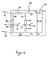
- the apparatus comprises a voltage sensing circuit for sensing the supply voltage to the DC-DC converter 45 as explained below with reference to Figure 4 .
- this shows an example of a voltage sensing circuit 78 connected between the vehicle battery and the DC-DC converter 45.
- the voltage sensing circuit 78 comprises a first branch 80 extending between the positive terminal 82 of the vehicle battery and a first terminal 84 of the DC-DC converter 45, and a second branch 86 extending between the negative terminal 88 of the vehicle battery and a second terminal 90 of the DC-DC converter 45.
- a current sense resistor 92 of known resistance is connected in the first branch 80, whilst the second branch 86 is connected to ground GND.
- a third branch 94 of the voltage sense circuit 78 is connected between the first and second branches 80, 86 to one side of the current sense resistor 92, and a fourth branch 96 is connected parallel to the third branch 94, between the first and second branches 80, 86, on the other side of the current sense resistor 92.
- the third branch 94 includes a first pair of resistors 98a, 98b, connected in series
- the fourth branch 96 includes a second pair of resistors 100a, 100b, connected in series.
- the first pair of resistors 98a, 98b are used to determine the voltage (Va) at a first bias point 102 between the first pair of resistors 98a, 98b.
- the second pair of resistors 100a, 100b are used to determine the voltage (Vb) at a second bias point 104 between the second pair of resistors 100a, 100b.
- the voltages at the bias points 102, 104 substantially correspond to the respective voltages on either side of the current sense resistor 92 because the resistors 98a and 100a are each of high resistance.
- Signals 106, 108 indicative of the voltages at the respective bias points 102, 104 are provided to respective analogue inputs of the microprocessor 26 of the ECU 24.
- the current sense resistor 92 has a low tolerance value to ensure that calculations are accurate.
- the current sense resistor 92 is also able to withstand the high powers associated with the injector drive circuit 6a.
- the microprocessor 26 calculates the output power of the DC-DC converter 45.
- the output power of the DC-DC converter 45 is determined using a suitable function map, for example one obtained from simulating the engine running under various conditions.
- the output power of the DC-DC converter 45 is a function of the battery voltage, and the current (I) supplied to the DC-DC converter 13, as expressed in equation 5 below:
- DC - DC_converter_power fn I ⁇ battery_voltage
- the battery voltage remains at about 13.5 Volts during engine running, and hence the output power of the DC-DC converter 45 is directly related to the current supplied to the DC-DC converter 45 by the relationship in equation 6 below:
- DC - DC_converter_power fn I
- the microprocessor 26 compares the calculated value of the output power of the DC-DC converter 45 with a predetermined threshold value, and if this calculated output power substantially equals, or exceeds this predetermined threshold value, then a decision is made to reduce the load and/or speed under which the engine is currently running in.
- the ICU 22 ( Figure 1 ) calculates a reduced-load sequence of injection events, which may involve disabling some or all of the pre-, and or post-injection events, from the previously calculated required sequence of injection events, since these types of injection event are of lower priority than the main injection events.
- the internal control circuit (not shown) of the DC-DC converter 45 modifies the duty-cycle and/or frequency of the PWM signal 58 driving the DC-DC converter 45 to reduce the output power of the DC-DC converter 45.
- the step of calculating the actual power output of the DC-DC converter 45 is not essential to the present invention. Since the voltage signals that are monitored in the first and second embodiments of the invention are directly related to the output power of the DC-DC converter 45, these signals could be compared to suitable threshold levels without first being converted into the output power of the DC-DC converter 45.
- an alternative embodiment of the invention is envisaged in which the duty-cycle D, or average voltage V AV of the PWM drive signal 58 of the DC-DC converter 45 is compared to a suitable threshold level, and a reduced-load injection event sequence calculated if the duty-cycle D or average voltage V AV equals or exceeds this threshold level.
- the input current I which is calculated in the second embodiment of the invention, could be compared to a suitable threshold level.
- An advantage of the techniques described above is that they are primarily hardware-based, and as such they do not provide a significant drain on the processing power of the microprocessor 26 of the ECU 24. This means that these techniques can be incorporated into existing ECUs without requiring additional or upgraded microprocessors, which are expensive. Implementing the technique of the first embodiment of the invention is particularly inexpensive, because the cost associated with connecting the drive signal of the DC-DC converter 45 to the microprocessor 26 is negligible.
- injectors of the discharge-to-inject variety have been specifically described herein, the invention is equally suited to other types of fuel injectors, in particular fuel injectors of the 'charge-to-inject' variety, in which an injection event is initiated by increasing the voltage across the piezoelectric stack.
Abstract
Description
- The invention relates to a method of controlling fuel injection in an engine. More specifically, the invention relates to a method of controlling piezoelectrically actuated fuel injectors in order to improve the performance of a vehicle engine, particular at high engine speeds. The invention also relates to an apparatus for implementing the method of the invention.
- In a direct injection internal combustion engine, a fuel injector is provided to deliver a charge of fuel to a combustion chamber prior to ignition. Typically, the fuel injector is mounted in a cylinder head with respect to the combustion chamber such that its tip protrudes slightly into the chamber in order to deliver a charge of fuel into the chamber.
- One type of fuel injector that is particularly suited for use in a direct injection engine is a so-called piezoelectric injector. Such an injector allows precise control of the timing and total delivery volume of a fuel injection event. This permits improved control over the combustion process which is beneficial in terms of exhaust emissions.
- A known
piezoelectric injector 2 and its associatedcontrol system 4 are shown schematically inFigure 1 . Thepiezoelectric injector 2 is connected to aninjector drive circuit 6 by way of first and second power supply leads 8, 10. Thepiezoelectric injector 2 includes apiezoelectric actuator 12 that is operable to control the position of aninjector valve needle 14 relative to avalve needle seat 16. Thepiezoelectric actuator 12 includes astack 18 of piezoelectric elements that expands and contracts in dependence on a differential voltage supplied by theinjector drive circuit 6. - The axial position, or 'lift', of the
valve needle 14 is controlled by varying the differential voltage across theactuator 12. By application of an appropriate voltage differential across theactuator 12, thevalve needle 14 is either caused to disengage thevalve seat 16, in which case fuel is delivered into an associated combustion chamber (not shown) through a set ofnozzle outlets 20, or is caused to engage thevalve seat 16, in which case fuel delivery through theoutlets 20 is prevented. -
Piezoelectric injectors 2 are typically grouped together in banks. As described inEP1400676 , each bank ofpiezoelectric injectors 2 has itsown drive circuit 6 for controlling operation of thepiezoelectric injectors 2. The circuitry typically includes a power supply, which steps-up the voltage generated by a power source from 12 Volts to a higher voltage, and storage capacitors for storing charge and, thus, energy. The higher voltage is applied across the storage capacitors, which are used to power the charging and discharging of thepiezoelectric injectors 2 for each injection event. - As shown in
Figure 1 ,piezoelectric injectors 2 are controlled by an injector control unit 22 (ICU) that forms an integral part of an engine control unit 24 (ECU). The ICU 22 typically comprises amicroprocessor 26 andmemory 28. The ECU 24 monitors a plurality ofengine operating parameters 30, and calculates an engine power requirement signal (not shown), which is input to theICU 22. Examples of theengine operating parameters 30 include engine speed, driver torque demand, manifold inlet pressure and manifold inlet temperature. In turn, the ICU 22 calculates a required injection event sequence to provide the required power for the engine and operates theinjector drive circuit 6 accordingly. - Each
piezoelectric injector 2 is operable to deliver one or more injections of fuel within an injection event sequence. For example, an injection event sequence may include one or more so-called 'pre-' or 'pilot' injections, one or more main injections, and one or more 'post' injections. The use of several such injections within an injection event sequence can increase the combustion efficiency of the engine in order to meet emissions, fuel consumption and NVH (Noise Vibration Harshness) targets. - A problem can occur when an engine is run at high speeds and/or loads, wherein the ICU may calculate certain injection event sequences that can overload the power supply to the
injector drive circuit 6. If this occurs, theinjector drive circuit 6 is unable to provide sufficient power to operate thepiezoelectric injectors 2 according to the required injection event sequence. This may cause thepiezoelectric injectors 2 to deliver less fuel than is required, which in turn may result in an undesirable and unexpected loss of power to the vehicle engine, or the engine misfiring. - It is an object of the present invention to provide an improved method of operating fuel injection equipment, which prevents the aforementioned problem from occurring. The invention also aims to provide an improved apparatus for operating fuel injection equipment.
- According to a first aspect of the present invention, there is provided a method of controlling fuel injection in an engine, the engine comprising at least one fuel injector which is connected to an injector drive circuit powered by a power supply, the power supply being connectable to a power source such as a vehicle battery, and the method comprising: determining an injection event sequence comprising one or more injection events of the at least one fuel injector in dependence upon at least one engine operating parameter; determining the output power or a parameter related to the output power of the power supply; comparing the output power or the parameter to a predetermined threshold level; and determining a modified injection event sequence comprising one or more injection events in the event that the output power or the parameter is substantially equal to or greater than the predetermined threshold level.
- The first aspect of the present invention provides a method of controlling fuel injection in an engine such that the risk of overloading of the power supply is reduced. Upon determining an injection event sequence for controlling the one or more injectors in the engine, the output power of the power supply, or a parameter related to the output power, is determined and then compared to a predetermined threshold level. In the event that the calculated output power or related parameter equals or exceeds the threshold level then a modified injection event sequence can be determined that does not overload the power supply.
- The injection event sequence may be modified so as to reduce the load and/or speed at which the engine is presently operating. Modifying the injection event sequence prevents overloading of the power supply in the event that the engine power demand is too high, and hence avoids the undesirable and unexpected loss of power to the vehicle engine, or the misfiring, which can otherwise result from overloading the power supply.
- The step of modifying the injection event sequence may include disabling one or more of the low-priority injection events, for example one or more of the pre- or post-injection events. Such a modified injection event sequence is also referred to hereinafter as a 'reduced-load injection event sequence'. Alternatively, or additionally, the step of modifying the injection event sequence may involve taking any other suitable action that would ultimately result in the engine running under a reduced-power regime, for example reducing the duration and/or frequency of the injection events.
- The step of determining the output power of the power supply may comprise monitoring a variable related to the output power of the power supply, and deriving the output power of the power supply from the monitored variable. The method may further comprise using a function map to determine the output power of the power supply from the monitored variable. The parameter related to the output power of the power supply may be a variable indicative of the output power of the power supply.
- The variable related to the output power of the power supply may be the current drawn by the power supply, for example from a vehicle battery to which the power supply is connected. In order to determine the current drawn by the power supply, the method may comprise determining the potential difference across a sense resistor connected between the power supply and a vehicle battery. The sense resistor preferably has a low tolerance, such that its resistance is known to a suitably high degree of accuracy. The current drawn by the power supply may be determined from the potential difference across the sense resistor. The method may further comprise determining the output power of the power supply using a function map relating the current drawn by power supply and the output power of power supply.
- Alternatively, the variable related to the output power of the power supply may be a duty-cycle or an average voltage of a drive signal of the power supply. The power supply may comprise a DC-DC converter. The drive signal of the DC-DC converter may be connected to an input of the microprocessor of the engine control unit ECU, and the microprocessor may be configured to monitor the drive signal and determine the output power of the power supply. The cost associated with connecting the drive signal of the DC-DC converter to the microprocessor is negligible, which makes this method particularly advantageous.
- The power supply may comprise a multiphase DC-DC converter, in which case the method may comprise monitoring the drive signal in a single phase of the DC-DC converter. The duty-cycle and average voltage of this signal is indicative of the output power of the multiphase DC-DC converter, and suitable scaling in accordance with standard techniques enables the output power of the multiphase DC-DC converter to be determined.
- As mentioned above, the method may comprise using a function map, or a suitable look-up table, to determine the output power of the power supply. The function map or look-up table may relate the output power of the power supply to the monitored variable, for example the duty-cycle or average voltage of the drive signal of the power supply, or the current drawn by the power supply. The method may be performed by a motor vehicle engine control unit (ECU). The function map or look-up table may be stored in the memory of the ECU, which may be accessed by the microprocessor.
- As described in the background to the invention, the process of calculating an injection event sequence may include monitoring at least one engine operating parameter such as engine speed, driver torque demand, manifold inlet pressure and manifold inlet temperature, calculating an engine power requirement based on the at least one engine operating parameter, and determining an injection event sequence to provide the required power for the engine. Preferably the method outlined above is performed by the ECU.
- According to a second aspect of the invention there is provided an apparatus for controlling fuel injection from at least one fuel injector of an engine, the apparatus comprising: an injector drive circuit for connection to the at least one fuel injector; a power supply for supplying power to the injector drive circuit, the power supply being connectable to a power source such as a vehicle battery; and processing means arranged to: (i) determine an injection event sequence of the at least one fuel injector in dependence upon at least one engine operating parameter; (ii) determine the output power or a parameter related to the output power of the power supply; (iii) compare the output power or the parameter to a predetermined threshold level; and (iv) determine a modified injection event sequence in the event that the output power or the parameter is substantially equal to or greater than the predetermined threshold level.
- The apparatus is preferably part of an engine control unit (ECU) of a vehicle. The power supply means may comprise a switched-mode power supply, preferably a DC-DC converter. The DC-DC converter may be controlled by a drive signal of a switching or control circuit internal to the DC-DC converter.
- In a first embodiment of the invention, the apparatus comprises a connection between the DC-DC converter and an input of the processing means, such that the drive signal of the DC-DC converter is provided to the processing means through the connection. The DC-DC converter may be a multiphase DC-DC converter having a plurality of phases. Each phase of the DC-DC converter may comprise a switch, and the connection may extend between a switch terminal of a single switch and the input of the processing means. Monitoring the drive signal of the DC-DC converter utilises only a single input on the processing means, which is advantageous and does not require additional analogue to digital inputs to be included on the microprocessor, which can be expensive.
- A low pass filter may be located in the connection between the DC-DC converter and the processing means. The low pass filter may be arranged to output a signal indicative of the duty-cycle of the drive signal of the DC-DC controller to the processing means. The processing means may be configured to determine the output power of the power supply means from the duty-cycle of the drive signal. A function map or look-up table stored in the memory of the ECU and accessible by the processing means may be used for this purpose as described above in relation to the first aspect of the invention.
- In a second embodiment of the invention, the apparatus comprises a sense resistor of substantially known resistance connected between the power supply means and a vehicle battery. The processing means may be arranged to monitor the potential difference across the sense resistor and determine the current into the power supply means from the known resistance of the sense resistor and the potential difference across the sense resistor. The output power of the power supply means may be determined using a function map or look-up table. As described above in relation to the first aspect of the invention, the function map or look-up table may relate the current into the power supply and the output power of power supply.
- The inventive concept encompasses a method of controlling at least one fuel injector connected in an injector drive circuit, the method comprising: determining a power supply parameter of a power supply used to supply power to the injector drive circuit; comparing the power supply parameter to a predetermined power supply parameter threshold value; and determining a reduced-load injection event sequence in the event that the power supply parameter is substantially equal to or greater than the predetermined power supply parameter threshold level.
- The inventive concept also encompasses an apparatus for controlling at least one fuel injector, the apparatus comprising: an injector drive circuit for connection to the at least one fuel injector; power supply means for supplying power to the injector drive circuit; and processing means for: (i) determining a power supply parameter of the power supply means; (ii) comparing the power supply parameter to a predetermined power supply parameter threshold level; and (iii) determining a reduced-load injection event sequence of the at least one fuel injector in the event that the power supply parameter is substantially equal to or greater than the predetermined power supply parameter threshold level.
- The power supply parameter may be the output power of the power supply, or a parameter indicative of, or related to the output power of the power supply. For example, the power supply parameter may be the duty-cycle of a drive signal of the power supply, the average voltage of said drive signal or a signal indicative of the current drawn by the power supply. For example, in an alternative embodiment of the invention the duty-cycle of the drive signal of the power supply could be compared to a predetermined threshold level and a reduced-load injection event sequence calculated if this parameter substantially equals or exceeds the predetermined threshold level. This method would eliminate the step of calculating the actual power output of the power supply in physical units, thereby reducing the burden on the microprocessor.
- It will be appreciated that optional features described above in relation to the various method aspects of the invention are equally applicable to the various apparatus aspects of the invention, and vice versa.
- Reference has already been made to
Figure 1 , which is a schematic representation of a known piezoelectric injector and its associated control system. - In order that it may be more readily understood, the present invention will now be described with reference also to the following figures, in which:
-
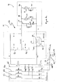
Figure 2 is a circuit diagram of an injector drive circuit, powered by a DC-DC converter, and modified in accordance with a first embodiment of the present invention; -
Figure 3 is a schematic diagram showing the steps performed in determining the power output of the DC-DC converter inFigure 2 ; and -
Figure 4 is a circuit diagram of a voltage sensing circuit used to determine the output power of the DC-DC converter of a drive circuit similar to the drive circuit inFigure 2 , in accordance with a second embodiment of the present invention. - The present invention is implemented in an engine control unit (ECU) 24, such as that shown in
Figure 1 , including the injector control unit (ICU) 22 and thedrive circuit 6. In a first embodiment of the invention, the drive circuit differs from that shown inFigure 1 , as described below with reference toFigure 2 . -
Figure 2 shows an injector drive circuit 6a in accordance with a first embodiment of the present invention. The injector drive circuit 6a includes a switchingcircuit 31 in conjunction with an injector bank circuit 32 comprising first and second injectors, 34 and 36 respectively. Each of theinjectors Figure 1 , having a respectivepiezoelectric actuator 12. The piezoelectric actuators are considered electrically equivalent to capacitors, and are represented as such inFigure 2 . - The switching
circuit 31 includes three input voltage rails: a high voltage rail VHI (typically 255 V), a mid voltage rail VMID (typically 55 V), and a ground rail GND. The switchingcircuit 31 also includes a high side voltage output V1 and a low side voltage output V2 and is operable to connect the high side voltage output V1 to either the high voltage rail VHI or the ground rail GND, through an inductor L, by means of first and second switch means Q1, Q2. The first switch means shall be referred to as the charge switch Q1 and the second switch means shall be referred to as the discharge switch Q2. A first diode DQ1 is connected across the charge switch Q1 and a second diode is connected across the discharge switch Q2. - The switching
circuit 31 is also provided with a diode D1 that connects the high side voltage output V1 to the high voltage rail VHI. The diode D1 is oriented to permit current to flow from the high side voltage output V1 to the high voltage rail VHI but to prevent current flow from the high voltage rail VHI to the high side voltage output V1. - The injector bank circuit 32 comprises first and
second branches 38, 40, each of which is connected in parallel between the high side voltage output V1 and the low side voltage output V2 of the switchingcircuit 31. Thus, the high side voltage output V1 of the switchingcircuit 31 is also a high side voltage input to the injector bank circuit 32 and the low side voltage output V2 of the switchingcircuit 31 is a low side voltage input to the bank circuit 32. Thefirst branch 38 of the injector bank circuit 32 contains thefirst injector 34 and the second branch 40 contains thesecond injector 36. Eachbranch 38, 40 also includes an associated injector select switch QS1, QS2 by which means the respective one of the injectors, 34 or 36, can be selected for operation, as will be described later. The injector bank circuit 32 also includes athird branch 41 connected in parallel with the first andsecond branches 38, 40. Thethird branch 41 comprises a recirculation switch RSQ connected in series with a diode RD1. Operation of the recirculation switch RSQ is described in more detail later. - The low side voltage output V2 of the injector bank circuit 32 is connected to the mid voltage rail VMID via a current sensing and control means 42. The current sensing and control means 42 comprises a
current comparator module 43 connected in parallel with asense resistor 44. Thecurrent comparator module 43 is operable to monitor the current flowing through thesense resistor 44. The operation of the current sensing and control means 42 is not described in detail herein, but is described in more detail in applicant's co-pending applicationEP 06256140.2 - A DC-
DC converter 45, which is described in more detail later, supplies energy to the injector drive circuit 6a. The DC-DC converter 45 is connected to a vehicle battery (not shown) and boosts the voltage of the vehicle battery (e.g. 12 Volts) to a higher voltage (e.g. 55 Volts). The DC-DC converter 45 regulates the voltage of the mid voltage rail VMID at 55 Volts, as described in more detail later. A first energy storage capacitor C1 is connected between the high and mid voltage rails VHI, VMID, and a second energy storage capacitor C2 is connected between the mid and ground voltage rails VMID, GND. The capacitors C1, C2 store energy which is used to power the charging and discharging of thepiezoelectric injectors - The
piezoelectric injectors injector actuator 12 to contract, thus lifting the injector valve needle 14 (Figure 1 ) away from the valve needle seat 16 (Figure 1 ) to permit fuel delivery through the outlets 20 (Figure 1 ). This process is referred to hereinafter as 'discharging' the injector, and occurs when the injector drive circuit 6a is operated in a 'discharge phase'. - Conversely, in order to terminate an injection event, the injector drive circuit 6a causes the differential voltage between the high and low voltage terminals of the injector, V1 and V2, to transition from a relatively low voltage (e.g. 55 V), to a relatively high voltage (e.g. 255 V), which increases the actuator voltage, causing the actuator to expand, thus seating the injector valve needle 14 (
Figure 1 ) back on the valve needle seat 16 (Figure 1 ) to terminate fuel delivery through the outlets 20 (Figure 1 ). This process is referred to hereinafter as 'charging' the injector, and occurs when the injector drive circuit 6a is operated in a 'charge phase'. There now follows a brief description of the discharge and charge phases of operation of the drive circuit 6a. - To initiate the discharge phase, the discharge switch Q2 is closed and the charge switch Q1 remains open. As described in more detail in applicant's co-pending application
EP 06254039.8 microprocessor 26 and the current sensing and control means 42, the discharge switch Q2 is rapidly pulsed on and off to regulate the flow of current. Aninjector 34 or 36 (Figure 1 ) is selected for injection by closing the associated injector select switch QS1 or QS2 respectively. For example, to inject from thefirst injector 34, the first injector select switch QS1 is closed and current flows from the positive terminal of the second capacitor C2, through the current sensing and control means 42, through the terminals of the selected first injector 34 (from the low side - to the high side +), through the inductor L, through the discharge switch Q2 and back to the negative side of the second capacitor C2. No current is able to flow through the unselectedsecond injector 36 because the associated injector select switch QS2 remains open. - To charge the
injectors EP 06254039.8 microprocessor 26 and the current sensing and control means 42, the charge switch Q1 is rapidly pulsed on and off to regulate the flow of current. The first capacitor C1, when fully charged, has a potential difference of about 255 Volts across it, and so closing the charge switch Q1 causes current to flow around the charge circuit, from the positive terminal of the first capacitor C1, through the charge switch Q1 and the inductor L, through theinjectors 34, 36 (from the high side terminals + to the low side terminals -), through the current sensing and control means 42, and back to the negative terminal of the first capacitor C1. In the charge phase, the previously dischargedinjector 34 is charged, which causes the injector valve needle 14 (Figure 1 ) of theinjector 34 to close to terminate the injection of fuel into the associated cylinder (not shown). - The DC-
DC converter 45 maintains the voltage across the second capacitor C2 substantially at 55 Volts so that the second capacitor is ready for use in subsequent discharge phases. In order that the first capacitor C1 is ready for use in subsequent charge phases, energy is replenished to the first capacitor C1 during a so-called 'regeneration phase' of operation of the drive circuit 6a. To commence the regeneration phase, the regeneration switch RSQ and the discharge switch Q2 are closed whilst the charge switch Q1 remains open. A current flows through the diode RD1 and the regeneration switch RSQ in thethird branch 41 of the injector bank circuit 32, through the inductor L and discharge switch Q2 to ground GND. The discharge switch Q2 is then opened, and because of the inductance of the inductor L, some current continues to flow for a short while after the discharge switch Q2 is opened. This current flows through the diode DQ1 connected across the charge switch Q1 and into the positive terminal of the first capacitor C1 to partially charge the first capacitor C1. The discharge switch Q2 is repeatedly closed and opened to further charge the first capacitor C1 until the potential difference across the first capacitor C1 is increased to about 255 Volts and the potential across the second capacitor is about 55 Volts. The regeneration process is described in more detail inWO 2005/028836A1 . - Referring again to the DC-
DC converter 45, this is a three-phase DC-DC converter 45 comprising threebranches 46a, 46b, 46c. Eachbranch 46a, 46b, 46c includes an inductor 47a, 47b, 47c connected in series with a respective switch 48a, 48b, 48c. The switches 48a, 48b, 48c are power transistors, such as metal-oxide semiconductor field-effect transistors (MOSFET) and are controlled by an internal control circuit (not shown) of the DC-DC converter 45. - Each
branch 46a, 46b, 46c of the DC-DC converter 45 is connecter to the drive circuit 6a at a point between the first and second storage capacitors C1, C2. A diode 50a, 50b, 50c, is located between eachbranch 46a, 46b, 46c of the DC-DC converter 45 and the drive circuit 6a. The diodes 50a, 50b, 50c are oriented to permit current to flow from the DC-DC converter 45 to the drive circuit 6a, but to prevent current flow from the drive circuit 6a to the DC-DC converter 45. - The DC-
DC converter 45 regulates the voltage of the mid voltage rail VMID at 55 Volts. The DC-DC converter 45 must supply sufficient power to the injector drive circuit 6a to regulate the potential of the mid voltage rail VMID at 55 Volts whilst the injector drive circuit 6a operates thefuel injectors ICU 22. In order to supply power to the injector drive circuit 6a, the switches 48a, 48b, 48c of the DC-DC converter 45 are rapidly switched on and off under the control of a drive signal generated by the internal control circuit (not shown) of the DC-DC converter 45. The drive signal is a pulse width modulated (PWM) signal. The power output of the DC-DC converter 45 is governed by the duty-cycle and frequency of the PWM signal. The internal control circuit of the DC-DC converter 45 determines the duty-cycle and frequency of the PWM signal in dependence of the power required by the injector drive circuit 6a to operate thefuel injectors ICU 22. - As shown in
Figure 2 , the first embodiment of the present invention includes aconnection 52 between the DC-DC converter 45 and an analogue input to themicroprocessor 26 of theECU 24. Alow pass filter 53, comprising aresistor 54 and a capacitor 56, is provided in theconnection 52. A gate terminal 57 of the transistor 48a in thefirst branch 46a of the DC-DC converter 45 is connected to an input of thelow pass filter 53, and the output from thelow pass filter 53 is connected to the analogue input of themicroprocessor 26. In this configuration, the PWM drive signal of the DC-DC converter 45, which is used to control the rapid switching of the DC-DC converter 45 as described above, is provided to thelow pass filter 53. Thelow pass filter 53 converts the PWM signal into an analogue signal, which is provided to the analogue input of themicroprocessor 26 as described in further detail below with reference toFigure 3 . - Referring to
Figure 3 , this shows thePWM signal 58 generated by the internal control circuit (not shown) of the DC-DC converter 45. ThePWM signal 58 has an on-time (τ), a period (T), and varying between zero and five Volts. The duty-cycle (D) of thePWM signal 58 is given byequation 1 below:
- The
PWM signal 58 is provided to thelow pass filter 53, which outputs ananalogue signal 60 corresponding to the average voltage (VAV) of thePWM signal 58. The average voltage signal 60 (VAV) of thePWM signal 58 is given byequation 2 below:
- The
average voltage signal 60 is sampled by the analogue input of themicroprocessor 26, and is converted to adigital voltage signal 62 by an analogue todigital converter 64. A scaling anderror checking module 66 of themicroprocessor 26 performs scaling and error checking functions on thedigital voltage signal 62. Apower monitor module 68 then determines theoutput power 72 of the DC-DC converter 45 from thedigital voltage signal 62, thevoltage 74 of the vehicle battery and thevoltage 76 of the DC-DC converter 45, which is 55 Volts in this example. As described in more detail below, thepower monitor module 68 uses afunction map 70 to determine theoutput power 72 of the DC-DC converter 45. - For a given
voltage 76 of the power supply (55 Volts in this example) theoutput power 72 of the DC-DC converter 45 is a function of thebattery voltage 74 and the average voltage VAV of thePWM signal 58, as represented byequation 3 below:
- The
function map 70 may be visualised as a graph in which the z-axis corresponds to theoutput power 72 of the DC-DC converter 45, the x-axis corresponds to VAV, and the y-axis is thebattery voltage 74. The function map may be generated from empirical calculations, modelling or simulations. For example, thefunction map 70 could be created by running an engine at various speeds and loads whilst measuring theoutput power 72 of the DC-DC converter 45 and monitoring the average voltage VAV of thePWM signal 58 and thebattery voltage 74. Thebattery voltage 74 is a parameter that is monitored by theECU 24 as standard, and so is known by themicroprocessor 26. - It should be noted that during engine running, the
battery voltage 74 remains at approximately 13.5 Volts, and so thefunction map 70 then reduces to a two-dimensional relationship between theoutput power 72 of the DC-DC converter 45 and the average voltage VAV of thePWM signal 58 as represented byequation 4 below:
- Hence, using the
function map 70, theoutput power 72 of the DC-DC converter 45 can be inferred from the average voltage VAV of thePWM signal 58. - Once the
output power 72 of the DC-DC converter has been determined, themicroprocessor 26 compares the calculatedoutput power 72 to a predetermined threshold value. The predetermined threshold value may be equal to, but is preferably suitably lower than the maximum output power of the DC-DC converter 45 at the present battery voltage. The maximum output power of the DC-DC converter 45 varies according to the battery voltage. However, the maximum output power of the DC-DC converter 45 is known for a given battery voltage, which allows suitable threshold values to be chosen. - If the calculated
output power 72 substantially equals or exceeds the predetermined threshold value, then a decision is made to reduce the load and/or speed under which the engine is currently running. In order to reduce the load and/or speed of the engine, the ICU 22 (Figure 1 ) calculates a reduced-load sequence of injection events, which may involve disabling some or all of the pre-, and or post-injection events, from the previously calculated required sequence of injection events, since these types of injection event are of lower priority than the main injection events. The injector drive circuit 6a requires less power to operate theinjectors DC converter 45 modifies the duty-cycle and/or frequency of thePWM signal 58 driving the DC-DC converter 45, such that the power output of the DC-DC converter 45 is reduced. - Other embodiments of the invention are envisaged in which the
PWM signal 58 from the DC-DC converter 45 is connected directly to a frequency input of themicroprocessor 26 instead of via alow pass filter 53. In such embodiments, themicroprocessor 26 would be configured to detect and filter the duty-cycle of thePWM signal 58. - In a second embodiment of the present invention, the injector drive circuit 6a does not include the
connection 52 from the gate terminal 57 of the transistor 48a to themicroprocessor 26, which is shown inFigure 2 . Instead, the apparatus comprises a voltage sensing circuit for sensing the supply voltage to the DC-DC converter 45 as explained below with reference toFigure 4 . - Referring to
Figure 4 , this shows an example of avoltage sensing circuit 78 connected between the vehicle battery and the DC-DC converter 45. Thevoltage sensing circuit 78 comprises a first branch 80 extending between thepositive terminal 82 of the vehicle battery and afirst terminal 84 of the DC-DC converter 45, and asecond branch 86 extending between the negative terminal 88 of the vehicle battery and a second terminal 90 of the DC-DC converter 45. Acurrent sense resistor 92 of known resistance is connected in the first branch 80, whilst thesecond branch 86 is connected to ground GND. - A third branch 94 of the
voltage sense circuit 78 is connected between the first andsecond branches 80, 86 to one side of thecurrent sense resistor 92, and a fourth branch 96 is connected parallel to the third branch 94, between the first andsecond branches 80, 86, on the other side of thecurrent sense resistor 92. The third branch 94 includes a first pair of resistors 98a, 98b, connected in series, and the fourth branch 96 includes a second pair of resistors 100a, 100b, connected in series. - The first pair of resistors 98a, 98b are used to determine the voltage (Va) at a
first bias point 102 between the first pair of resistors 98a, 98b. Similarly, the second pair of resistors 100a, 100b are used to determine the voltage (Vb) at a second bias point 104 between the second pair of resistors 100a, 100b. The voltages at the bias points 102, 104 substantially correspond to the respective voltages on either side of thecurrent sense resistor 92 because the resistors 98a and 100a are each of high resistance. -
Signals microprocessor 26 of theECU 24. Themicroprocessor 26 is configured to calculate the current (I) being supplied to the DC-DC converter 45 from the ratio of the difference (ΔV) between the first and second voltage values Va, Vb, and the known resistance (R) of the current sense resistor 92: i.e. using I=ΔV/R. Thecurrent sense resistor 92 has a low tolerance value to ensure that calculations are accurate. Thecurrent sense resistor 92 is also able to withstand the high powers associated with the injector drive circuit 6a. - Once the current being supplied to the DC-
DC converter 45 has been determined, themicroprocessor 26 calculates the output power of the DC-DC converter 45. In common with the first embodiment of the invention described above, the output power of the DC-DC converter 45 is determined using a suitable function map, for example one obtained from simulating the engine running under various conditions. The output power of the DC-DC converter 45 is a function of the battery voltage, and the current (I) supplied to the DC-DC converter 13, as expressed in equation 5 below:
- Also as described above with reference to the first embodiment of the invention, the battery voltage remains at about 13.5 Volts during engine running, and hence the output power of the DC-
DC converter 45 is directly related to the current supplied to the DC-DC converter 45 by the relationship inequation 6 below:
- In common with the first embodiment of the invention described above, the
microprocessor 26 compares the calculated value of the output power of the DC-DC converter 45 with a predetermined threshold value, and if this calculated output power substantially equals, or exceeds this predetermined threshold value, then a decision is made to reduce the load and/or speed under which the engine is currently running in. In order to reduce the load and/or speed of the engine, the ICU 22 (Figure 1 ) calculates a reduced-load sequence of injection events, which may involve disabling some or all of the pre-, and or post-injection events, from the previously calculated required sequence of injection events, since these types of injection event are of lower priority than the main injection events. Since the injector drive circuit 6a requires less power to operate theinjectors DC converter 45 modifies the duty-cycle and/or frequency of thePWM signal 58 driving the DC-DC converter 45 to reduce the output power of the DC-DC converter 45. - As an alternative to the voltage sensing circuit shown in
Figure 4 , it should be appreciated that other embodiments of the invention could use a differential voltage circuit. - It should also be appreciated that whilst it is preferable to calculate the actual output power of the DC-
DC converter 45 and compare this value to a threshold level, the step of calculating the actual power output of the DC-DC converter 45 is not essential to the present invention. Since the voltage signals that are monitored in the first and second embodiments of the invention are directly related to the output power of the DC-DC converter 45, these signals could be compared to suitable threshold levels without first being converted into the output power of the DC-DC converter 45. For example, an alternative embodiment of the invention is envisaged in which the duty-cycle D, or average voltage VAV of thePWM drive signal 58 of the DC-DC converter 45 is compared to a suitable threshold level, and a reduced-load injection event sequence calculated if the duty-cycle D or average voltage VAV equals or exceeds this threshold level. Alternatively, the input current I, which is calculated in the second embodiment of the invention, could be compared to a suitable threshold level. - An advantage of the techniques described above, is that they are primarily hardware-based, and as such they do not provide a significant drain on the processing power of the
microprocessor 26 of theECU 24. This means that these techniques can be incorporated into existing ECUs without requiring additional or upgraded microprocessors, which are expensive. Implementing the technique of the first embodiment of the invention is particularly inexpensive, because the cost associated with connecting the drive signal of the DC-DC converter 45 to themicroprocessor 26 is negligible. - Whilst injectors of the discharge-to-inject variety have been specifically described herein, the invention is equally suited to other types of fuel injectors, in particular fuel injectors of the 'charge-to-inject' variety, in which an injection event is initiated by increasing the voltage across the piezoelectric stack.
- It will be appreciated that various modifications or alternations may be made to the techniques described above without departing from the scope of the invention as defined in the appended claims.
Claims (22)
- A method of controlling fuel injection in an engine, the engine comprising at least one fuel injector (34,36) which is connected to an injector drive circuit (6a) powered by a power supply (45), the power supply being connectable to a power source such as a vehicle battery, and the method comprising:determining an injection event sequence comprising one or more injection events of the at least one fuel injector (34,36) in dependence upon at least one engine operating parameter (30);determining the output power (72) or a parameter (D,VAV, 106,108,I) related to the output power (72) of the power supply (45);comparing the output power (72) or the parameter (D,VAV, 106,108,I) to a predetermined threshold level; anddetermining a modified injection event sequence comprising one or more injection events in the event that the output power (72) or the parameter (D,VAV, 106,108,I) is substantially equal to or greater than the predetermined threshold level, the modified injection event sequence being such that it does not overload the power supply.
- The method of Claim 1, further comprising:monitoring a variable (D,VAV,106,108,I) related to the output power (72) of the power supply (45); andderiving the output power (72) of the power supply (45) from the monitored variable (D,VAV,106,108,I).
- The method of Claim 2, further comprising using a function map (70) to determine the output power (72) of the power supply (45) from the monitored variable (D,VAV,106,108,I).
- The method of Claim 2 or Claim 3, wherein the variable is a duty-cycle (D) of a drive signal (58) of the power supply (45).
- The method of Claim 2 or Claim 3, wherein the variable is an average voltage (VAV) of a drive signal (58) of the power supply (45).
- The method of Claim 2 or Claim 3, wherein the variable is a current (I) drawn by the power supply (45).
- The method of Claim 6, further comprising:determining the potential difference (ΔV) across a sense resistor (92) connected between the power supply (45) and a vehicle battery;calculating the current (I) drawn by the power supply (45) from the potential difference (ΔV) across the sense resistor (92); anddetermining the output power (72) of the power supply (45) using a function map relating the current (I) drawn by power supply (45) and the output power (72) of power supply (45).
- The method of any preceding claim, wherein the power supply (45) comprises a DC-DC converter (45).
- The method of Claim 8 when dependent on Claim 4 or Claim 5, wherein the DC-DC converter (45) is a multiphase DC-DC converter (45), and the method comprises monitoring the drive signal (58) in a single phase (46a) of the DC-DC converter (45).
- The method of any preceding claim, wherein the step of determining a modified injection event sequence includes reducing the number of injections in the injection event sequence.
- The method of any preceding claim, wherein the step of determining a modified injection event sequence includes disabling one or more low priority injections.
- The method of Claim 11, wherein the step of disabling one or more low priority injections includes disabling one or more of the pilot- and/or post-injections.
- The method of any preceding claim, wherein the step of calculating an injection event sequence includes:monitoring the at least one engine operating parameter (30);calculating an engine power requirement based on the at least one engine operating parameter (30); anddetermining an injection event sequence to provide the required power for the engine.
- The method of any preceding claim, wherein the method is performed by a motor vehicle engine control unit (ECU) (24).
- The method of any preceding claim, wherein the modified injection event sequence is a reduced-load injection event sequence.
- An apparatus for controlling fuel injection from at least one fuel injector (34,36) of an engine, the apparatus comprising:an injector drive circuit (6a) for connection to the at least one fuel injector (34,36);a power supply (45) for supplying power to the injector drive circuit (6a), the power supply (45) being connectable to a power source such as a vehicle battery; andprocessing means (26) arranged to:(i) determine an injection event sequence of the at least one fuel injector (34,36) in dependence upon at least one engine operating parameter (30);(ii) determine the output power (72) or a parameter (D,VAV,106,108,I) related to the output power (72) of the power supply (45);(iii) compare the output power (72) or the parameter (D,VAV,106,108,I) to a predetermined threshold level; and(iv) determine a modified injection event sequence in the event that the output power (72) or the parameter (D,VAV,106,108,I) is substantially equal to or greater than the predetermined threshold level, the modified injection event sequence being such that it does not overload the power supply.
- The apparatus of Claim 16, wherein the power supply (45) comprises a DC-DC converter (45) and the apparatus further comprises a connection (52) between the DC-DC converter (45) and an input of the processing means (26), such that a drive signal (58) of the DC-DC converter (45) is provided to the processing means (26) through the connection (52).
- The apparatus of Claim 17, wherein the DC-DC converter (45) is a multiphase DC-DC converter (45) having a plurality of phases (46a,46b,46c), each phase (46a,46b,46c) comprising a switch (48a,48b,48c), and the connection (52) extending between a switch terminal (57) of a single switch (48a) and the input of the processing means (26).
- The apparatus of Claim 17 or 18, further comprising a low pass filter (53) in the connection (52) between the DC-DC converter (45) and the processing means (26), the low pass filter (53) being arranged to output a signal (60) indicative of a duty-cycle (D) of the drive signal (58) of the DC-DC converter (45) to the processing means (26), and the processing means (26) being arranged to determine the output power (72) of the power supply (45) from the duty-cycle (D) of the drive signal (58) using a function map (70) stored in a memory device (28) and accessible by the processing means (26).
- The apparatus of Claim 16, further comprising a sense resistor (92) of known resistance connected between the power supply (45) and a vehicle battery, wherein the processing means (26) is further arranged to:monitor the potential difference across the sense resistor (92);determine the current (I) into the power supply (45) from the known resistance (R) of the sense resistor (92) and the potential difference across the sense resistor (92); anddetermine the output power (72) of the power supply (45) using a function map (70) relating the current (I) into the power supply (45) and the output power (72) of power supply (45).
- The apparatus of any of Claims 16 to 20, wherein the modified injection event sequence is a reduced-load injection event sequence.
- An engine control unit (ECU) (24) of a vehicle, comprising the apparatus of any of Claims 16 to 21.
Priority Applications (4)
| Application Number | Priority Date | Filing Date | Title |
|---|---|---|---|
| EP07019416A EP2045459B1 (en) | 2007-10-04 | 2007-10-04 | A method of controlling fuel injection apparatus |
| AT07019416T ATE548550T1 (en) | 2007-10-04 | 2007-10-04 | METHOD FOR CONTROLLING A FUEL INJECTION DEVICE |
| US12/231,815 US8108126B2 (en) | 2007-10-04 | 2008-09-05 | Method of controlling fuel injection apparatus |
| JP2008258430A JP5356767B2 (en) | 2007-10-04 | 2008-10-03 | Method for controlling a fuel injection device |
Applications Claiming Priority (1)
| Application Number | Priority Date | Filing Date | Title |
|---|---|---|---|
| EP07019416A EP2045459B1 (en) | 2007-10-04 | 2007-10-04 | A method of controlling fuel injection apparatus |
Publications (2)
| Publication Number | Publication Date |
|---|---|
| EP2045459A1 EP2045459A1 (en) | 2009-04-08 |
| EP2045459B1 true EP2045459B1 (en) | 2012-03-07 |
Family
ID=39148757
Family Applications (1)
| Application Number | Title | Priority Date | Filing Date |
|---|---|---|---|
| EP07019416A Not-in-force EP2045459B1 (en) | 2007-10-04 | 2007-10-04 | A method of controlling fuel injection apparatus |
Country Status (4)
| Country | Link |
|---|---|
| US (1) | US8108126B2 (en) |
| EP (1) | EP2045459B1 (en) |
| JP (1) | JP5356767B2 (en) |
| AT (1) | ATE548550T1 (en) |
Families Citing this family (7)
| Publication number | Priority date | Publication date | Assignee | Title |
|---|---|---|---|---|
| EP1927743A1 (en) * | 2006-11-30 | 2008-06-04 | Delphi Technologies, Inc. | Detection of faults in an injector arrangement |
| ATE548550T1 (en) * | 2007-10-04 | 2012-03-15 | Delphi Tech Holding Sarl | METHOD FOR CONTROLLING A FUEL INJECTION DEVICE |
| US8348804B2 (en) * | 2008-01-18 | 2013-01-08 | Caterpillar Inc. | Hybrid engine system with transient load assistance |
| EP2325465A1 (en) * | 2009-11-24 | 2011-05-25 | Delphi Technologies Holding S.à.r.l. | Fuel injector communication system |
| DE102010063667B4 (en) * | 2010-12-21 | 2018-11-22 | Continental Automotive Gmbh | Noise-reducing driving method for a piezo actuator in an injector |
| US9315113B2 (en) * | 2012-12-21 | 2016-04-19 | Ample Inc. | Electric vehicle battery systems with exchangeable parallel electric vehicle battery modules |
| US10590882B2 (en) * | 2018-01-09 | 2020-03-17 | GM Global Technology Operations LLC | Fuel injector control systems and methods |
Family Cites Families (19)
| Publication number | Priority date | Publication date | Assignee | Title |
|---|---|---|---|---|
| JPH01194866A (en) * | 1988-01-28 | 1989-08-04 | Yokogawa Electric Corp | Overcurrent protective circuit of current device |
| JPH1182126A (en) * | 1997-09-08 | 1999-03-26 | Unisia Jecs Corp | Diagnostic device for fuel injection valve driving control device, and fuel injection valve driving control device including diagnostic device |
| JP4112071B2 (en) * | 1998-04-15 | 2008-07-02 | ヤマハマリン株式会社 | In-cylinder fuel injection engine control device |
| JP2000027697A (en) * | 1998-07-09 | 2000-01-25 | Zexel Corp | Method for controlling fuel injection for internal combustion engine |
| JP2000027696A (en) * | 1998-07-09 | 2000-01-25 | Zexel Corp | Method for controlling fuel injection for internal combustion engine |
| GB2357593A (en) * | 1999-12-21 | 2001-06-27 | Cummins Engine Co Ltd | Temperature control of engine electronic control unit |
| US6363315B1 (en) * | 2000-07-13 | 2002-03-26 | Caterpillar Inc. | Apparatus and method for protecting engine electronic circuitry from thermal damage |
| JP2004044429A (en) * | 2002-07-10 | 2004-02-12 | Hitachi Ltd | Protective circuit of injector drive device for car |
| DE10240493A1 (en) | 2002-09-03 | 2004-03-11 | Robert Bosch Gmbh | Method for operating an internal combustion engine |
| US6760212B2 (en) * | 2002-09-23 | 2004-07-06 | Delphi Technologies, Inc. | Piezoelectric injector drive circuit |
| EP2290211B1 (en) * | 2004-03-10 | 2018-05-16 | Delphi International Operations Luxembourg S.à r.l. | Power supply arrangement for a fuel injector drive circuit |
| JP4265477B2 (en) | 2004-05-24 | 2009-05-20 | 株式会社デンソー | Fuel injection control device |
| JP4259411B2 (en) | 2004-07-16 | 2009-04-30 | 株式会社デンソー | DC-DC converter |
| JP2006027511A (en) | 2004-07-20 | 2006-02-02 | Favess Co Ltd | Electric power steering device |
| JP4363280B2 (en) * | 2004-09-08 | 2009-11-11 | 株式会社デンソー | Fuel injection device |
| JP4650387B2 (en) * | 2005-11-22 | 2011-03-16 | 株式会社デンソー | Fuel injection control device |
| JP4637036B2 (en) | 2006-03-02 | 2011-02-23 | 本田技研工業株式会社 | Control device for internal combustion engine |
| ATE548550T1 (en) * | 2007-10-04 | 2012-03-15 | Delphi Tech Holding Sarl | METHOD FOR CONTROLLING A FUEL INJECTION DEVICE |
| DE102009044953B4 (en) * | 2009-09-24 | 2019-12-05 | Robert Bosch Gmbh | Method for controlling an electromagnetic consumer and corresponding circuit |
-
2007
- 2007-10-04 AT AT07019416T patent/ATE548550T1/en active
- 2007-10-04 EP EP07019416A patent/EP2045459B1/en not_active Not-in-force
-
2008
- 2008-09-05 US US12/231,815 patent/US8108126B2/en not_active Expired - Fee Related
- 2008-10-03 JP JP2008258430A patent/JP5356767B2/en not_active Expired - Fee Related
Also Published As
| Publication number | Publication date |
|---|---|
| ATE548550T1 (en) | 2012-03-15 |
| JP5356767B2 (en) | 2013-12-04 |
| US20090093944A1 (en) | 2009-04-09 |
| US8108126B2 (en) | 2012-01-31 |
| JP2009092065A (en) | 2009-04-30 |
| EP2045459A1 (en) | 2009-04-08 |
Similar Documents
| Publication | Publication Date | Title |
|---|---|---|
| EP2045459B1 (en) | A method of controlling fuel injection apparatus | |
| EP2105599B1 (en) | Internal combustion engine controller | |
| JP5198496B2 (en) | Engine control unit for internal combustion engines | |
| US7525234B2 (en) | Drive circuit for an injector arrangement | |
| EP1860310B1 (en) | Method of operating a fuel injector | |
| US7856964B2 (en) | Method of controlling a piezoelectric actuator | |
| US6760212B2 (en) | Piezoelectric injector drive circuit | |
| EP1860309B1 (en) | Improvements relating to fuel injector control | |
| US5975057A (en) | Fuel injector control circuit and system with boost and battery switching, and method therefor | |
| EP2290211B1 (en) | Power supply arrangement for a fuel injector drive circuit | |
| JP2007506038A5 (en) | ||
| US6691682B2 (en) | Online optimization of injection systems having piezoelectric elements | |
| EP1400677B1 (en) | Injector system | |
| US10989131B2 (en) | Method and device for determining energization data for an actuator of an injection valve of a motor vehicle | |
| EP1860307B1 (en) | Method of controlling a piezoelectric actuator | |
| EP2128415A1 (en) | Improvements relating to fuel injector control | |
| WO2005014992A1 (en) | Method for operating an inductive electroactuator control device | |
| EP1139449A1 (en) | Fuel injection system | |
| EP1139444A1 (en) | Fuel injection system | |
| EP1927741A1 (en) | A method of operating a piezoelectric device |
Legal Events
| Date | Code | Title | Description |
|---|---|---|---|
| PUAI | Public reference made under article 153(3) epc to a published international application that has entered the european phase |
Free format text: ORIGINAL CODE: 0009012 |
|
| AK | Designated contracting states |
Kind code of ref document: A1 Designated state(s): AT BE BG CH CY CZ DE DK EE ES FI FR GB GR HU IE IS IT LI LT LU LV MC MT NL PL PT RO SE SI SK TR |
|
| AX | Request for extension of the european patent |
Extension state: AL BA HR MK RS |
|
| 17P | Request for examination filed |
Effective date: 20091008 |
|
| 17Q | First examination report despatched |
Effective date: 20091104 |
|
| AKX | Designation fees paid |
Designated state(s): AT BE BG CH CY CZ DE DK EE ES FI FR GB GR HU IE IS IT LI LT LU LV MC MT NL PL PT RO SE SI SK TR |
|
| RAP1 | Party data changed (applicant data changed or rights of an application transferred) |
Owner name: DELPHI TECHNOLOGIES HOLDING S.A.R.L. |
|
| GRAP | Despatch of communication of intention to grant a patent |
Free format text: ORIGINAL CODE: EPIDOSNIGR1 |
|
| GRAS | Grant fee paid |
Free format text: ORIGINAL CODE: EPIDOSNIGR3 |
|
| GRAA | (expected) grant |
Free format text: ORIGINAL CODE: 0009210 |
|
| AK | Designated contracting states |
Kind code of ref document: B1 Designated state(s): AT BE BG CH CY CZ DE DK EE ES FI FR GB GR HU IE IS IT LI LT LU LV MC MT NL PL PT RO SE SI SK TR |
|
| REG | Reference to a national code |
Ref country code: GB Ref legal event code: FG4D |
|
| REG | Reference to a national code |
Ref country code: AT Ref legal event code: REF Ref document number: 548550 Country of ref document: AT Kind code of ref document: T Effective date: 20120315 Ref country code: CH Ref legal event code: EP |
|
| REG | Reference to a national code |
Ref country code: IE Ref legal event code: FG4D |
|
| REG | Reference to a national code |
Ref country code: DE Ref legal event code: R096 Ref document number: 602007021097 Country of ref document: DE Effective date: 20120503 |
|
| REG | Reference to a national code |
Ref country code: NL Ref legal event code: VDEP Effective date: 20120307 |
|
| PG25 | Lapsed in a contracting state [announced via postgrant information from national office to epo] |
Ref country code: LT Free format text: LAPSE BECAUSE OF FAILURE TO SUBMIT A TRANSLATION OF THE DESCRIPTION OR TO PAY THE FEE WITHIN THE PRESCRIBED TIME-LIMIT Effective date: 20120307 Ref country code: NL Free format text: LAPSE BECAUSE OF FAILURE TO SUBMIT A TRANSLATION OF THE DESCRIPTION OR TO PAY THE FEE WITHIN THE PRESCRIBED TIME-LIMIT Effective date: 20120307 |
|
| LTIE | Lt: invalidation of european patent or patent extension |
Effective date: 20120307 |
|
| PG25 | Lapsed in a contracting state [announced via postgrant information from national office to epo] |
Ref country code: FI Free format text: LAPSE BECAUSE OF FAILURE TO SUBMIT A TRANSLATION OF THE DESCRIPTION OR TO PAY THE FEE WITHIN THE PRESCRIBED TIME-LIMIT Effective date: 20120307 Ref country code: LV Free format text: LAPSE BECAUSE OF FAILURE TO SUBMIT A TRANSLATION OF THE DESCRIPTION OR TO PAY THE FEE WITHIN THE PRESCRIBED TIME-LIMIT Effective date: 20120307 Ref country code: GR Free format text: LAPSE BECAUSE OF FAILURE TO SUBMIT A TRANSLATION OF THE DESCRIPTION OR TO PAY THE FEE WITHIN THE PRESCRIBED TIME-LIMIT Effective date: 20120608 |
|
| REG | Reference to a national code |
Ref country code: AT Ref legal event code: MK05 Ref document number: 548550 Country of ref document: AT Kind code of ref document: T Effective date: 20120307 |
|
| PG25 | Lapsed in a contracting state [announced via postgrant information from national office to epo] |
Ref country code: CY Free format text: LAPSE BECAUSE OF FAILURE TO SUBMIT A TRANSLATION OF THE DESCRIPTION OR TO PAY THE FEE WITHIN THE PRESCRIBED TIME-LIMIT Effective date: 20120307 |
|
| PG25 | Lapsed in a contracting state [announced via postgrant information from national office to epo] |
Ref country code: BE Free format text: LAPSE BECAUSE OF FAILURE TO SUBMIT A TRANSLATION OF THE DESCRIPTION OR TO PAY THE FEE WITHIN THE PRESCRIBED TIME-LIMIT Effective date: 20120307 Ref country code: RO Free format text: LAPSE BECAUSE OF FAILURE TO SUBMIT A TRANSLATION OF THE DESCRIPTION OR TO PAY THE FEE WITHIN THE PRESCRIBED TIME-LIMIT Effective date: 20120307 Ref country code: IS Free format text: LAPSE BECAUSE OF FAILURE TO SUBMIT A TRANSLATION OF THE DESCRIPTION OR TO PAY THE FEE WITHIN THE PRESCRIBED TIME-LIMIT Effective date: 20120707 Ref country code: SE Free format text: LAPSE BECAUSE OF FAILURE TO SUBMIT A TRANSLATION OF THE DESCRIPTION OR TO PAY THE FEE WITHIN THE PRESCRIBED TIME-LIMIT Effective date: 20120307 Ref country code: EE Free format text: LAPSE BECAUSE OF FAILURE TO SUBMIT A TRANSLATION OF THE DESCRIPTION OR TO PAY THE FEE WITHIN THE PRESCRIBED TIME-LIMIT Effective date: 20120307 Ref country code: PL Free format text: LAPSE BECAUSE OF FAILURE TO SUBMIT A TRANSLATION OF THE DESCRIPTION OR TO PAY THE FEE WITHIN THE PRESCRIBED TIME-LIMIT Effective date: 20120307 Ref country code: SI Free format text: LAPSE BECAUSE OF FAILURE TO SUBMIT A TRANSLATION OF THE DESCRIPTION OR TO PAY THE FEE WITHIN THE PRESCRIBED TIME-LIMIT Effective date: 20120307 Ref country code: CZ Free format text: LAPSE BECAUSE OF FAILURE TO SUBMIT A TRANSLATION OF THE DESCRIPTION OR TO PAY THE FEE WITHIN THE PRESCRIBED TIME-LIMIT Effective date: 20120307 |
|
| PG25 | Lapsed in a contracting state [announced via postgrant information from national office to epo] |
Ref country code: SK Free format text: LAPSE BECAUSE OF FAILURE TO SUBMIT A TRANSLATION OF THE DESCRIPTION OR TO PAY THE FEE WITHIN THE PRESCRIBED TIME-LIMIT Effective date: 20120307 Ref country code: PT Free format text: LAPSE BECAUSE OF FAILURE TO SUBMIT A TRANSLATION OF THE DESCRIPTION OR TO PAY THE FEE WITHIN THE PRESCRIBED TIME-LIMIT Effective date: 20120709 |
|
| PLBE | No opposition filed within time limit |
Free format text: ORIGINAL CODE: 0009261 |
|
| STAA | Information on the status of an ep patent application or granted ep patent |
Free format text: STATUS: NO OPPOSITION FILED WITHIN TIME LIMIT |
|
| PG25 | Lapsed in a contracting state [announced via postgrant information from national office to epo] |
Ref country code: DK Free format text: LAPSE BECAUSE OF FAILURE TO SUBMIT A TRANSLATION OF THE DESCRIPTION OR TO PAY THE FEE WITHIN THE PRESCRIBED TIME-LIMIT Effective date: 20120307 Ref country code: AT Free format text: LAPSE BECAUSE OF FAILURE TO SUBMIT A TRANSLATION OF THE DESCRIPTION OR TO PAY THE FEE WITHIN THE PRESCRIBED TIME-LIMIT Effective date: 20120307 |
|
| 26N | No opposition filed |
Effective date: 20121210 |
|
| PG25 | Lapsed in a contracting state [announced via postgrant information from national office to epo] |
Ref country code: IT Free format text: LAPSE BECAUSE OF FAILURE TO SUBMIT A TRANSLATION OF THE DESCRIPTION OR TO PAY THE FEE WITHIN THE PRESCRIBED TIME-LIMIT Effective date: 20120307 |
|
| REG | Reference to a national code |
Ref country code: DE Ref legal event code: R097 Ref document number: 602007021097 Country of ref document: DE Effective date: 20121210 |
|
| PG25 | Lapsed in a contracting state [announced via postgrant information from national office to epo] |
Ref country code: MC Free format text: LAPSE BECAUSE OF NON-PAYMENT OF DUE FEES Effective date: 20121031 |
|
| REG | Reference to a national code |
Ref country code: CH Ref legal event code: PL |
|
| GBPC | Gb: european patent ceased through non-payment of renewal fee |
Effective date: 20121004 |
|
| REG | Reference to a national code |
Ref country code: IE Ref legal event code: MM4A |
|
| PG25 | Lapsed in a contracting state [announced via postgrant information from national office to epo] |
Ref country code: IE Free format text: LAPSE BECAUSE OF NON-PAYMENT OF DUE FEES Effective date: 20121004 Ref country code: CH Free format text: LAPSE BECAUSE OF NON-PAYMENT OF DUE FEES Effective date: 20121031 Ref country code: LI Free format text: LAPSE BECAUSE OF NON-PAYMENT OF DUE FEES Effective date: 20121031 Ref country code: BG Free format text: LAPSE BECAUSE OF FAILURE TO SUBMIT A TRANSLATION OF THE DESCRIPTION OR TO PAY THE FEE WITHIN THE PRESCRIBED TIME-LIMIT Effective date: 20120607 Ref country code: GB Free format text: LAPSE BECAUSE OF NON-PAYMENT OF DUE FEES Effective date: 20121004 |
|
| PG25 | Lapsed in a contracting state [announced via postgrant information from national office to epo] |
Ref country code: ES Free format text: LAPSE BECAUSE OF FAILURE TO SUBMIT A TRANSLATION OF THE DESCRIPTION OR TO PAY THE FEE WITHIN THE PRESCRIBED TIME-LIMIT Effective date: 20120618 |
|
| PG25 | Lapsed in a contracting state [announced via postgrant information from national office to epo] |
Ref country code: MT Free format text: LAPSE BECAUSE OF FAILURE TO SUBMIT A TRANSLATION OF THE DESCRIPTION OR TO PAY THE FEE WITHIN THE PRESCRIBED TIME-LIMIT Effective date: 20120307 |
|
| PG25 | Lapsed in a contracting state [announced via postgrant information from national office to epo] |
Ref country code: TR Free format text: LAPSE BECAUSE OF FAILURE TO SUBMIT A TRANSLATION OF THE DESCRIPTION OR TO PAY THE FEE WITHIN THE PRESCRIBED TIME-LIMIT Effective date: 20120307 |
|
| PG25 | Lapsed in a contracting state [announced via postgrant information from national office to epo] |
Ref country code: LU Free format text: LAPSE BECAUSE OF NON-PAYMENT OF DUE FEES Effective date: 20121004 |
|
| REG | Reference to a national code |
Ref country code: FR Ref legal event code: TP Owner name: DELPHI INTERNATIONAL OPERATIONS LUXEMBOURG S.A, LU Effective date: 20140516 |
|
| PG25 | Lapsed in a contracting state [announced via postgrant information from national office to epo] |
Ref country code: HU Free format text: LAPSE BECAUSE OF FAILURE TO SUBMIT A TRANSLATION OF THE DESCRIPTION OR TO PAY THE FEE WITHIN THE PRESCRIBED TIME-LIMIT Effective date: 20071004 |
|
| REG | Reference to a national code |
Ref country code: DE Ref legal event code: R081 Ref document number: 602007021097 Country of ref document: DE Owner name: DELPHI INTERNATIONAL OPERATIONS LUXEMBOURG S.A, LU Free format text: FORMER OWNER: DELPHI TECHNOLOGIES HOLDING S.A.R.L., BASCHARAGE, LU Effective date: 20140702 |
|
| PGFP | Annual fee paid to national office [announced via postgrant information from national office to epo] |
Ref country code: FR Payment date: 20141017 Year of fee payment: 8 Ref country code: DE Payment date: 20141029 Year of fee payment: 8 |
|
| REG | Reference to a national code |
Ref country code: DE Ref legal event code: R119 Ref document number: 602007021097 Country of ref document: DE |
|
| PG25 | Lapsed in a contracting state [announced via postgrant information from national office to epo] |
Ref country code: DE Free format text: LAPSE BECAUSE OF NON-PAYMENT OF DUE FEES Effective date: 20160503 |
|
| REG | Reference to a national code |
Ref country code: FR Ref legal event code: ST Effective date: 20160630 |
|
| PG25 | Lapsed in a contracting state [announced via postgrant information from national office to epo] |
Ref country code: FR Free format text: LAPSE BECAUSE OF NON-PAYMENT OF DUE FEES Effective date: 20151102 |