EP2045449A1 - Lubrication device of four-stroke engines - Google Patents
Lubrication device of four-stroke engines Download PDFInfo
- Publication number
- EP2045449A1 EP2045449A1 EP08017381A EP08017381A EP2045449A1 EP 2045449 A1 EP2045449 A1 EP 2045449A1 EP 08017381 A EP08017381 A EP 08017381A EP 08017381 A EP08017381 A EP 08017381A EP 2045449 A1 EP2045449 A1 EP 2045449A1
- Authority
- EP
- European Patent Office
- Prior art keywords
- oil
- crankshaft
- crank case
- aperture
- lubrication device
- Prior art date
- Legal status (The legal status is an assumption and is not a legal conclusion. Google has not performed a legal analysis and makes no representation as to the accuracy of the status listed.)
- Granted
Links
Images








Classifications
-
- F—MECHANICAL ENGINEERING; LIGHTING; HEATING; WEAPONS; BLASTING
- F01—MACHINES OR ENGINES IN GENERAL; ENGINE PLANTS IN GENERAL; STEAM ENGINES
- F01M—LUBRICATING OF MACHINES OR ENGINES IN GENERAL; LUBRICATING INTERNAL COMBUSTION ENGINES; CRANKCASE VENTILATING
- F01M1/00—Pressure lubrication
- F01M1/04—Pressure lubrication using pressure in working cylinder or crankcase to operate lubricant feeding devices
-
- F—MECHANICAL ENGINEERING; LIGHTING; HEATING; WEAPONS; BLASTING
- F01—MACHINES OR ENGINES IN GENERAL; ENGINE PLANTS IN GENERAL; STEAM ENGINES
- F01M—LUBRICATING OF MACHINES OR ENGINES IN GENERAL; LUBRICATING INTERNAL COMBUSTION ENGINES; CRANKCASE VENTILATING
- F01M1/00—Pressure lubrication
- F01M1/06—Lubricating systems characterised by the provision therein of crankshafts or connecting rods with lubricant passageways, e.g. bores
-
- F—MECHANICAL ENGINEERING; LIGHTING; HEATING; WEAPONS; BLASTING
- F01—MACHINES OR ENGINES IN GENERAL; ENGINE PLANTS IN GENERAL; STEAM ENGINES
- F01M—LUBRICATING OF MACHINES OR ENGINES IN GENERAL; LUBRICATING INTERNAL COMBUSTION ENGINES; CRANKCASE VENTILATING
- F01M11/00—Component parts, details or accessories, not provided for in, or of interest apart from, groups F01M1/00 - F01M9/00
- F01M11/02—Arrangements of lubricant conduits
-
- F—MECHANICAL ENGINEERING; LIGHTING; HEATING; WEAPONS; BLASTING
- F01—MACHINES OR ENGINES IN GENERAL; ENGINE PLANTS IN GENERAL; STEAM ENGINES
- F01M—LUBRICATING OF MACHINES OR ENGINES IN GENERAL; LUBRICATING INTERNAL COMBUSTION ENGINES; CRANKCASE VENTILATING
- F01M11/00—Component parts, details or accessories, not provided for in, or of interest apart from, groups F01M1/00 - F01M9/00
- F01M11/06—Means for keeping lubricant level constant or for accommodating movement or position of machines or engines
- F01M11/062—Accommodating movement or position of machines or engines, e.g. dry sumps
- F01M11/064—Movement
-
- F—MECHANICAL ENGINEERING; LIGHTING; HEATING; WEAPONS; BLASTING
- F01—MACHINES OR ENGINES IN GENERAL; ENGINE PLANTS IN GENERAL; STEAM ENGINES
- F01M—LUBRICATING OF MACHINES OR ENGINES IN GENERAL; LUBRICATING INTERNAL COMBUSTION ENGINES; CRANKCASE VENTILATING
- F01M13/00—Crankcase ventilating or breathing
-
- F—MECHANICAL ENGINEERING; LIGHTING; HEATING; WEAPONS; BLASTING
- F01—MACHINES OR ENGINES IN GENERAL; ENGINE PLANTS IN GENERAL; STEAM ENGINES
- F01M—LUBRICATING OF MACHINES OR ENGINES IN GENERAL; LUBRICATING INTERNAL COMBUSTION ENGINES; CRANKCASE VENTILATING
- F01M13/00—Crankcase ventilating or breathing
- F01M13/02—Crankcase ventilating or breathing by means of additional source of positive or negative pressure
- F01M13/021—Crankcase ventilating or breathing by means of additional source of positive or negative pressure of negative pressure
-
- F—MECHANICAL ENGINEERING; LIGHTING; HEATING; WEAPONS; BLASTING
- F01—MACHINES OR ENGINES IN GENERAL; ENGINE PLANTS IN GENERAL; STEAM ENGINES
- F01M—LUBRICATING OF MACHINES OR ENGINES IN GENERAL; LUBRICATING INTERNAL COMBUSTION ENGINES; CRANKCASE VENTILATING
- F01M9/00—Lubrication means having pertinent characteristics not provided for in, or of interest apart from, groups F01M1/00 - F01M7/00
- F01M9/06—Dip or splash lubrication
-
- F—MECHANICAL ENGINEERING; LIGHTING; HEATING; WEAPONS; BLASTING
- F01—MACHINES OR ENGINES IN GENERAL; ENGINE PLANTS IN GENERAL; STEAM ENGINES
- F01M—LUBRICATING OF MACHINES OR ENGINES IN GENERAL; LUBRICATING INTERNAL COMBUSTION ENGINES; CRANKCASE VENTILATING
- F01M9/00—Lubrication means having pertinent characteristics not provided for in, or of interest apart from, groups F01M1/00 - F01M7/00
- F01M9/10—Lubrication of valve gear or auxiliaries
-
- F—MECHANICAL ENGINEERING; LIGHTING; HEATING; WEAPONS; BLASTING
- F01—MACHINES OR ENGINES IN GENERAL; ENGINE PLANTS IN GENERAL; STEAM ENGINES
- F01M—LUBRICATING OF MACHINES OR ENGINES IN GENERAL; LUBRICATING INTERNAL COMBUSTION ENGINES; CRANKCASE VENTILATING
- F01M1/00—Pressure lubrication
- F01M1/06—Lubricating systems characterised by the provision therein of crankshafts or connecting rods with lubricant passageways, e.g. bores
- F01M2001/062—Crankshaft with passageways
Definitions
- This invention generally relates to four-stroke engine, and more specifically, to a lubrication device that is applicable to four-stroke engines.
- a lubrication device of four-stroke engines is disclosed according to U.S. Patent No. 6,170,456 , which mainly allocates a stirring chamber 14 on a long and narrow concave underneath the crank case 13, and also forms an oil hole 15 at a bottom of the stirring chamber 14 in communication with an engine oil tank; although this kind of design is capable of preventing massive lubricant from flowing into the crank case when the engine is at a slanting angle, it is not capable of providing other mechanical parts of machine, such as cam and gas valves and others, with effective lubrication when the engine is operationally turning over for a long time period; in addition, the traditional breathing pipe that is externally connecting to air filter generally is not commonly allocated with filter therein, therefore, when the engine is operating at a slanting angle, lubricant is likely to flow out via the breathing pipe, thereby causing problems of unnecessary lubricant consumption and air filter contamination.
- a lubrication device of four-stroke engines comprises: a lubricant tank, which is connecting to underneath crank case of the engine and is for containing lubricant; a stirring chamber, which is allocated underneath the crank case and partially located inside the lubricant tank, the stirring chamber has at least one oil hole in communication with the lubricant tank; an oil stirring rod, which is allocated at one end of piston connecting rod of the engine and is received in the stirring chamber, the oil stirring rod is for stirring lubricant to oil mists; an oil supply path, the oil supply path consists of a pipeline, which connects rocker arm room and the crank case of the engine, and an oil supply channel, which is allocated inside a crankshaft first section of the crank case and correspondingly connecting the pipeline and interior of the crank case , and when the crankshaft first section rotates to a first rotation angle, the oil supply channel opens to supply the oil mists through the rocker arm room to the
- the stirring chamber can have a long and narrow concave located inside the lubricant tank, wherein, each of the oil holes is at least located on two sides and bottom end of the long and narrow concave, but not restricted to the stated herein, each of the oil holes can further be located on bottom end of the stirring chamber nearby two sides of the long and narrow concave.
- basic principle of the first rotation angle and the second rotation angle is that they are alternating to each other, there is no specific restriction, and in one embodiment, the first rotation angle and the second rotation angle are alternating to each other at an angle of 180 degrees.
- the oil supply channel can comprises a fist axial aperture, which is connected to the interior of the crank case, and a first radial aperture, which connects the first axial aperture and the pipeline.
- the said oil supply channel can further comprises a first eccentric aperture, which connects the first axial aperture and the interior of the crank case, and a first airtight oil plug is allocated at axle center of the crankshaft first section corresponding to a rim of the first eccentric aperture.
- a first obstruction block can be allocated on external side of the crankshaft first section corresponding to the first radial aperture, the first obstruction block can be, for instance, in the form of a half circular ring and is for covering area beyond the first rotation angle.
- the oil recycling channel can be accordingly designed and comprises a second axial aperture and a second radial aperture that connects the second axial aperture and the cam room.
- the said oil recycling channel can further comprises a second eccentric aperture that connects the second axial aperture and the interior of the crank case, and a second airtight oil plug is allocated at axle center of the crankshaft second section corresponding to a rim of the second eccentric aperture.
- a second obstruction block can be allocated on the crankshaft second section corresponding to the second radial aperture, and the second obstruction block can be, for instance, in the form of a half circular ring and is for covering area beyond the second rotation angle.
- the oil supply channel can comprise a first slanting aperture that has a first end and a second end, the first end is connecting to the pipeline while the second end is connecting to the interior of the crank case.
- the said oil supply channel can further comprises a first eccentric aperture that connects the second end and the interior of the crank case, and a first airtight oil plug is allocated at axle center of the crankshaft first section corresponding to a rim of the first eccentric aperture.
- a first obstruction block can be allocated on external side of the crankshaft first section corresponding to the first end, the first obstruction block can be, for instance, in the form of a half circular ring and is for covering area beyond the first rotation angle.
- the oil recycling channel can also be accordingly designed and comprises a second slanting aperture that has a first end and a second end, the first end is connecting to the cam room while the second end is connecting to the interior of the crank case.
- the said oil recycling channel further comprises a second eccentric aperture that connects the second end and the interior of the crank case, and a second airtight oil plug is allocated at axle center of the crankshaft second section corresponding to a rim of the second eccentric aperture.
- a second obstruction block is allocated on external side of the crankshaft second section corresponding to the first end, the second obstruction structure is, for instance, in the form of a half circular ring and is for covering area beyond the second rotation angle.
- the present invention further provides a lubrication device of four-stroke engines, which is applicable to four-stroke engines that have cylinder, a crank case, a rocker arm room and a cam room that are connecting to each other, and a breathing pipe;
- the crank case has a crankshaft that is divided into a crankshaft first section, a connection part, and a crankshaft second section;
- the cylinder has a piston connecting rod therein, and the piston connecting rod is connecting to the connection part;
- the cam room is allocated with cam that has camshaft;
- the lubrication device comprises: a lubricant tank, which is connecting to underneath the crank case and is for containing lubricant; a stirring chamber, which is allocated underneath the crank case and partially located inside the lubricant tank, the stirring chamber has at least one oil hole in communication with the lubricant tank; an oil stirring rod, which is allocated at one end of the piston connecting rod and is set inside the stirring chamber, the oil stirring rod is for stirring lubricant to oil
- the present invention further provides a lubrication device of four-stroke engines, which is applicable to four-stroke engines that have cylinder, a crank case, a rocker arm room and a cam room that are connecting to each other, and a breathing pipe;
- the crank case has a crankshaft that is divided into a crankshaft first section, a connection part, and a crankshaft second section;
- the cylinder has a piston connecting rod therein, and the piston connecting rod is connecting to the connection part;
- the lubrication device comprises: a lubricant tank, which is connecting to underneath the crank case and is for containing lubricant; a stirring chamber, which is allocated underneath the crank case and partially located inside the lubricant tank, the stirring chamber has at least one oil hole in communication with the lubricant tank; an oil stirring rod, which is allocated at one end of the piston connecting rod and is set inside the stirring chamber, the oil stirring rod is for stirring lubricant to oil mists; an oil supply path, the oil supply path
- the design of the stirring chamber in the foresaid embodiments can be omitted. That is, the lubricant tank is connecting to underneath the crank case for containing lubricant, and the oil stirring rod is allocated at one end of the piston connecting rod corresponding to the stirring chamber for stirring lubricant to oil mists.
- the lubrication device of four-stroke engine of the present invention mainly has the rocker arm room and the crank case connect to each other, and the alternating design of the oil supply and oil-absorption channels enables lubricant mists to cycle from the crank case through the rocker arm room to cam room and then to be re-absorbed into the crank case, thereby allowing engine to be manipulated at various angles; also the design of the oil supply path and the oil recycling path provides proper lubrication, and in accordance with the design of eccentric apertures and airtight oil plugs, situation of excess lubricant flowing out of the crank case can be avoided, thereby avoiding consequent problems of excessive lubricant consumption and engine piston jammed in cylinder caused by insufficient lubrication; in addition, the design of the exhaust channel employs centrifugal force to prevent oil drops or massive oil mists from entering, thereby avoiding problems of lubricant consumption and air filter contamination caused by massive lubricant flowing out through the breathing pipe.
- the lubrication device of four-stroke engines of the present invention is applicable to four-stroke engines that at least have a cylinder 2, a crank case 3, a rocker arm room 4 and a cam room 5 that are connecting to each other, and a breathing pipe 6, thereby enabling lubricant mist to be cycling from the crank case 3 through the rocker arm room 4 to the cam room 5 and then be absorbed back to the crank case 3, and allowing users to manipulate the engines at various angles.
- the lubrication device is applied to, for instance, four-stroke engines of wet-sump design, wherein, the crank case and lubricant tank are connecting to each other, but not restrictive of the scope of the present invention, the lubrication device of the present invention is applicable to any four-stroke engine that must integrate with lubrication device.
- the crank case 3 has a crankshaft, the crankshaft is divided into a crankshaft first section 32 and a crankshaft second section 33 that are connected to each other via a connection part 31 and move simultaneously;
- the cylinder 2 consists of a piston connecting rod 21, which is connecting to the connection part 31, and a piston 22, which is connecting to top end of the piston connecting rod 21;
- the rocker arm room 4 has a rocker arm 41, and the cam room 5 is allocated with a cam 51 that has a camshaft 52, also the rocker arm 41 is for simultaneously activating the cam 51, in addition, the cam room 5 has a breathing pipe 6 that is for externally connecting to a air filter (not shown in the FIG.) for emitting exhaust fume. Since the principle of internal combustion of four-stroke engines is well understood by those in the industry, and is not a creative feature of the present invention, therefore, descriptions of engine movement principles and detailed mechanism design will not be repeated herein.
- the lubrication device of the present invention comprises: a lubricant tank 7, which is integrated to underneath the crank case 3 for containing lubricant 71; a stirring chamber 34, which is allocated beneath the crankshaft 3 and partially located inside the lubricant tank 7, the stirring chamber 34 has at least one oil hole 342 in communication with the lubricant tank 7; an oil stirring rod 23, which is allocated at bottom end of the piston connecting rod 21 and is set inside the stirring chamber 34, the oil stirring rod 23 is for stirring the lubricant 71 to oil mists; an oil supply path, the oil supply path consists of a pipeline 42, which connects the rocker arm room 4 and the crank case 3, and an oil supply channel 321, which is allocated inside the crankshaft first section 32 of the crank case 3 and correspondingly connecting the pipeline 42 and interior of the crank case 3, and when the crankshaft first section 32 is at a first rotation angle, the oil supply channel 321 opens to supply the oil mists through the rocker arm room 4 to the cam room 5; and an oil recycling path,
- the oil supply channel 321 is allocated inside the crankshaft first section 32, in the present embodiment, the oil supply channel 321 comprises a first axial aperture 3211, which is connecting to interior of the crank case 3, and a first radial aperture 3213, which connects the first axial aperture 3211 and the pipeline 42; in addition, the oil supply channel 321 further comprises a first eccentric aperture 3215, which connects the first axial aperture 3211 and the interior of the crank case 3, and a first airtight oil plug 3217 is allocated at axle center of the crankshaft first section 32 corresponding to a rim of the first eccentric aperture 3215.
- a first obstruction block 323 is allocated on external side of the crankshaft first section 32 corresponding to the first radial aperture 3213, the first obstruction block 323 is in the form of a half circular ring and is for covering area of the first radial aperture 3213 of the crankshaft first section 32 beyond the first rotation angle; one end of the foresaid pipeline 42 is connecting to one side of the crank case 3 corresponding to the first radial aperture 3213, namely, space of opposite side of the first obstruction block 323, thereby connecting to the first radial aperture 3213 via the space.
- the foresaid first radial aperture 3213 and the first obstruction block 323 compose a supply switch that controls oil supply; in the present invention, when the crankshaft first section 32 rotates to the first rotation angle, in other words, the first radial aperture 3213 is away from territory of the first obstruction block 323, and then in accordance with descending route of the piston 22, a positive pressure generated herein enables the oil mists to travel via the pipeline 42 passing the rocker arm room 4 to the cam room 5, thereby reaching objective of oil mists transmission.
- the oil recycling channel 331 is allocated on crankshaft second section 33; in the present invention, the oil recycling channel 331 comprises a second axial aperture 3311, which is connecting to the interior of the crank case 3, and a second radial aperture 3313, which connect the second axial aperture 3311 and the cam room 5.
- the oil recycling channel 331 further comprises a second eccentric aperture 3315, which are connecting the second axial aperture 3311 and the interior of the crank case 3, and a second airtight oil plug 3317, which is allocated at the axle center of the crankshaft second section 33 corresponding to a rim of the second eccentric aperture 3315, since the second airtight oil plug 3317 mostly encloses exterior of the axle center of the second axial aperture 3311, the particles of oil drops can be flung off via end side of the crankshaft second section 33 by centrifugal force while rotating, accordingly, pressure difference prevents the lubricant from traveling to the second axial aperture 3311 via the second eccentric aperture 3315.
- the crankshaft second section 33 is allocated with a second obstruction block 333 corresponding to the second radial aperture 3313, the second obstruction block 333 is, for instance, in the form of a half circular ring and is for covering area of the second radial aperture 3313 of the crankshaft second section 33 beyond the second rotation angle.
- the second radial aperture 3313 and the second obstruction block 333 compose a re-absorption switch that controls oil mists or oil drops; in the present embodiment, when the crankshaft second section 33 rotates to the second rotation angle, in other words, the second radial aperture 3313 is away from territory of the second obstruction block 333, oil mists or oil drops can travel to the interior of the crank case 3 via the second radial aperture 3313 and the second axial aperture 3311, and in accordance with ascending route of the piston 22, a negative pressure generated inside the crank case 3 enables the oil mists to be re-absorbed and recycled.
- the second eccentric aperture 3315 is designed to employ centrifugal force for preventing oil drops inside the stirring chamber 34 from reflowing into the second axial aperture 3311.
- the first rotation angle and the second rotation angle of the present embodiment are alternating to each other at an angle of 180 degrees as an example; in other words, when the crankshaft first section 32 rotates to the first rotation angle, the crankshaft second section 33 is at an angle 180 difference from the first rotation angle; therefore, the oil supply channel 321 and the oil recycling channel 331 open alternately, but not at the same time.
- crankshaft of the crank case 3 of the present embodiment consists of a crankshaft first section 32 and a crankshaft second section 33 that are connecting to each other via a connecting part 33 and moving simultaneously thus, it is not restrictive of the scope of the present invention; the said crankshaft can also be replaced with a single crankshaft, naturally, the single crankshaft can be divided into a first section, connection part, and a second section, and then form the foresaid oil supply channel 321 and oil recycling channel 331 on the first section and the second section respectively to achieve the same technique effect; since allocation of a single piece crankshaft or two pieces fabricated crankshaft that move simultaneously inside crank case of engine is commonly adopted technique by the industry, but not creative feature of the present invention, it has no need of detailed descriptions with illustrations herein.
- the lubricant 71 capable of entering into the crank case 3 through oil holes 342 located on bottom of the long and narrow concave 341 underneath the crank case 3, and when the crankshaft, including the crankshaft first section 32 and crankshaft second section 33, is rotating, it simultaneously activates the oil stirring rod 23 at bottom end of the piston connecting rod 21 to stir lubricant inside the long and narrow concave 341 to form oil drops and oil mists, the oil drops and oil mists can be dispensed evenly inside space of the crank case 3, and the oil holes on two sides of the long and narrow concave 341 is capable of balancing interior pressures of the crank case 3 and lubricant tank 7.
- crankshaft including the crankshaft first section 32 and crankshaft second section 33 rotates counterclockwise to the first rotation angle, it enables the piston connecting rod 21 to descend, and consequently the interior pressure of the crank case 3 begins to increase due to reduced volume, thereby forcing oil mists inside the crank case 3 to travel into the oil supply channel 321 inside the crankshaft first section 32, and then through the first eccentric aperture 3215 and the first axial aperture 3211 to the first radial aperture 3213, at this moment, the relation between the first radial aperture 3213 and the first obstruction block 323 is in an opening state, the first obstruction block 323 is opposite to an opening space in communication with the pipeline 42, therefore the oil mists are capable of traveling into the pipeline 42, and then the oil mists can travel to the rocker arm room 4 through the pipeline 42 to lubricate the rocker arm 41 and other components, as well as travel to the cam room 5 to lubricate the cam 51, cam gear 53, and crankshaft gear 335; the design of the third radial aperture 52
- lubrication can be done by utilizing lubricant originally stored inside the long and narrow concave 341 of the crank case 3, and oil drops can be continuously provided to the crankshaft first section 32 via oil holes 342 on bottom of the stirring chamber 34 nearby two sides of the long and narrow concave 341, and then the oil drops are cracked into oil mists by rotating the crankshaft first section 32 for lubrication purpose; and in order to prevent excess lubricant from entering the rocker arm room 4, cam room 5, and air filter and consequent excessive lubrication or dead engine; the design of the oil supply channel 321, which employs centrifugal force as well as auto control over opening/closing, provides the lubrication device of the present invention with capability that allows oil mists to pass through but secludes the oil drops of larger particles from passing through, thereby effectively avoiding excessive lubrication; and the design of the oil recycling channel 331 provides the
- the oil supply channel 321 mainly comprises a first axial aperture 3211 allocated on a crankshaft first section 32 and a first radial aperture 3213
- the oil recycling channel 331 mainly comprises a second axial aperture 3311 allocated on a crankshaft second section 33 and a second radial aperture 3313
- this example is not restrictive of the scope of the present invention. For instance, as shown in FIG.
- the first axial aperture 3211 and the first radial aperture 3213 of the crankshaft first section 32 can be replaced by a first slanting aperture 3212 that has a first end and a second end, plainly, the first end is connecting to the pipeline, and the second end is connecting to interior of the crank case, and designs of the first eccentric aperture and the first obstruction block are the same as in the previous embodiment, there is no need of repetitive descriptions herein. Similarly, as shown in FIG.
- the second axial aperture 3311 and the second radial aperture 3313 of the crankshaft second section 33 can be replaced by a second slanting aperture 3312 that has a first end and a second end, plainly, the first end is connecting to cam room, and the second end is connecting to interior of crank case, and designs of the second eccentric aperture and the second obstruction block are also the same as in the previous embodiment, there is no need of repetitive description herein.
- the exhaust channel 521 is disposed in the cam room 5 for avoiding problems, such as massive lubricant flowing out from the breathing pipe 6, and consequent massive lubricant consumption, air filter contamination and engine extinguished resulting from massive lubricant accumulated in the breathing pipe.
- the positions of the exhaust channel 521 and the breathing pipe 6 are not limited by the foresaid embodiments.
- the position of the breathing pipe 6 can be optionally designed in the four-stroke engine depending upon demand of practical application.
- the breathing pipe 6 is connected to a room space, which is not the space in the cam room 5 shown in FIG. 3A , in the four-stroke engine.
- the breathing pipe 6 is connected to the channel 61 between the cylinder 2 and the crank case 3.
- the breathing pipebreathing pipe 6 is not hermetically connected to the camshaft 52, there is no fling centrifugal force generated from the rotation of the cam 51 and the camshaft 52. Therefore, this embodiment can be used in the engine generating fine oil drops or little oil mists during non-long term of manipulation, such that air smoothly flows into the channel 61 and lubricant is prevented from flowing out of the breathing pipebreathing pipe 6.
- the lubrication device of the four-stroke engine can be designed without the oil supply channel 321 and the oil recycling channel 331; that is, only the exhaust channel 521 is designed instead in the lubrication device.
- FIG. 12 shows anther embodiment of a lubrication device of a four-stroke engine in the present invention.
- the four-stroke engine includes a cylinder 2, a crank case 3, a rocker arm room 4 and a cam room 5 that are connecting to each other, and a breathing pipe 6, thereby enabling lubricant mist to be cycling from the crank case 3 through the rocker arm room 4 to the cam room 5 and then be absorbed back to the crank case 3, and allowing users to manipulate the engines at various angles.
- This embodiment differs from that shown in FIG. 3A in that the lubricant tank 7 and the stirring chamber 34 are integrally formed. That is, the lubricant tank 7 is not hermetical, such that lubricant is not isolated in the stirring chamber 34.
- the oil stirring rod 23 is directly formed on one end of the piston connecting rod 21 corresponding to the lubricant tank 7 for directly stirring the lubricant to oil mists.
- this embodiment is suitable for machines manipulated at smaller angles such as lawn mowers.
- the designs of the oil supply channel, oil recycling channel, eccentric aperture and airtight oil plug are similar to those in the foresaid embodiments, and there is no need to repetitive description herein.
- the breathing pipe 6 is disposed in the cam room 5.
- the breathing pipe 6 can be disposed in the space connecting the cam room 5 and the rocker arm room 4, or disposed in the channel 61 between the cylinder 2 and the crank case 3.
- the lubrication device of the four-stroke engine can be designed without the oil supply channel 321 and the oil recycling channel 331; that is, only the exhaust channel 521 is designed instead in the lubrication device.
- the lubrication device of four-stroke engines of the present invention mainly has the rocker arm room and the crank case connecting to each other, and the design of alternating oil supply and oil-absorption channels enables lubricant mists to cycle from the crank case through the rocker arm room to cam room and then to be re-absorbed into the crank case, thereby allowing engine to be manipulated at various angles; also the design of the oil supply path and the oil recycling path provides proper lubrication, and in accordance with the design of eccentric apertures and airtight oil plugs, situation of excess lubricant flowing out of the crank case can be avoided; in addition, the design of the exhaust channel employs centrifugal force to prevent oil drops or massive oil mists from entering, thereby avoiding problems of excessive lubricant consumption and air filter contamination caused by massive lubricant flowing out through the breathing pipe. Therefore, the lubrication device of four-stroke engines provided by the present invention overcomes various drawbacks of the prior art, and conform to patent application elements: industrial
Landscapes
- Engineering & Computer Science (AREA)
- Mechanical Engineering (AREA)
- General Engineering & Computer Science (AREA)
- Lubrication Of Internal Combustion Engines (AREA)
Abstract
Description
- This invention generally relates to four-stroke engine, and more specifically, to a lubrication device that is applicable to four-stroke engines.
- In order to provide common portable work machines, such as lawn mowers, chain saws, and other trimmers with sufficient torque and long-term power, modern industry adopts designs that employ engines of internal combustion as power source. However, the foresaid portable work machines are commonly manipulated at various angles, for instance, a chain saw must be manipulated at various angles in accordance with a specific practical object to be cut, but not maintaining at a same angle; beside, to answer the manual manipulation demands of light weight and high rotation speed, two-stroke engines are preferable selections of internal combustion engine to four-stroke engines theoretically.
- When a foresaid two-stroke engine is operating, it emits exhaust fume and takes in air at the same time; in this situation, the emitted exhaust fume contains some fuel unburned or incompletely burned, and it means that using the two-stroke engine will cause exhaust fume pollution; therefore, it cannot pass some of the standards and regulations of pollution emissions recently issued. On the contrary, four-stroke engines have fuel burned more completely and conform to the emission standards thus; in addition, four-stroke engines have less noise than the two-stroke engines while operating, and consequently, it is an inevitable trend of adopting four-stroke engines in the designs of power work machines.
- Although four-stroke engines have advantages of less noise and lower emission pollution, they have disadvantage as well; cams and valves of the four-stroke engines require proper lubrication; therefore, a four-stroke engine must be integrated with a lubrication device; however, when a four-stroke engine integrated with a lubrication device and is applied to a work machine, such as a chain saw or others, due to the practical application environment, user is likely to manipulate the four-stroke engine at an extremely slanting or even upside down angle, and at this moment, lubricant stored inside crank case of the lubrication device is likely to flow into exhaust valves as well as flow path of air mixture in the combustion air, thereby further interfering with effective air combustion and causing engine oil leakage.
- In order to overcome the existing drawbacks of four-stroke engines applied to portable work machines, some improved designs of lubrication device of four-stroke engines are provided according to claims of U.S. Patents, for instance,
US 6,213,078 , andUS 6,170,456 , and others. - As shown in
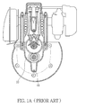
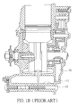
FIGS. 1A and1B , which are diagrams of a lubrication device of four-stroke engines according to claims ofUS 6,213,078 ; wherein, anoil hole 11 in communication withlubricant tank 12 is allocated underneath acam room 10, and the lubricant recycles back to thelubricant tank 12 via theoil hole 11; manipulations of this kind of design at some sloping angles are likely to cause the lubricant to directly reflow to valve via thecam room 10, and then flow out of the engine via a breathing pipe between valve chamber and air filter. - As shown in
FIG. 2 , a lubrication device of four-stroke engines is disclosed according toU.S. Patent No. 6,170,456 , which mainly allocates astirring chamber 14 on a long and narrow concave underneath thecrank case 13, and also forms anoil hole 15 at a bottom of the stirringchamber 14 in communication with an engine oil tank; although this kind of design is capable of preventing massive lubricant from flowing into the crank case when the engine is at a slanting angle, it is not capable of providing other mechanical parts of machine, such as cam and gas valves and others, with effective lubrication when the engine is operationally turning over for a long time period; in addition, the traditional breathing pipe that is externally connecting to air filter generally is not commonly allocated with filter therein, therefore, when the engine is operating at a slanting angle, lubricant is likely to flow out via the breathing pipe, thereby causing problems of unnecessary lubricant consumption and air filter contamination. - Hence, it is a highly urgent issue in the industry for how to provide a lubrication device of four-stroke engines, which is capable of enabling lubricant to flow into valve chamber and cam room to provide effective lubrication, and meanwhile preventing massive lubricant from flowing into air-intake system and thus the cylinder, consequently causing engine extinguished, thereby allowing users to manipulate engine at various angles.
- In view of the disadvantages of the prior art mentioned above, it is a primary objective of the present invention to provide a lubrication device of four-stroke engines, which enables four-stroke engines to be manipulated at various angles.
- It is another objective of the present invention to provide a lubrication device of four-stroke engines, which is capable of providing proper lubrication, and consequently avoiding engine piston jammed in cylinder caused by insufficient lubrication.
- It is a further objective of the present invention to provide a lubrication device of four-stroke engines, which is capable of avoiding problems of lubricant consumption as well as air filter contamination caused by massive lubricant flowing out from breathing pipe.
- To achieve the aforementioned and other objectives, a lubrication device of four-stroke engines is provided according to the present invention; the lubrication device comprises: a lubricant tank, which is connecting to underneath crank case of the engine and is for containing lubricant; a stirring chamber, which is allocated underneath the crank case and partially located inside the lubricant tank, the stirring chamber has at least one oil hole in communication with the lubricant tank; an oil stirring rod, which is allocated at one end of piston connecting rod of the engine and is received in the stirring chamber, the oil stirring rod is for stirring lubricant to oil mists; an oil supply path, the oil supply path consists of a pipeline, which connects rocker arm room and the crank case of the engine, and an oil supply channel, which is allocated inside a crankshaft first section of the crank case and correspondingly connecting the pipeline and interior of the crank case , and when the crankshaft first section rotates to a first rotation angle, the oil supply channel opens to supply the oil mists through the rocker arm room to the cam room of the engine; and an oil recycling path, the oil recycling path has an oil recycling channel, which is allocated inside the crankshaft second section and correspondingly connecting the interiors of the cam room and the crank case, and when the crankshaft second section rotates to a second rotation angle, the oil recycling channel opens to re-absorb the oil mists into the crank case.
- In the foresaid lubrication device of four-stroke engines, the stirring chamber can have a long and narrow concave located inside the lubricant tank, wherein, each of the oil holes is at least located on two sides and bottom end of the long and narrow concave, but not restricted to the stated herein, each of the oil holes can further be located on bottom end of the stirring chamber nearby two sides of the long and narrow concave. In addition, basic principle of the first rotation angle and the second rotation angle is that they are alternating to each other, there is no specific restriction, and in one embodiment, the first rotation angle and the second rotation angle are alternating to each other at an angle of 180 degrees.
- In one embodiment, the oil supply channel can comprises a fist axial aperture, which is connected to the interior of the crank case, and a first radial aperture, which connects the first axial aperture and the pipeline. The said oil supply channel can further comprises a first eccentric aperture, which connects the first axial aperture and the interior of the crank case, and a first airtight oil plug is allocated at axle center of the crankshaft first section corresponding to a rim of the first eccentric aperture. A first obstruction block can be allocated on external side of the crankshaft first section corresponding to the first radial aperture, the first obstruction block can be, for instance, in the form of a half circular ring and is for covering area beyond the first rotation angle.
- Naturally, the oil recycling channel can be accordingly designed and comprises a second axial aperture and a second radial aperture that connects the second axial aperture and the cam room. The said oil recycling channel can further comprises a second eccentric aperture that connects the second axial aperture and the interior of the crank case, and a second airtight oil plug is allocated at axle center of the crankshaft second section corresponding to a rim of the second eccentric aperture. A second obstruction block can be allocated on the crankshaft second section corresponding to the second radial aperture, and the second obstruction block can be, for instance, in the form of a half circular ring and is for covering area beyond the second rotation angle.
- In another embodiment, the oil supply channel can comprise a first slanting aperture that has a first end and a second end, the first end is connecting to the pipeline while the second end is connecting to the interior of the crank case. The said oil supply channel can further comprises a first eccentric aperture that connects the second end and the interior of the crank case, and a first airtight oil plug is allocated at axle center of the crankshaft first section corresponding to a rim of the first eccentric aperture. And a first obstruction block can be allocated on external side of the crankshaft first section corresponding to the first end, the first obstruction block can be, for instance, in the form of a half circular ring and is for covering area beyond the first rotation angle.
- Similarly, the oil recycling channel can also be accordingly designed and comprises a second slanting aperture that has a first end and a second end, the first end is connecting to the cam room while the second end is connecting to the interior of the crank case. The said oil recycling channel further comprises a second eccentric aperture that connects the second end and the interior of the crank case, and a second airtight oil plug is allocated at axle center of the crankshaft second section corresponding to a rim of the second eccentric aperture. And a second obstruction block is allocated on external side of the crankshaft second section corresponding to the first end, the second obstruction structure is, for instance, in the form of a half circular ring and is for covering area beyond the second rotation angle.
- To reach the foresaid objectives, the present invention further provides a lubrication device of four-stroke engines, which is applicable to four-stroke engines that have cylinder, a crank case, a rocker arm room and a cam room that are connecting to each other, and a breathing pipe; the crank case has a crankshaft that is divided into a crankshaft first section, a connection part, and a crankshaft second section; the cylinder has a piston connecting rod therein, and the piston connecting rod is connecting to the connection part; the cam room is allocated with cam that has camshaft; and the lubrication device comprises: a lubricant tank, which is connecting to underneath the crank case and is for containing lubricant; a stirring chamber, which is allocated underneath the crank case and partially located inside the lubricant tank, the stirring chamber has at least one oil hole in communication with the lubricant tank; an oil stirring rod, which is allocated at one end of the piston connecting rod and is set inside the stirring chamber, the oil stirring rod is for stirring lubricant to oil mists; an oil supply path, the oil supply path consists of a pipeline, which connects the rocker arm room and the crank case, and an oil supply channel, which is allocated inside the crankshaft first section correspondingly connecting the pipeline and the interior of the crank case, and when the crankshaft first section rotates to a first rotation angle, the oil supply channel opens to supply the oil mists through the rocker arm room to the cam room; an oil recycling path, the oil recycling path consists of an oil recycling channel, which is allocated on the crankshaft second section correspondingly connecting the interiors of the cam room and the crank case, and when the crankshaft second section rotates to a second rotation angle, the oil recycling channel opens to re-absorb oil mists into the crank case; and an exhaust channel, the exhaust channel consists of a third axial aperture, which is allocated on the camshaft and connecting to the breathing pipe, and a third radial aperture, which connects the third axial aperture and the cam room.
- To reach the foresaid objectives, the present invention further provides a lubrication device of four-stroke engines, which is applicable to four-stroke engines that have cylinder, a crank case, a rocker arm room and a cam room that are connecting to each other, and a breathing pipe; the crank case has a crankshaft that is divided into a crankshaft first section, a connection part, and a crankshaft second section; the cylinder has a piston connecting rod therein, and the piston connecting rod is connecting to the connection part; and the lubrication device comprises: a lubricant tank, which is connecting to underneath the crank case and is for containing lubricant; a stirring chamber, which is allocated underneath the crank case and partially located inside the lubricant tank, the stirring chamber has at least one oil hole in communication with the lubricant tank; an oil stirring rod, which is allocated at one end of the piston connecting rod and is set inside the stirring chamber, the oil stirring rod is for stirring lubricant to oil mists; an oil supply path, the oil supply path consists of a pipeline, which connects the rocker arm room and the crank case, and an oil supply channel, which is allocated inside the crankshaft first section correspondingly connecting the pipeline and the interior of the crank case, and when the crankshaft first section rotates to a first rotation angle, the oil supply channel opens to supply the oil mists through the rocker arm room to the cam room; an oil recycling path, the oil recycling path consists of an oil recycling channel, which is allocated on the crankshaft second section correspondingly connecting the interiors of the cam room and the crank case, and when the crankshaft second section rotates to a second rotation angle, the oil recycling channel opens to re-absorb oil mists into the crank case, wherein the breathing pipe is connected to the space in the four-stroke engine, and the space can be a channel between the cylinder and the crank case.
- Further, the design of the stirring chamber in the foresaid embodiments can be omitted. That is, the lubricant tank is connecting to underneath the crank case for containing lubricant, and the oil stirring rod is allocated at one end of the piston connecting rod corresponding to the stirring chamber for stirring lubricant to oil mists.
- In view of the above, the lubrication device of four-stroke engine of the present invention mainly has the rocker arm room and the crank case connect to each other, and the alternating design of the oil supply and oil-absorption channels enables lubricant mists to cycle from the crank case through the rocker arm room to cam room and then to be re-absorbed into the crank case, thereby allowing engine to be manipulated at various angles; also the design of the oil supply path and the oil recycling path provides proper lubrication, and in accordance with the design of eccentric apertures and airtight oil plugs, situation of excess lubricant flowing out of the crank case can be avoided, thereby avoiding consequent problems of excessive lubricant consumption and engine piston jammed in cylinder caused by insufficient lubrication; in addition, the design of the exhaust channel employs centrifugal force to prevent oil drops or massive oil mists from entering, thereby avoiding problems of lubricant consumption and air filter contamination caused by massive lubricant flowing out through the breathing pipe.
- The present invention can be more fully understood by reading the following detailed description of the preferred embodiments, with reference made to the accompanying drawings, wherein:
-
FIGS. 1A and1B are a top view and a lateral view of a lubrication device of four-stroke engines according to claims ofUS 6,213,078 , respectively; -
FIG. 2 is a top view of a lubrication device of four-stroke engines according to claims ofUS 6,170,456 ; -
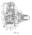
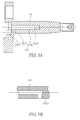
FIGS. 3A and3B are a top view and a lateral view of a lubrication device of four-stroke engines of the present invention, respectively; -
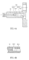
FIGS. 4A and 4B , which respectively illustrate a top view and a local lateral view of a crankshaft first section of four-stroke engines that the present invention is applied to; -
FIGS. 4C and 4D are a magnified diagram of block X and a lateral view of a first obstruction block of the block X ofFIG. 3A , respectively; -
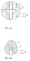
FIGS. 5A and 5B respectively illustrate a top view of a crankshaft second section and a partial lateral view of a four-stroke engine that the present invention is applied to; -
FIGS. 5C and 5D are a magnified diagram of block Y and a lateral view of a second obstruction block of the block Y ofFIG. 3A , respectively; -
FIGS. 6A and 6B are a magnified diagram of block Z and a lateral view of cam and camshaft of the block Z ofFIG. 3A , respectively; -
FIG. 7 illustrates an operation state of the lubrication device of four-stroke engines of the present invention, wherein the engine is turning at 90 degrees; -
FIG. 8 illustrates an operation state of the lubrication device of four-stroke engines of the present invention, wherein the engine is turning at 180 degrees; -
FIG. 9 is a lateral view of oil supply channel of another embodiment of the lubrication device of four-stroke engines of the present invention; and -
FIG. 10 is a lateral view of oil recycling channel of another embodiment of the lubrication device of four-stroke engines of the present invention. -
FIG. 11 is a top view of a breathing pipe in the lubrication device of four-stroke engines according to another embodiment of the present invention; and -
FIG. 12 is a top view of a lubrication device of four-stroke engines according to another embodiment of the present invention. - The following illustrative embodiments are provided to illustrate the disclosure of the present invention, these and other advantages and effects can be apparently understood by those in the art after reading the disclosure of this specification. The present invention can also be performed or applied by other different embodiments. The details of the specification may be on the basis of different points and applications, and numerous modifications and variations can be devised without departing from the spirit of the present invention.
- As shown in
FIGS. 3A and3B , the lubrication device of four-stroke engines of the present invention is applicable to four-stroke engines that at least have acylinder 2, a crankcase 3, arocker arm room 4 and acam room 5 that are connecting to each other, and abreathing pipe 6, thereby enabling lubricant mist to be cycling from thecrank case 3 through therocker arm room 4 to thecam room 5 and then be absorbed back to the crankcase 3, and allowing users to manipulate the engines at various angles. - In the present embodiment, the lubrication device is applied to, for instance, four-stroke engines of wet-sump design, wherein, the crank case and lubricant tank are connecting to each other, but not restrictive of the scope of the present invention, the lubrication device of the present invention is applicable to any four-stroke engine that must integrate with lubrication device.
- In the four-stroke engines of the present embodiment, the crank
case 3 has a crankshaft, the crankshaft is divided into a crankshaftfirst section 32 and a crankshaftsecond section 33 that are connected to each other via aconnection part 31 and move simultaneously; thecylinder 2 consists of apiston connecting rod 21, which is connecting to theconnection part 31, and apiston 22, which is connecting to top end of thepiston connecting rod 21; therocker arm room 4 has arocker arm 41, and thecam room 5 is allocated with acam 51 that has acamshaft 52, also therocker arm 41 is for simultaneously activating thecam 51, in addition, thecam room 5 has abreathing pipe 6 that is for externally connecting to a air filter (not shown in the FIG.) for emitting exhaust fume. Since the principle of internal combustion of four-stroke engines is well understood by those in the industry, and is not a creative feature of the present invention, therefore, descriptions of engine movement principles and detailed mechanism design will not be repeated herein. - The lubrication device of the present invention comprises: a lubricant tank 7, which is integrated to underneath the crank case 3 for containing lubricant 71; a stirring chamber 34, which is allocated beneath the crankshaft 3 and partially located inside the lubricant tank 7, the stirring chamber 34 has at least one oil hole 342 in communication with the lubricant tank 7; an oil stirring rod 23, which is allocated at bottom end of the piston connecting rod 21 and is set inside the stirring chamber 34, the oil stirring rod 23 is for stirring the lubricant 71 to oil mists; an oil supply path, the oil supply path consists of a pipeline 42, which connects the rocker arm room 4 and the crank case 3, and an oil supply channel 321, which is allocated inside the crankshaft first section 32 of the crank case 3 and correspondingly connecting the pipeline 42 and interior of the crank case 3, and when the crankshaft first section 32 is at a first rotation angle, the oil supply channel 321 opens to supply the oil mists through the rocker arm room 4 to the cam room 5; and an oil recycling path, the oil recycling path consists of an oil recycling channel 331, which is allocated inside the crankshaft second section 33 and correspondingly connecting the interiors of the cam room 5 and the crank case 3, and when the crankshaft second section 33 is at a second rotation angle, the oil recycling channel 331 opens to re-absorb the oil mists to the interior of the crank case 3.
- In the present embodiment, the stirring
chamber 34 consists of a long and narrow concave 341 located inside thelubricant tank 7, wherein, in addition to two sides and bottom end of the long and narrow concave 341, each of the oil holes 342 can also be formed on bottom of the stirringchamber 34 nearby the two sides of the long and narrow concave 341, thereby providing engines with proper oil dropping channel at various angles even in a upside down situation, as well as balancing pressure between thecrank case 3 and thelubricant tank 7; the crankshaftfirst section 32 and the crankshaftsecond section 33 are connected to each other via theconnection part 31 and consequently move simultaneously, the basic principle of the said first rotation angle and the said second rotation angle is that they are alternating to each other, but there is no specific restriction; in the present embodiment, the first rotation angle and the second rotation angle are alternating to each other at an angle of 180 degrees as an example, but not restricted to the stated herein. - Please refer to
FIGS. 4A and 4B , theoil supply channel 321 is allocated inside the crankshaftfirst section 32, in the present embodiment, theoil supply channel 321 comprises a firstaxial aperture 3211, which is connecting to interior of thecrank case 3, and a firstradial aperture 3213, which connects the firstaxial aperture 3211 and thepipeline 42; in addition, theoil supply channel 321 further comprises a firsteccentric aperture 3215, which connects the firstaxial aperture 3211 and the interior of thecrank case 3, and a firstairtight oil plug 3217 is allocated at axle center of the crankshaftfirst section 32 corresponding to a rim of the firsteccentric aperture 3215. - In addition, please refer to
FIGS. 4C and 4D , afirst obstruction block 323 is allocated on external side of the crankshaftfirst section 32 corresponding to the firstradial aperture 3213, thefirst obstruction block 323 is in the form of a half circular ring and is for covering area of the firstradial aperture 3213 of the crankshaftfirst section 32 beyond the first rotation angle; one end of theforesaid pipeline 42 is connecting to one side of thecrank case 3 corresponding to the firstradial aperture 3213, namely, space of opposite side of thefirst obstruction block 323, thereby connecting to the firstradial aperture 3213 via the space. - According to the above disclosed design of oil supply path, when the crankshaft
first section 32 is rotating, particles of oil drop are flung off via end side of the crankshaftfirst section 32 by centrifugal force, only oil mists are capable of passing through theoil supply channel 321, in other words, the firstairtight oil plug 3217 mostly encloses exterior of the axle center of the firstaxial aperture 3211, therefore, the particles of oil drops can be flung off via end side of the crankshaftfirst section 32 by centrifugal force while rotating, and pressure difference enables the oil mists to travel only from the firsteccentric aperture 3215 to the firstaxial aperture 3211. - The foresaid first
radial aperture 3213 and thefirst obstruction block 323 compose a supply switch that controls oil supply; in the present invention, when the crankshaftfirst section 32 rotates to the first rotation angle, in other words, the firstradial aperture 3213 is away from territory of thefirst obstruction block 323, and then in accordance with descending route of thepiston 22, a positive pressure generated herein enables the oil mists to travel via thepipeline 42 passing therocker arm room 4 to thecam room 5, thereby reaching objective of oil mists transmission. - Please refer to
FIGS. 5A and 5B , theoil recycling channel 331 is allocated on crankshaftsecond section 33; in the present invention, theoil recycling channel 331 comprises a secondaxial aperture 3311, which is connecting to the interior of thecrank case 3, and a secondradial aperture 3313, which connect the secondaxial aperture 3311 and thecam room 5. In addition, theoil recycling channel 331 further comprises a second eccentric aperture 3315, which are connecting the secondaxial aperture 3311 and the interior of thecrank case 3, and a secondairtight oil plug 3317, which is allocated at the axle center of the crankshaftsecond section 33 corresponding to a rim of the second eccentric aperture 3315, since the secondairtight oil plug 3317 mostly encloses exterior of the axle center of the secondaxial aperture 3311, the particles of oil drops can be flung off via end side of the crankshaftsecond section 33 by centrifugal force while rotating, accordingly, pressure difference prevents the lubricant from traveling to the secondaxial aperture 3311 via the second eccentric aperture 3315. In addition, please refer toFIGS. 5C and 5D , the crankshaftsecond section 33 is allocated with asecond obstruction block 333 corresponding to the secondradial aperture 3313, thesecond obstruction block 333 is, for instance, in the form of a half circular ring and is for covering area of the secondradial aperture 3313 of the crankshaftsecond section 33 beyond the second rotation angle. - According to the above disclosed design of oil recycling path, the second
radial aperture 3313 and thesecond obstruction block 333 compose a re-absorption switch that controls oil mists or oil drops; in the present embodiment, when the crankshaftsecond section 33 rotates to the second rotation angle, in other words, the secondradial aperture 3313 is away from territory of thesecond obstruction block 333, oil mists or oil drops can travel to the interior of thecrank case 3 via the secondradial aperture 3313 and the secondaxial aperture 3311, and in accordance with ascending route of thepiston 22, a negative pressure generated inside the crankcase 3 enables the oil mists to be re-absorbed and recycled. In addition, the second eccentric aperture 3315 is designed to employ centrifugal force for preventing oil drops inside the stirringchamber 34 from reflowing into the secondaxial aperture 3311. It must be specifically stated herein, the first rotation angle and the second rotation angle of the present embodiment are alternating to each other at an angle of 180 degrees as an example; in other words, when the crankshaftfirst section 32 rotates to the first rotation angle, the crankshaftsecond section 33 is at an angle 180 difference from the first rotation angle; therefore, theoil supply channel 321 and theoil recycling channel 331 open alternately, but not at the same time. - Moreover, although the crankshaft of the
crank case 3 of the present embodiment consists of a crankshaftfirst section 32 and a crankshaftsecond section 33 that are connecting to each other via a connectingpart 33 and moving simultaneously thus, it is not restrictive of the scope of the present invention; the said crankshaft can also be replaced with a single crankshaft, naturally, the single crankshaft can be divided into a first section, connection part, and a second section, and then form the foresaidoil supply channel 321 andoil recycling channel 331 on the first section and the second section respectively to achieve the same technique effect; since allocation of a single piece crankshaft or two pieces fabricated crankshaft that move simultaneously inside crank case of engine is commonly adopted technique by the industry, but not creative feature of the present invention, it has no need of detailed descriptions with illustrations herein. - The
cam room 5 has acam 51 allocated therein, thecam 51 and acam gear 53 are fixed on acamshaft 52, and thecam gear 53 is activated by acrankshaft gear 335 that is fixed on the crankshaftsecond section 33. Besides, thecamshaft 52 is allocated with anexhaust channel 521 in order to connect thecam room 5 and thebreathing pipe 6, and thebreathing pipe 6 is for connecting to air filter, not shown in the FIG. Please refer toFIGS. 6A and 6B , in the present embodiment, theexhaust channel 521 comprises a thirdaxial aperture 5211, which is allocated on thecamshaft 52 and is connecting to thebreathing pipebreathing pipe 6, and a thirdradial aperture 5213, which connects the thirdaxial aperture 5211 and thecam room 5. Since the rotation of thecam 51 and thecamshaft 52 enables the thirdradial aperture 5213 to create fling centrifugal force, neither particles of oil drops nor massive oil mists will travel through the exhaust channel into the air filter while engine is operating. - When the engine is operating in a level state, as shown in
FIGS. 3A ,4A through 4D , and5A through 5D , thelubricant 71 capable of entering into the crankcase 3 throughoil holes 342 located on bottom of the long and narrow concave 341 underneath the crankcase 3, and when the crankshaft, including the crankshaftfirst section 32 and crankshaftsecond section 33, is rotating, it simultaneously activates theoil stirring rod 23 at bottom end of thepiston connecting rod 21 to stir lubricant inside the long and narrow concave 341 to form oil drops and oil mists, the oil drops and oil mists can be dispensed evenly inside space of thecrank case 3, and the oil holes on two sides of the long and narrow concave 341 is capable of balancing interior pressures of thecrank case 3 andlubricant tank 7. - When the crankshaft, including the crankshaft first section 32 and crankshaft second section 33 rotates counterclockwise to the first rotation angle, it enables the piston connecting rod 21 to descend, and consequently the interior pressure of the crank case 3 begins to increase due to reduced volume, thereby forcing oil mists inside the crank case 3 to travel into the oil supply channel 321 inside the crankshaft first section 32, and then through the first eccentric aperture 3215 and the first axial aperture 3211 to the first radial aperture 3213, at this moment, the relation between the first radial aperture 3213 and the first obstruction block 323 is in an opening state, the first obstruction block 323 is opposite to an opening space in communication with the pipeline 42, therefore the oil mists are capable of traveling into the pipeline 42, and then the oil mists can travel to the rocker arm room 4 through the pipeline 42 to lubricate the rocker arm 41 and other components, as well as travel to the cam room 5 to lubricate the cam 51, cam gear 53, and crankshaft gear 335; the design of the third radial aperture 5213 of the exhaust channel 521 employs centrifugal force to prevent massive oil mists from entering the air filter, and congealed liquid lubricant and oil mists are gathered underneath the cam room 5; at this moment, relation between the second radial aperture 3313 of the crankshaft second section 33 and the second obstruction block 333 is in a closing state.
- When the
piston 22 of thecylinder 2 descends to a dead end, thepiston 22 is back on an ascending route, and then the firstradial aperture 3213 of the crankshaftfirst section 32 and thefirst obstruction block 323 is in a closing state, while the secondradial aperture 3313 of the crankshaftsecond section 33 and thesecond obstruction block 333 is in an opening state, and then the interior pressure of thecrank case 3 begins to decrease due to expanded volume, therefore, via the secondradial aperture 3313 of the crankshaftsecond section 33 and then passing through the secondaxial aperture 3311 and the second eccentric aperture 3315, the gathered lubricant and oil mists underneath thecam room 5 are absorbed into the crankcase 3, and a lubrication cycle is completed thus. - As shown in
FIG. 7 , when the engine is manipulated at a 90 degree angle, lubricant dispersion is affected by gravity, lubrication can be done by utilizing lubricant originally stored inside the long and narrow concave 341 of thecrank case 3, and oil drops can be continuously provided to the crankshaftfirst section 32 via oil holes 342 on bottom of the stirringchamber 34 nearby two sides of the long and narrow concave 341, and then the oil drops are cracked into oil mists by rotating the crankshaftfirst section 32 for lubrication purpose; and in order to prevent excess lubricant from entering therocker arm room 4,cam room 5, and air filter and consequent excessive lubrication or dead engine; the design of theoil supply channel 321, which employs centrifugal force as well as auto control over opening/closing, provides the lubrication device of the present invention with capability that allows oil mists to pass through but secludes the oil drops of larger particles from passing through, thereby effectively avoiding excessive lubrication; and the design of theoil recycling channel 331 provides the lubrication device of the present invention with capability that separates lubricant received in thecrank case 3 from re-absorbed lubricant received in thecam room 5. - As shown in
FIG. 8 , when the engine is manipulated at 180 degree angle, the lubrication principle and path are the same as in the foresaid engine turning at 90 degree; in both situation, lubrication can be done by utilizing lubricant originally stored inside the long and narrow concave 341 of thecrank case 3, and oil drops can be continuously provided to the crankshaftfirst section 32 via oil holes 342 on bottom of the stirringchamber 34 nearby two sides of the long and narrow concave 341, therefore, there is no need of repetitive detailed descriptions herein. According to the above disclosed descriptions, the lubrication device of the present invention is capable of providing proper lubrication and allowing engines to be manipulated normally at various angles. - In addition, although in the present embodiment, the
oil supply channel 321 mainly comprises a firstaxial aperture 3211 allocated on a crankshaftfirst section 32 and a firstradial aperture 3213, and theoil recycling channel 331 mainly comprises a secondaxial aperture 3311 allocated on a crankshaftsecond section 33 and a secondradial aperture 3313, but this example is not restrictive of the scope of the present invention. For instance, as shown inFIG. 9 , the firstaxial aperture 3211 and the firstradial aperture 3213 of the crankshaftfirst section 32 can be replaced by a first slanting aperture 3212 that has a first end and a second end, plainly, the first end is connecting to the pipeline, and the second end is connecting to interior of the crank case, and designs of the first eccentric aperture and the first obstruction block are the same as in the previous embodiment, there is no need of repetitive descriptions herein. Similarly, as shown inFIG. 10 , the secondaxial aperture 3311 and the secondradial aperture 3313 of the crankshaftsecond section 33 can be replaced by asecond slanting aperture 3312 that has a first end and a second end, plainly, the first end is connecting to cam room, and the second end is connecting to interior of crank case, and designs of the second eccentric aperture and the second obstruction block are also the same as in the previous embodiment, there is no need of repetitive description herein. - The
exhaust channel 521 is disposed in thecam room 5 for avoiding problems, such as massive lubricant flowing out from thebreathing pipe 6, and consequent massive lubricant consumption, air filter contamination and engine extinguished resulting from massive lubricant accumulated in the breathing pipe. The positions of theexhaust channel 521 and thebreathing pipe 6 are not limited by the foresaid embodiments. The position of thebreathing pipe 6 can be optionally designed in the four-stroke engine depending upon demand of practical application. As shown inFIG. 11 , thebreathing pipe 6 is connected to a room space, which is not the space in thecam room 5 shown inFIG. 3A , in the four-stroke engine. Specifically, thebreathing pipe 6 is connected to thechannel 61 between thecylinder 2 and the crankcase 3. The remaining designs inFIG. 11 are similar to those inFIG. 3A . Since thebreathing pipebreathing pipe 6 is not hermetically connected to thecamshaft 52, there is no fling centrifugal force generated from the rotation of thecam 51 and thecamshaft 52. Therefore, this embodiment can be used in the engine generating fine oil drops or little oil mists during non-long term of manipulation, such that air smoothly flows into thechannel 61 and lubricant is prevented from flowing out of thebreathing pipebreathing pipe 6. In addition, in this embodiment, the lubrication device of the four-stroke engine can be designed without theoil supply channel 321 and theoil recycling channel 331; that is, only theexhaust channel 521 is designed instead in the lubrication device. -
FIG. 12 shows anther embodiment of a lubrication device of a four-stroke engine in the present invention. The four-stroke engine includes acylinder 2, a crankcase 3, arocker arm room 4 and acam room 5 that are connecting to each other, and abreathing pipe 6, thereby enabling lubricant mist to be cycling from thecrank case 3 through therocker arm room 4 to thecam room 5 and then be absorbed back to the crankcase 3, and allowing users to manipulate the engines at various angles. This embodiment differs from that shown inFIG. 3A in that thelubricant tank 7 and the stirringchamber 34 are integrally formed. That is, thelubricant tank 7 is not hermetical, such that lubricant is not isolated in the stirringchamber 34. Also, theoil stirring rod 23 is directly formed on one end of thepiston connecting rod 21 corresponding to thelubricant tank 7 for directly stirring the lubricant to oil mists. Thus, this embodiment is suitable for machines manipulated at smaller angles such as lawn mowers. The designs of the oil supply channel, oil recycling channel, eccentric aperture and airtight oil plug are similar to those in the foresaid embodiments, and there is no need to repetitive description herein. In this embodiment, thebreathing pipe 6 is disposed in thecam room 5. Alternatively, thebreathing pipe 6 can be disposed in the space connecting thecam room 5 and therocker arm room 4, or disposed in thechannel 61 between thecylinder 2 and the crankcase 3. - In addition, in this embodiment, the lubrication device of the four-stroke engine can be designed without the
oil supply channel 321 and theoil recycling channel 331; that is, only theexhaust channel 521 is designed instead in the lubrication device. - In view of the above, the lubrication device of four-stroke engines of the present invention mainly has the rocker arm room and the crank case connecting to each other, and the design of alternating oil supply and oil-absorption channels enables lubricant mists to cycle from the crank case through the rocker arm room to cam room and then to be re-absorbed into the crank case, thereby allowing engine to be manipulated at various angles; also the design of the oil supply path and the oil recycling path provides proper lubrication, and in accordance with the design of eccentric apertures and airtight oil plugs, situation of excess lubricant flowing out of the crank case can be avoided; in addition, the design of the exhaust channel employs centrifugal force to prevent oil drops or massive oil mists from entering, thereby avoiding problems of excessive lubricant consumption and air filter contamination caused by massive lubricant flowing out through the breathing pipe. Therefore, the lubrication device of four-stroke engines provided by the present invention overcomes various drawbacks of the prior art, and conform to patent application elements: industrial applicability, novelty, and non-obviousness.
- The foregoing descriptions of the detailed embodiments are only illustrated to disclose the features and functions of the present invention and not restrictive of the scope of the present invention. It should be understood to those in the art that all modifications and variations according to the spirit and principle in the disclosure of the present invention should fall within the scope of the appended claims.
Claims (16)
- A lubrication device of a four-stroke engine, wherein the four-stroke engine has a cylinder, a crank case, a rocker arm room and a cam room connected to the rocker arm room, the cylinder having a piston connecting rod connected to a connection part, the lubrication device comprising:a lubricant tank connected to a bottom of the crank case for containing lubricant;a stirring chamber allocated beneath the crank case and partially located inside the lubricant tank, the stirring chamber having at least one oil hole in communication with the lubricant tank;an oil stirring rod allocated at one end of the piston connecting rod and received in the stirring chamber for stirring lubricant to oil mists; anda breathing pipe disposed in a space in the engine for emitting exhaust fume.
- The lubrication device of four-stroke engines of claim 1, wherein the stirring chamber has a long and narrow concave disposed in the lubricant tank, and each of the oil holes is allocated on at least on two sides and a bottom end of the long and narrow concave.
- The lubrication device of four-stroke engines of claim 2, wherein each of the oil holes is further allocated on a bottom end of the stirring chamber nearby the two sides of the long and narrow concave.
- The lubrication device of four-stroke engine of claim 1, wherein the first rotation angle and the second rotation angle are alternating to each other, and the first rotation angle and the second rotation angle are alternating to each other at 180 degrees.
- The lubrication device of four-stroke engines of claim 1, wherein the crank case having a crankshaft divided into a crankshaft first section and a crankshaft second that are connected via a connection part, and lubrication device further comprises:an oil supply path having a pipeline connected to the rocker arm room and the crank case, and an oil supply channel allocated inside the crankshaft first section and correspondingly connected to the pipeline and interior of the crank case, the oil supply channel being open when the crankshaft first section rotates to a first rotation angle, so as to supply the oil mists through the rocker arm room to the cam room; andan oil recycling path including an oil recycling channel allocated inside the crankshaft second section and correspondingly connected to the interiors of the cam room and the crank case, the oil recycling channel being open when the crankshaft second section rotates to a second rotation angle different from the first rotation angle, so as to re-absorb the oil mists into the crank case.
- The lubrication device of four-stroke engines of claim 5, wherein the oil supply channel comprises a first axial aperture connected to interior of the crank case, a first radial aperture connected to the first axial aperture and the pipeline, a first eccentric aperture connected to the first axial aperture and interior of the crank case, and a first airtight oil plug allocated at an axle center of the crankshaft first section corresponding to a rim of the first eccentric aperture.
- The lubrication device of four-stroke engines of claim 5, further comprising a first obstruction block allocated on an external side of the crankshaft first section corresponding to the first radial aperture for covering an area beyond the first rotation angle, and the first obstruction block is in the form of a half circular ring.
- The lubrication device of four-stroke engines of claim 5, wherein the oil recycling channel comprises a second axial aperture connected to the interior of the crank case, a second radial aperture connected to the second axial aperture and the cam room, a second eccentric aperture connected to the second axial aperture and the interior of the crank case, and a second airtight oil plug allocated at axle center of the crankshaft second section corresponding to a rim of the second eccentric aperture.
- The lubrication device of four-stroke engines of claim 8, further comprising a second obstruction block allocated on an external side of the crankshaft second section corresponding to the second radial aperture, for covering an area beyond the second rotation angle, and the second obstruction block is in the form of a half circular ring.
- The lubrication device of four-stroke engines of claim 5, wherein the oil supply channel comprises:a first slanting aperture, the first slanting aperture having a first end connected to the pipeline, and a second end connected to interior of the crank case; anda first eccentric aperture connected to the second end and the interior of the crank case, and a first airtight oil plug allocated at an axle center of the crankshaft first section corresponding to a rim of the first eccentric aperture, wherein a first obstruction block is allocated on an external side of the crankshaft first section corresponding to the first end for covering an area beyond the first rotation angle.
- The lubrication device of four-stroke engines of claim 5, wherein the oil recycling channel comprises:a second slanting aperture, the second slanting aperture having a first end connected to the cam room, and a second end connected to interior of the crank case; anda second eccentric aperture connected to the second end and the interior of the crank case, and a second airtight oil plug allocated at an axle center of the crankshaft second section corresponding to a rim of the second eccentric aperture, wherein a second obstruction block is allocated on an external side of the crankshaft second section corresponding to the first end for covering an area beyond the second rotation angle.
- The lubrication device of four-stroke engines of claim 1, wherein the cam room is provided with a cam having a camshaft, and the lubrication device comprises an exhaust channel having a third axial aperture allocated on the camshaft and connected to the breathing pipe, and a third radial aperture connected to the third axial aperture and the cam room.
- The lubrication device of four-stroke engines of claim 12, wherein the third radial aperture is vertical to the third axial aperture.
- The lubrication device of four-stroke engines of claim 1, wherein the breathing pipe is disposed in a space connecting the rocker arm room and the cam room.
- The lubrication device of four-stroke engines of claim 1, wherein the breathing pipe is disposed in a channel between the cylinder and the crankshaft box.
- The lubrication device of four-stroke engines of claim 1, wherein the lubricant tank and the stirring chamber is integrally formed without isolating the lubricant.
Applications Claiming Priority (2)
| Application Number | Priority Date | Filing Date | Title |
|---|---|---|---|
| TW96137017 | 2007-10-03 | ||
| TW097137665A TWI322221B (en) | 2007-10-03 | 2008-10-01 | Lubricating device for four-stroke engine |
Publications (2)
| Publication Number | Publication Date |
|---|---|
| EP2045449A1 true EP2045449A1 (en) | 2009-04-08 |
| EP2045449B1 EP2045449B1 (en) | 2011-12-14 |
Family
ID=40089978
Family Applications (1)
| Application Number | Title | Priority Date | Filing Date |
|---|---|---|---|
| EP08017381A Active EP2045449B1 (en) | 2007-10-03 | 2008-10-02 | Lubrication device of four-stroke engines |
Country Status (4)
| Country | Link |
|---|---|
| EP (1) | EP2045449B1 (en) |
| JP (1) | JP4796111B2 (en) |
| AT (1) | ATE537335T1 (en) |
| TW (1) | TWI322221B (en) |
Cited By (2)
| Publication number | Priority date | Publication date | Assignee | Title |
|---|---|---|---|---|
| CN114458412A (en) * | 2022-01-26 | 2022-05-10 | 浙江亚特电器股份有限公司 | A stir oily structure and engine for engine |
| CN115434782A (en) * | 2022-09-27 | 2022-12-06 | 山东金奥机械有限公司 | Lubricating device of four-stroke engine |
Families Citing this family (1)
| Publication number | Priority date | Publication date | Assignee | Title |
|---|---|---|---|---|
| CN104763524A (en) * | 2015-03-27 | 2015-07-08 | 山东华盛农业药械有限责任公司 | Small air-cooled four-stroke gasoline engine |
Citations (5)
| Publication number | Priority date | Publication date | Assignee | Title |
|---|---|---|---|---|
| GB435146A (en) * | 1934-05-14 | 1935-09-16 | Alfred Prestwich John | Improvements in and relating to the lubrication of internal-combustion engines, compressors and the like |
| EP0779412A2 (en) * | 1995-12-15 | 1997-06-18 | Honda Giken Kogyo Kabushiki Kaisha | Lubricating system in a 4-cycle engine |
| US6170456B1 (en) | 1998-12-31 | 2001-01-09 | Industrial Technology Research Institute | Lubricating device for four-stroke engine |
| US6202613B1 (en) * | 1998-09-01 | 2001-03-20 | Kioritz Corporation | Four-stroke cycle internal combustion engine |
| US6283084B1 (en) * | 1999-04-19 | 2001-09-04 | Kioritz Corporation | Four-stroke cycle internal combustion engine |
Family Cites Families (4)
| Publication number | Priority date | Publication date | Assignee | Title |
|---|---|---|---|---|
| JPH06299830A (en) * | 1993-02-17 | 1994-10-25 | Ishikawajima Shibaura Mach Co Ltd | Lubricating device of four-cycle engine |
| JP3975046B2 (en) * | 2000-03-14 | 2007-09-12 | 本田技研工業株式会社 | Handheld four-cycle engine |
| JP3388229B2 (en) * | 2000-12-25 | 2003-03-17 | 本田技研工業株式会社 | Lubrication system for four-stroke engine |
| JP3701946B2 (en) * | 2003-01-14 | 2005-10-05 | 川崎重工業株式会社 | 4-cycle engine |
-
2008
- 2008-10-01 TW TW097137665A patent/TWI322221B/en active
- 2008-10-02 AT AT08017381T patent/ATE537335T1/en active
- 2008-10-02 EP EP08017381A patent/EP2045449B1/en active Active
- 2008-10-03 JP JP2008258947A patent/JP4796111B2/en active Active
Patent Citations (6)
| Publication number | Priority date | Publication date | Assignee | Title |
|---|---|---|---|---|
| GB435146A (en) * | 1934-05-14 | 1935-09-16 | Alfred Prestwich John | Improvements in and relating to the lubrication of internal-combustion engines, compressors and the like |
| EP0779412A2 (en) * | 1995-12-15 | 1997-06-18 | Honda Giken Kogyo Kabushiki Kaisha | Lubricating system in a 4-cycle engine |
| US6213078B1 (en) | 1995-12-15 | 2001-04-10 | Honda Giken Kogyo Kabushiki Kaisha | Lubricating system in a 4-cycle engine |
| US6202613B1 (en) * | 1998-09-01 | 2001-03-20 | Kioritz Corporation | Four-stroke cycle internal combustion engine |
| US6170456B1 (en) | 1998-12-31 | 2001-01-09 | Industrial Technology Research Institute | Lubricating device for four-stroke engine |
| US6283084B1 (en) * | 1999-04-19 | 2001-09-04 | Kioritz Corporation | Four-stroke cycle internal combustion engine |
Cited By (3)
| Publication number | Priority date | Publication date | Assignee | Title |
|---|---|---|---|---|
| CN114458412A (en) * | 2022-01-26 | 2022-05-10 | 浙江亚特电器股份有限公司 | A stir oily structure and engine for engine |
| CN114458412B (en) * | 2022-01-26 | 2023-10-17 | 浙江亚特电器股份有限公司 | A stir oily structure and engine for engine |
| CN115434782A (en) * | 2022-09-27 | 2022-12-06 | 山东金奥机械有限公司 | Lubricating device of four-stroke engine |
Also Published As
| Publication number | Publication date |
|---|---|
| ATE537335T1 (en) | 2011-12-15 |
| JP4796111B2 (en) | 2011-10-19 |
| TWI322221B (en) | 2010-03-21 |
| JP2009092066A (en) | 2009-04-30 |
| EP2045449B1 (en) | 2011-12-14 |
| TW200916644A (en) | 2009-04-16 |
Similar Documents
| Publication | Publication Date | Title |
|---|---|---|
| US7584736B2 (en) | Lubrication device of four-stroke engines | |
| RU2526610C2 (en) | Four-stroke lubrication system | |
| CA2340578C (en) | Handheld type four-cycle engine | |
| EP1288454B1 (en) | System for lubricating valve-operating mechanism in engine | |
| CN101413412B (en) | Lubricating device for four-stroke engine | |
| US5947068A (en) | Four-stroke cycle internal combustion engine | |
| US7481197B1 (en) | Lubrication device of four-stroke engines | |
| EP2045449B1 (en) | Lubrication device of four-stroke engines | |
| JP3894723B2 (en) | Engine head cover structure | |
| CA2341289C (en) | Oil mist generation system in handheld type four-cycle engine | |
| KR20020034932A (en) | Engine valve operation mechanism | |
| EP1186750B1 (en) | Valve-operating mechanism in 4-cycle engine | |
| US20090272360A1 (en) | Lubrication device of four-stroke engines | |
| JP4371563B2 (en) | Engine valve mechanism | |
| JP4661862B2 (en) | Oil supply structure for internal combustion engine | |
| JPH06299830A (en) | Lubricating device of four-cycle engine | |
| JP4394819B2 (en) | Lubricating device for timing gears in handheld engines | |
| JP3854050B2 (en) | Four-cycle engine lubrication system | |
| JP3881830B2 (en) | Valve mechanism of handheld four-cycle engine | |
| JP4458727B2 (en) | Breather device for handheld four-cycle engine | |
| JP4015389B2 (en) | Engine valve mechanism lubrication system | |
| EP1201882A1 (en) | Engine valve operation mechanism | |
| JP3881831B2 (en) | Four cycle engine | |
| JP3819690B2 (en) | Four cycle engine | |
| JP3854049B2 (en) | Four cycle engine |
Legal Events
| Date | Code | Title | Description |
|---|---|---|---|
| PUAI | Public reference made under article 153(3) epc to a published international application that has entered the european phase |
Free format text: ORIGINAL CODE: 0009012 |
|
| AK | Designated contracting states |
Kind code of ref document: A1 Designated state(s): AT BE BG CH CY CZ DE DK EE ES FI FR GB GR HR HU IE IS IT LI LT LU LV MC MT NL NO PL PT RO SE SI SK TR |
|
| AX | Request for extension of the european patent |
Extension state: AL BA MK RS |
|
| 17P | Request for examination filed |
Effective date: 20090714 |
|
| AKX | Designation fees paid |
Designated state(s): AT BE BG CH CY CZ DE DK EE ES FI FR GB GR HR HU IE IS IT LI LT LU LV MC MT NL NO PL PT RO SE SI SK TR |
|
| 17Q | First examination report despatched |
Effective date: 20091201 |
|
| GRAP | Despatch of communication of intention to grant a patent |
Free format text: ORIGINAL CODE: EPIDOSNIGR1 |
|
| GRAS | Grant fee paid |
Free format text: ORIGINAL CODE: EPIDOSNIGR3 |
|
| GRAA | (expected) grant |
Free format text: ORIGINAL CODE: 0009210 |
|
| AK | Designated contracting states |
Kind code of ref document: B1 Designated state(s): AT BE BG CH CY CZ DE DK EE ES FI FR GB GR HR HU IE IS IT LI LT LU LV MC MT NL NO PL PT RO SE SI SK TR |
|
| REG | Reference to a national code |
Ref country code: GB Ref legal event code: FG4D |
|
| REG | Reference to a national code |
Ref country code: CH Ref legal event code: EP |
|
| REG | Reference to a national code |
Ref country code: IE Ref legal event code: FG4D |
|
| REG | Reference to a national code |
Ref country code: DE Ref legal event code: R096 Ref document number: 602008011909 Country of ref document: DE Effective date: 20120209 |
|
| REG | Reference to a national code |
Ref country code: SE Ref legal event code: TRGR |
|
| REG | Reference to a national code |
Ref country code: NL Ref legal event code: VDEP Effective date: 20111214 |
|
| PG25 | Lapsed in a contracting state [announced via postgrant information from national office to epo] |
Ref country code: LT Free format text: LAPSE BECAUSE OF FAILURE TO SUBMIT A TRANSLATION OF THE DESCRIPTION OR TO PAY THE FEE WITHIN THE PRESCRIBED TIME-LIMIT Effective date: 20111214 Ref country code: NO Free format text: LAPSE BECAUSE OF FAILURE TO SUBMIT A TRANSLATION OF THE DESCRIPTION OR TO PAY THE FEE WITHIN THE PRESCRIBED TIME-LIMIT Effective date: 20120314 |
|
| LTIE | Lt: invalidation of european patent or patent extension |
Effective date: 20111214 |
|
| PG25 | Lapsed in a contracting state [announced via postgrant information from national office to epo] |
Ref country code: HR Free format text: LAPSE BECAUSE OF FAILURE TO SUBMIT A TRANSLATION OF THE DESCRIPTION OR TO PAY THE FEE WITHIN THE PRESCRIBED TIME-LIMIT Effective date: 20111214 Ref country code: SI Free format text: LAPSE BECAUSE OF FAILURE TO SUBMIT A TRANSLATION OF THE DESCRIPTION OR TO PAY THE FEE WITHIN THE PRESCRIBED TIME-LIMIT Effective date: 20111214 Ref country code: NL Free format text: LAPSE BECAUSE OF FAILURE TO SUBMIT A TRANSLATION OF THE DESCRIPTION OR TO PAY THE FEE WITHIN THE PRESCRIBED TIME-LIMIT Effective date: 20111214 Ref country code: LV Free format text: LAPSE BECAUSE OF FAILURE TO SUBMIT A TRANSLATION OF THE DESCRIPTION OR TO PAY THE FEE WITHIN THE PRESCRIBED TIME-LIMIT Effective date: 20111214 Ref country code: GR Free format text: LAPSE BECAUSE OF FAILURE TO SUBMIT A TRANSLATION OF THE DESCRIPTION OR TO PAY THE FEE WITHIN THE PRESCRIBED TIME-LIMIT Effective date: 20120315 |
|
| PG25 | Lapsed in a contracting state [announced via postgrant information from national office to epo] |
Ref country code: CY Free format text: LAPSE BECAUSE OF FAILURE TO SUBMIT A TRANSLATION OF THE DESCRIPTION OR TO PAY THE FEE WITHIN THE PRESCRIBED TIME-LIMIT Effective date: 20111214 Ref country code: BE Free format text: LAPSE BECAUSE OF FAILURE TO SUBMIT A TRANSLATION OF THE DESCRIPTION OR TO PAY THE FEE WITHIN THE PRESCRIBED TIME-LIMIT Effective date: 20111214 |
|
| PG25 | Lapsed in a contracting state [announced via postgrant information from national office to epo] |
Ref country code: SK Free format text: LAPSE BECAUSE OF FAILURE TO SUBMIT A TRANSLATION OF THE DESCRIPTION OR TO PAY THE FEE WITHIN THE PRESCRIBED TIME-LIMIT Effective date: 20111214 Ref country code: EE Free format text: LAPSE BECAUSE OF FAILURE TO SUBMIT A TRANSLATION OF THE DESCRIPTION OR TO PAY THE FEE WITHIN THE PRESCRIBED TIME-LIMIT Effective date: 20111214 Ref country code: IS Free format text: LAPSE BECAUSE OF FAILURE TO SUBMIT A TRANSLATION OF THE DESCRIPTION OR TO PAY THE FEE WITHIN THE PRESCRIBED TIME-LIMIT Effective date: 20120414 Ref country code: CZ Free format text: LAPSE BECAUSE OF FAILURE TO SUBMIT A TRANSLATION OF THE DESCRIPTION OR TO PAY THE FEE WITHIN THE PRESCRIBED TIME-LIMIT Effective date: 20111214 Ref country code: BG Free format text: LAPSE BECAUSE OF FAILURE TO SUBMIT A TRANSLATION OF THE DESCRIPTION OR TO PAY THE FEE WITHIN THE PRESCRIBED TIME-LIMIT Effective date: 20120314 |
|
| PG25 | Lapsed in a contracting state [announced via postgrant information from national office to epo] |
Ref country code: PT Free format text: LAPSE BECAUSE OF FAILURE TO SUBMIT A TRANSLATION OF THE DESCRIPTION OR TO PAY THE FEE WITHIN THE PRESCRIBED TIME-LIMIT Effective date: 20120416 Ref country code: RO Free format text: LAPSE BECAUSE OF FAILURE TO SUBMIT A TRANSLATION OF THE DESCRIPTION OR TO PAY THE FEE WITHIN THE PRESCRIBED TIME-LIMIT Effective date: 20111214 Ref country code: PL Free format text: LAPSE BECAUSE OF FAILURE TO SUBMIT A TRANSLATION OF THE DESCRIPTION OR TO PAY THE FEE WITHIN THE PRESCRIBED TIME-LIMIT Effective date: 20111214 |
|
| REG | Reference to a national code |
Ref country code: AT Ref legal event code: MK05 Ref document number: 537335 Country of ref document: AT Kind code of ref document: T Effective date: 20111214 |
|
| PLBE | No opposition filed within time limit |
Free format text: ORIGINAL CODE: 0009261 |
|
| STAA | Information on the status of an ep patent application or granted ep patent |
Free format text: STATUS: NO OPPOSITION FILED WITHIN TIME LIMIT |
|
| PG25 | Lapsed in a contracting state [announced via postgrant information from national office to epo] |
Ref country code: DK Free format text: LAPSE BECAUSE OF FAILURE TO SUBMIT A TRANSLATION OF THE DESCRIPTION OR TO PAY THE FEE WITHIN THE PRESCRIBED TIME-LIMIT Effective date: 20111214 |
|
| 26N | No opposition filed |
Effective date: 20120917 |
|
| REG | Reference to a national code |
Ref country code: DE Ref legal event code: R097 Ref document number: 602008011909 Country of ref document: DE Effective date: 20120917 |
|
| PG25 | Lapsed in a contracting state [announced via postgrant information from national office to epo] |
Ref country code: AT Free format text: LAPSE BECAUSE OF FAILURE TO SUBMIT A TRANSLATION OF THE DESCRIPTION OR TO PAY THE FEE WITHIN THE PRESCRIBED TIME-LIMIT Effective date: 20111214 |
|
| PG25 | Lapsed in a contracting state [announced via postgrant information from national office to epo] |
Ref country code: ES Free format text: LAPSE BECAUSE OF FAILURE TO SUBMIT A TRANSLATION OF THE DESCRIPTION OR TO PAY THE FEE WITHIN THE PRESCRIBED TIME-LIMIT Effective date: 20120325 |
|
| PG25 | Lapsed in a contracting state [announced via postgrant information from national office to epo] |
Ref country code: MC Free format text: LAPSE BECAUSE OF NON-PAYMENT OF DUE FEES Effective date: 20121031 |
|
| REG | Reference to a national code |
Ref country code: CH Ref legal event code: PL |
|
| PG25 | Lapsed in a contracting state [announced via postgrant information from national office to epo] |
Ref country code: FI Free format text: LAPSE BECAUSE OF FAILURE TO SUBMIT A TRANSLATION OF THE DESCRIPTION OR TO PAY THE FEE WITHIN THE PRESCRIBED TIME-LIMIT Effective date: 20111214 |
|
| REG | Reference to a national code |
Ref country code: IE Ref legal event code: MM4A |
|
| PG25 | Lapsed in a contracting state [announced via postgrant information from national office to epo] |
Ref country code: IE Free format text: LAPSE BECAUSE OF NON-PAYMENT OF DUE FEES Effective date: 20121002 Ref country code: CH Free format text: LAPSE BECAUSE OF NON-PAYMENT OF DUE FEES Effective date: 20121031 Ref country code: LI Free format text: LAPSE BECAUSE OF NON-PAYMENT OF DUE FEES Effective date: 20121031 |
|
| PG25 | Lapsed in a contracting state [announced via postgrant information from national office to epo] |
Ref country code: MT Free format text: LAPSE BECAUSE OF FAILURE TO SUBMIT A TRANSLATION OF THE DESCRIPTION OR TO PAY THE FEE WITHIN THE PRESCRIBED TIME-LIMIT Effective date: 20111214 |
|
| PG25 | Lapsed in a contracting state [announced via postgrant information from national office to epo] |
Ref country code: TR Free format text: LAPSE BECAUSE OF FAILURE TO SUBMIT A TRANSLATION OF THE DESCRIPTION OR TO PAY THE FEE WITHIN THE PRESCRIBED TIME-LIMIT Effective date: 20111214 |
|
| PG25 | Lapsed in a contracting state [announced via postgrant information from national office to epo] |
Ref country code: LU Free format text: LAPSE BECAUSE OF NON-PAYMENT OF DUE FEES Effective date: 20121002 |
|
| PG25 | Lapsed in a contracting state [announced via postgrant information from national office to epo] |
Ref country code: HU Free format text: LAPSE BECAUSE OF FAILURE TO SUBMIT A TRANSLATION OF THE DESCRIPTION OR TO PAY THE FEE WITHIN THE PRESCRIBED TIME-LIMIT Effective date: 20081002 |
|
| REG | Reference to a national code |
Ref country code: FR Ref legal event code: PLFP Year of fee payment: 8 |
|
| REG | Reference to a national code |
Ref country code: FR Ref legal event code: PLFP Year of fee payment: 9 |
|
| REG | Reference to a national code |
Ref country code: FR Ref legal event code: PLFP Year of fee payment: 10 |
|
| REG | Reference to a national code |
Ref country code: FR Ref legal event code: PLFP Year of fee payment: 11 |
|
| PGFP | Annual fee paid to national office [announced via postgrant information from national office to epo] |
Ref country code: DE Payment date: 20251029 Year of fee payment: 18 |
|
| PGFP | Annual fee paid to national office [announced via postgrant information from national office to epo] |
Ref country code: GB Payment date: 20251027 Year of fee payment: 18 |
|
| PGFP | Annual fee paid to national office [announced via postgrant information from national office to epo] |
Ref country code: IT Payment date: 20251021 Year of fee payment: 18 |
|
| PGFP | Annual fee paid to national office [announced via postgrant information from national office to epo] |
Ref country code: FR Payment date: 20251027 Year of fee payment: 18 |
|
| PGFP | Annual fee paid to national office [announced via postgrant information from national office to epo] |
Ref country code: SE Payment date: 20251027 Year of fee payment: 18 |