EP2045429A2 - Heat-insulating body for forming sections for thermal break door and window frames - Google Patents
Heat-insulating body for forming sections for thermal break door and window frames Download PDFInfo
- Publication number
- EP2045429A2 EP2045429A2 EP08165573A EP08165573A EP2045429A2 EP 2045429 A2 EP2045429 A2 EP 2045429A2 EP 08165573 A EP08165573 A EP 08165573A EP 08165573 A EP08165573 A EP 08165573A EP 2045429 A2 EP2045429 A2 EP 2045429A2
- Authority
- EP
- European Patent Office
- Prior art keywords
- heat
- insulating material
- compressibility
- degree
- insulating
- Prior art date
- Legal status (The legal status is an assumption and is not a legal conclusion. Google has not performed a legal analysis and makes no representation as to the accuracy of the status listed.)
- Withdrawn
Links
Images


Classifications
-
- E—FIXED CONSTRUCTIONS
- E06—DOORS, WINDOWS, SHUTTERS, OR ROLLER BLINDS IN GENERAL; LADDERS
- E06B—FIXED OR MOVABLE CLOSURES FOR OPENINGS IN BUILDINGS, VEHICLES, FENCES OR LIKE ENCLOSURES IN GENERAL, e.g. DOORS, WINDOWS, BLINDS, GATES
- E06B3/00—Window sashes, door leaves, or like elements for closing wall or like openings; Layout of fixed or moving closures, e.g. windows in wall or like openings; Features of rigidly-mounted outer frames relating to the mounting of wing frames
- E06B3/04—Wing frames not characterised by the manner of movement
- E06B3/263—Frames with special provision for insulation
- E06B3/26301—Frames with special provision for insulation with prefabricated insulating strips between two metal section members
-
- Y—GENERAL TAGGING OF NEW TECHNOLOGICAL DEVELOPMENTS; GENERAL TAGGING OF CROSS-SECTIONAL TECHNOLOGIES SPANNING OVER SEVERAL SECTIONS OF THE IPC; TECHNICAL SUBJECTS COVERED BY FORMER USPC CROSS-REFERENCE ART COLLECTIONS [XRACs] AND DIGESTS
- Y10—TECHNICAL SUBJECTS COVERED BY FORMER USPC
- Y10T—TECHNICAL SUBJECTS COVERED BY FORMER US CLASSIFICATION
- Y10T428/00—Stock material or miscellaneous articles
- Y10T428/21—Circular sheet or circular blank
- Y10T428/215—Seal, gasket, or packing
-
- Y—GENERAL TAGGING OF NEW TECHNOLOGICAL DEVELOPMENTS; GENERAL TAGGING OF CROSS-SECTIONAL TECHNOLOGIES SPANNING OVER SEVERAL SECTIONS OF THE IPC; TECHNICAL SUBJECTS COVERED BY FORMER USPC CROSS-REFERENCE ART COLLECTIONS [XRACs] AND DIGESTS
- Y10—TECHNICAL SUBJECTS COVERED BY FORMER USPC
- Y10T—TECHNICAL SUBJECTS COVERED BY FORMER US CLASSIFICATION
- Y10T428/00—Stock material or miscellaneous articles
- Y10T428/24—Structurally defined web or sheet [e.g., overall dimension, etc.]
- Y10T428/24479—Structurally defined web or sheet [e.g., overall dimension, etc.] including variation in thickness
- Y10T428/24521—Structurally defined web or sheet [e.g., overall dimension, etc.] including variation in thickness with component conforming to contour of nonplanar surface
-
- Y—GENERAL TAGGING OF NEW TECHNOLOGICAL DEVELOPMENTS; GENERAL TAGGING OF CROSS-SECTIONAL TECHNOLOGIES SPANNING OVER SEVERAL SECTIONS OF THE IPC; TECHNICAL SUBJECTS COVERED BY FORMER USPC CROSS-REFERENCE ART COLLECTIONS [XRACs] AND DIGESTS
- Y10—TECHNICAL SUBJECTS COVERED BY FORMER USPC
- Y10T—TECHNICAL SUBJECTS COVERED BY FORMER US CLASSIFICATION
- Y10T428/00—Stock material or miscellaneous articles
- Y10T428/24—Structurally defined web or sheet [e.g., overall dimension, etc.]
- Y10T428/24777—Edge feature
-
- Y—GENERAL TAGGING OF NEW TECHNOLOGICAL DEVELOPMENTS; GENERAL TAGGING OF CROSS-SECTIONAL TECHNOLOGIES SPANNING OVER SEVERAL SECTIONS OF THE IPC; TECHNICAL SUBJECTS COVERED BY FORMER USPC CROSS-REFERENCE ART COLLECTIONS [XRACs] AND DIGESTS
- Y10—TECHNICAL SUBJECTS COVERED BY FORMER USPC
- Y10T—TECHNICAL SUBJECTS COVERED BY FORMER US CLASSIFICATION
- Y10T428/00—Stock material or miscellaneous articles
- Y10T428/24—Structurally defined web or sheet [e.g., overall dimension, etc.]
- Y10T428/24942—Structurally defined web or sheet [e.g., overall dimension, etc.] including components having same physical characteristic in differing degree
- Y10T428/24992—Density or compression of components
Definitions
- the present invention relates to the sector of aluminium or aluminium alloy sections for forming door and window frames or the like.
- it relates to a heat-insulating body for forming a section for a thermal break door or window frame.
- half-shell shall be used to indicate a longitudinally elongated body with a substantially rectilinear axis which has any cross-sectional form and which, when assembled with another corresponding half-shell and a heat-insulating body, forms a section.
- Each half-shell is typically made of aluminium or aluminium alloy and is typically obtained by means of extrusion.
- section shall be used to indicate the assembly consisting of two half-shells and a heat-insulating body.
- the heat-insulating body is also a longitudinally elongated with any cross-sectional form. Typically, this heat-insulating body is a part obtained by means of extrusion and made of a heat-insulating material.
- thermal break sections for forming thermal break door and window frames have been known.
- the aluminium part exposed externally is separated from the inner part by means of heat-insulating bodies.
- a thermal break chamber with walls consisting of heat-insulating material is formed inside these sections.
- this material is a plastic material.
- this plastic material is a polyamide.
- This chamber made partially of plastic material interrupts the transmission of the heat by means of conduction between the outer part and inner part and provides the frame with a high heat-insulating power.
- the thermal break chamber is formed by inserting the end of two polyamide bars inside special seats provided in two half-shells of the section.
- heat-insulating bodies with a tubular shape are used. Engagement of the polyamide bars or the tubular body is performed in the flat condition. In other words, the fixing points are positioned on two parallel surfaces.
- Each of the above-mentioned special seats is delimited by a pair of deformable longitudinal teeth or a deformable longitudinal tooth and a fixed shoulder.
- the teeth are all open so as to allow, precisely, easy insertion of the bars or the tubular body, respectively.
- rolling compresses the teeth of either seat and ensures rigid joining together of the bars, or the tubular body, made of heat-insulating material and the half-shells.
- this knurling of the bottom of the receiving seats constitutes a further machining operation and involves the use of a special apparatus with knurling rollers.
- the knurling apparatus must be adapted to the shape and form of the sections.
- the Applicant aims to provide a section which can be assembled on a production line ensuring greater productivity, but which, at the same time, has high pull-out strength properties.
- the fact of being able to assemble a thermal break section on a production line constitutes a significant advantage and results in major advantages from a cost point of view. In fact, being able to dispense with performing a machining operation avoids the associated costs of the machining apparatus (knurling rollers) and reduces the machining times.
- the above objects, together with others, are obtained owing to the fact that at least one second snug is provided on the tooth which locks the heat-insulating body.
- this second snug engages with the heat-insulating body and locks it firmly.
- the second snug engages with the heat-insulating body along a portion thereof which has a density less than that of the remainder of the heat-insulating body. This portion, which has, precisely, a density less than that of the remainder of the heat-insulating body, is compressed by the second snug and stably locks the heat-insulating body, preventing it from sliding.
- the present invention provides a heat-insulating body designed to be assembled with two half-shells made of metallic material, so as to form a section configured to produce a thermal break door or window frame, said body of heat-insulating material comprising a first plastic material having a first degree of compressibility, characterized in that it also comprises a second material with a second degree of compressibility, wherein said second degree of compressibility is greater than said first degree of compressibility.
- “Degree of compressibility” in the present description and in the claims is understood as meaning the capacity of a body, made of a certain material, to be compressed.
- a low degree of compressibility indicates that the material is substantially rigid and may be penetrated with difficulty.
- a greater degree of compressibility indicates that the material may be penetrated more easily than a material with a smaller degree of compressibility.
- the first material is preferably chosen from the group composed of: polyamide, PVC, ABS or Tefanyl.
- the first material is preferably chosen from the group composed of: a substantially flexible PVC, a rubber, a glue, a mastic or a resin.
- the second material has preferably a density less than that of the first material.
- the second material is in the form of a cord with any cross-sectional form which is inset at least partially inside a special cavity formed in the body of heat-insulating material.
- the cord may be obtained by means of coextrusion with the remainder of the body of heat-insulating material.
- the cord may comprise a glue which can be activated when exposed to a certain mechanical pressure and/or to a certain temperature.
- the cord may have a form, viewed in cross-section, which is approximately circular, with a diameter ranging generally between about 1.0 mm and 1.5 mm.
- the cord may have an open form, viewed in cross-section, for example an ⁇ , C or I shaped form, or a closed form.
- the body of heat-insulating material comprises two end heads and the second material with a second degree of compressibility is arranged in the region of said heads.
- this shows an enlarged cross-sectional view of a portion of a known half-shell 1 for forming a section for a thermal break door or window frame.
- a seat 2 designed to receive the end of a heat-insulating body (not shown in Figure 1 ).
- the seat 2 defines a roughly trapezoidal space and is delimited by a bottom surface 21 and by two sides 22, 23.
- the first side 22 is a fixed shoulder, while the second side 23 is formed by a deformable tooth 3.
- the shoulder is replaced by another deformable tooth and therefore the seat 2 is delimited by two deformable teeth 3.
- a groove 24 is provided in the zone where the bottom 21 of the seat 2 joins the deformable tooth 3.
- the deformable tooth 3 of the seat 2 which receives the heat-insulating body terminates in a snug 31 which extends towards the inside of the seat 2.
- Figure 2 shows a cross-sectional view of a portion of a half-shell 1 designed to mate with a body of heat-insulating material according to a second embodiment of the present invention so as to form a section of a thermal break door or window frame.
- FIG. 2 shows an enlarged view of a seat 2 designed to receive the end of a heat-insulating body (not shown in Figure 2 ).
- the seat 2 defines a roughly trapezoidal space and is delimited by a bottom surface 21 and by two sides 22, 23.
- the first side 22 is a fixed shoulder, while the second side 23 is formed by a deformable tooth 3.
- the shoulder is replaced by another deformable tooth 3 and therefore the seat 2 is delimited by two deformable teeth 3.
- a groove 24 is provided in the zone where the bottom 21 of the seat 2 joins the deformable tooth 3.
- the deformable tooth 3 of the seat 2 which receives the heat-insulating body terminates in a first snug 31 which extends towards the inside of the seat 2.
- at least one second snug 4 designed to penetrate into the heat-insulating body is provided, as will be explained more fully below.
- the second snug 4 is provided in a lower position than the first snug 31, in the side of the tooth 3 which delimits the seat 2.
- said second snug 4 is provided between the groove 24 and the first snug 31.
- the second snug 4 may have any cross-sectional form, i.e. for example that of an isosceles triangle with a rounded vertex. It could, however, have a form with a sharp corner and a square, pentagonal, hexagonal or similar cross-section.
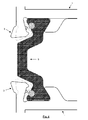
- Figure 3 shows a cross-section of a constructional form of a heat-insulating body 5 designed to form a section according to an embodiment of the present invention.
- the heat-insulating body 5 comprises an elongated central part 51, two approximately trapezoidal heads 52 and two sections 53 which connect the heads 52 to the ends of the central part 51.
- the central part 51 and the two connecting sections 53 form roughly an ⁇ (omega) shape.
- the two approximately trapezoidal heads 52 are configured so as to engage inside the seats 2.
- the body of heat-insulating material has a substantially straight, I-shaped, cross-sectional form.
- the body of heat-insulating material could have any open or closed (tubular) cross-sectional form.
- the body of heat-insulating material 5 may be made of polyamide, PVC, ABS or other plastic which is substantially rigid and cannot be easily compressed.
- an advantageous material in terms of weight and (low) thermal conductivity is Tefanyl.
- the heat-insulating body 5 comprises a portion 54 thereof made of soft material.
- This portion 54 of softer material may be in the form of a cord with a roughly circular cross-sectional form suitable for housing inside a special cavity formed in the body of heat-insulating material 5.
- "softer material” is understood as meaning a material suitable for being compressed more easily than the remainder of the heat-insulating body.
- this material has a density less than that of the remainder of the heat-insulating body 5.
- the cross-section of the cavity which receives the cord 54 is substantially circular with a diameter of between about 1.0 mm and 1.5 mm. In a preferred embodiment, the diameter of the cavity is equal to about 1.2 mm.
- the cord is obtained by means of coextrusion.
- This cord may consist of glue or the like which can be activated when exposed to a certain pressure and/or to a certain temperature.
- the portion 54 of softer material projects slightly from the profile of the body of heat-insulating material 5.
- the amount of this projection may be in the region of 0.1 mm to 0.2 mm and preferably is equal to about 0.15 mm.
- the portion 54 of softer material is substantially flush with the profile of the body of heat-insulating material 5.
- the portion 54 of softer material is inset with respect to the profile of the body of heat-insulating material 5.
- the number and position of the portions 54 of softer material depends on the number of second snugs 4 and their position. In one embodiment (that shown in Figure 3 ) two portions 54 of softer material are provided since each receiving seat 2 is formed by a fixed shoulder and by a deformable tooth 3 and only the latter is provided with a second snug 4. In other embodiments (not shown), for each head 52, two portions 54 of softer material, one on each opposite side of each head, may be provided. In other embodiment (not shown), for each side of each head 52, two (or more) portions 54 of softer material may be provided.
- the portions 54 of softer material may be made with a substantially flexible PVC, a rubber, an adhesive, a mastic or similar material.
- a material which is considered particular suitable for the purpose is resin from the family NORYL® available, for example, from GE plastics, which has its head office in Pittsfield, Massachusetts, United States of America, a division of General Electric.
- the resin NORYL PPX7110 (unreinforced), the resin NORYL PPX7112 (paintable/unreinforced), the resin NORYL PPX7115 (unreinforced), the resin NORYL PPX630 (30% reinforced) or the resin NORYL PPX640 (40% reinforced) may be used.
- these resins have a better transmittance than polyamide or a similar material.
- Figure 4 shows an enlarged cross-section of a portion of a section according to an embodiment of the invention, comprising a heat-insulating body 5 and two half-shells 1.
- assembly of the heat-insulating body 5 on the half-shells 1 is shown: inside each seat 2 the tooth passes from its initial position (where it allows the head 52 of the body 5 of heat-insulating material to be inserted inside the respective seat 2), into its locking position (indicated by broken lines).
- the second snug 4 of each tooth 3 has penetrated into the respective portion 54 of softer material, firmly fixing the body 5 of heat-insulating material to the section. Penetration of the second snug occurs, advantageously, in succession after penetration of the first snug.
- the Applicant has measured the pull-out strength - in accordance with that stipulated by the standard UNI ENI 14024 category W - of the half-shells 1 when assembled with the body of heat-insulating material according to the embodiment of Figure 4 . According to this standard, the minimum pull-out value must be 24 Newton per mm. The Applicant has measured a pull-out strength value of about 400 to 500 kg on a 10 cm sample, i.e. far greater than that stipulated by the above-mentioned standard.
- the body of heat-insulating material is formed by co-extruding a first material which has a first density with a second material which has a second density less than the first density.
- machining of the half-shells with knurling of the bottom of the seat is avoided.
- the section, together with the second snug (or with more than one second snug), is obtained by means of drawing and the assembly process may be performed continuously on a production line. This results in a considerable reduction in costs and machining time.
- the two half-shells may be obtained by means of extrusion separately and independently of one another or may be obtained by means of a single die with subsequent cutting of a bridge-piece joining them together.
Landscapes
- Engineering & Computer Science (AREA)
- Civil Engineering (AREA)
- Structural Engineering (AREA)
- Wing Frames And Configurations (AREA)
- Special Wing (AREA)
- Thermal Insulation (AREA)
Abstract
A body of heat-insulating material designed to be assembled with two half-shells made of metallic material, so as to form a section configured to produce a thermal break door or window frame, said body of heat-insulating material comprising a first plastic material having a first degree of compressibility, characterized in that it also comprises a second material with a second degree of compressibility, wherein said second degree of compressibility is greater than said first degree of compressibility.
Description
- The present invention relates to the sector of aluminium or aluminium alloy sections for forming door and window frames or the like. In particular, it relates to a heat-insulating body for forming a section for a thermal break door or window frame.
- In the present description and in the claims the term "half-shell" shall be used to indicate a longitudinally elongated body with a substantially rectilinear axis which has any cross-sectional form and which, when assembled with another corresponding half-shell and a heat-insulating body, forms a section. Each half-shell is typically made of aluminium or aluminium alloy and is typically obtained by means of extrusion. As regards the above, in the present description and in the claims the term "section" shall be used to indicate the assembly consisting of two half-shells and a heat-insulating body. The heat-insulating body is also a longitudinally elongated with any cross-sectional form. Typically, this heat-insulating body is a part obtained by means of extrusion and made of a heat-insulating material.
- For some time "thermal break" sections for forming thermal break door and window frames have been known. In thermal break sections, the aluminium part exposed externally is separated from the inner part by means of heat-insulating bodies. Inside these sections a thermal break chamber with walls consisting of heat-insulating material is formed. Generally, this material is a plastic material. Typically this plastic material is a polyamide. This chamber made partially of plastic material interrupts the transmission of the heat by means of conduction between the outer part and inner part and provides the frame with a high heat-insulating power.
- In the thermal break sections which are known at present the thermal break chamber is formed by inserting the end of two polyamide bars inside special seats provided in two half-shells of the section. Alternatively, heat-insulating bodies with a tubular shape are used. Engagement of the polyamide bars or the tubular body is performed in the flat condition. In other words, the fixing points are positioned on two parallel surfaces. Each of the above-mentioned special seats is delimited by a pair of deformable longitudinal teeth or a deformable longitudinal tooth and a fixed shoulder. During insertion of the bars or the tubular body, the teeth are all open so as to allow, precisely, easy insertion of the bars or the tubular body, respectively. After inserting the bars or the tubular body inside the respective seats rolling is performed. The rolling machine compresses the teeth of either seat and ensures rigid joining together of the bars, or the tubular body, made of heat-insulating material and the half-shells.
- Typically, before inserting the polyamide bars into the seats, at least a part of the bottom of the seats is knurled. Knurling of the bottom is performed in order to improve the so-called "pull-out strength", i.e. fix more firmly the polyamide bars to the section.
- The Applicant has noted that this knurling of the bottom of the receiving seats constitutes a further machining operation and involves the use of a special apparatus with knurling rollers. Inconveniently, the knurling apparatus must be adapted to the shape and form of the sections.
- An even greater problem, which is associated with knurling of the bottom of the seats and has been identified by the Applicant, consists in the fact that this knurling operation requires time and hinders production-line assembly of the section.
- Moreover, inconveniently, knurling of the bottom of the seats prevents sliding of the bars (or tubular body) inside the said seats. This constitutes a serious problem limiting productivity.
- The Applicant aims to provide a section which can be assembled on a production line ensuring greater productivity, but which, at the same time, has high pull-out strength properties. The fact of being able to assemble a thermal break section on a production line constitutes a significant advantage and results in major advantages from a cost point of view. In fact, being able to dispense with performing a machining operation avoids the associated costs of the machining apparatus (knurling rollers) and reduces the machining times.
- The above objects, together with others, are obtained owing to the fact that at least one second snug is provided on the tooth which locks the heat-insulating body. When the tooth is bent to lock the heat-insulating body, this second snug engages with the heat-insulating body and locks it firmly. According to the invention, the second snug engages with the heat-insulating body along a portion thereof which has a density less than that of the remainder of the heat-insulating body. This portion, which has, precisely, a density less than that of the remainder of the heat-insulating body, is compressed by the second snug and stably locks the heat-insulating body, preventing it from sliding.
- According to a first aspect, the present invention provides a heat-insulating body designed to be assembled with two half-shells made of metallic material, so as to form a section configured to produce a thermal break door or window frame, said body of heat-insulating material comprising a first plastic material having a first degree of compressibility, characterized in that it also comprises a second material with a second degree of compressibility, wherein said second degree of compressibility is greater than said first degree of compressibility.
- "Degree of compressibility" in the present description and in the claims is understood as meaning the capacity of a body, made of a certain material, to be compressed. A low degree of compressibility indicates that the material is substantially rigid and may be penetrated with difficulty. A greater degree of compressibility indicates that the material may be penetrated more easily than a material with a smaller degree of compressibility.
- The first material is preferably chosen from the group composed of: polyamide, PVC, ABS or Tefanyl.
- The first material is preferably chosen from the group composed of: a substantially flexible PVC, a rubber, a glue, a mastic or a resin.
- The second material has preferably a density less than that of the first material.
- In one embodiment, the second material is in the form of a cord with any cross-sectional form which is inset at least partially inside a special cavity formed in the body of heat-insulating material.
- The cord may be obtained by means of coextrusion with the remainder of the body of heat-insulating material.
- In one embodiment, the cord may comprise a glue which can be activated when exposed to a certain mechanical pressure and/or to a certain temperature.
- The cord may have a form, viewed in cross-section, which is approximately circular, with a diameter ranging generally between about 1.0 mm and 1.5 mm.
- The cord may have an open form, viewed in cross-section, for example an Ω, C or I shaped form, or a closed form.
- In one embodiment, the body of heat-insulating material comprises two end heads and the second material with a second degree of compressibility is arranged in the region of said heads.
- A detailed description of the invention is now provided purely by way of a non-limiting example, to be read with reference to the accompanying sets of drawings, in which:
-
Figure 1 is an enlarged cross-sectional view of a portion of a known half-shell for forming a section for a thermal break door or window frame; -
Figure 2 is an enlarged cross-sectional view of a portion of a half-shell which can be used with a heat-insulating body according to an embodiment of the present invention; -
Figure 3 is an enlarged cross-sectional view of a bar of heat-insulating material according to an embodiment of the invention; -
Figure 3a is an enlarged cross-sectional view of a bar of heat-insulating material according to another embodiment of the invention; and -
Figure 4 is an enlarged cross-sectional view of a portion of an assembled section with a heat-insulating body according to an embodiment of the invention. - With reference initially to
Figure 1 , this shows an enlarged cross-sectional view of a portion of a known half-shell 1 for forming a section for a thermal break door or window frame. In particular, it shows an enlarged view of aseat 2 designed to receive the end of a heat-insulating body (not shown inFigure 1 ). Theseat 2 defines a roughly trapezoidal space and is delimited by abottom surface 21 and by twosides first side 22 is a fixed shoulder, while thesecond side 23 is formed by adeformable tooth 3. In other embodiments (not shown), the shoulder is replaced by another deformable tooth and therefore theseat 2 is delimited by twodeformable teeth 3. Typically, agroove 24 is provided in the zone where thebottom 21 of theseat 2 joins thedeformable tooth 3. Thedeformable tooth 3 of theseat 2 which receives the heat-insulating body terminates in asnug 31 which extends towards the inside of theseat 2. - In order to assemble a
section 1 and a heat-insulating body (not shown inFigure 1 ) inserted partially inside its seat, thelocking tooth 3 is rotated so that the projecting snug 31 moves towards thebottom 21 of theseat 2. Obviously, in the case where theseat 2 is delimited by twoteeth 3, both are rotated towards thebottom 21. In this way the heat-insulating body is prevented from coming out of its seat and sliding of the heat-insulating body with respect to thesection 1 is limited. In the known sections, typically, part of thebottom 21 of theseat 2 is knurled so as to further improve the pull-out strength. -
Figure 2 shows a cross-sectional view of a portion of a half-shell 1 designed to mate with a body of heat-insulating material according to a second embodiment of the present invention so as to form a section of a thermal break door or window frame. In particular it shows an enlarged view of aseat 2 designed to receive the end of a heat-insulating body (not shown inFigure 2 ). Theseat 2 defines a roughly trapezoidal space and is delimited by abottom surface 21 and by twosides first side 22 is a fixed shoulder, while thesecond side 23 is formed by adeformable tooth 3. In other embodiments (not shown), the shoulder is replaced by anotherdeformable tooth 3 and therefore theseat 2 is delimited by twodeformable teeth 3. Typically, agroove 24 is provided in the zone where the bottom 21 of theseat 2 joins thedeformable tooth 3. Thedeformable tooth 3 of theseat 2 which receives the heat-insulating body terminates in afirst snug 31 which extends towards the inside of theseat 2. According to the present invention, in addition to the first snug, at least onesecond snug 4 designed to penetrate into the heat-insulating body is provided, as will be explained more fully below. - Preferably, the
second snug 4 is provided in a lower position than thefirst snug 31, in the side of thetooth 3 which delimits theseat 2. In other words, saidsecond snug 4 is provided between thegroove 24 and thefirst snug 31. - Obviously, the
second snug 4 may have any cross-sectional form, i.e. for example that of an isosceles triangle with a rounded vertex. It could, however, have a form with a sharp corner and a square, pentagonal, hexagonal or similar cross-section. -
Figure 3 shows a cross-section of a constructional form of a heat-insulatingbody 5 designed to form a section according to an embodiment of the present invention. Viewed in cross-section, the heat-insulatingbody 5 comprises an elongatedcentral part 51, two approximatelytrapezoidal heads 52 and twosections 53 which connect theheads 52 to the ends of thecentral part 51. Thecentral part 51 and the two connectingsections 53 form roughly an Ω (omega) shape. The two approximatelytrapezoidal heads 52 are configured so as to engage inside theseats 2. In an alternative, shown inFigure 3a , the body of heat-insulating material has a substantially straight, I-shaped, cross-sectional form. In any case, for the purposes of the present invention, the body of heat-insulating material could have any open or closed (tubular) cross-sectional form. - The body of heat-insulating
material 5 may be made of polyamide, PVC, ABS or other plastic which is substantially rigid and cannot be easily compressed. The Applicant has established that an advantageous material in terms of weight and (low) thermal conductivity is Tefanyl. According to a preferred embodiment of the present invention, the heat-insulatingbody 5 comprises aportion 54 thereof made of soft material. Thisportion 54 of softer material may be in the form of a cord with a roughly circular cross-sectional form suitable for housing inside a special cavity formed in the body of heat-insulatingmaterial 5. Generally, for the purposes of the present invention, "softer material" is understood as meaning a material suitable for being compressed more easily than the remainder of the heat-insulating body. Typically, this material has a density less than that of the remainder of the heat-insulatingbody 5. In one embodiment, the cross-section of the cavity which receives thecord 54 is substantially circular with a diameter of between about 1.0 mm and 1.5 mm. In a preferred embodiment, the diameter of the cavity is equal to about 1.2 mm. Preferably, the cord is obtained by means of coextrusion. - This cord may consist of glue or the like which can be activated when exposed to a certain pressure and/or to a certain temperature.
- According to a first embodiment, the
portion 54 of softer material projects slightly from the profile of the body of heat-insulatingmaterial 5. The amount of this projection may be in the region of 0.1 mm to 0.2 mm and preferably is equal to about 0.15 mm. In a possible variant, theportion 54 of softer material is substantially flush with the profile of the body of heat-insulatingmaterial 5. In a further embodiment, theportion 54 of softer material is inset with respect to the profile of the body of heat-insulatingmaterial 5. - The number and position of the
portions 54 of softer material depends on the number ofsecond snugs 4 and their position. In one embodiment (that shown inFigure 3 ) twoportions 54 of softer material are provided since each receivingseat 2 is formed by a fixed shoulder and by adeformable tooth 3 and only the latter is provided with asecond snug 4. In other embodiments (not shown), for eachhead 52, twoportions 54 of softer material, one on each opposite side of each head, may be provided. In other embodiment (not shown), for each side of eachhead 52, two (or more)portions 54 of softer material may be provided. - The
portions 54 of softer material may be made with a substantially flexible PVC, a rubber, an adhesive, a mastic or similar material. A material which is considered particular suitable for the purpose is resin from the family NORYL® available, for example, from GE plastics, which has its head office in Pittsfield, Massachusetts, United States of America, a division of General Electric. For example, the resin NORYL PPX7110 (unreinforced), the resin NORYL PPX7112 (paintable/unreinforced), the resin NORYL PPX7115 (unreinforced), the resin NORYL PPX630 (30% reinforced) or the resin NORYL PPX640 (40% reinforced) may be used. Advantageously these resins have a better transmittance than polyamide or a similar material. -
Figure 4 shows an enlarged cross-section of a portion of a section according to an embodiment of the invention, comprising a heat-insulatingbody 5 and two half-shells 1. In particular assembly of the heat-insulatingbody 5 on the half-shells 1 is shown: inside eachseat 2 the tooth passes from its initial position (where it allows thehead 52 of thebody 5 of heat-insulating material to be inserted inside the respective seat 2), into its locking position (indicated by broken lines). As can be noted, in the locking position, thesecond snug 4 of eachtooth 3 has penetrated into therespective portion 54 of softer material, firmly fixing thebody 5 of heat-insulating material to the section. Penetration of the second snug occurs, advantageously, in succession after penetration of the first snug. - The Applicant has measured the pull-out strength - in accordance with that stipulated by the standard UNI ENI 14024 category W - of the half-
shells 1 when assembled with the body of heat-insulating material according to the embodiment ofFigure 4 . According to this standard, the minimum pull-out value must be 24 Newton per mm. The Applicant has measured a pull-out strength value of about 400 to 500 kg on a 10 cm sample, i.e. far greater than that stipulated by the above-mentioned standard. - In an alternative embodiment, the body of heat-insulating material is formed by co-extruding a first material which has a first density with a second material which has a second density less than the first density.
- Advantageously, according to the invention, machining of the half-shells with knurling of the bottom of the seat is avoided. The section, together with the second snug (or with more than one second snug), is obtained by means of drawing and the assembly process may be performed continuously on a production line. This results in a considerable reduction in costs and machining time.
- As a result of the present invention it is possible to perform on a production line assembly with a productivity substantially twice that of the productivity for assembly of the half-shells where the bottom of the seats is knurled.
- The two half-shells may be obtained by means of extrusion separately and independently of one another or may be obtained by means of a single die with subsequent cutting of a bridge-piece joining them together.
Claims (10)
- Body of heat-insulating material (5) designed to be assembled with two half-shells made of metallic material, so as to form a section configured to produce a thermal break door or window frame, said body of heat-insulating material comprising a first plastic material having a first degree of compressibility, characterized in that it also comprises a second material (54) with a second degree of compressibility, wherein said second degree of compressibility is greater than said first degree of compressibility.
- Body of heat-insulating material (5) according to Claim 1, characterized in that said first material is preferably chosen from the group composed of: polyamide, PVC, ABS or Tefanyl.
- Body of heat-insulating material (5) according to Claim 1, characterized in that said first material is chosen from the group composed of: a substantially flexible PVC, a rubber, an adhesive, a mastic or a resin.
- Body of heat-insulating material (5) according to Claim 1, 2 or 3, characterized in that said second material (54) has a density less than that of the first material.
- Body of heat-insulating material (5) according to any one of the preceding claims, characterized in that said second material (54) is in the form of a cord with any cross-sectional form inset at least partially inside a special cavity formed in the body of heat-insulating material (5).
- Body of heat-insulating material (5) according to Claim 5, characterized in that the cord is obtained by means of coextrusion with the remainder of the body of heat-insulating material (5).
- Body of heat-insulating material according to Claim 5 or 6, characterized in that said cord comprises a glue which can be activated when exposed to a certain mechanical pressure and/or to a certain temperature.
- Body of heat-insulating material (5) according to Claims 5, 6 or 7, characterized in that said cord has a form, viewed in cross-section, which is approximately circular, with a diameter preferably between about 1.0 mm and 1.5 mm.
- Body of heat-insulating material (5) according to any one of the preceding claims, characterized in that it has an open form, viewed in cross-section, for example an Ω, C or I shaped form, or a closed form.
- Body of heat-insulating material (5) according to any one of the preceding claims, characterized in that it comprises two end heads and in that said second material (54) with a second degree of compressibility is arranged in the region of said heads.
Applications Claiming Priority (1)
| Application Number | Priority Date | Filing Date | Title |
|---|---|---|---|
| IT001933A ITMI20071933A1 (en) | 2007-10-05 | 2007-10-05 | THERMO-INSULATING BODY FOR CREATING PROFILES FOR THERMAL-CUTTING FRAMES |
Publications (1)
| Publication Number | Publication Date |
|---|---|
| EP2045429A2 true EP2045429A2 (en) | 2009-04-08 |
Family
ID=40266120
Family Applications (1)
| Application Number | Title | Priority Date | Filing Date |
|---|---|---|---|
| EP08165573A Withdrawn EP2045429A2 (en) | 2007-10-05 | 2008-10-01 | Heat-insulating body for forming sections for thermal break door and window frames |
Country Status (6)
| Country | Link |
|---|---|
| US (1) | US20090226660A1 (en) |
| EP (1) | EP2045429A2 (en) |
| CN (1) | CN101403274A (en) |
| BR (1) | BRPI0804237A2 (en) |
| IT (1) | ITMI20071933A1 (en) |
| MA (1) | MA30375B1 (en) |
Cited By (2)
| Publication number | Priority date | Publication date | Assignee | Title |
|---|---|---|---|---|
| GB2591294A (en) * | 2020-01-27 | 2021-07-28 | Garner Aluminium Extrusions Ltd | A method |
| GB2603213A (en) * | 2021-01-28 | 2022-08-03 | Garner Aluminium Extrusions Ltd | A window frame assembly |
Families Citing this family (3)
| Publication number | Priority date | Publication date | Assignee | Title |
|---|---|---|---|---|
| ITMI20071932A1 (en) * | 2007-10-05 | 2009-04-06 | Norsk Hydro As | HALF-SHAPED TO MAKE THERMAL OR SIMILAR CUTTING WINDOWS, RELATED PROFILE AND RELATIVE ASSEMBLY PROCESS |
| US9670671B2 (en) | 2015-02-13 | 2017-06-06 | The Bilco Company | Hatch with thermally broken frame |
| US11248412B2 (en) * | 2019-11-18 | 2022-02-15 | Rehme Custom Doors & Lighting, Inc. | Metallic fenestration systems with improved thermal performance and methods of manufacturing same |
Family Cites Families (1)
| Publication number | Priority date | Publication date | Assignee | Title |
|---|---|---|---|---|
| DE4427682C2 (en) * | 1994-08-04 | 1996-12-12 | Ensinger Gmbh & Co | Composite profile for frames of windows, doors, facade elements and. the like |
-
2007
- 2007-10-05 IT IT001933A patent/ITMI20071933A1/en unknown
-
2008
- 2008-09-27 CN CNA2008101769542A patent/CN101403274A/en active Pending
- 2008-10-01 EP EP08165573A patent/EP2045429A2/en not_active Withdrawn
- 2008-10-03 US US12/244,881 patent/US20090226660A1/en not_active Abandoned
- 2008-10-03 BR BRPI0804237-3A patent/BRPI0804237A2/en not_active IP Right Cessation
- 2008-10-06 MA MA31269A patent/MA30375B1/en unknown
Cited By (2)
| Publication number | Priority date | Publication date | Assignee | Title |
|---|---|---|---|---|
| GB2591294A (en) * | 2020-01-27 | 2021-07-28 | Garner Aluminium Extrusions Ltd | A method |
| GB2603213A (en) * | 2021-01-28 | 2022-08-03 | Garner Aluminium Extrusions Ltd | A window frame assembly |
Also Published As
| Publication number | Publication date |
|---|---|
| US20090226660A1 (en) | 2009-09-10 |
| ITMI20071933A1 (en) | 2009-04-06 |
| MA30375B1 (en) | 2009-05-04 |
| CN101403274A (en) | 2009-04-08 |
| BRPI0804237A2 (en) | 2010-01-19 |
Similar Documents
| Publication | Publication Date | Title |
|---|---|---|
| EP2045430A2 (en) | Half-shell for forming thermal break door and window frames or the like, associated section and associated assembly process | |
| EP2045429A2 (en) | Heat-insulating body for forming sections for thermal break door and window frames | |
| KR101507484B1 (en) | Windows and doors with high insulation for easy separation and manufacturing method thereof | |
| WO2008046610A3 (en) | Extruded hollow chamber profile for windows or doors | |
| KR20110056890A (en) | Finishing member of insulation panel and insulation panel with the same | |
| US11859438B2 (en) | Bead for a frame member | |
| WO2007118543A1 (en) | Frame with frame profile and reinforcing components made from thermoplastic materials | |
| KR20190121414A (en) | Profiled belt and method for manufacturing same | |
| US8789323B2 (en) | Method for attachment of an object to a thin-walled profile, such as a fibre glass reinforced profile made by pultrusion, and such a profile | |
| CN102620601A (en) | Crossbow stock with improved track assembly and method | |
| KR101646378B1 (en) | A refrigerator door frame and a method for manufacturing the same | |
| EP2770882B1 (en) | Refrigerating and/or freezing appliance | |
| US7334434B2 (en) | Sliding-type fastener for accessary chain | |
| EP2180460B1 (en) | Attachment member and method of manufacturing the same | |
| EA018490B1 (en) | Method for introduction of expanding sleeve into a soft material | |
| US20160356077A1 (en) | Window frame and/or opening frame | |
| WO2006042592A3 (en) | Assembly screw for fixing fittings, especially strip parts, to hollow-chamber profiled elements | |
| GB2603213A (en) | A window frame assembly | |
| DE202009014203U1 (en) | Shower partition and retaining profile | |
| US10174776B2 (en) | Modular rail system | |
| EP4047168B1 (en) | Method for composing such profile and device applied thereby | |
| CN216841271U (en) | Flexible door and window section bar | |
| JP5770600B2 (en) | Grazing channel and glazing and sash with glazing channel | |
| EP4036361A1 (en) | A window frame assembly | |
| AU2008100201A4 (en) | Retaining sleeve |
Legal Events
| Date | Code | Title | Description |
|---|---|---|---|
| PUAI | Public reference made under article 153(3) epc to a published international application that has entered the european phase |
Free format text: ORIGINAL CODE: 0009012 |
|
| AK | Designated contracting states |
Kind code of ref document: A2 Designated state(s): AT BE BG CH CY CZ DE DK EE ES FI FR GB GR HR HU IE IS IT LI LT LU LV MC MT NL NO PL PT RO SE SI SK TR |
|
| AX | Request for extension of the european patent |
Extension state: AL BA MK RS |
|
| STAA | Information on the status of an ep patent application or granted ep patent |
Free format text: STATUS: THE APPLICATION IS DEEMED TO BE WITHDRAWN |
|
| 18D | Application deemed to be withdrawn |
Effective date: 20130503 |