EP2045401A1 - Procédé pour produire de l'eau au moyen d'une plaque de métal, appareil de production d'eau utilisant une plaque de métal, plaque de métal de collecte d'eau et élément métallique de collecte d'eau - Google Patents
Procédé pour produire de l'eau au moyen d'une plaque de métal, appareil de production d'eau utilisant une plaque de métal, plaque de métal de collecte d'eau et élément métallique de collecte d'eau Download PDFInfo
- Publication number
- EP2045401A1 EP2045401A1 EP07791711A EP07791711A EP2045401A1 EP 2045401 A1 EP2045401 A1 EP 2045401A1 EP 07791711 A EP07791711 A EP 07791711A EP 07791711 A EP07791711 A EP 07791711A EP 2045401 A1 EP2045401 A1 EP 2045401A1
- Authority
- EP
- European Patent Office
- Prior art keywords
- water
- metal plate
- metal
- water collection
- heat
- Prior art date
- Legal status (The legal status is an assumption and is not a legal conclusion. Google has not performed a legal analysis and makes no representation as to the accuracy of the status listed.)
- Withdrawn
Links
Images


Classifications
-
- B—PERFORMING OPERATIONS; TRANSPORTING
- B01—PHYSICAL OR CHEMICAL PROCESSES OR APPARATUS IN GENERAL
- B01D—SEPARATION
- B01D53/00—Separation of gases or vapours; Recovering vapours of volatile solvents from gases; Chemical or biological purification of waste gases, e.g. engine exhaust gases, smoke, fumes, flue gases, aerosols
- B01D53/26—Drying gases or vapours
- B01D53/265—Drying gases or vapours by refrigeration (condensation)
-
- E—FIXED CONSTRUCTIONS
- E03—WATER SUPPLY; SEWERAGE
- E03B—INSTALLATIONS OR METHODS FOR OBTAINING, COLLECTING, OR DISTRIBUTING WATER
- E03B3/00—Methods or installations for obtaining or collecting drinking water or tap water
- E03B3/28—Methods or installations for obtaining or collecting drinking water or tap water from humid air
-
- Y—GENERAL TAGGING OF NEW TECHNOLOGICAL DEVELOPMENTS; GENERAL TAGGING OF CROSS-SECTIONAL TECHNOLOGIES SPANNING OVER SEVERAL SECTIONS OF THE IPC; TECHNICAL SUBJECTS COVERED BY FORMER USPC CROSS-REFERENCE ART COLLECTIONS [XRACs] AND DIGESTS
- Y02—TECHNOLOGIES OR APPLICATIONS FOR MITIGATION OR ADAPTATION AGAINST CLIMATE CHANGE
- Y02A—TECHNOLOGIES FOR ADAPTATION TO CLIMATE CHANGE
- Y02A20/00—Water conservation; Efficient water supply; Efficient water use
-
- Y—GENERAL TAGGING OF NEW TECHNOLOGICAL DEVELOPMENTS; GENERAL TAGGING OF CROSS-SECTIONAL TECHNOLOGIES SPANNING OVER SEVERAL SECTIONS OF THE IPC; TECHNICAL SUBJECTS COVERED BY FORMER USPC CROSS-REFERENCE ART COLLECTIONS [XRACs] AND DIGESTS
- Y10—TECHNICAL SUBJECTS COVERED BY FORMER USPC
- Y10T—TECHNICAL SUBJECTS COVERED BY FORMER US CLASSIFICATION
- Y10T428/00—Stock material or miscellaneous articles
- Y10T428/24—Structurally defined web or sheet [e.g., overall dimension, etc.]
- Y10T428/24355—Continuous and nonuniform or irregular surface on layer or component [e.g., roofing, etc.]
Definitions
- the present invention relates to a method of producing metal plate type water and a metal plate type water production apparatus, in particular a method for producing metal plat type water and a metal plate type water production apparatus comprising a metal plate having a cooler for extracting water from moisture in atmosphere and a water film peeling-off mechanism for peeling off forcibly a water film generated in a surface of the metal plate.
- the present invention relates a water collection metal plate and a water collection metal element, in particular to a water collection metal plate which reforms to a surface to be wetted easily in a water collection property and a manufacture method thereof, using the water collection metal plate a method for constituting a water collection element which becomes as a water collection element for collecting easily water from moisture in atmosphere, and various kinds use method relating to the water collection metal plate and the water collection metal plate element.
- the present invention relates to a method for producing metal plate type water in which water is extracted from moisture in atmosphere being a material of the water and a metal plate type water production apparatus.
- the metal plate type water production method and the metal plate water production apparatus of the present invention can provide a manufacture group adapted suitably to the various places where water is necessary and the services.
- a metal plate dislikes water in generally.
- the technique for aiming the metal plate type water production method and the metal plate water production apparatus of the present invention resides a large mount water collection from moisture in atmosphere by reforming the surface of the metal plate and therefore this is a reverse idea so far.
- the problem to be solved by the present invention relates to a technique of a metal plate type water production method and a metal plate water production apparatus for extracting a necessity amount water from a free source, the atmosphere being a material and moisture thereof is free.
- a principle of water production technique is a universal natural phenomenon where water dew on a surface of the material by cooling the material. By utilizing this natural phenomenon, it is a problem for requiring a means for maximizing the water production amount to be of the greatest efficiency.
- the main techniques for increasing the water production amount are following two points.
- One point is that generation time of water film for condensing to a surface of a cooled metal plate is early and much water amount Is obtained. For these, it can be solved the problem according to a surface roughing a surface of a metal plate by reforming a hydrophilic property and/or performing a covering film of a hydrophilic property.
- a metal plate water production method is, by cooling a metal plate, a water film is generated on the surface of the metal plate through the dew condensation, at a linear increase amount process before a pre-stage time point the generation water film is flipped off, and the generation water film is peeled off forcibly from the metal plate and collected.
- a metal plate type water production apparatus comprises a metal plate, a cooling means for cooing the metal plate, and a water film peeling-off mechanism for peeling off forcibly by flipping off a water film which generates on a surface of the metal plate.
- a main constitution elementary technique for the metal plate type water production method for extracting water from moisture in atmosphere and the metal plate type water production apparatus will be recited as followings.
- the metal plate type water production method and the metal plate type water production apparatus of the present invention by cooling the metal plate reformed the surface by performing the hydrophilic property covering film by the cooling means, by producing effectively the moisture in atmosphere the water film is generated and at the time of the linear increase amount process of the water film generated on the surface of the metal plate and the immediately before the water increase obstruction phenomenon (the saturation state) by the thickness of the generation water film, the generation water is peeled off forcibly from the metal plate where the generation water film is wiped off by the wiper or flipped off by the ultra sonic vibrator and so on, thereby it is possible to produce the much large water etc..
- the increase amount effect only by the wiper becomes about 1,000 times per month under the environment of the low humidity degree (30% degree) in comparison with the non-processed metal plate using no wiper.
- the general water taking-in means requires large funds for preparing the water source, the power source and the water sending infarction, it is hardly to practice by an individual person level.
- the metal plate type water production method and the metal plate type water production apparatus of the present invention it is possible to take-in the necessary water amount at the place where no infraction exists such as the desert, the separated island, and the mount area. It may safely be said the oasis of the desert where the water is possible to transported by the truck.
- the main use of the water collection metal plate and the water collection metal element being the easy wet water collection system of the present invention are "metal plate type water production apparatus” for collecting the large amount water from the atmosphere, “building cooling apparatus” for cooling a whole of the building, “humidifying and dehumidifying apparatus having the humidity apparatus and the dehumidify apparatus and having both functions” for controlling the humidity of the room air, and “roof snow removal apparatus” for removing automatically the snow on the roof. Since these apparatuses hardly are required the energy such the electric power and the fuel, it may safely to said as the future indicating environment apparatus.
- the present invention relates to provide the industrial material being the main element with these apparatuses.
- the problem to be solved by the present invention is the manufacture method for reforming the water collection metal plate to be the surface having the superior easy wet collection performance and the use manner of the water collection system element of the present invention with the respective apparatuses shown in the above stated items and hereinafter it will be explained in followings.
- the necessary condition is the maximization of the valid surface area per the unit effective area of the metal plate surface. For this, it is necessary to process the roughness performance of the metal plate surface.
- the metal plate having the high water collection performance As a second item, it performs the surface reformation to obtain the metal plate having the high water collection performance. It is necessary to generate the hydrophilic property material crystal at the adhesion condition to the metal crystallization under the enforcement condition for generating the high water collection of the hydrophilic property material such as oxide titanium (Ti02) or oxide silicon (Si02). To adhere the crystals together these two materials, it is necessary to carry out the roughness performance process to the metal crystal face.
- the hydrophilic property material such as oxide titanium (Ti02) or oxide silicon (Si02).
- the problem about the water production apparatus According to the united nation white paper, the world population concerned by the water insufficiency is about nine hundred million at the present time, and it will be estimated to be forty hundred million at about 2075 year. The nature fierceness will rob the life from the peoples. Water is dispensable for the living. In future, since the already known water source decreases, it will require strongly the water taking-in method which does not depend on the already known water source.
- the present invention relates to provide the water production apparatus as a means for requiring the moisture in atmosphere and collecting the much amount water at a low cost and at a cheap price.
- Seawater desalination plant There is the seawater desalination plant for obtaining the large amount water as the already known water taking-in method, however this has following demerits. It will be introduced at the large city near to the sea and having the large funds, however it will not be received the benefit at the depopulated area from the cost against effect aspect. As a result, the peoples who are unable to make the life and leave the village and make the champ around the city and this become the generation source of the various problems.
- the problem about the building cooling apparatus This is an international problem and this relates to the electric power saving being the promise of Kyoto agreement.
- the large electric power consumption is the summer time cooling electric power. It requires a means which does not depend on the cooling using the electric power.
- the present invention is to provide the building cooling apparatus having a high performance and a low cost as a means for cooling a whole building by applying the evaporation heat being the natural phenomenon.
- the problem about the room humidifying apparatus The present building equips the air conditioning apparatus however it have hardy the humidifying function, thereby room air presents the dry condition through year. Accordingly, to attain the comfortable space it is necessary to add the humidity.
- the small space use humidifying apparatus is putted on the market, however no large space use humidifying apparatus exists. Since it increases many peoples who are unbearable in the dry space at the long time, it requires the large space use humidifying apparatus.
- the present invention relates to provide the humidifying apparatus having the high performance at the low cost.
- the problem about the room humidifying and dehumidifying apparatus The air in the underground room and the tunnel is damp. To the person who works in this space and in the installation of the apparatuses being weak against the humidity, it requires the humidification and the dehumidification. It is possible to supply the market air conditioning apparatus, however it is hardy satisfy the effect against cost. Accordingly, to satisfy from this aspect it requires the humidifying and dehumidifying apparatus having the low price.
- the present invention relates to provide the humidifying and dehumidifying apparatus having the high performance at the low cost.
- the problem about the room humidifying and dehumidification apparatus To maintain the comfortable room space, it requires the humidifying and dehumidifying apparatus for satisfying the humidification and the dehumidification through year, however there is no market article. It can be solved by the apparatus, which satisfies both of the above stated humidifying apparatus and the above stated dehumidifying apparatus.
- the problem about the roof snow removal apparatus The aim is to remove automatically the roof snow by no electric power use.
- the death and injury accident due to the fall-down during the snow takedown working in the heavy snow area occurs frequently.
- the snow takedown use apparatus is put on the market, however these apparatuses have the defects in the design, the treatment performance, the introduction cost, the running cost, the noise and a result it obstructs the propagation.
- the present invention relates to the room snow removal apparatus in which the above stated defects can be dissolved.
- the essential point of the present invention resides the metal plate having the minute surface in which the effective surface area after the processing is enlarged with the surface area before the processing, and the water film is generated by making the dewdrops of the moisture in atmosphere on the surface of the metal plate, the generation water film is flipped off and the water film is peeled off forcibly and is collected.
- the roughness performance metal plate can be used as the components for improving aspects from the water-cut performance and the sanitary performance for the home appliance products and the miscellaneous goods.
- the high water collection performance surface reformation of the metal plate It is the processing for reforming the metal surface by solid fixing the different material, which has the hydrophilic property material with the metal surface of the metal plate.
- the enforcement management is important.
- the hydrophilic property material is powder body size, and it is made less than about 1/100 with the roughness area of the metal plate, then it can maintain the effective surface area.
- This apparatus concerns to provide the life foundation for the peoples in world who want to water. Since the living life will be disappeared without the water, the water is dispensable to ensure the living. It is possible to collect the water even the place where there is no power source and no water source by the electric power for requesting the sunlight and the wind force, thereby it can be said safely that the water production apparatus is the transportable oasis in the desert.
- the demands are the greening in the desert, the food production service water, the drink water, etc. and it can provide the basis source for consisting the human sociality.
- this apparatus can apply effectively the evaporation phenomenon of water. It will have the effect in which the consumption during the summer period becomes half by the natural phenomenon. In the city where the building is stood closely, it utilizes to a whole building, a whole town becomes cool, and the customer gathering effect become to heighten.
- the home appliance product for the small space use is put the market, however there is the need for the large space use such as the building, the gymnasium etc. but it is not put in the market.
- the present invention will match to this need.
- the room humidity as the comfortable space is about 50% degree, it can provide the apparatus for adjusting automatically the humidity.
- the dehumidifying and humidifying apparatus can provide the product having both dehumidification and humidification functions and the control means for adjusting automatically to have the most suitable space humidity and can provide the article which hardly necessities the electric power corresponding the large space.
- This apparatus is the most easily product as the easy wet-ability water collection metal plate use. It can use the free power source such as the water collection metal plate and the underground heat and can avoid the freezing. It can provide the roof snow removal apparatus having the zero running cost.
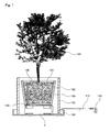
- a mode of a plant automatic water supply apparatus E as one embodiment of a metal plate type water production method and a metal plate type water production apparatus. Further, an example of a case of a metal plate in which a surface of the metal plate is performed with a hydrophilic property covering film, between two aluminum (Al) plates an aluminum (Al) heat plate enclosed a heat medium is adopted, and to carry out a peel-off of a generation water film a wiper for wiping off adhesion water (a generation water film) of a metal plate surface is adopted.
- This embodiment of the plant automatic water supply apparatus has a main body size of about 20 cm, and a small size cylindrical stand of a height 5 cm.
- the main essential constituting elements of the plant automatic water supply apparatus E are a main case 10, a metal plate 30, a gear motor 40, a wiper 50, a cooler 60, a control means 70, a water level sensor 90, and a water introduction tube 100, etc.
- a power supply in this explanation is a commercial electric power and a sunlight power generating means and a wind power generating means are omitted from this explanation.
- a foliage plant 121 is planted on a soil 22 and a pot 123.
- a tube hole 124 for penetrating the water introduction tube 100 has opened in advance.
- the planter 120 is mounted on the plant automatic water supply apparatus E.
- an ornament cage 125 and a receiving dish 126 are set.
- a power supply cord 110 is inserted to a plug receptacle 130 through a lower end of the ornament cage 125.
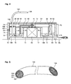
- the main case 10 has a motor room 11 at a central portion and in this motor room the gear motor 40 is stored and is fixed using plural motor screws 12.
- a rotating shaft 41 of the gear motor 40 is projected from toward an upper portion from a penetrating hole 13 and the wiper 50 is installed.
- a specification of the motor gear 40 will be explained. It is desirable to obtain a rotating speed having a low speed about ten seconds per one rotation. The reason is that since the wiper 50 slides to the hydrophilic property covering film of the metal plate 30, it is necessary to attain the wear and tear prevention and the life extension. As a result, to lower the rotational number the motor having the gear is used.
- the plant automatic water supply apparatus E extracts water from the moisture in atmosphere, the inhalation and the exhaust are important.
- plural stands 16 are provided on the plant automatic water supply apparatus E and are floated from a floor surface and an opening 17 is provided.
- the air entered from the opening 17 reaches to an inflow port 18 and flows into a water reservation room 14.
- the air entered in the water reservation room 14 is dehumidified by the metal plate 30 and becomes light and moves towards an upper portion and flows out from the outflow port 19. Since the entering and outflow air amount affects to the water production ability, it is important to provide the large areas of the opening 17, the inflow port 18 and the outflow port 19 being the air flow passages as possible.
- the metal plate 30 will be explained with Fig. 3 and Fig. 4 .
- a heat medium having a superior heat conductivity is enclosed between two aluminum (Al) plates and a surface of one aluminum (Al) plate is a hydrophilic property heat plate in which a hydrophilic property covering film is performed.
- the hydrophilic property covering film is an inner side surface 31 of the metal plate 30 constituted with a ring shape.
- the heat plate has the superior heat conductivity, it has a characteristic even one point of the heat plate is cooled a whole of the heat plate is cooled.
- the installation position of the metal plate 30 is a central portion of the water reservation room 14 of the main case 10, a horizontal direction thereof is fixed by ribs 15 and an upper portion and a lower portion thereof is fixed by plural pressing metal fittings 20.
- the pressing metal fittings 20 are fixed to a side face of the main case 10 by plural pressing metal fitting fix screws 21.
- the wiper 50 will be explained with Fig. 3 and Fig. 4 .
- the wiper 50 is constituted with a wiper arm 51 and a wiper blade 52 enable to attach to a tip end thereof and installed to the rotating shaft 41.
- the wiper blade 52 as shown in Fig. 4 , is installed to the inner side surface 31 of the metal plate 30 with a bend state.
- the material of the wiper blade 51 is a soft resin sheet having about thickness of 0.15 mm.
- the cooler 60 will be explained with Fig. 3 and Fig. 4 . Since the plant automatic water supply apparatus E is mainly the planter plant, it is unnecessary to use the large amount water. As a result, a Peliter unit is adopted as the cooler having 20 deg. The cool air of the cooler 60 is transmitted surely to the metal plate 30 through a cool air transmission portion 61. The cool air transmission portion 61 is fixed using a soldering etc.
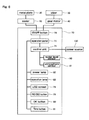
- the control means 70 will be explained with Fig. 2 , Fig. 3 , Fig. 4 and Fig. 6 .
- the control means 70 is a brain of the plant automatic water supply apparatus E and is an electric system control portion, an information type processing portion and a user operation portion.
- the related component group is a control unit 71, the gear motor 40, the cooler 60, the water level sensor 90, an atmosphere sensor 91, and a power source cord 110, etc.
- the main content of the control and information processing is that to obtain proper information from the water level sensor 90 and the atmosphere sensor 91, it is the operation/stop command at the necessary time to the gear motor 40 and is the operation/stop command to the cooler 60 at the most suitable time and is the operation/stop command to the related respective components and a discrimination of the existence of the power supply input power from the power supply cord 110.
- the control unit 71 for constituting an electron circuit of the control means 70 comprises of the atmosphere sensor 91 for measuring the humidity and the temperature and a function for estimating a theoretic water production amount from the measured data. Under the measuring method installed in advance, comparing with the given atmosphere data in all time, it has a function for operation continuing by judging itself a most suitable operation relating the water production.
- An operation panel 72 is provided on an outer surface of the control means 70. It will be explained with Fig. 6 .
- the operation panel 72 is constituted by a liquid crystal screen 73, an ON/OFF button 78, an increase/decrease button 79 for setting an increase and a decrease of the water amount, a number setting button 81 for setting a water supply number, an electrification light (red color) 82 for confirming an ON/OFF state, an operation light (blue color) 83 for confirming the water production operation state, and a confirmation button 80 for confirming the setting contents, etc.
- the electrification light 82 is a display for viewing ON/OFF state.
- the red color lighting shows the electrification time, a putting-out lighting is no electrification.
- the operation lighting 83 is a display light for viewing the water production state.
- the blue color lighting shows the water production operation time, a putting-out lighting shows the water stopping time. Further, it operates during the lighting state (the electrification time) of the electrification light 82 and lights on.
- the water level sensor 90 will be explained with Fig. 3 and Fig. 4 .
- An installation place of the sensor is a lower portion of the cooler 60 and positions in the water reservation room 14 and fixes to an inner wall of the main case 10.
- the role of the sensor monitors the water amount and the water level made by the plant automatic water supply apparatus E and transmits the information to the control unit 71 to have a predetermined amount at all times.
- the control unit 71 commands the operation/stop of the gear motor 40 and the cooler 60 under this information and burdens the important role.
- the water introduction tube 100 will be explained with Fig. 1 , Fig. 2 , Fig. 3 , Fig. 4 and Fig. 5 .
- the use method and aim are to send to the roots of a foliage plant 121 from the plant automatic water supply apparatus E as shown in Fig. 1 .
- a principle of the water production is a combined technique of the hydrophilic property fibers and a capillary phenomenon.
- an outer covering is, as shown in Fig. 5 , a soft resin tube 101 such as silicon.
- a water induction outer covering 104 combined a hydrophilic property string 102 bounded in a linear shape such as a hydrophilic property fiber with a water-repellent property outer covering 103 is inserted.
- Both ends of the water introduction tube 100 are slant cross-section 105, as shown in a right side of Fig. 5 , this cross-section shape is easily the inflow and the discharge of water.
- An inflow side of the water reservation room 14 dipped in the water 106 and a discharge side is contacted and fixed the slant cross-section 105 toward a down direction against the roots of the foliage plant 121.
- the inflow water is transmitted forcibly in the water introduction string 104 and reaches to an end of the discharge side and is discharged and dropped to the roots of the foliage plant 121.
- the water is supplemented and the power supply is repeated.
- a water sending is stopped.
- the atmosphere conditions are the temperature of 20°C and the humidity of 60%, hereafter the plant automatic water supply apparatus E will be explained.
- the beforehand working for the use has explained already, such description is omitted.
- the preparation working will be explained.
- the foliage plant 120 is mounted on the plant automatic water supply apparatus E and the power supply cord 110 is inserted to the plug receptacle 130 and then the preparation is completed.
- the commercial AC 1000 volts power supply is used, it adopts the cord having the plug receptacle, however when the sunlight/the wind power generating means and other power supplies are connected, and suited cords will be used.
- the necessary water amount differs from the size and the kind of the plant and the season.
- the standard water amount is made to have 1,000 cc/day, however it is possible to increase or decrease the water supply amount according to the demands.
- the adjustment method of the water supply amount will be explained hereinafter.
- Example: 500cc increase case The increase amount side of the increase/decrease button 87 is pressed with five times, it confirms numeral [500] is displayed in the increase amount display column 74 and when the confirmation button 80 is pressed and then the numeral of the water supply amount display column 75 becomes from [1000] to [1500] and the numeral of the increase amount display column 74 is eliminated.
- the water supply of 1,500cc/day continues.
- Example: 400cc decrease case The decrease amount side of the increase/decrease button 87 is pressed with four times, it confirms numeral [400] is displayed in the decrease amount display column 76 and when the confirmation button 80 is pressed and then the numeral of the water supply amount display column 75 becomes from [1000] to [600] and the numeral of the decrease amount display column 76 is eliminated.
- the water supply of 600 cc/day continues.
- the water supply per one day is carried out dividedly. It is possible to carry out the water amount per one day to carry out the water supply by dividing four times from one time. In the case of one time per one day it carries out at the noon, in the case of two times it carries out 9 a.m. and 3 p.m., in the case of three times, it carries out 9 a.m., 1 p.m. and 5 p.m., and the four times, it carries out 7 a.m., 10 a.m., 1 p.m. and 4 p.m..
- the indication method of the water supply number will be explained with Fig. 6 . It can indicate by pressing the number setting button 81 of the operation panel 72. For example, in the case of the three times supply per day, it displays [3] on the number display column 77 by pressing the number setting button 81 at three times and when the confirmation button 80 is pressed it is the indication completion. In the embodiment, it carries out the number indication until four times. By pressing the number indication button 81, it repeats [1 ⁇ 2 ⁇ 3 ⁇ 4 ⁇ 1]. The division water supply is performed every day to continue as shown in this indication.
- the aim for making the water supply number in plural it is good condition to maintain the healthy condition to the plant, and by obstructing the outflow of the water from the pot 123 it has the effect for preventing the dirt of the installation face.
- the contents of the drive operation will be explained. Firstly, the water production ability of the plant automatic water supply apparatus E will be explained.
- the water production amount is 2,400cc/day, it 100cc/hour is 100cc.
- the drive time of the plant automatic water supply apparatus E is six hours, during the remaining time of eighteen hours it stops automatically the water production drive.
- the division water supply is indicated, it reads out the water supply time and it carries out the water production during the necessary time.
- the electronic circuit in the control unit 71 of the control means 70 comprises the atmosphere sensor 90 for measuring the atmosphere data such as the humidity and the temperature and the estimation function for theoretically calculating the possible water production amount by the information from the atmosphere sensor 91.
- the atmosphere sensor 90 for measuring the atmosphere data such as the humidity and the temperature
- the estimation function for theoretically calculating the possible water production amount by the information from the atmosphere sensor 91.
- the control means 70 is that by arranging this information and it can give the indication for the most suitable drive to the lower rank apparatuses. It continues the drive until to reach to the indicated water amount and it reaches to the predetermined water amount, it becomes the stop waiting condition, and the electrification light 82 lights on and the working light lights off.
- the reason why the wiper 50 is necessitated will be explained.
- the principle of the water production is the natural phenomenon in which since the moisture in atmosphere contacts to the cooled metal plate 30 and it dews on the surface of the metal plate 30. By activating this dew phenomenon and it works to promote the water amount, there is the special covering film (TiO 2 and SiO 2 ) etc.) for reforming the surface in the hydrophilicity.
- the water film On the surface of the metal plate 30 cooled by the cooler 60, the water film generates immediately after the cooling start. This water film increases linearly with the time (the abrupt increase amount process) and when it reaches to the predetermined time the water film increases gently sloping in parabola shape (the gradually increase amount process) and when the generation water film reaches to the predetermined thickness it becomes to the saturation state.
- the normal saturation is about one hour. The time lapses more than this time, it does not be seen the increase amount of the water film.
- the reason of the saturation is that the generation water film itself becomes to the insulating material, since the cooling is obstructed and the temperature difference to the atmosphere runs short, then the dew condensation effect by the cooling vanishes.
- the re-evaporation water amount is included.
- the decency between the lapse time and the generation water amount is that firstly the linear increase amount, next the gradual parabola increase amount, ant the saturated time band is about one hour, the time band to about 30 minutes is the decency of the linear increase amount.
- the water amount difference of the state leaving 60 minutes on the extension line at 30 minutes is about 1.5 times.
- the wiper 50 On the surface of the metal plate cooled by the cooler 60, the water film is generated during the linear shape increase amount process (the abrupt increase process). After 30 minutes the cooling starts, the wiper 50 operates, the surface adhesion water (the generation water film, the adhesion water film) of the metal plate 30 is wiped off, this water falls down to the bottom face of the water reservation room 14, and it is stored as the water 106. This operation is repeated and the water reservation amount increases.
- the operation of the water introduction tube 100 will be explained. In generally, since the height of the plant planter is about 30 cm, it is sufficient by the water supply using the water introduction tube 100.
- the water sending ability of the water introduction tube 100 attains since it is stronger than the suck force of the plant. It is merely the effect of the natural phenomenon, it has the characteristic in which no electric motive forces requires.
- the small size pump in the case where the height of the plant planter is about 1 m or more than.
- the plant automatic water supply apparatus E is stated as the planter plant use small size water production apparatus, however it is possible to apply to the greening use large size water production apparatus for the desert, and the accident • emergency use home water production apparatus and so on. Further, it is possible to apply the humidifying and dehumidifying apparatus of the ground room etc.
- the metal plate 30 can be selected as the most suitable one according to the size and the use of the product to be subjected. It can lineup the product main body for forming small, the super hydrophilic property heat plate ⁇ hydrophilic property heat plate ⁇ heat plate ⁇ aluminum (Al) plate. In this embodiment, it adopts the hydrophilic property heat plate.
- the size of the hydrophilic property heat plate is the outer size of 150 mm, the height of 33 mm and the area of the hydrophilicity face is about 150 cm 2 .
- water collection metal plate A having the easy wet ability and water collection performance
- water collection metal element which is formed as the element used for the various environment means using the heat plate having the superior cool air transportation performance
- water collection metal device C water collection metal device constituted by arranging and piling the plural water collection metal plates B to collect the large amount water from the moisture in atmosphere with the low price.
- the water collection performance is the hydrophilic property from the aspect of the material phenomenon.
- the hydrophilic property the states of the adhesion water on the metal plate will be explained with from Fig. 8 to Fig. 10 .
- Fig. 8 shows the water droplet at the non-hydrophilicity time
- Fig. 9 shows the water block in the hydrophilicity time
- Fig. 10 shows the water film state at the super hydrophilicity time.
- the hydrophilic property progresses, it becomes the water film state and the water collection performance improves.
- the basic element in the present invention is the water collection metal plate A having the easy wet ability performance and the high water collection performance and for collecting water from the moisture in atmosphere.
- the water collection metal plate B is constituted to have the easy use embodiment using the water collection metal plate A as for the various uses and is added the heat plate function having the superior heat transportation performance.
- the water collection metal device C is constituted by arranging and piling the plural water collection metal plates B and collects the large amount water from the atmosphere.
- the material of the water collection metal plate A is stainless (SUS304) and the size is 1,000 mm x 1,000 (1,500) mm x 0.3 mm.
- the size of the water collection device C is the outer shape size of 1 mm x 1 (1.5) mm x 1.8(2.7) m 3 in the case where twenty-four sheet water collection metal plates B are arranged by the space 75mm with the interval.
- the water production apparatus Since the greater part of the need is required the large water amount, it uses the water collection metal device C.
- the target water amount at the humidity of 60%/30% is 2/1 tons per day in the case of the capacity volume of 1.8 m 3 .
- the water unit price per one little is about 0.5 Yen.
- the equipment articles of the water production apparatus are the water collection device C in mainly, the cooling means, the ultra sonic oscillating means, the control means, the water reservoir tank, the stand etc. and then it can realize the water production function.
- the water collection metal plate A attached to the outer wall of the building is used.
- the equipment articles, except for the water collection metal plate A are merely the water pouring use related means for pouring the water to the water collection metal plate A and the water source.
- the water source is the water production apparatus stated in above, the power source uses the generation means of the sunlight power and the wind power and the electric power rates and the water rates becomes zero. There is no standard size to perform by aligning with the building to be subjected.
- the water collection metal plate A is used by leaning it against the outer wall of the building.
- the equipment articles, except for the water collection metal plate A are merely the water pouring use related means for pouring the water to the water collection metal plate A and the water pipe. Further, it is sufficient to have the water production apparatus stated in above installed to the outer portion. There is no standard size to perform by aligning with the wall.
- the water collection metal plate A is used by leaning it against the surrounding portion of the wall in the room.
- the equipment articles, except for the water collection metal plate A, are the cooling means, the ultra sonic oscillating means, the control means, the water discharge system components. There is no standard size to perform by aligning with the wall.
- the humidifying and dehumidifying apparatus uses together the humidifying apparatus with the dehumidifying apparatus as stated in above and it uses the water collection metal plate B. It can supply the both functions by using all of the both apparatuses.
- the size is the same to the dehumidifying and humidifying apparatus stated in above.
- the water collection metal element B is used by mounting it on the roof.
- the equipment articles are merely the heat collection bodies for collecting heat from the free heat source such as the underground heat and the water collection metal element B and the heat introduction wire for connecting thermally between the above stated bodies and the installation use attachment articles.
- the water collection metal plate having the easy wet ability performance and the water collection performance will be explained in hereinafter.
- Fig. 8 is the cross-sectional view showing the water droplet on the surface of the non-hydrophilic property metal plate
- Fig. 9 is the cross-sectional view showing the water block on the surface of the high hydrophilic property metal plate
- Fig. 10 is the cross-sectional view showing the water film on the surface of the super high hydrophilic property metal plate, it shows that it proceeds the hydrophilicity, the water droplet becomes to the water film state.
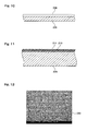
- Fig. 11 is the cross-sectional concept view of the metal plate in which the surface is reformed to high water collection performance
- Fig. 12 is a photography by the electron microscope having twenty hundreds times in the state in which Ti02 crystal structure reveals the super hydrophilic property
- Fig. 13 is the slant state photography
- Fig. 14 is the production process flowchart (the automatic production equipment and the processing summary) of the water collection metal plate A.
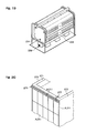
- Fig. 15 is an outer appearance view of the water collection metal plate B
- Fig. 16 is a cross-sectional view of the both sides type water collection metal element B
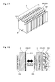
- Fig. 17 is a concept view of the water collection metal device C
- Fig. 18 is an explanatory view of the water collection state and the water film removal state
- Fig. 19 is an outer appearance view of the metal plate type water production apparatus
- Fig. 20 is an installation state view of the building cooling apparatus
- Fig. 21 is a cross-sectional view of the installation state of the building cooling apparatus
- Fig. 22 is an installation state view of the room dehumidifying apparatus
- Fig. 23 is a cross-sectional view of the one side type water collection metal element D
- Fig. 24 is an installation state view of the roof snow removal apparatus
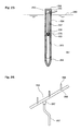
- Fig. 25 is a cross-sectional view of the heat collection body of the roof snow removal apparatus
- Fig. 26 is an enforcement attachment articles of the roof snow removal apparatus.
- a numeral 205 is the metal plate
- a numeral 206 is the water droplet at the non-hydrophilicity time
- a numeral 207 is the water block at the high hydrophilicity time
- a numeral 208 is the water film at the super hydrophilicity time.
- a numeral 210 in Fig. 11 is a schematic view of the state showing an even and uneven state after the roughness performance of the surface of the metal plate 205
- a numeral 211 in Fig. 11 shown the hydrophilicity surface of the thin film to which Ti02 being the hydrophilic property material is attached. Actually, as seen the hydrophilicity surface 211 shown in Fig. 16 , it is the complicate pattern even and uneven surface.
- the material of the metal plate 205 to be used is stainless (SUS304) or the aluminum (Al).
- the roughness performance processing method The sand blast processing in which the parcels having the various different hardness is pressure injected, it makes to have the roughness surface having the many size even and uneven surfaces to form the effective surface area more than about three times with the surface area of the before processing. It is possible to attain this roughness performance processing in plural times using the particle bodies having the different particle grades.
- the crystal face processing method Since in the water collection metal device C used for the water production apparatus the ultra sonic oscillating means is operated to remove the generation water film (the adhesion water film), it is fallen down easily the crystal attached in the after process. Accordingly, it is necessary to carry out the preliminary processing for improving the combination strength to crystallize the material having the different material with the metal on the surface. In this preliminary processing, the even and uneven shape roughness performance is performed to the crystal face of the metal plate using the plasma etc.
- the high water collection performance surface reformation To attain the high water collection performance and to reveal the super hydrophilic property, it is necessary to fix the hydrophilic property material (Ti02) with the thin film state against the roughness surface 210 of the metal plate 205.
- the hydrophilic property material Ti02
- the temperature/time for carrying out the heating and glazing are about 40°C/about 30 minutes.
- the photography shown in Fig. 12 and Fig. 13 show the crystal state of the anatase structure in which Ti02 reveals the super hydrophilic property.
- the hydrophilic property fixing method When immediately after the crystal 230 is generated by the heating, it cools from the high temperature to the normal temperature at a stretch, since it has the decency in which the degree of the hydrophilic property attenuates, it is necessary to cool gradually by controlling the time for lowing from the heating time to the normal time. The time from 400°C to the normal temperature requires about more than thirty minutes.
- the water collection type metal plate A manufacturing method The production process of the water collection metal plate A will be explained with Fig. 14 .
- This carrying-out embodiment is a free-flow line system automatic production equipment. An effective width of this line is about 1,000 mm and is constituted by nine processes.
- This process is one to automatically supply the metal plate 205 having the size of 1,000 mm x 1,000(15,000) mm x 0.3 mm from the stacked place to the line using a robot.
- Process 2 This process is before roughness processing in which a sand blast processing of the pressure injected particle size has about 0.1-1.0 mm, and this process carries out the rough roughness performance against the metal surface.
- Process 3 This process is after roughness processing in which a sand blast processing of the pressure injected particle size has about less than 0.1 mm, and this process carries out the minute roughness performance against the metal surface.
- the roughness performance with the process 1 and the process 2 the roughness surface 210 reveals and thereby the effective surface area is formed more than three times in comparison with the before processing.
- Process 4 This process is one in which the damage is added to the crystal of the metal plate surface by irradiating the plasma or the laser. However, it may be unnecessary to carry out this process, according to the use of the production article.
- Process 5 This process is one against the roughness surface 210 the sol liquid including TiO 2 minute powders is blown out against and coated.
- the film thickness of TiO 2 is a super thin film of 1-0.01 micron and this is an important blowing-out processing condition.
- Ti02 concentration of sol, the injection amount and the injection time etc, are important, the production management is carries out both the control means and the worker.
- This process is one the super hydrophilic property crystal of Ti02 is generated to the anatase structure using a heating use electric furnace.
- the heating temperature and the time management are important and it carries out by an automatic control means.
- the temperature/the time are about 400°C/thirty minutes.
- Process 7 This process is a gradual cooling process for fixing the characteristics of the hydrophilic property. Until the surface temperature of the product article presents about 40-150°C the gradual cooling carries out about twenty-five minutes and until about 150-50°C the abrupt cooling carries out about five minutes. The finish temperature is 50°C and this aim is the safety insurance of the worker.
- This process is a quality control.
- the roughness degree estimation for judging the quality of the roughness is comprised by comparing the reflection light amount according to the light irradiation and a hydrophilic performance estimation means for judging the quality the adhesion state of the water film using a camera image. Further, a good article goes to a next process and a bad article is taken out from the line.
- Process 9 A completed product article is discharged from the line using the robot, and is stacked automatically at the indication position. At the same time, the stamp of the quality sheet is carried out automatically. To the quality sheet, the production date, the inspector No., the serial number etc, are printed. With the above, the production process of the water collection metal plate A finishes.
- a structure of the heat collection body 250 shown in Fig. 25 will be explained.
- a numeral number 250 is a ground face
- 261 is a underground
- 251 is a underground burying body
- 252 is a heat receiving pipe of the underground heat
- 253 is a heat reserving body
- 254 is a heat insulating body
- 258 is a cap
- 251 and 252, 252 and 253, 252 and 254 and 254 and 258 are respectively screw fittings
- 255 is a wire hole provided on the heat reserving body
- 266 is a soldering for thermally jointing a heat introduction body 257 and the heat reserving body 253, and 259 is a rubber ring fitted to a lateral hole of the cap 258.
- a size of the heat collection body 250 is an outer diameter of 90 mm x 1,000 mm.
- the use method of the heat collection body 250 is that as shown in Fig. 25 after the heat collection body 250 has buried in the underground, the heat introduction wire 256 is extended, the underground heat (about 15°C) is transmitted to the one side type eater collection metal element D. In a midway of this transmission, an enforcement use attachment article 256 shown in Fig. 26 is used.
- the underground heat With the heat introduction body 257 extended from the inner portion of the heat collection body 250, the underground heat is heat transported to a heat distribution terminal 268 by passing through a connection port 267 and a heat transfer pipe 266.
- a heat reception from the terminal 268 to the one side type eater collection metal element D is carried out using a thin heat introduction wire (not shown in drawing). Further, a number the one side type eater collection metal element D is the same to a number of the terminal 268.
- a fixing use metal fitting between the roof and the one side type eater collection metal element D are not omitted from the drawing.
- the operation contents to reach the roof snow removal will be explained.
- the underground heat the temperature of the underground in about 1 m from the ground face is about 15°C, it is a limitless heat source in which the change does not generate for year.
- the snow removal apparatus operated, the consumption electric power does not require entirely.
- the one side type eater collection metal element D is heated by the underground heat, it does not freeze during the severe cool time.
- the water film is formed at always on the surface of the hydrophilicity face 211, it presents the wet state, snow drops by the snowslide phenomenon. This operation is repeated and the carrying out of the snow fall-downing working becomes unnecessary.
- the heat conduction system burying body 251, the heat receiving pipe 252, the heat reserving pipe 253, and the heat introduction wire 257 employ the high heat conduction performance cupper system alloy. Further, the heat introduction wire 257 is composed of the bundled twist wire of the copper system alloy thin wires, and at an outer periphery a wire performed by the heat insulating performance covering.
- the heat insulating pipe 254 and the cap 258 are used the complex resin material.
- the heat collection body 250 is a underground burying monopoly one, when the heat source having 10°C exists during the winter time in the vicinity of the building to be subjected to the installation, without this heat connection body 250, only the heat introduction wire 257 will be dispensed. In this case, by removing the covering of the heat introduction wire 257 and a bare body is formed and this part can be thrown into the heat source.
- a modified embodiment of the water collection metal plate A of the present invention will be explained.
- it is unnecessary to operate all of the nine processes. It can select the operation/non-operation of the respective processes according to the use or the customer request. For example, when the goods ordered may be until the process 3, it can product by the automatic production line having the control means in which it can passes through after the process 4.
- the water generated by this metal plate type water production apparatus is the purity water system true water.
- the metal ion (Ca, Mg, Fe, Mn etc.) contained in the service water becomes the primary factor of the slightly burred color and is the obstruction in the process, normally it uses the metal ion blockade agent. To exclude the wastefulness, it is necessary to use the service water in which the metal ion is not contained. Since the generation water of the metal plate type water production apparatus is not contain the metal ion, it is suitable for the dyeing work service water.
- the plant automatic water supply apparatus E shown in from Fig. 1 to Fig. 7 shows the small size production example in which the metal plate type water production apparatus of the present invention is adopted to be the home gardening use and it will be explained the examples for the commercial use, the industrial use, and the home use etc.
- the metal plate type water production apparatus of the present invention will be explained with the metal plate type water production apparatus shown in Fig. 19 . It adopts the metal plate (the water collection device C) having ultra sonic oscillating mechanism shown in Fig. 17 and Fig. 18 .
- the metal plate type water production apparatus of this embodiment is the water production apparatus for extracting from the moisture in atmosphere, in the process of the linear shape increase amount (this indicates the process in which the adhesion water increases linearly the amount from the initial stage of the water film formation) of the generation water film (the adhesion water film) 241 generated by the dew which formed in the surface of the cooled water collection plate (the water collection metal device C), and before stage time of the saturation where the increase amount of the generation water film 214 (the time immediately before the gradual parabola increase), in other words, in the linearly increase amount finish stage (the linearly increase amount finish process) of the generation water film 214, using the ultra sonic vibrator 231 of the ultra sonic oscillating mechanism, the generation water film 214 is flipped off and is peeled off forcibly from the metal plate surface and is collected.
- the ultra sonic vibrator 231 is operated, the ultra sonic vibration is given to the generation water film 214, and the generation water film is flipped off and peeled off forcibly from the surface of the water collection metal plate (the water collection device C) according to the minute vibration.
- the generation water film 214 is flipped off from the hydrophilicity face 211 of the water collection plate (the water collection metal device).
- the generation water film 214 is flipped off from the surface of the water collection plate (the water collection metal device) and some of the flipped-off (the flipped-out) waters are united and falls down.
- the water 215 is flipped off but actually is oozed out.
- the water 215 is collected in the inner portion of the metal plate type water production apparatus and the water 215 is extracted (water-produced) from the moisture in atmosphere.
Landscapes
- Engineering & Computer Science (AREA)
- Chemical & Material Sciences (AREA)
- Oil, Petroleum & Natural Gas (AREA)
- Thermal Sciences (AREA)
- Analytical Chemistry (AREA)
- General Chemical & Material Sciences (AREA)
- Physics & Mathematics (AREA)
- Chemical Kinetics & Catalysis (AREA)
- Environmental & Geological Engineering (AREA)
- Health & Medical Sciences (AREA)
- Life Sciences & Earth Sciences (AREA)
- Hydrology & Water Resources (AREA)
- Public Health (AREA)
- Water Supply & Treatment (AREA)
- Vaporization, Distillation, Condensation, Sublimation, And Cold Traps (AREA)
Applications Claiming Priority (3)
| Application Number | Priority Date | Filing Date | Title |
|---|---|---|---|
| JP2006201835A JP2008025298A (ja) | 2006-07-25 | 2006-07-25 | 金属プレート式自動造水装置 |
| JP2006331295A JP2008142818A (ja) | 2006-12-08 | 2006-12-08 | 集水金属プレートおよび集水エレメント |
| PCT/JP2007/065027 WO2008013306A1 (fr) | 2006-07-25 | 2007-07-24 | Procédé pour produire de l'eau au moyen d'une plaque de métal, appareil de production d'eau utilisant une plaque de métal, plaque de métal de collecte d'eau et élément métallique de collecte d'eau |
Publications (2)
| Publication Number | Publication Date |
|---|---|
| EP2045401A1 true EP2045401A1 (fr) | 2009-04-08 |
| EP2045401A4 EP2045401A4 (fr) | 2014-06-18 |
Family
ID=38981614
Family Applications (1)
| Application Number | Title | Priority Date | Filing Date |
|---|---|---|---|
| EP07791711.0A Withdrawn EP2045401A4 (fr) | 2006-07-25 | 2007-07-24 | Procédé pour produire de l'eau au moyen d'une plaque de métal, appareil de production d'eau utilisant une plaque de métal, plaque de métal de collecte d'eau et élément métallique de collecte d'eau |
Country Status (4)
| Country | Link |
|---|---|
| US (1) | US8356488B2 (fr) |
| EP (1) | EP2045401A4 (fr) |
| AU (1) | AU2007277646B2 (fr) |
| WO (1) | WO2008013306A1 (fr) |
Cited By (2)
| Publication number | Priority date | Publication date | Assignee | Title |
|---|---|---|---|---|
| CN103410197A (zh) * | 2013-08-20 | 2013-11-27 | 余伟文 | 空气制水供水系统 |
| US9334593B2 (en) | 2010-09-15 | 2016-05-10 | Airweave Manufacturing Inc. | Apparatus for manufacturing a netted structure and method for manufacturing a netted structure |
Families Citing this family (3)
| Publication number | Priority date | Publication date | Assignee | Title |
|---|---|---|---|---|
| JP5045863B2 (ja) * | 2010-11-05 | 2012-10-10 | パナソニック株式会社 | 淡水化装置を用いて塩水を淡水化する方法 |
| US9920505B2 (en) * | 2014-10-10 | 2018-03-20 | Rajah Vijay Kumar | Confined Hypersonic Evaprotranspiration Chamber and a method of extraction of water |
| EP3120719A1 (fr) * | 2015-07-20 | 2017-01-25 | Imperiali Industries SA | Système de récipient avec un environnement contrôlé |
Citations (4)
| Publication number | Priority date | Publication date | Assignee | Title |
|---|---|---|---|---|
| US2996897A (en) * | 1961-08-22 | Atmospheric water supply apparatus | ||
| WO2005075046A1 (fr) * | 2004-01-31 | 2005-08-18 | Bailey Richard J | Systeme de production d'eau servant a produire de l'eau potable |
| WO2006028287A1 (fr) * | 2004-09-09 | 2006-03-16 | Hideya Koshiyama | Procédé d’extraction d’eau et appareil d’extraction d’eau ayant une fonction de récupération pour extraction d’eau à partir de l’air atmosphérique |
| US20060065002A1 (en) * | 2004-09-27 | 2006-03-30 | Humano, Ltd. | System and method for extracting potable water from atmosphere |
Family Cites Families (10)
| Publication number | Priority date | Publication date | Assignee | Title |
|---|---|---|---|---|
| US3710450A (en) * | 1971-02-01 | 1973-01-16 | Allied Chem | Process and apparatus for removing liquids from solid surfaces |
| JPH01260233A (ja) | 1988-04-08 | 1989-10-17 | Mitsubishi Electric Corp | 空気調和機 |
| JPH0673808A (ja) | 1992-08-25 | 1994-03-15 | Kubota Corp | 地表面またはビル壁面等の結露促進システム |
| JPH07250578A (ja) | 1994-03-11 | 1995-10-03 | Bankaku Souhonpo:Kk | 乾燥地の土壌へ水分を補給する方法 |
| JP3569903B2 (ja) | 1994-12-03 | 2004-09-29 | 敬 高橋 | 屋根の融雪方法 |
| TW457358B (en) * | 1999-09-09 | 2001-10-01 | Tadahiro Omi | Apparatus and method for highly efficiently controlling temperature and humidity of gas |
| GB2374818B (en) | 2001-04-23 | 2005-01-12 | Secr Defence | Surface for promoting droplet formation |
| US6745590B1 (en) * | 2003-01-13 | 2004-06-08 | American Power Conversion | Condensate removal system |
| JP4313255B2 (ja) * | 2004-06-29 | 2009-08-12 | 株式会社原子力エンジニアリング | 大気中の湿分から淡水を製造するシステムの改良 |
| JP2006153478A (ja) | 2004-11-25 | 2006-06-15 | Nissan Motor Co Ltd | センサの結露防止装置及びセンサの結露防止方法 |
-
2007
- 2007-07-24 US US12/374,852 patent/US8356488B2/en not_active Expired - Fee Related
- 2007-07-24 AU AU2007277646A patent/AU2007277646B2/en not_active Ceased
- 2007-07-24 EP EP07791711.0A patent/EP2045401A4/fr not_active Withdrawn
- 2007-07-24 WO PCT/JP2007/065027 patent/WO2008013306A1/fr active Application Filing
Patent Citations (4)
| Publication number | Priority date | Publication date | Assignee | Title |
|---|---|---|---|---|
| US2996897A (en) * | 1961-08-22 | Atmospheric water supply apparatus | ||
| WO2005075046A1 (fr) * | 2004-01-31 | 2005-08-18 | Bailey Richard J | Systeme de production d'eau servant a produire de l'eau potable |
| WO2006028287A1 (fr) * | 2004-09-09 | 2006-03-16 | Hideya Koshiyama | Procédé d’extraction d’eau et appareil d’extraction d’eau ayant une fonction de récupération pour extraction d’eau à partir de l’air atmosphérique |
| US20060065002A1 (en) * | 2004-09-27 | 2006-03-30 | Humano, Ltd. | System and method for extracting potable water from atmosphere |
Non-Patent Citations (1)
| Title |
|---|
| See also references of WO2008013306A1 * |
Cited By (2)
| Publication number | Priority date | Publication date | Assignee | Title |
|---|---|---|---|---|
| US9334593B2 (en) | 2010-09-15 | 2016-05-10 | Airweave Manufacturing Inc. | Apparatus for manufacturing a netted structure and method for manufacturing a netted structure |
| CN103410197A (zh) * | 2013-08-20 | 2013-11-27 | 余伟文 | 空气制水供水系统 |
Also Published As
| Publication number | Publication date |
|---|---|
| US8356488B2 (en) | 2013-01-22 |
| WO2008013306A1 (fr) | 2008-01-31 |
| EP2045401A4 (fr) | 2014-06-18 |
| AU2007277646A1 (en) | 2008-01-31 |
| US20100071388A1 (en) | 2010-03-25 |
| AU2007277646B2 (en) | 2013-03-14 |
Similar Documents
| Publication | Publication Date | Title |
|---|---|---|
| US8356488B2 (en) | Method of producing metal plate type water, a metal plate type water production apparatus, a water collection metal plate, and a water collection metal element | |
| US6868690B2 (en) | Production of potable water and freshwater needs for human, animal and plants from hot and humid air | |
| AU2007249760B2 (en) | Multipurpose adiabatic potable water production apparatus and methods | |
| TW552390B (en) | Portable, potable water recovery and dispensing apparatus | |
| US6755037B2 (en) | Apparatus and method for extracting potable water from atmosphere | |
| US9273894B1 (en) | Auxiliary water reservoir for ice makers | |
| KR20130009844A (ko) | 식수 회복 및 분배 장치 및 방법 | |
| JP4228035B2 (ja) | 大気から水を抽出する掻集機能を有する水抽出方法及び水抽出装置 | |
| CN101932374A (zh) | 提取大气水分的系统及方法 | |
| US20170247862A1 (en) | Atmospheric water generation systems and method of operating the same | |
| CN201485898U (zh) | 冷凝制水器 | |
| KR20140061122A (ko) | 생활 용수 수집 장치 | |
| CN101495702B (zh) | 金属板式造水方法、金属板式造水装置、集水金属板以及集水金属元件 | |
| KR20150004736A (ko) | 제빙수단을 이용한 냉수 생성 방식의 먹는물 공급장치 | |
| CN106369907B (zh) | 冰箱 | |
| US11247927B1 (en) | Water purification system | |
| WO2007011201A1 (fr) | Appareil et procede de separation | |
| CN1407289A (zh) | 用于空调器的冷凝水的处理装置 | |
| KR20170000272A (ko) | 얼음 제조용 먹는물 공급장치 | |
| US20230235540A1 (en) | Atmospheric water generator | |
| Tawfk | Performance of a pyramid solar still using air-cooled glass cover: an experimental study | |
| CN210764428U (zh) | 热水和蒸馏装置 | |
| CN113966426A (zh) | 具有水冷却系统的大气水产生器 | |
| RU2631466C1 (ru) | Установка для получения чистой пресной воды при принудительной конденсации влаги из воздуха | |
| Campen et al. | Evaluation of water saving technologies at Estidamah research center in Saudi Arabia |
Legal Events
| Date | Code | Title | Description |
|---|---|---|---|
| PUAI | Public reference made under article 153(3) epc to a published international application that has entered the european phase |
Free format text: ORIGINAL CODE: 0009012 |
|
| 17P | Request for examination filed |
Effective date: 20090213 |
|
| AK | Designated contracting states |
Kind code of ref document: A1 Designated state(s): AT BE BG CH CY CZ DE DK EE ES FI FR GB GR HU IE IS IT LI LT LU LV MC MT NL PL PT RO SE SI SK TR |
|
| AX | Request for extension of the european patent |
Extension state: AL BA HR MK RS |
|
| DAX | Request for extension of the european patent (deleted) | ||
| A4 | Supplementary search report drawn up and despatched |
Effective date: 20140516 |
|
| RIC1 | Information provided on ipc code assigned before grant |
Ipc: E04B 1/74 20060101ALI20140512BHEP Ipc: B32B 9/00 20060101ALI20140512BHEP Ipc: E04H 9/16 20060101ALI20140512BHEP Ipc: E03B 3/28 20060101AFI20140512BHEP Ipc: C23C 26/00 20060101ALI20140512BHEP |
|
| 17Q | First examination report despatched |
Effective date: 20151110 |
|
| STAA | Information on the status of an ep patent application or granted ep patent |
Free format text: STATUS: THE APPLICATION IS DEEMED TO BE WITHDRAWN |
|
| 18D | Application deemed to be withdrawn |
Effective date: 20160322 |