EP2045139A2 - Harness protector structure for link - Google Patents
Harness protector structure for link Download PDFInfo
- Publication number
- EP2045139A2 EP2045139A2 EP08163388A EP08163388A EP2045139A2 EP 2045139 A2 EP2045139 A2 EP 2045139A2 EP 08163388 A EP08163388 A EP 08163388A EP 08163388 A EP08163388 A EP 08163388A EP 2045139 A2 EP2045139 A2 EP 2045139A2
- Authority
- EP
- European Patent Office
- Prior art keywords
- link
- wiring harness
- protector
- harness
- bent
- Prior art date
- Legal status (The legal status is an assumption and is not a legal conclusion. Google has not performed a legal analysis and makes no representation as to the accuracy of the status listed.)
- Granted
Links
Images


Classifications
-
- B—PERFORMING OPERATIONS; TRANSPORTING
- B60—VEHICLES IN GENERAL
- B60R—VEHICLES, VEHICLE FITTINGS, OR VEHICLE PARTS, NOT OTHERWISE PROVIDED FOR
- B60R16/00—Electric or fluid circuits specially adapted for vehicles and not otherwise provided for; Arrangement of elements of electric or fluid circuits specially adapted for vehicles and not otherwise provided for
- B60R16/02—Electric or fluid circuits specially adapted for vehicles and not otherwise provided for; Arrangement of elements of electric or fluid circuits specially adapted for vehicles and not otherwise provided for electric constitutive elements
- B60R16/0207—Wire harnesses
- B60R16/0215—Protecting, fastening and routing means therefor
Definitions
- the present invention relates to a harness protector structure for a link, in which a wiring harness is bent and arranged along a harness protector provided on a rotatable link.
- Figure 2 illustrates an example of a conventional harness arranging structure to a link (see Japanese Patent Application Laid-Open No. 2001-260770 ).
- a pair of links 41 and 42 is rotatably connected, a base end part of one link 41 is rotatably supported by a vehicle body 43 around a shaft part 44 while a base end part of another link 42 is freely supported by a slide door 45, a wiring harness 46 for supplying electricity is arranged along both links 41 and 42 from the vehicle body 43 to the slide door 45, and when the slide door 45 is opened or closed, the one link 41 can swing back and forth in a vehicle with respect to the shaft part 44 as a fulcrum while the other link 42 can swing with respect to an intermediate shaft part 47 as a fulcrum at an angle larger than that of the one link 41, so that the pair of the links 41 and 42 follows a movement of the slide door 45.
- the wiring harness 46 is fastened to the link 41 and 42 with a taping 48.
- a connector 49 at an end of the wiring harness 46 is connector-connected to the wiring harness 46 situated on the side of the slide door 45.
- a part 50 of the wiring harness 46 guided out from an end of the other link 42 is expanded and contracted when the slide door 45 is opened and closed.
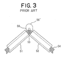
- Figure 3 illustrates an example of a conventional harness protector structure of a bending type (see Japanese Patent Application Laid-Open No. H3-15213 ).
- a pair of rectangular tube-shaped protectors 51 and 52 made of synthetic resin is bendably connected to each other with an intermediate thin one-piece hinge 53 so as to construct a harness protector, a wiring harness 54 passes through both protectors 51 and 52, and the harness protector is bent at the hinge 53 when the harness protector is conveyed while the harness protector is stretched straight and arranged when the harness protector is mounted on a vehicle.
- Figures 4A and 4B illustrate an example of a conventional harness protector structure for a link.
- a rotary link 2 is rotatably connected to a support plate 1 situated on a fixed side at a shaft part, a wiring harness 8 passes through two rectangular tube-shaped protectors 3 and 55, the protectors 3 and 55 are fastened to the support plate 1 and the link 2, respectively, so that the wiring harness 8 is rotated integrally with the link 2.
- the wiring harness 46 slackens at the intermediate shaft part 47, i.e. a connecting part 47 of both links 41 and 42, when the links 41 and 42 rotate, possibly causing an interference with the outside.
- a bent part 56 of the wiring harness 54 slackens and projects (shown with a reference numeral 56' in Fig. 3 ) at the hinge 53 when the protectors 51 and 52 are bent, resulting in that the slack at the bent part 56' is not removed when the protectors 51 and 52 are to be stretched straight, that is, the protectors 51 and 52 are hardly stretched straight.
- the present invention is to provide a harness protector structure for a link including:
- the slack when a slack takes place at the bent part of the wiring harness when the link is rotated, the slack is absorbed within the bulging part of the protector. Since the following part of the wiring harness, which follows the bent part of the wiring harness, enters into the bulging part, therefore a diameter of the bent part is enlarged and a bending stress applied to the bent part is reduced. Since the slack is absorbed within the bulging part of the protector, therefore the slack is prevented from projecting toward the outside and from interfering with the outside and therefore, damage of the bent part or noise due to the interference is prevented and the bending durability of the wiring harness is improved. Accordingly, the reliability of electrical conduction of the wiring harness is improved.
- a size of the opening is set up so that a minimum allowable bending diameter of the bent part of the wiring harness is ensured.
- the diameter of the bent part of the wiring harness is controlled so that the bent part does not sustain an excessive stress and the bending durability of the wiring harness is improved.
- the wiring harness passes through the bulging part, while when the link is rotated at an obtuse angle in another direction with respect to the support part, the wiring harness passes through the body part of the protector.
- Figure 1 illustrates a preferred embodiment of a harness protector structure for a link according to the present invention.
- a link 2 is connected to a perpendicular support plate (i.e. the support part) 1 at a fixed side rotatably around a shaft part (not shown in Fig. 1 ), a normal rectangular tube-shaped protector 3 is perpendicularly fixed to the support plate 1, a protector 4 having a wide opening 5 situated at one end of the protector 4 is fixed to the link 2, a wiring harness 8 is allowed to be smoothly bendable with a large radius between the opening 5 of the protector 4 situated at the link-side and an upper opening 10 of the protector 3 situated at the support plate-side, and a slack 9 of the wiring harness 8 is received within the opening 5 of the protector 4 situated at the link-side, so that the slack of the wiring harness is absorbed.
- the support plate 1 may be called a fixed link or a fixed bracket and the link 2 may be called a movable link or a rotary link.
- the protector 4 situated at the link-side includes a rectangular tube-shaped body part 7 and a hollow bulging part 6 projecting outward in a triangle shape in a front view in a direction, in which a diameter of a bent part 11 of the wiring harness 8 is widened, from one side of the body part 7 in the proximity of the shaft part of the link 2, wherein an inside space 12 of the bulging part 6 and an inside space 13 of the body part 7 communicate with each other throughout a whole length L of the bulging part 6, and the opening 5 of the bulging part 6 are widely opened toward the shaft part of the link 2.
- An opening size W of the opening 5 is set so that a bending radius for attaining the bending durability of the wiring harness 8 can be ensured.
- the bulging part 6 includes: triangle-shaped wall parts 6a, 6a parallel with each other, situated at a front side and at a rear side thereof; and an inclined shaped or bent shaped wall part 6b which connects the wall parts 6a and 6a to each other, so that the bulging part 6 has a triangle pole-shaped inside space 12 surrounded by the three walls 6a, 6a and 6b, wherein each wall part 6a continues to and is flush with a corresponding perpendicular side wall 7a of the body part 7 and the inside space 12 communicates with a square pole-shaped inside space 13 in the body part 7.
- the side wall 7a situated at the rear side is fixed to a plate surface 14 situated on a front side of the link 2.
- a rear-side wall part of the protector 3 is fixed to a front-side plate surface 15 of the support plate 1.
- An upper end (i.e. opening) 10 of the protector 3 is situated lower than an upper end 1a of the support plate 1.
- the wide opening (i.e. open end) 5 of the protector 4 of the link-side is situated nearer to a base end 2a or the shaft part of the link 2 than a distal end 2b of the link 2.
- a narrow rectangular shaped opening 16 of the distal end 2b-side of the protector 4 is situated nearer to the distal end 2b of the link 2 than the shaft part of the link 2.
- the opening 16 communicates straight with an opening 18 situated at the base end 2aside.
- the opening 18 communicates integrally with and is flush with the opening 5 of the bulging part 6.
- the link 2 rotates leftward in an obliquely downward direction.
- an angle ⁇ between the support plate 1 and the link 2 is an acute angle
- the bulging part 6 of the protector 4 is situated projecting in an obliquely upward direction
- the opening 5 of the bulging part 6 faces to an upper end-side of the support plate 1
- the wiring harness 8 is upward guided out from the protector 3 and smoothly bends leftward with a large radius, so that the wiring harness 8 is guided into the bulging part 6 from the wide opening 5 of the protector 4, guided into the body part 7 along an inner surface of the inclined shaped wall part 6b of the bulging part 6, and guided out to the outside from the opening 16 of the distal end 2b-side of the protector 4 along an inner surface of a side wall part 17 of the body part 7.
- a following part 9 of the wiring harness 8, which follows a bent part 11 of the wiring harness 8, is received in the bulging part 6 on a condition that a diameter of the following part 9 is enlarged.
- a bent part 20 having a small radius or a slack 20 projecting upward which has been seen as a typical shape of a bent wiring harness in a conventional example and is shown with a chain line in Fig. 1 , is prevented from occurring. That is, the slack 9 of the wiring harness 8 is received into the bulging part 6 from the wide opening 5 while the wiring harness 8 smoothly bends with a large radius.
- the wiring harness 8 is smoothly bent and arranged from the protector 3 of the support plate-side along an inner surface of the body part 7 of the protector 4 of the link-side.
- the wiring harness 8 passes through the bulging part 6 with the slack being absorbed while the wiring harness 8 is guided out from the body part 7 in an obliquely upward direction.
- the support plate 1 shown in Fig. 1 is upward arranged in the rear of a vehicle body corresponding to a back door rotatable up and down of a motor vehicle, the wiring harness 8 is downward arranged and connected to the vehicle body (i.e. power supply-side) from the protector 3 of the support plate-side, the following part 9 of the wiring harness 8 guided out from the protector 3 of the link-side is arranged and fixed to the back door-side, and when the back door is fully closed, as the drawing shown with a solid line in Fig. 1 , the link 2 is situated toward the rear of the vehicle in an obliquely downward direction, while when the back door is fully opened, as the drawing shown with the chain line in Fig. 4B , the link 2 is situated toward the front of the vehicle in an obliquely upward direction.
- the support plate 1 may be a part of the vehicle body.
- An application of the support plate 1 and the link 2 is not limited to the back door.
- they can be applied to opening and closing of a roof of a motor vehicle. They can also be applied to opening and closing of a slide door or a side door by arranging the support plate 1 not vertically but horizontally.
- the wiring harness 8 includes a plurality of electric wires and a harness-protecting tube (such as a bellows-type corrugated tube or a net-shaped tube).
- a plurality of electric wires may be partially wound up with a tape or a band so as to construct a wiring harness.
- the dented grooves of the corrugated tube may be engaged with and fixed to ribs provided in the protector 3 of the support plate-side or in the body part 7 of the protector 4.
- the wiring harness 8 may be fixed to an end part (except the wide opening 5) of each protector 3, 4 by winding up with a tape.
- Each protector 3, 4 may preferably be constructed in a division-type (capable of opening and closing) with a base part and a cover part for improving the workability of passing of the wiring harness 8.
- the protectors 3 and 4 can be formed with resin integrally with each other.
- Each protector 3, 4 may be formed not in rectangular tub-shape but in cylindrical shape so that the bulging part 6 of the protector 4 of the link-side is allowed to rise up from a maximum diameter part of the cylindrical shaped body part 7 so as to be formed in an inverse U-shape.
- the wiring harness 8 may be fixed to the support plate 1 by means of tightening with a band without using the protector 3 of the support plate-side.
- Fig. 1 The construction illustrated in Fig. 1 is effective not only as a harness protector structure for a link but also as a wiring harness arranging structure, a wiring harness slack absorbing structure or an electric power supplying structure.
- the link 2 and the support plate 1 may be used as an electric power supplying apparatus together with the protectors 3 and 4.
Landscapes
- Engineering & Computer Science (AREA)
- Mechanical Engineering (AREA)
- Details Of Indoor Wiring (AREA)
- Electric Cable Arrangement Between Relatively Moving Parts (AREA)
Abstract
Description
- The present invention relates to a harness protector structure for a link, in which a wiring harness is bent and arranged along a harness protector provided on a rotatable link.
-
Figure 2 illustrates an example of a conventional harness arranging structure to a link (see Japanese Patent Application Laid-Open No.2001-260770 - In this conventional structure, a pair of
links link 41 is rotatably supported by avehicle body 43 around ashaft part 44 while a base end part of anotherlink 42 is freely supported by aslide door 45, awiring harness 46 for supplying electricity is arranged along bothlinks vehicle body 43 to theslide door 45, and when theslide door 45 is opened or closed, the onelink 41 can swing back and forth in a vehicle with respect to theshaft part 44 as a fulcrum while theother link 42 can swing with respect to anintermediate shaft part 47 as a fulcrum at an angle larger than that of the onelink 41, so that the pair of thelinks slide door 45. - The
wiring harness 46 is fastened to thelink taping 48. Aconnector 49 at an end of thewiring harness 46 is connector-connected to thewiring harness 46 situated on the side of theslide door 45. Apart 50 of thewiring harness 46 guided out from an end of theother link 42 is expanded and contracted when theslide door 45 is opened and closed. -
Figure 3 illustrates an example of a conventional harness protector structure of a bending type (see Japanese Patent Application Laid-Open No.H3-15213 - In this conventional structure, a pair of rectangular tube-
shaped protectors piece hinge 53 so as to construct a harness protector, awiring harness 54 passes through bothprotectors hinge 53 when the harness protector is conveyed while the harness protector is stretched straight and arranged when the harness protector is mounted on a vehicle. -
Figures 4A and 4B illustrate an example of a conventional harness protector structure for a link. - In this conventional structure, a
rotary link 2 is rotatably connected to asupport plate 1 situated on a fixed side at a shaft part, awiring harness 8 passes through two rectangular tube-shaped protectors protectors support plate 1 and thelink 2, respectively, so that thewiring harness 8 is rotated integrally with thelink 2. - However, in the structure shown in
Fig. 2 , thewiring harness 46 slackens at theintermediate shaft part 47, i.e. a connectingpart 47 of bothlinks links Fig. 3 , abent part 56 of thewiring harness 54 slackens and projects (shown with a reference numeral 56' inFig. 3 ) at thehinge 53 when theprotectors protectors protectors - In the structure shown in
Figs. 4A and 4B , as shown inFig. 4B , when thelink 2 is used being rotated largely as much as 180 degrees, thewiring harness 8 is bent with a small radius (shown with areference numeral 20 inFig. 4B ) between theprotector 3 situated on the side of thesupport plate 1 and theprotector 55 situated on the side of thelink 2, resulting in that bending durability of thewiring harness 8 is deteriorated or that a slack of thewiring harness 8 takes place between bothprotectors - It is therefore an objective of the present invention to solve the above problems and to provide a harness protector structure for a link, by which the durability of the bent part of the wiring harness is improved and the interference with the outside is prevented when the wiring harness is rotated and bent when a link like the link as shown in
Fig. 4 is used. - In order to attain the above objective, the present invention is to provide a harness protector structure for a link including:
- a support part;
- a link rotatably connected to the support part;
- a protector provided on the link; and
- a bulging part having a wide opening opened at one end-side of a body part of the protector,
- With the construction described above, when a slack takes place at the bent part of the wiring harness when the link is rotated, the slack is absorbed within the bulging part of the protector. Since the following part of the wiring harness, which follows the bent part of the wiring harness, enters into the bulging part, therefore a diameter of the bent part is enlarged and a bending stress applied to the bent part is reduced. Since the slack is absorbed within the bulging part of the protector, therefore the slack is prevented from projecting toward the outside and from interfering with the outside and therefore, damage of the bent part or noise due to the interference is prevented and the bending durability of the wiring harness is improved. Accordingly, the reliability of electrical conduction of the wiring harness is improved.
- A size of the opening is set up so that a minimum allowable bending diameter of the bent part of the wiring harness is ensured.
- With the construction described above, the diameter of the bent part of the wiring harness is controlled so that the bent part does not sustain an excessive stress and the bending durability of the wiring harness is improved.
- When the link is rotated at an acute angle in one direction with respect to the support part, the wiring harness passes through the bulging part, while when the link is rotated at an obtuse angle in another direction with respect to the support part, the wiring harness passes through the body part of the protector.
- With the construction described above, when the link is rotated so that an angle between the support part and the link becomes acute, the slack of the wiring harness is absorbed within the bulging part of the protector and the diameter of the bent part is enlarged.
-
-
Figure 1 is a front view illustrating a preferred embodiment of a harness protector structure for a link according to the present invention; -
Figure 2 is a perspective view illustrating an example of a conventional harness arranging structure to a link; -
Figure 3 is a front view illustrating an example of a conventional harness protector structure of a bending type; and -
Figures 4A and 4B are front views illustrating an example of a conventional harness protector structure for a link at different rotation positions of the link. - In the following, the preferred embodiments of the present invention will be explained with reference to the attached drawing.
Figure 1 illustrates a preferred embodiment of a harness protector structure for a link according to the present invention. - In this harness protector structure, a
link 2 is connected to a perpendicular support plate (i.e. the support part) 1 at a fixed side rotatably around a shaft part (not shown inFig. 1 ), a normal rectangular tube-shaped protector 3 is perpendicularly fixed to thesupport plate 1, a protector 4 having awide opening 5 situated at one end of the protector 4 is fixed to thelink 2, awiring harness 8 is allowed to be smoothly bendable with a large radius between the opening 5 of the protector 4 situated at the link-side and anupper opening 10 of theprotector 3 situated at the support plate-side, and aslack 9 of thewiring harness 8 is received within the opening 5 of the protector 4 situated at the link-side, so that the slack of the wiring harness is absorbed. Thesupport plate 1 may be called a fixed link or a fixed bracket and thelink 2 may be called a movable link or a rotary link. - The protector 4 situated at the link-side includes a rectangular tube-
shaped body part 7 and a hollow bulgingpart 6 projecting outward in a triangle shape in a front view in a direction, in which a diameter of abent part 11 of thewiring harness 8 is widened, from one side of thebody part 7 in the proximity of the shaft part of thelink 2, wherein aninside space 12 of thebulging part 6 and aninside space 13 of thebody part 7 communicate with each other throughout a whole length L of thebulging part 6, and the opening 5 of thebulging part 6 are widely opened toward the shaft part of thelink 2. An opening size W of theopening 5 is set so that a bending radius for attaining the bending durability of thewiring harness 8 can be ensured. - The bulging
part 6 includes: triangle-shaped wall parts shaped wall part 6b which connects thewall parts bulging part 6 has a triangle pole-shaped insidespace 12 surrounded by the threewalls wall part 6a continues to and is flush with a correspondingperpendicular side wall 7a of thebody part 7 and theinside space 12 communicates with a square pole-shaped insidespace 13 in thebody part 7. Theside wall 7a situated at the rear side is fixed to aplate surface 14 situated on a front side of thelink 2. - A rear-side wall part of the
protector 3 is fixed to a front-side plate surface 15 of thesupport plate 1. An upper end (i.e. opening) 10 of theprotector 3 is situated lower than anupper end 1a of thesupport plate 1. The wide opening (i.e. open end) 5 of the protector 4 of the link-side is situated nearer to abase end 2a or the shaft part of thelink 2 than adistal end 2b of thelink 2. A narrow rectangularshaped opening 16 of thedistal end 2b-side of the protector 4 is situated nearer to thedistal end 2b of thelink 2 than the shaft part of thelink 2. The opening 16 communicates straight with an opening 18 situated at the base end 2aside. The opening 18 communicates integrally with and is flush with the opening 5 of thebulging part 6. - As shown in
Fig. 1 , thelink 2 rotates leftward in an obliquely downward direction. On a condition that an angle θ between thesupport plate 1 and thelink 2 is an acute angle, the bulgingpart 6 of the protector 4 is situated projecting in an obliquely upward direction, the opening 5 of the bulgingpart 6 faces to an upper end-side of thesupport plate 1, thewiring harness 8 is upward guided out from theprotector 3 and smoothly bends leftward with a large radius, so that thewiring harness 8 is guided into thebulging part 6 from thewide opening 5 of the protector 4, guided into thebody part 7 along an inner surface of the inclinedshaped wall part 6b of thebulging part 6, and guided out to the outside from the opening 16 of thedistal end 2b-side of the protector 4 along an inner surface of aside wall part 17 of thebody part 7. - Since the bulging
part 6 of the protector 4 upward projects from thewall part 17 of thebody part 7, therefore a followingpart 9 of thewiring harness 8, which follows abent part 11 of thewiring harness 8, is received in thebulging part 6 on a condition that a diameter of thefollowing part 9 is enlarged. Thereby, abent part 20 having a small radius or a slack 20 projecting upward, which has been seen as a typical shape of a bent wiring harness in a conventional example and is shown with a chain line inFig. 1 , is prevented from occurring. That is, theslack 9 of thewiring harness 8 is received into thebulging part 6 from thewide opening 5 while thewiring harness 8 smoothly bends with a large radius. - When the
link 2 is rightward rotated clockwise by about 180 degree starting from a state illustrated inFig. 1 , similarly to a drawing shown with a chain line of the right side inFig. 4B , an angle between thelink 2 and thesupport plate 1 becomes an obtuse angle. At a rotation position shown with the chain line inFig. 4B , the bulgingpart 6 of the protector 4 of the link-side inFig. 1 projects downward. - Similarly to the drawing shown with the chain line in
Fig. 4B , thewiring harness 8 is smoothly bent and arranged from theprotector 3 of the support plate-side along an inner surface of thebody part 7 of the protector 4 of the link-side. Alternatively, even on a condition that thelink 2 is rightward rotated as the drawing shown with the chain line inFig. 4B , when a slack of the wiring harness exists, thewiring harness 8 passes through the bulgingpart 6 with the slack being absorbed while thewiring harness 8 is guided out from thebody part 7 in an obliquely upward direction. - For example, the
support plate 1 shown inFig. 1 is upward arranged in the rear of a vehicle body corresponding to a back door rotatable up and down of a motor vehicle, thewiring harness 8 is downward arranged and connected to the vehicle body (i.e. power supply-side) from theprotector 3 of the support plate-side, thefollowing part 9 of thewiring harness 8 guided out from theprotector 3 of the link-side is arranged and fixed to the back door-side, and when the back door is fully closed, as the drawing shown with a solid line inFig. 1 , thelink 2 is situated toward the rear of the vehicle in an obliquely downward direction, while when the back door is fully opened, as the drawing shown with the chain line inFig. 4B , thelink 2 is situated toward the front of the vehicle in an obliquely upward direction. Thesupport plate 1 may be a part of the vehicle body. - An application of the
support plate 1 and thelink 2 is not limited to the back door. For example, they can be applied to opening and closing of a roof of a motor vehicle. They can also be applied to opening and closing of a slide door or a side door by arranging thesupport plate 1 not vertically but horizontally. - Generally, the
wiring harness 8 includes a plurality of electric wires and a harness-protecting tube (such as a bellows-type corrugated tube or a net-shaped tube). A plurality of electric wires may be partially wound up with a tape or a band so as to construct a wiring harness. - When a corrugated tube, which includes dented grooves and projecting strips arranged alternately in a circumferential direction, is used, the dented grooves of the corrugated tube may be engaged with and fixed to ribs provided in the
protector 3 of the support plate-side or in thebody part 7 of the protector 4. Alternatively, thewiring harness 8 may be fixed to an end part (except the wide opening 5) of eachprotector 3, 4 by winding up with a tape. - The
wiring harness 8 is in advance permitted to pass through theprotectors 3 and 4, then on this condition theprotectors 3 and 4 are fixed to thesupport plate 1 and thelink 2, respectively, by means of clipping or bolting. Eachprotector 3, 4 may preferably be constructed in a division-type (capable of opening and closing) with a base part and a cover part for improving the workability of passing of thewiring harness 8. - When the
support plate 1 and thelink 2 are made of not metal but synthetic resin, theprotectors 3 and 4 can be formed with resin integrally with each other. Eachprotector 3, 4 may be formed not in rectangular tub-shape but in cylindrical shape so that the bulgingpart 6 of the protector 4 of the link-side is allowed to rise up from a maximum diameter part of the cylindrical shapedbody part 7 so as to be formed in an inverse U-shape. Thewiring harness 8 may be fixed to thesupport plate 1 by means of tightening with a band without using theprotector 3 of the support plate-side. - The construction illustrated in
Fig. 1 is effective not only as a harness protector structure for a link but also as a wiring harness arranging structure, a wiring harness slack absorbing structure or an electric power supplying structure. Thelink 2 and thesupport plate 1 may be used as an electric power supplying apparatus together with theprotectors 3 and 4. - The aforementioned preferred embodiments are described to aid in understanding the present invention and variations may be made by one skilled in the art without departing from the spirit and scope of the present invention.
wherein when the link is rotated, a following part of the wiring harness, which follows a bent part of the wiring harness, passes through the bulging part from the opening, and the wiring harness is guided to the outside from the body part of the protector while a slack of the wiring harness is absorbed.
Claims (3)
- A harness protector structure for a link comprising:a support part;a link rotatably connected to the support part;a protector provided on the link; anda bulging part having a wide opening opened at one end-side of a body part of the protector,wherein a wiring harness is arranged from the support part into the protector,
wherein when the link is rotated, a following part of the wiring harness, which follows a bent part of the wiring harness, passes through the bulging part from the opening, and the wiring harness is guided to the outside from the body part of the protector while a slack of the wiring harness is absorbed. - The harness protector structure for a link according to claim 1,
wherein a size of the opening is set up so that a minimum allowable bending diameter of the bent part of the wiring harness is ensured. - The harness protector structure for a link according to claim 1,
wherein when the link is rotated at an acute angle in one direction with respect to the support part, the wiring harness passes through the bulging part, while when the link is rotated at an obtuse angle in another direction with respect to the support part, the wiring harness passes through the body part of the protector.
Applications Claiming Priority (1)
| Application Number | Priority Date | Filing Date | Title |
|---|---|---|---|
| JP2007261660A JP5026907B2 (en) | 2007-10-05 | 2007-10-05 | Harness protector structure for link |
Publications (3)
| Publication Number | Publication Date |
|---|---|
| EP2045139A2 true EP2045139A2 (en) | 2009-04-08 |
| EP2045139A3 EP2045139A3 (en) | 2010-06-09 |
| EP2045139B1 EP2045139B1 (en) | 2012-11-28 |
Family
ID=40193920
Family Applications (1)
| Application Number | Title | Priority Date | Filing Date |
|---|---|---|---|
| EP08163388A Not-in-force EP2045139B1 (en) | 2007-10-05 | 2008-09-01 | Harness protector structure for link |
Country Status (4)
| Country | Link |
|---|---|
| US (1) | US7939760B2 (en) |
| EP (1) | EP2045139B1 (en) |
| JP (1) | JP5026907B2 (en) |
| CN (1) | CN101404401B (en) |
Cited By (1)
| Publication number | Priority date | Publication date | Assignee | Title |
|---|---|---|---|---|
| EP2295295A3 (en) * | 2009-09-14 | 2013-03-13 | Yazaki Corporation | Wire Harness and Method of Installation Thereof |
Families Citing this family (8)
| Publication number | Priority date | Publication date | Assignee | Title |
|---|---|---|---|---|
| JP5101981B2 (en) * | 2007-10-17 | 2012-12-19 | 矢崎総業株式会社 | Link harness wiring structure |
| DE102009035950B4 (en) * | 2009-08-03 | 2011-09-01 | Siemens Aktiengesellschaft | Guide element for creasing hose |
| JP5373516B2 (en) * | 2009-09-11 | 2013-12-18 | 矢崎総業株式会社 | Arm feeding structure |
| JP5150678B2 (en) * | 2010-05-18 | 2013-02-20 | アルプス電気株式会社 | Detection component assembly |
| JP5892603B2 (en) * | 2012-07-17 | 2016-03-23 | 矢崎総業株式会社 | Arm feeder |
| JP6918860B2 (en) * | 2019-04-24 | 2021-08-11 | 矢崎総業株式会社 | Wire harness |
| DE102021203916A1 (en) * | 2021-04-20 | 2022-10-20 | Brose Fahrzeugteile Se & Co. Kommanditgesellschaft, Bamberg | Assembly of an adjusting device of a motor vehicle |
| US12304770B2 (en) * | 2022-11-08 | 2025-05-20 | William Hawkrigg | Coiled sheath system |
Citations (2)
| Publication number | Priority date | Publication date | Assignee | Title |
|---|---|---|---|---|
| JPH0315213A (en) | 1989-06-12 | 1991-01-23 | Yazaki Corp | protector |
| JP2001260770A (en) | 2000-03-22 | 2001-09-26 | Sumitomo Wiring Syst Ltd | Structure for laying wire harness in automobile slide door |
Family Cites Families (9)
| Publication number | Priority date | Publication date | Assignee | Title |
|---|---|---|---|---|
| US5556059A (en) * | 1993-06-28 | 1996-09-17 | Yazaki Corporation | Device for guiding wire harness of steering column |
| JP2000295733A (en) * | 1999-04-08 | 2000-10-20 | Araco Corp | Wiring harness protector |
| JP4149245B2 (en) * | 2002-10-11 | 2008-09-10 | 矢崎総業株式会社 | Power feeding device and harness wiring structure using the same |
| JP2005001560A (en) * | 2003-06-12 | 2005-01-06 | Fujikura Ltd | Harness wiring structure between vehicle body and opening / closing member |
| JP2005137082A (en) * | 2003-10-29 | 2005-05-26 | Yazaki Corp | Constant power supply device |
| US7202415B2 (en) * | 2004-10-20 | 2007-04-10 | Sumitomo Wiring Systems, Ltd. | Wire harness construction |
| JP4560478B2 (en) * | 2005-11-17 | 2010-10-13 | 矢崎総業株式会社 | Power feeding device for slide structure |
| JP2007185062A (en) * | 2006-01-10 | 2007-07-19 | Yazaki Corp | Power supply device for slide structure |
| JP5197171B2 (en) * | 2008-01-31 | 2013-05-15 | 矢崎総業株式会社 | Power supply device |
-
2007
- 2007-10-05 JP JP2007261660A patent/JP5026907B2/en not_active Expired - Fee Related
-
2008
- 2008-09-01 EP EP08163388A patent/EP2045139B1/en not_active Not-in-force
- 2008-09-12 US US12/232,207 patent/US7939760B2/en active Active
- 2008-09-24 CN CN2008101656811A patent/CN101404401B/en not_active Expired - Fee Related
Patent Citations (2)
| Publication number | Priority date | Publication date | Assignee | Title |
|---|---|---|---|---|
| JPH0315213A (en) | 1989-06-12 | 1991-01-23 | Yazaki Corp | protector |
| JP2001260770A (en) | 2000-03-22 | 2001-09-26 | Sumitomo Wiring Syst Ltd | Structure for laying wire harness in automobile slide door |
Cited By (1)
| Publication number | Priority date | Publication date | Assignee | Title |
|---|---|---|---|---|
| EP2295295A3 (en) * | 2009-09-14 | 2013-03-13 | Yazaki Corporation | Wire Harness and Method of Installation Thereof |
Also Published As
| Publication number | Publication date |
|---|---|
| JP5026907B2 (en) | 2012-09-19 |
| CN101404401B (en) | 2010-12-15 |
| EP2045139B1 (en) | 2012-11-28 |
| JP2009095105A (en) | 2009-04-30 |
| CN101404401A (en) | 2009-04-08 |
| EP2045139A3 (en) | 2010-06-09 |
| US7939760B2 (en) | 2011-05-10 |
| US20090090539A1 (en) | 2009-04-09 |
Similar Documents
| Publication | Publication Date | Title |
|---|---|---|
| EP2045139B1 (en) | Harness protector structure for link | |
| US7202415B2 (en) | Wire harness construction | |
| US7952032B2 (en) | Grommet | |
| JP4606275B2 (en) | Harness wiring structure using corrugated tube | |
| EP2050624B1 (en) | Harness routing structure for link | |
| EP1936767B1 (en) | Device for supporting cable | |
| JP5743138B2 (en) | Vehicle door harness cover | |
| WO2007029705A1 (en) | Power supply system for slide door | |
| EP2090471B1 (en) | Vehicle door with a wire harness | |
| EP1157894B1 (en) | Bellows cable grommet | |
| WO2010098189A1 (en) | Wire harness lanyard structure | |
| JP7116011B2 (en) | sliding door structure | |
| JP6276161B2 (en) | Wire harness | |
| JP4412150B2 (en) | Wiring harness wiring structure using grommets | |
| JP2009179118A (en) | Mounting structure of wire harness for feeding sliding door | |
| JP2007076620A (en) | Arranging structure of wire harness | |
| JP2006117054A (en) | Wire harness routing structure | |
| EP3885200B1 (en) | Wire harness installation structure | |
| JP4412144B2 (en) | Wiring harness wiring structure | |
| JP7740951B2 (en) | Sliding door power supply device | |
| JP2006117122A (en) | Wire harness routing structure | |
| JP7723026B2 (en) | Protectors and Wire Harnesses | |
| CN221497908U (en) | Door wiring harness bracket, door wiring harness assembly and door assembly | |
| JP4412145B2 (en) | Wire harness wiring structure | |
| JP4702849B2 (en) | Power supply device for sliding door |
Legal Events
| Date | Code | Title | Description |
|---|---|---|---|
| PUAI | Public reference made under article 153(3) epc to a published international application that has entered the european phase |
Free format text: ORIGINAL CODE: 0009012 |
|
| AK | Designated contracting states |
Kind code of ref document: A2 Designated state(s): AT BE BG CH CY CZ DE DK EE ES FI FR GB GR HR HU IE IS IT LI LT LU LV MC MT NL NO PL PT RO SE SI SK TR |
|
| AX | Request for extension of the european patent |
Extension state: AL BA MK RS |
|
| PUAL | Search report despatched |
Free format text: ORIGINAL CODE: 0009013 |
|
| AK | Designated contracting states |
Kind code of ref document: A3 Designated state(s): AT BE BG CH CY CZ DE DK EE ES FI FR GB GR HR HU IE IS IT LI LT LU LV MC MT NL NO PL PT RO SE SI SK TR |
|
| AX | Request for extension of the european patent |
Extension state: AL BA MK RS |
|
| 17P | Request for examination filed |
Effective date: 20101209 |
|
| AKX | Designation fees paid |
Designated state(s): DE FR GB IT |
|
| GRAP | Despatch of communication of intention to grant a patent |
Free format text: ORIGINAL CODE: EPIDOSNIGR1 |
|
| GRAS | Grant fee paid |
Free format text: ORIGINAL CODE: EPIDOSNIGR3 |
|
| GRAA | (expected) grant |
Free format text: ORIGINAL CODE: 0009210 |
|
| AK | Designated contracting states |
Kind code of ref document: B1 Designated state(s): DE FR GB IT |
|
| REG | Reference to a national code |
Ref country code: GB Ref legal event code: FG4D |
|
| REG | Reference to a national code |
Ref country code: DE Ref legal event code: R096 Ref document number: 602008020373 Country of ref document: DE Effective date: 20130124 |
|
| PLBE | No opposition filed within time limit |
Free format text: ORIGINAL CODE: 0009261 |
|
| STAA | Information on the status of an ep patent application or granted ep patent |
Free format text: STATUS: NO OPPOSITION FILED WITHIN TIME LIMIT |
|
| 26N | No opposition filed |
Effective date: 20130829 |
|
| REG | Reference to a national code |
Ref country code: DE Ref legal event code: R097 Ref document number: 602008020373 Country of ref document: DE Effective date: 20130829 |
|
| REG | Reference to a national code |
Ref country code: FR Ref legal event code: PLFP Year of fee payment: 9 |
|
| REG | Reference to a national code |
Ref country code: FR Ref legal event code: PLFP Year of fee payment: 10 |
|
| REG | Reference to a national code |
Ref country code: FR Ref legal event code: PLFP Year of fee payment: 11 |
|
| PGFP | Annual fee paid to national office [announced via postgrant information from national office to epo] |
Ref country code: IT Payment date: 20190917 Year of fee payment: 12 Ref country code: FR Payment date: 20190815 Year of fee payment: 12 |
|
| PGFP | Annual fee paid to national office [announced via postgrant information from national office to epo] |
Ref country code: GB Payment date: 20190830 Year of fee payment: 12 |
|
| GBPC | Gb: european patent ceased through non-payment of renewal fee |
Effective date: 20200901 |
|
| PG25 | Lapsed in a contracting state [announced via postgrant information from national office to epo] |
Ref country code: FR Free format text: LAPSE BECAUSE OF NON-PAYMENT OF DUE FEES Effective date: 20200930 |
|
| PG25 | Lapsed in a contracting state [announced via postgrant information from national office to epo] |
Ref country code: GB Free format text: LAPSE BECAUSE OF NON-PAYMENT OF DUE FEES Effective date: 20200901 |
|
| PG25 | Lapsed in a contracting state [announced via postgrant information from national office to epo] |
Ref country code: IT Free format text: LAPSE BECAUSE OF NON-PAYMENT OF DUE FEES Effective date: 20200901 |
|
| PGFP | Annual fee paid to national office [announced via postgrant information from national office to epo] |
Ref country code: DE Payment date: 20230802 Year of fee payment: 16 |
|
| REG | Reference to a national code |
Ref country code: DE Ref legal event code: R119 Ref document number: 602008020373 Country of ref document: DE |
|
| PG25 | Lapsed in a contracting state [announced via postgrant information from national office to epo] |
Ref country code: DE Free format text: LAPSE BECAUSE OF NON-PAYMENT OF DUE FEES Effective date: 20250401 |