EP2044971A1 - A balloon catheter - Google Patents
A balloon catheter Download PDFInfo
- Publication number
- EP2044971A1 EP2044971A1 EP08253149A EP08253149A EP2044971A1 EP 2044971 A1 EP2044971 A1 EP 2044971A1 EP 08253149 A EP08253149 A EP 08253149A EP 08253149 A EP08253149 A EP 08253149A EP 2044971 A1 EP2044971 A1 EP 2044971A1
- Authority
- EP
- European Patent Office
- Prior art keywords
- end portion
- distal end
- hypotube
- rear end
- core wire
- Prior art date
- Legal status (The legal status is an assumption and is not a legal conclusion. Google has not performed a legal analysis and makes no representation as to the accuracy of the status listed.)
- Withdrawn
Links
- 239000012530 fluid Substances 0.000 claims description 14
- 239000007788 liquid Substances 0.000 claims description 13
- 230000007423 decrease Effects 0.000 claims description 7
- 238000005520 cutting process Methods 0.000 claims description 3
- 210000004204 blood vessel Anatomy 0.000 description 5
- 239000000463 material Substances 0.000 description 3
- 229910045601 alloy Inorganic materials 0.000 description 2
- 239000000956 alloy Substances 0.000 description 2
- 229920001971 elastomer Polymers 0.000 description 2
- 239000000806 elastomer Substances 0.000 description 2
- 229920002647 polyamide Polymers 0.000 description 2
- 229920000728 polyester Polymers 0.000 description 2
- 238000003892 spreading Methods 0.000 description 2
- 239000010935 stainless steel Substances 0.000 description 2
- 229910001220 stainless steel Inorganic materials 0.000 description 2
- 229920003002 synthetic resin Polymers 0.000 description 2
- 239000000057 synthetic resin Substances 0.000 description 2
- 238000003466 welding Methods 0.000 description 2
- 239000004952 Polyamide Substances 0.000 description 1
- 239000008280 blood Substances 0.000 description 1
- 210000004369 blood Anatomy 0.000 description 1
- 238000005219 brazing Methods 0.000 description 1
- 238000004891 communication Methods 0.000 description 1
- 238000000034 method Methods 0.000 description 1
- 230000004048 modification Effects 0.000 description 1
- 238000012986 modification Methods 0.000 description 1
- 229920000098 polyolefin Polymers 0.000 description 1
- 238000005476 soldering Methods 0.000 description 1
- 230000000392 somatic effect Effects 0.000 description 1
- 238000004804 winding Methods 0.000 description 1
Images


Classifications
-
- A—HUMAN NECESSITIES
- A61—MEDICAL OR VETERINARY SCIENCE; HYGIENE
- A61M—DEVICES FOR INTRODUCING MEDIA INTO, OR ONTO, THE BODY; DEVICES FOR TRANSDUCING BODY MEDIA OR FOR TAKING MEDIA FROM THE BODY; DEVICES FOR PRODUCING OR ENDING SLEEP OR STUPOR
- A61M25/00—Catheters; Hollow probes
- A61M25/10—Balloon catheters
-
- A—HUMAN NECESSITIES
- A61—MEDICAL OR VETERINARY SCIENCE; HYGIENE
- A61M—DEVICES FOR INTRODUCING MEDIA INTO, OR ONTO, THE BODY; DEVICES FOR TRANSDUCING BODY MEDIA OR FOR TAKING MEDIA FROM THE BODY; DEVICES FOR PRODUCING OR ENDING SLEEP OR STUPOR
- A61M25/00—Catheters; Hollow probes
- A61M25/10—Balloon catheters
- A61M25/1025—Connections between catheter tubes and inflation tubes
-
- A—HUMAN NECESSITIES
- A61—MEDICAL OR VETERINARY SCIENCE; HYGIENE
- A61B—DIAGNOSIS; SURGERY; IDENTIFICATION
- A61B17/00—Surgical instruments, devices or methods
- A61B17/34—Trocars; Puncturing needles
-
- A—HUMAN NECESSITIES
- A61—MEDICAL OR VETERINARY SCIENCE; HYGIENE
- A61M—DEVICES FOR INTRODUCING MEDIA INTO, OR ONTO, THE BODY; DEVICES FOR TRANSDUCING BODY MEDIA OR FOR TAKING MEDIA FROM THE BODY; DEVICES FOR PRODUCING OR ENDING SLEEP OR STUPOR
- A61M25/00—Catheters; Hollow probes
-
- A—HUMAN NECESSITIES
- A61—MEDICAL OR VETERINARY SCIENCE; HYGIENE
- A61M—DEVICES FOR INTRODUCING MEDIA INTO, OR ONTO, THE BODY; DEVICES FOR TRANSDUCING BODY MEDIA OR FOR TAKING MEDIA FROM THE BODY; DEVICES FOR PRODUCING OR ENDING SLEEP OR STUPOR
- A61M25/00—Catheters; Hollow probes
- A61M25/0043—Catheters; Hollow probes characterised by structural features
- A61M25/0054—Catheters; Hollow probes characterised by structural features with regions for increasing flexibility
-
- A—HUMAN NECESSITIES
- A61—MEDICAL OR VETERINARY SCIENCE; HYGIENE
- A61M—DEVICES FOR INTRODUCING MEDIA INTO, OR ONTO, THE BODY; DEVICES FOR TRANSDUCING BODY MEDIA OR FOR TAKING MEDIA FROM THE BODY; DEVICES FOR PRODUCING OR ENDING SLEEP OR STUPOR
- A61M25/00—Catheters; Hollow probes
- A61M25/10—Balloon catheters
- A61M25/1027—Making of balloon catheters
Definitions
- the invention relates to a balloon catheter which is inserted into the somatic cavity (e.g., blood vessel and the like) to therapeutically dilate an occluded area of the blood vessel or to shut off the blood streams.
- somatic cavity e.g., blood vessel and the like
- a distal end portion of the shaft 101 has a balloon (not shown).
- a hypotube 102 of high rigidity as disclosed by Japanese Laid-open Patent Application No. 2003-164528 .
- a distal end portion 103 of the hypotube 102 is severed aslant against its axial direction, so as to gradually decrease the rigidity as approaching forward.
- a core wire 104 is provided, a distal end portion of which is inserted into the shaft 101.
- a rear end side of the core wire 104 is fixedly placed at the distal end portion 103 of the hypotube 102.
- the balloon catheter 100 upon inserting the balloon catheter 100 into the sinuous or curved blood vessel, the balloon catheter 100 has a propensity of being easily bent and broken at the boundary between the portion under the presence of the hypotube 102 and the portion under the absence of the hypotube 102.
- the structure is such that it becomes difficult to make the liquid flow in and out through the fluid passage, so as to eventually delay the dilatation and deflation of the balloon more as the core wire 104 is placed to move farther into the rear side of the hypotube 102.
- a balloon catheter which has a flexible hollow shaft, a distal end of which has a balloon.
- a hypotube is provided, a distal end portion of which is inserted into a rear end side of the shaft.
- the hypotube has a lumen which acts as a fluid passage, through which a liquid flows in the balloon and flows out of the balloon alternately.
- a core wire is provided, a distal end portion of which is inserted into a distal end side of the shaft.
- the core wire has a rear end positioned on a rear end side of the distal end portion to be fixedly inserted into the distal end portion of the hypotube.
- the distal end portion of the hypotube has a gradient opening, an open surface end of which inclines against an axial direction of the hypotube.
- a rear end portion of the core wire has a cross sectional area smaller than a cross sectional area of a rear end side of the distal end portion.
- a rear end of the core wire positionally extends at least to a rear end of the gradient opening.
- the cross sectional area of the rear end portion of the core wire determined to be smaller than the cross sectional area of the rear end side of the distal end portion, it is possible to insure a sufficient fluid passage area which permits the liquid to flow in and out through the distal end portion of the hypotube. This enables a user to achieve a smooth inflow and outflow of the liquid through the distal end portion of the hypotube, while at the same time, making it possible to place a diametrically increased core wire inside the shaft.
- the rear end portion of the core wire is tapered in registration with an open end side of the hypotube, so as to progressively decrease a diametrical width as approaching a rear end side of the hypotube. This enables the user to insure a sufficient fluid passage area at the side of the gradient opening so as to attain a smooth inflow and outflow of the liquid through the distal end portion of the hypotube.
- the rear end portion of the core wire is shaped into an angular configuration.
- the distal end portion of the hypotube has the gradient opening, the open surface end of which extends at least to a diametrical central portion of the distal end portion, and further having a planar opening formed by axially cutting the distal end portion forward at least from the diametrical central portion of the distal end portion.
- a helical hollow spring body is provided to surroundingly cover the outer surface of the gradient opening and the planar opening.
- the helical hollow spring body can compensate a reduced strength of the hypotube caused by providing the gradient opening and the planar opening.
- the helical hollow spring body prevents an open end of the planar opening from distortedly spreading in the diametrical direction when the balloon catheter is bent upon inserting the balloon catheter into the sinuous or curved blood vessel. This alleviates a bend-oriented inclination of the balloon catheter, and restrains the balloon catheter from having the propensity of being easily bent.
- the helical hollow spring body has a single wire element or a plurality of wire elements each tabular in cross section. This makes it possible to reduce a breadth of the wire element in the diametrical direction of the helical hollow spring body, so as to decrease a thickness of a wall of the helical hollow spring body.
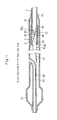
- Figs. 1 through 3 show a balloon catheter 1 according to a first embodiment of the invention.
- the balloon catheter 1 has a flexible hollow shaft 2, a hypotube 3 and a core wire 4 as shown in Fig. 1 .
- the hypotube 3 is inserted into a rear end side of the shaft 2.
- a distal end side of the core wire 4 is inserted into the shaft 2, and a rear end side of the core wire 4 is fixedly inserted into the hypotube 3.
- the shaft 2 is shaped into a tubular configuration from such materials as, for example, polyamide, polyamide-based elastomer, polyolefine, polyester or polyester-based elastomer.
- a distal end of the shaft 2 has a balloon 21.
- a guiding lumen 22 and a fluid lumen 23 are provided within the shaft 2.
- the guiding lumen 22 is to introduce a guide wire (not shown) in the shaft 2, and the fluid lumen 23 is to act as a fluid passage, through which a liquid flows in and out to alternately dilate and deflate the balloon 21.
- the hypotube 3 is shaped into a tubular configuration from such materials of high rigidity as, for example, stainless steel or superelastic alloy.
- a distal end portion 31 of the hypotube 3 is inserted into the rear end side of the shaft 2 with the hypotube 3 liquid-tightly fixed to an inner surface of a rear end of the shaft 2.
- An inner space of the hypotube 3 serves as a lumen 32 which is in communication with the fluid lumen 23 to act as a fluid path, through which the liquid flows in and out of the balloon 21 alternately.
- a distal end portion 31 of the hypotube 3 has a gradient opening 33, an open surface end of which inclines distally to angle down against an axial direction of the hypotube 3.
- An open surface end of the gradient opening 33 extends at least to a diametrical central portion of the distal end portion 31 from an outer periphery of the distal end portion 31.
- the distal end portion 31 further has a planar opening 34 formed by axially cutting the distal end portion 31 forward at least from the diametrical central portion of the hypotube 3 to an open end of the distal end portion 31.
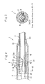
- the planar opening 34 leaves a half cylindrical portion on the distal end portion 31 of the hypotube 3 as shown in Figs. 2 and 3 .
- the core wire 4 is made from such materials as, for example, stainless steel or superelastic alloy, and having a distal end portion 41 and a rear end portion 42.
- the distal end portion 41 is tapered to be diametrically reduced as approaching forward.
- the rear end portion 42 extends from a rear end side of the distal end portion 41, and is fixedly inserted into the distal end portion 31 of the hypotube 3.
- an entire portion of the distal end portion 41 is tapered, however, an equi-diametrical portion may be partly formed inclusively in the distal end portion 41.
- the equi-diametrical portion means that its outer diameter remains unchanged along the lengthwise direction.
- the rear end portion 42 of the core wire 4 is tapered at an open end side of the hypotube 3, so as to progressively decrease a diametrical width as approaching a rear end side of the hypotube 3.
- the rear end portion 42 of the core wire 4 has a cross sectional area smaller than a cross sectional area of a boundary 43 (a rear end of the distal end portion 41) bet ween the distal end portion 41 and the rear end portion 42.
- the rear end portion 42 progressively decreases its cross sectional area as approaching rearward.
- the core wire 4 has a rear end 45 positionally extended to a rear end 33a of the gradient opening 33.
- the rear end 45 may extends rearward beyond the rear end 33a of the gradient opening 33.
- a boundary 43 is designated between the distal end portion 41 and the rear end portion 42 of the core wire 4. It is necessary to place the boundary 43 at a distal end side of the gradient opening 33 to permit a smooth liquid flow through the boundary 43.
- the boundary 43 is situated in the proximity of a front end 36 of the hypotube 3. More precisely, the boundary 43 is located slightly close to a rear side of the front end 36 of the hypotube 3.
- the rear end portion 42 of the core wire 4 is secured to an inner wall of a distal end portion 31 of the hypotube 3 by means of a heat welding procedure (e.g., laser welding, soldering, brazing or the like).
- the balloon catheter 1 has a helical hollow spring body 5 provided to surround outer surfaces of the gradient opening 33 and the planar opening 34.
- the helical hollow spring body 5 is formed by helically winding a plurality of wire elements 5a, and located at the outer surface of the hypotube 3 to cover the gradient opening 33 and the planar opening 34.
- the wire elements 5a are tabular (rectangular) in cross section.
- an inner diameter of a rear side of the shaft 2 measures 0.78 mm with an inner diameter and outer diameter of the hypotube 3 designated in turn as 0.48 mm and 0.62 mm.
- An outer diameter of the core wire 4 measures 0.45 mm at the boundary 43 between the distal end portion 41 and the rear end portion 42 of the core wire 4.
- the shaft 2 measures from 346 mm to 358 mm in length.
- the planar opening 34 measures 8 mm in length, and the gradient opening 33 measures 2 mm in length each along the axial direction of the shaft 2.
- the distal end portion 41 and the rear end portion 42 of the core wire 4 respectively measures 100 mm and 7 mm in length.
- the rear end portion 42 of the core wire 4 is tapered at the portion in which the rear end portion 42 faces the open-end portion of the hypotube 3. Namely, the rear end portion 42 is tapered in registration with the open end side of the hypotube 3 so as to be diametrically reduced progressively as approaching rearward.
- the cross sectional area of the rear end portion 42 of the core wire 4 is determined to be smaller than the cross sectional area of the boundary 43, so as to insure a sufficient fluid passage area which permits the liquid to flow in and out through the distal end portion 31 of the hypotube 3.
- This enables the user to place the diametrically increased core wire inside the shaft, so as to enhance the rigidity of the portion of the balloon catheter in which the core wire 4 resides.
- This alleviates the abrupt change of the rigidity at the boundary 43 between the portion of the balloon catheter 1 in which the hypotube 3 resides and the portion of the balloon catheter 1 in which the hypotube 3 does not reside, thus avoiding the balloon catheter 1 from having a propensity of being easily bent.
- the core wire 4 With the rear end 45 of the core wire 4 positionally extended to the rear end 33a of the gradient opening 33, there arises no place in which the core wire 4 does not reside within the gradient opening 33 located at the distal end portion 31 of the hypotube 3. Namely, the core wire 4 invariably resides inside the distal end portion 31 of the hypotube 3, so as to avoid the balloon catheter 1 from having the propensity of being easily bent.
- the helical hollow spring body 5 prevents an open end of the planar opening 34 from distortedly spreading in the diametrical direction as designated by arrows A and B in Fig. 2 when the balloon catheter 1 is bent upon inserting the balloon catheter 1 into the sinuous or curved blood vessel. This alleviates a bend-oriented inclination of the balloon catheter 1, and restrains the balloon catheter 1 from having the propensity of being easily bent.
- the wire elements 5a of the helical hollow spring body 5 being tabular in cross section, it is possible to reduce a breadth of the wire elements 5a in the diametrical direction of the helical hollow spring body 5, so as to decrease a thickness of a wall of the helical hollow spring body 5. Because of the thickness-reduced wall of the helical hollow spring body 5, it is possible to set the helical hollow spring body 5 even into a narrow interstice between an inner wall of the shaft 2 and an outer wall of the hypotube 3.
- Figs. 4 and 5 show a second embodiment of the invention in which the rear end portion 42 of the core wire 4 is angular in shape, and having a cruciform cross section.
- the rear end portion 42 of the core wire 4 has a cross sectional area smaller than a cross sectional area of the boundary 43 between the distal end portion 41 and the rear end portion 42 of the core wire 4.
- Figs. 6 and 7 show a third embodiment of the invention in which the rear end portion 42 of the core wire 4 is angular in shape, and having a cross section of a right-angled triangle.
- the rear end portion 42 of the core wire 4 has a cross sectional area smaller than a cross sectional area of the boundary 43 between the distal end portion 41 and the rear end portion 42 of the core wire 4.
- Figs. 8 and 9 show a fourth embodiment of the invention in which the rear end portion 42 of the core wire 4 is angular in shape, and having a Y-shaped cross section.
- the rear end portion 42 of the core wire 4 has a cross sectional area smaller than a cross sectional area of the boundary 43 between the distal end portion 41 and the rear end portion 42 of the core wire 4.
Landscapes
- Health & Medical Sciences (AREA)
- Life Sciences & Earth Sciences (AREA)
- Heart & Thoracic Surgery (AREA)
- Animal Behavior & Ethology (AREA)
- Veterinary Medicine (AREA)
- Public Health (AREA)
- Engineering & Computer Science (AREA)
- Biomedical Technology (AREA)
- General Health & Medical Sciences (AREA)
- Anesthesiology (AREA)
- Hematology (AREA)
- Pulmonology (AREA)
- Biophysics (AREA)
- Child & Adolescent Psychology (AREA)
- Surgery (AREA)
- Pathology (AREA)
- Nuclear Medicine, Radiotherapy & Molecular Imaging (AREA)
- Medical Informatics (AREA)
- Molecular Biology (AREA)
- Media Introduction/Drainage Providing Device (AREA)
Abstract
Description
- The invention relates to a balloon catheter which is inserted into the somatic cavity (e.g., blood vessel and the like) to therapeutically dilate an occluded area of the blood vessel or to shut off the blood streams.
- In a
prior balloon catheter 100 which has aflexible shaft 101 as shown inFigs. 10 and 11 , a distal end portion of theshaft 101 has a balloon (not shown). To a rear end side of theshaft 101, connected is ahypotube 102 of high rigidity as disclosed by Japanese Laid-open Patent Application No.2003-164528 - In order to alleviate an abrupt change of rigidity occurred between the
hypotube 102 and theshaft 101, adistal end portion 103 of thehypotube 102 is severed aslant against its axial direction, so as to gradually decrease the rigidity as approaching forward. Acore wire 104 is provided, a distal end portion of which is inserted into theshaft 101. A rear end side of thecore wire 104 is fixedly placed at thedistal end portion 103 of thehypotube 102. - In the above balloon catheter, it is necessary to diametrically reduce the
core wire 104 so as to insure a sufficient cross sectional area for a fluid passage between the rear end side of thecore wire 104 and thedistal end portion 103 of thehypotube 102 when injecting a liquid flowing through the fluid passage to therapeutically dilate the balloon. - For this reason, it is still difficult to enhance the rigidity of the portion of the
balloon catheter 100 in which only thecore wire 104 resides under the absence of thehypotube 102. This yet retains the sharp change of the rigidity at the boundary between the portion of theballoon catheter 100 in which thehypotube 102 resides and the portion of theballoon catheter 100 in which thehypotube 102 is absent. - In this situation, upon inserting the
balloon catheter 100 into the sinuous or curved blood vessel, theballoon catheter 100 has a propensity of being easily bent and broken at the boundary between the portion under the presence of thehypotube 102 and the portion under the absence of thehypotube 102. - The structure is such that it becomes difficult to make the liquid flow in and out through the fluid passage, so as to eventually delay the dilatation and deflation of the balloon more as the
core wire 104 is placed to move farther into the rear side of thehypotube 102. - In order to avoid the delay of the dilatation and deflation of the balloon due to the restricted liquid flow, it is necessary to place a
rear end 106 of thecore wire 104 at a half way of the slantingly severedend 103 of thehypotube 102. - In this case, there arises a
portion 108 in which thecore wire 104 does not reside at the slantingly severedend 103. Due to a greater rigidity difference appeared between theportion 108 and aportion 109 in which thecore wire 104 resides at the slantinglysevered end 103, theballoon catheter 100 still has the propensity of being easily bent. - Therefore, it is an object of the invention to overcome the above drawbacks so as to provide a balloon catheter which has a hypotube at a rear side of a flexible hollow shaft, and is capable to avoid the balloon catheter from having a propensity of being easily bent.
- According to the present invention, there is provided a balloon catheter which has a flexible hollow shaft, a distal end of which has a balloon. A hypotube is provided, a distal end portion of which is inserted into a rear end side of the shaft. The hypotube has a lumen which acts as a fluid passage, through which a liquid flows in the balloon and flows out of the balloon alternately.
- A core wire is provided, a distal end portion of which is inserted into a distal end side of the shaft. The core wire has a rear end positioned on a rear end side of the distal end portion to be fixedly inserted into the distal end portion of the hypotube. The distal end portion of the hypotube has a gradient opening, an open surface end of which inclines against an axial direction of the hypotube.
- A rear end portion of the core wire has a cross sectional area smaller than a cross sectional area of a rear end side of the distal end portion. A rear end of the core wire positionally extends at least to a rear end of the gradient opening.
- With the cross sectional area of the rear end portion of the core wire determined to be smaller than the cross sectional area of the rear end side of the distal end portion, it is possible to insure a sufficient fluid passage area which permits the liquid to flow in and out through the distal end portion of the hypotube. This enables a user to achieve a smooth inflow and outflow of the liquid through the distal end portion of the hypotube, while at the same time, making it possible to place a diametrically increased core wire inside the shaft.
- As a result, it becomes possible to enhance the rigidity of the portion of the balloon catheter in which the core wire resides under the absence of the hypotube. This alleviates an abrupt change of the rigidity at the boundary between the portion of the balloon catheter in which the hypotube resides and the portion of the balloon catheter in which the hypotube does not reside, thus avoiding the balloon catheter from having a propensity of being easily bent.
- With the rear end of the core wire positionally extended at least to the rear end of the gradient opening, there arises no place in which the core wire does not reside within the gradient opening located at the distal end portion of the hypotube. Even from this point of view, it is possible to avoid the balloon catheter from having the propensity of being easily bent.
- According to other aspect of the invention, the rear end portion of the core wire is tapered in registration with an open end side of the hypotube, so as to progressively decrease a diametrical width as approaching a rear end side of the hypotube. This enables the user to insure a sufficient fluid passage area at the side of the gradient opening so as to attain a smooth inflow and outflow of the liquid through the distal end portion of the hypotube.
- According to other aspect of the invention, the rear end portion of the core wire is shaped into an angular configuration.
- According to other aspect of the invention, the distal end portion of the hypotube has the gradient opening, the open surface end of which extends at least to a diametrical central portion of the distal end portion, and further having a planar opening formed by axially cutting the distal end portion forward at least from the diametrical central portion of the distal end portion.
- According to other aspect of the invention, a helical hollow spring body is provided to surroundingly cover the outer surface of the gradient opening and the planar opening.
- The helical hollow spring body can compensate a reduced strength of the hypotube caused by providing the gradient opening and the planar opening. The helical hollow spring body prevents an open end of the planar opening from distortedly spreading in the diametrical direction when the balloon catheter is bent upon inserting the balloon catheter into the sinuous or curved blood vessel. This alleviates a bend-oriented inclination of the balloon catheter, and restrains the balloon catheter from having the propensity of being easily bent.
- According to other aspect of the invention, the helical hollow spring body has a single wire element or a plurality of wire elements each tabular in cross section. This makes it possible to reduce a breadth of the wire element in the diametrical direction of the helical hollow spring body, so as to decrease a thickness of a wall of the helical hollow spring body.
- A non-limiting example of the present invention is illustrated in the accompanying drawings in which:
-
Fig. 1 is a longitudinal cross sectional view of a balloon catheter according to a first embodiment of the invention; -
Fig. 2 is a longitudinal cross sectional view of a main portion of the balloon catheter; -
Fig. 3 is a latitudinal cross sectional view taken along the line III-III ofFig. 2 ; -
Fig. 4 is a plan view of a core wire according to a second embodiment of the invention; -
Fig. 5 is a side elevational view of the core wire according to the second embodiment of the invention; -
Fig. 6 is a plan view of the core wire according to a third embodiment of the invention; -
Fig. 7 is a side elevational view of the core wire according to the third embodiment of the invention; -
Fig. 8 is a plan view of the core wire according to a fourth embodiment of the invention; -
Fig. 9 is a side elevational view of the core wire according to the fourth embodiment of the invention; -
Fig. 10 is a longitudinal cross sectional view of a prior balloon catheter; and -
Fig. 11 is a latitudinal cross sectional view taken along the line XI-XI ofFig. 10 . - In the following description of the depicted embodiments, the same reference numerals are used for features of the same type.
- Referring to
Figs. 1 through 3 which show a balloon catheter 1 according to a first embodiment of the invention. The balloon catheter 1 has a flexiblehollow shaft 2, ahypotube 3 and acore wire 4 as shown inFig. 1 . - The
hypotube 3 is inserted into a rear end side of theshaft 2. A distal end side of thecore wire 4 is inserted into theshaft 2, and a rear end side of thecore wire 4 is fixedly inserted into thehypotube 3. - The
shaft 2 is shaped into a tubular configuration from such materials as, for example, polyamide, polyamide-based elastomer, polyolefine, polyester or polyester-based elastomer. A distal end of theshaft 2 has aballoon 21. Within theshaft 2, a guidinglumen 22 and afluid lumen 23 are provided. The guidinglumen 22 is to introduce a guide wire (not shown) in theshaft 2, and thefluid lumen 23 is to act as a fluid passage, through which a liquid flows in and out to alternately dilate and deflate theballoon 21. - The
hypotube 3 is shaped into a tubular configuration from such materials of high rigidity as, for example, stainless steel or superelastic alloy. Adistal end portion 31 of thehypotube 3 is inserted into the rear end side of theshaft 2 with thehypotube 3 liquid-tightly fixed to an inner surface of a rear end of theshaft 2. An inner space of thehypotube 3 serves as alumen 32 which is in communication with thefluid lumen 23 to act as a fluid path, through which the liquid flows in and out of theballoon 21 alternately. - A
distal end portion 31 of thehypotube 3 has a gradient opening 33, an open surface end of which inclines distally to angle down against an axial direction of thehypotube 3. An open surface end of thegradient opening 33 extends at least to a diametrical central portion of thedistal end portion 31 from an outer periphery of thedistal end portion 31. - The
distal end portion 31 further has aplanar opening 34 formed by axially cutting thedistal end portion 31 forward at least from the diametrical central portion of thehypotube 3 to an open end of thedistal end portion 31. - The
planar opening 34 leaves a half cylindrical portion on thedistal end portion 31 of thehypotube 3 as shown inFigs. 2 and 3 . - The
core wire 4 is made from such materials as, for example, stainless steel or superelastic alloy, and having adistal end portion 41 and arear end portion 42. Thedistal end portion 41 is tapered to be diametrically reduced as approaching forward. Therear end portion 42 extends from a rear end side of thedistal end portion 41, and is fixedly inserted into thedistal end portion 31 of thehypotube 3. - In the embodiment of the invention, an entire portion of the
distal end portion 41 is tapered, however, an equi-diametrical portion may be partly formed inclusively in thedistal end portion 41. The equi-diametrical portion means that its outer diameter remains unchanged along the lengthwise direction. Therear end portion 42 of thecore wire 4 is tapered at an open end side of thehypotube 3, so as to progressively decrease a diametrical width as approaching a rear end side of thehypotube 3. - With the result that the
rear end portion 42 is tapered, therear end portion 42 of thecore wire 4 has a cross sectional area smaller than a cross sectional area of a boundary 43 (a rear end of the distal end portion 41) bet ween thedistal end portion 41 and therear end portion 42. Therear end portion 42 progressively decreases its cross sectional area as approaching rearward. - The
core wire 4 has arear end 45 positionally extended to arear end 33a of thegradient opening 33. Therear end 45 may extends rearward beyond therear end 33a of thegradient opening 33. - A
boundary 43 is designated between thedistal end portion 41 and therear end portion 42 of thecore wire 4. It is necessary to place theboundary 43 at a distal end side of thegradient opening 33 to permit a smooth liquid flow through theboundary 43. - In this instance, the
boundary 43 is situated in the proximity of afront end 36 of thehypotube 3. More precisely, theboundary 43 is located slightly close to a rear side of thefront end 36 of thehypotube 3. - The
rear end portion 42 of thecore wire 4 is secured to an inner wall of adistal end portion 31 of thehypotube 3 by means of a heat welding procedure (e.g., laser welding, soldering, brazing or the like). The balloon catheter 1 has a helicalhollow spring body 5 provided to surround outer surfaces of thegradient opening 33 and theplanar opening 34. The helicalhollow spring body 5 is formed by helically winding a plurality ofwire elements 5a, and located at the outer surface of thehypotube 3 to cover thegradient opening 33 and theplanar opening 34. Thewire elements 5a are tabular (rectangular) in cross section. - By way of illustration, an inner diameter of a rear side of the
shaft 2 measures 0.78 mm with an inner diameter and outer diameter of thehypotube 3 designated in turn as 0.48 mm and 0.62 mm. An outer diameter of thecore wire 4 measures 0.45 mm at theboundary 43 between thedistal end portion 41 and therear end portion 42 of thecore wire 4. Depending on a length of theballoon 21 , theshaft 2 measures from 346 mm to 358 mm in length. - The
planar opening 34 measures 8 mm in length, and the gradient opening 33measures 2 mm in length each along the axial direction of theshaft 2. Thedistal end portion 41 and therear end portion 42 of thecore wire 4 respectively measures 100 mm and 7 mm in length. - With the structure thus far described, the
rear end portion 42 of thecore wire 4 is tapered at the portion in which therear end portion 42 faces the open-end portion of thehypotube 3. Namely, therear end portion 42 is tapered in registration with the open end side of thehypotube 3 so as to be diametrically reduced progressively as approaching rearward. - With the result that the
rear end portion 42 is tapered, the cross sectional area of therear end portion 42 of thecore wire 4 is determined to be smaller than the cross sectional area of theboundary 43, so as to insure a sufficient fluid passage area which permits the liquid to flow in and out through thedistal end portion 31 of thehypotube 3. - With the above structure, it is possible to achieve a smooth inflow and outflow of the liquid through the
distal end portion 31 of thehypotube 3, while at the same time, permitting to set a diametrically increased core wire inside theshaft 2. - This enables the user to place the diametrically increased core wire inside the shaft, so as to enhance the rigidity of the portion of the balloon catheter in which the
core wire 4 resides. This alleviates the abrupt change of the rigidity at theboundary 43 between the portion of the balloon catheter 1 in which thehypotube 3 resides and the portion of the balloon catheter 1 in which thehypotube 3 does not reside, thus avoiding the balloon catheter 1 from having a propensity of being easily bent. - With the
rear end 45 of thecore wire 4 positionally extended to therear end 33a of thegradient opening 33, there arises no place in which thecore wire 4 does not reside within thegradient opening 33 located at thedistal end portion 31 of thehypotube 3. Namely, thecore wire 4 invariably resides inside thedistal end portion 31 of thehypotube 3, so as to avoid the balloon catheter 1 from having the propensity of being easily bent. - With the helical
hollow spring body 5 provided to surroundingly cover thegradient opening 33 and theplanar opening 34, it is possible to compensate a reduced strength of thehypotube 3 caused by providing thegradient opening 33 and theplanar opening 34. - The helical
hollow spring body 5 prevents an open end of theplanar opening 34 from distortedly spreading in the diametrical direction as designated by arrows A and B inFig. 2 when the balloon catheter 1 is bent upon inserting the balloon catheter 1 into the sinuous or curved blood vessel. This alleviates a bend-oriented inclination of the balloon catheter 1, and restrains the balloon catheter 1 from having the propensity of being easily bent. - With the
wire elements 5a of the helicalhollow spring body 5 being tabular in cross section, it is possible to reduce a breadth of thewire elements 5a in the diametrical direction of the helicalhollow spring body 5, so as to decrease a thickness of a wall of the helicalhollow spring body 5. Because of the thickness-reduced wall of the helicalhollow spring body 5, it is possible to set the helicalhollow spring body 5 even into a narrow interstice between an inner wall of theshaft 2 and an outer wall of thehypotube 3. -
Figs. 4 and 5 show a second embodiment of the invention in which therear end portion 42 of thecore wire 4 is angular in shape, and having a cruciform cross section. Therear end portion 42 of thecore wire 4 has a cross sectional area smaller than a cross sectional area of theboundary 43 between thedistal end portion 41 and therear end portion 42 of thecore wire 4. -
Figs. 6 and 7 show a third embodiment of the invention in which therear end portion 42 of thecore wire 4 is angular in shape, and having a cross section of a right-angled triangle. Therear end portion 42 of thecore wire 4 has a cross sectional area smaller than a cross sectional area of theboundary 43 between thedistal end portion 41 and therear end portion 42 of thecore wire 4. -
Figs. 8 and 9 show a fourth embodiment of the invention in which therear end portion 42 of thecore wire 4 is angular in shape, and having a Y-shaped cross section. Therear end portion 42 of thecore wire 4 has a cross sectional area smaller than a cross sectional area of theboundary 43 between thedistal end portion 41 and therear end portion 42 of thecore wire 4. - According to the second, third and fourth embodiments of the invention, it is possible to insure a sufficient space as the fluid passage between the
core wire 4 and an inner wall of thehypotube 3. -
- (a) Upon forming the
gradient opening 33, thedistal end portion 31 of thehypotube 3 may be cut slantwisely to extend to a distal open end of thehypotube 3 without providing theplanar opening 34. - (b) Instead of providing the plurality of the
wire elements 5a to form the helicalhollow spring body 5, only one single wire element may be provided to form the helicalhollow spring body 5.
It is, however, preferable to use the plurality of thewire elements 5a because they reinforce the physical strength of the helicalhollow spring body 5. - (c) Upon providing the
shaft 2 in which thecore wire 4, thehypotube 3 and the helicalhollow spring body 5 are provided, a molten synthetic resin (not shown) may be poured into helical interstices between thewire elements 5a of the helicalhollow spring body 5, so as to form the helicalhollow spring body 5, the interstices of which are filled by the synthetic resin. This makes the balloon catheter 1 preferably resist against an expansile force because the helicalhollow spring body 5 is strengthened at its stretch-oriented resistance.
Claims (6)
- A balloon catheter (1) which has a flexible hollow shaft (2), a distal end of which has a balloon (21);
characterized in that,
a hypotube (3) is provided, a distal end portion (31) of which is inserted into a rear end side of said shaft (2), said hypotube (3) having a lumen (32) which acts as a fluid passage, through which a liquid flows in said balloon (21) and flows out of said balloon (21) alternately;
a core wire (4) is provided, a distal end portion (41) of which is inserted into a distal end side of said shaft (2), said core wire (4) having a rear end portion (4 2) positioned on a rear end side of said distal end portion (41) to be fixedly inserted into said distal end portion (31) of said hypotube (3);
said distal end portion (31) of said hypotube (3) has a gradient opening (33), an open surface end of which inclines against an axial direction thereof;
said rear end portion (42) of said core wire (4) has a cross sectional area smaller then a cross sectional area of a rear end side of said distal end portion (41); and
a rear end (45) of said core wire (4) positionally extends at least to a rear end (33a) of said gradient opening (33). - The balloon catheter (1) according to claim 1, wherein said rear end portion (42) of said core wire (4) is tapered in registration with an open end side of said hypotube (3), so that a diametrical width progressively decreases as approaching a rear end side of said hypotube (3).
- The balloon catheter (1) according to claim 1, wherein said rear end portion (42) of said core wire (4) is shaped into an angular configuration.
- The balloon catheter (1) according to any of claims 1-3, wherein said distal end portion (31) of said hypotube (3) comprises said gradient opening (33), the open surface end of which extends at least to a diametrical central portion of said distal end portion (31), and a planar opening (34) formed by axially cutting said distal end portion (31) forward at least from said diametrical central portion thereof.
- The balloon catheter (1) according to claim 4, wherein a helical hollow spring body (5) is provided to surroundingly cover said outer surface of said gradient opening (33) and said planar opening (34).
- The balloon catheter (1) according to claim 5, wherein said helical hollow spring body (5) has a single wire element or a plurality of wire elements (5a) each tabular in cross section.
Applications Claiming Priority (1)
| Application Number | Priority Date | Filing Date | Title |
|---|---|---|---|
| JP2007261445A JP2009089806A (en) | 2007-10-05 | 2007-10-05 | Balloon catheter |
Publications (1)
| Publication Number | Publication Date |
|---|---|
| EP2044971A1 true EP2044971A1 (en) | 2009-04-08 |
Family
ID=40289341
Family Applications (1)
| Application Number | Title | Priority Date | Filing Date |
|---|---|---|---|
| EP08253149A Withdrawn EP2044971A1 (en) | 2007-10-05 | 2008-09-26 | A balloon catheter |
Country Status (4)
| Country | Link |
|---|---|
| EP (1) | EP2044971A1 (en) |
| JP (1) | JP2009089806A (en) |
| KR (1) | KR20090035429A (en) |
| CN (1) | CN101422637A (en) |
Cited By (2)
| Publication number | Priority date | Publication date | Assignee | Title |
|---|---|---|---|---|
| CN102274575A (en) * | 2011-05-17 | 2011-12-14 | 微创医疗器械(上海)有限公司 | Balloon dilatation catheter |
| USD1115794S1 (en) | 2022-06-23 | 2026-03-03 | Biosense Webster (Israel) Ltd. | Display screen with GUI for contact quality indicator of expandable end effectors in computer-aided electrophysiology navigation |
Families Citing this family (27)
| Publication number | Priority date | Publication date | Assignee | Title |
|---|---|---|---|---|
| EP2714180B1 (en) * | 2011-05-26 | 2018-11-07 | Abbott Cardiovascular Systems Inc. | Catheter with stepped skived hypotube |
| JP5580279B2 (en) * | 2011-11-29 | 2014-08-27 | 日本ライフライン株式会社 | Balloon catheter |
| JP5917279B2 (en) * | 2012-05-07 | 2016-05-11 | 株式会社グッドマン | Medical shaft and medical instrument |
| CN103191512B (en) * | 2013-04-15 | 2014-06-11 | 业聚医疗器械(深圳)有限公司 | Quick exchanging balloon catheter structure |
| JP6320007B2 (en) * | 2013-11-29 | 2018-05-09 | フクダ電子株式会社 | Balloon catheter |
| CN106823108B (en) * | 2015-12-04 | 2023-06-06 | 易生科技(北京)有限公司 | a hypotube |
| US10660700B2 (en) * | 2016-04-28 | 2020-05-26 | Biosense Webster (Israel) Ltd. | Irrigated balloon catheter with flexible circuit electrode assembly |
| US10905329B2 (en) | 2016-06-09 | 2021-02-02 | Biosense Webster (Israel) Ltd. | Multi-function conducting elements for a catheter |
| US11400205B2 (en) | 2016-11-23 | 2022-08-02 | Biosense Webster (Israel) Ltd. | Balloon-in-balloon irrigation balloon catheter |
| US12029545B2 (en) | 2017-05-30 | 2024-07-09 | Biosense Webster (Israel) Ltd. | Catheter splines as location sensors |
| US12102781B2 (en) | 2018-06-29 | 2024-10-01 | Biosense Webster (Israel) Ltd. | Reinforcement for irrigated electrophysiology balloon catheter with flexible-circuit electrodes |
| US12458436B2 (en) | 2018-07-30 | 2025-11-04 | Biosense Webster (Israel) Ltd. | Flexible-circuit tip for a split-tip catheter |
| US11071585B2 (en) | 2018-09-14 | 2021-07-27 | Biosense Webster (Israel) Ltd. | Systems and methods of ablating cardiac tissue |
| US12616515B2 (en) | 2019-08-27 | 2026-05-05 | Biosense Webster (Israel) Ltd. | Estimation of electrode-tissue contact using stem and edge electrodes |
| US12369975B2 (en) | 2019-09-12 | 2025-07-29 | Biosense Webster (Israel) Ltd. | Balloon catheter with force sensor |
| US11633228B2 (en) | 2019-10-04 | 2023-04-25 | Biosense Webster (Israel) Ltd. | Identifying pulmonary vein occlusion by dimension deformations of balloon catheter |
| US12369974B2 (en) | 2019-10-10 | 2025-07-29 | Biosense Webster (Israel) Ltd. | Touch indication of balloon-catheter ablation electrode via balloon surface temperature measurement |
| US12137967B2 (en) | 2019-11-12 | 2024-11-12 | Biosense Webster (Israel) Ltd. | Accurate positioning and shape visualization of balloon catheter ablation tags |
| US12558154B2 (en) | 2020-08-14 | 2026-02-24 | Biosense Webster (Israel) Ltd. | Balloon catheter having ablation and return electrodes |
| US12239364B2 (en) | 2020-10-07 | 2025-03-04 | Biosense Webster (Israel) Ltd. | Printed proximal electrodes of an expandable catheter for use as a common electrode |
| US11974803B2 (en) | 2020-10-12 | 2024-05-07 | Biosense Webster (Israel) Ltd. | Basket catheter with balloon |
| US12544128B2 (en) | 2020-10-30 | 2026-02-10 | Biosense Webster (Israel) Ltd. | Balloon catheter with split electrodes |
| US11957852B2 (en) | 2021-01-14 | 2024-04-16 | Biosense Webster (Israel) Ltd. | Intravascular balloon with slidable central irrigation tube |
| US11849995B2 (en) | 2021-02-18 | 2023-12-26 | Biosense Webster (Israel) Ltd. | Detection of balloon catheter tissue contact using optical measurement |
| US12114905B2 (en) | 2021-08-27 | 2024-10-15 | Biosense Webster (Israel) Ltd. | Reinforcement and stress relief for an irrigated electrophysiology balloon catheter with flexible-circuit electrodes |
| CN114010921A (en) * | 2021-12-10 | 2022-02-08 | 深圳北芯生命科技股份有限公司 | Extension guide catheter |
| US12551270B2 (en) | 2022-06-23 | 2026-02-17 | Biosense Webster (Israel) Ltd. | Graphical contact quality indicator for balloon catheter navigation |
Citations (4)
| Publication number | Priority date | Publication date | Assignee | Title |
|---|---|---|---|---|
| WO1995026774A1 (en) * | 1994-04-01 | 1995-10-12 | Advanced Cardiovascular Systems, Inc. | Double balloon catheter assembly |
| US5785685A (en) * | 1994-09-16 | 1998-07-28 | Scimed Life Systems, Inc. | Balloon catheter with improved pressure source |
| US20010011180A1 (en) * | 1996-10-24 | 2001-08-02 | Ave Connaught | Reinforced monorail balloon catheter |
| JP2003164528A (en) | 2001-11-29 | 2003-06-10 | Nippon Sherwood Medical Industries Ltd | Balloon catheter |
Family Cites Families (4)
| Publication number | Priority date | Publication date | Assignee | Title |
|---|---|---|---|---|
| JP2000116788A (en) * | 1998-10-16 | 2000-04-25 | Piolax Inc | Catheter |
| US7169162B2 (en) * | 2002-07-03 | 2007-01-30 | Orbusneich Medical, Inc. | Balloon catheter |
| US20050070879A1 (en) * | 2003-09-26 | 2005-03-31 | Medtronic Vascular, Inc | Transition section for a catheter |
| JP4535868B2 (en) * | 2004-12-28 | 2010-09-01 | テルモ株式会社 | catheter |
-
2007
- 2007-10-05 JP JP2007261445A patent/JP2009089806A/en active Pending
-
2008
- 2008-09-26 EP EP08253149A patent/EP2044971A1/en not_active Withdrawn
- 2008-09-30 KR KR1020080095924A patent/KR20090035429A/en not_active Withdrawn
- 2008-10-06 CN CNA2008101661909A patent/CN101422637A/en active Pending
Patent Citations (4)
| Publication number | Priority date | Publication date | Assignee | Title |
|---|---|---|---|---|
| WO1995026774A1 (en) * | 1994-04-01 | 1995-10-12 | Advanced Cardiovascular Systems, Inc. | Double balloon catheter assembly |
| US5785685A (en) * | 1994-09-16 | 1998-07-28 | Scimed Life Systems, Inc. | Balloon catheter with improved pressure source |
| US20010011180A1 (en) * | 1996-10-24 | 2001-08-02 | Ave Connaught | Reinforced monorail balloon catheter |
| JP2003164528A (en) | 2001-11-29 | 2003-06-10 | Nippon Sherwood Medical Industries Ltd | Balloon catheter |
Cited By (3)
| Publication number | Priority date | Publication date | Assignee | Title |
|---|---|---|---|---|
| CN102274575A (en) * | 2011-05-17 | 2011-12-14 | 微创医疗器械(上海)有限公司 | Balloon dilatation catheter |
| CN102274575B (en) * | 2011-05-17 | 2013-07-17 | 上海微创医疗器械(集团)有限公司 | Balloon dilatation catheter |
| USD1115794S1 (en) | 2022-06-23 | 2026-03-03 | Biosense Webster (Israel) Ltd. | Display screen with GUI for contact quality indicator of expandable end effectors in computer-aided electrophysiology navigation |
Also Published As
| Publication number | Publication date |
|---|---|
| KR20090035429A (en) | 2009-04-09 |
| CN101422637A (en) | 2009-05-06 |
| JP2009089806A (en) | 2009-04-30 |
Similar Documents
| Publication | Publication Date | Title |
|---|---|---|
| US10315018B2 (en) | Catheter shaft designs | |
| TWI774832B (en) | Catheter and catheter kit | |
| JP5954748B2 (en) | catheter | |
| EP2389973A1 (en) | Balloon catheter | |
| EP2517749A1 (en) | Catheter | |
| KR20090035429A (en) | Inflatable catheter | |
| US20080097247A1 (en) | Medical device including structure for crossing an occlusion in a vessel | |
| JP6207902B2 (en) | catheter | |
| US9211389B2 (en) | Offset soft tip with proposed tooling | |
| US20080183182A1 (en) | Guide wire | |
| JP5631475B1 (en) | Balloon catheter | |
| US20120065621A1 (en) | Double lumen tubing with improved kinking resistance | |
| EP3088036A1 (en) | Balloon catheter | |
| JP2001333984A (en) | Balloon catheter | |
| EP2762192A1 (en) | Balloon catheter | |
| JP4754843B2 (en) | catheter | |
| US11511085B2 (en) | Torque coil and method | |
| HK1126699A (en) | A balloon catheter | |
| JP5997370B2 (en) | Guide wire | |
| JP5618421B2 (en) | Balloon catheter | |
| JP2006102024A (en) | Catheter with slit side holes | |
| WO2018092354A1 (en) | Balloon catheter | |
| JP2023006823A (en) | balloon catheter |
Legal Events
| Date | Code | Title | Description |
|---|---|---|---|
| PUAI | Public reference made under article 153(3) epc to a published international application that has entered the european phase |
Free format text: ORIGINAL CODE: 0009012 |
|
| AK | Designated contracting states |
Kind code of ref document: A1 Designated state(s): AT BE BG CH CY CZ DE DK EE ES FI FR GB GR HR HU IE IS IT LI LT LU LV MC MT NL NO PL PT RO SE SI SK TR |
|
| AX | Request for extension of the european patent |
Extension state: AL BA MK RS |
|
| 17P | Request for examination filed |
Effective date: 20090602 |
|
| 17Q | First examination report despatched |
Effective date: 20090701 |
|
| REG | Reference to a national code |
Ref country code: HK Ref legal event code: DE Ref document number: 1126699 Country of ref document: HK |
|
| AKX | Designation fees paid |
Designated state(s): AT BE BG CH CY CZ DE DK EE ES FI FR GB GR HR HU IE IS IT LI LT LU LV MC MT NL NO PL PT RO SE SI SK TR |
|
| STAA | Information on the status of an ep patent application or granted ep patent |
Free format text: STATUS: THE APPLICATION IS DEEMED TO BE WITHDRAWN |
|
| 18D | Application deemed to be withdrawn |
Effective date: 20120403 |
|
| REG | Reference to a national code |
Ref country code: HK Ref legal event code: WD Ref document number: 1126699 Country of ref document: HK |