EP2044899A2 - Trokaranordnung ohne Klinge mit zwei Modi - Google Patents
Trokaranordnung ohne Klinge mit zwei Modi Download PDFInfo
- Publication number
- EP2044899A2 EP2044899A2 EP20080253235 EP08253235A EP2044899A2 EP 2044899 A2 EP2044899 A2 EP 2044899A2 EP 20080253235 EP20080253235 EP 20080253235 EP 08253235 A EP08253235 A EP 08253235A EP 2044899 A2 EP2044899 A2 EP 2044899A2
- Authority
- EP
- European Patent Office
- Prior art keywords
- obturator
- shield
- housing
- bladeless
- assembly
- Prior art date
- Legal status (The legal status is an assumption and is not a legal conclusion. Google has not performed a legal analysis and makes no representation as to the accuracy of the status listed.)
- Withdrawn
Links
- 230000000149 penetrating effect Effects 0.000 claims abstract description 55
- 230000035515 penetration Effects 0.000 claims abstract description 6
- 238000012790 confirmation Methods 0.000 claims description 10
- 230000000007 visual effect Effects 0.000 claims description 8
- 230000013011 mating Effects 0.000 claims description 5
- 239000012190 activator Substances 0.000 description 48
- 238000000034 method Methods 0.000 description 10
- 239000000463 material Substances 0.000 description 8
- 230000007246 mechanism Effects 0.000 description 7
- 230000000670 limiting effect Effects 0.000 description 5
- 239000004417 polycarbonate Substances 0.000 description 5
- 229920000515 polycarbonate Polymers 0.000 description 5
- 238000001356 surgical procedure Methods 0.000 description 4
- 230000009471 action Effects 0.000 description 3
- 230000000712 assembly Effects 0.000 description 3
- 238000000429 assembly Methods 0.000 description 3
- 230000008878 coupling Effects 0.000 description 3
- 238000010168 coupling process Methods 0.000 description 3
- 238000005859 coupling reaction Methods 0.000 description 3
- 229910052751 metal Inorganic materials 0.000 description 3
- 239000002184 metal Substances 0.000 description 3
- 238000012978 minimally invasive surgical procedure Methods 0.000 description 3
- 230000037361 pathway Effects 0.000 description 3
- 210000000683 abdominal cavity Anatomy 0.000 description 2
- 239000000853 adhesive Substances 0.000 description 2
- 230000001070 adhesive effect Effects 0.000 description 2
- 238000002224 dissection Methods 0.000 description 2
- 239000004744 fabric Substances 0.000 description 2
- 239000007789 gas Substances 0.000 description 2
- 229910001220 stainless steel Inorganic materials 0.000 description 2
- 239000010935 stainless steel Substances 0.000 description 2
- 239000004429 Calibre Substances 0.000 description 1
- 241001631457 Cannula Species 0.000 description 1
- 229920004142 LEXAN™ Polymers 0.000 description 1
- 239000004418 Lexan Substances 0.000 description 1
- RTAQQCXQSZGOHL-UHFFFAOYSA-N Titanium Chemical compound [Ti] RTAQQCXQSZGOHL-UHFFFAOYSA-N 0.000 description 1
- 239000004676 acrylonitrile butadiene styrene Substances 0.000 description 1
- 230000008901 benefit Effects 0.000 description 1
- 239000004568 cement Substances 0.000 description 1
- 239000012530 fluid Substances 0.000 description 1
- -1 for example Substances 0.000 description 1
- 239000011521 glass Substances 0.000 description 1
- 238000001746 injection moulding Methods 0.000 description 1
- 238000003780 insertion Methods 0.000 description 1
- 230000037431 insertion Effects 0.000 description 1
- 230000001788 irregular Effects 0.000 description 1
- 238000012830 laparoscopic surgical procedure Methods 0.000 description 1
- 150000002739 metals Chemical class 0.000 description 1
- 238000002324 minimally invasive surgery Methods 0.000 description 1
- 238000012986 modification Methods 0.000 description 1
- 230000004048 modification Effects 0.000 description 1
- 230000036961 partial effect Effects 0.000 description 1
- 230000002093 peripheral effect Effects 0.000 description 1
- 230000008569 process Effects 0.000 description 1
- 230000001681 protective effect Effects 0.000 description 1
- 230000002829 reductive effect Effects 0.000 description 1
- 239000012858 resilient material Substances 0.000 description 1
- 230000000717 retained effect Effects 0.000 description 1
- 239000000126 substance Substances 0.000 description 1
- 239000010936 titanium Substances 0.000 description 1
- 229910052719 titanium Inorganic materials 0.000 description 1
- 238000003466 welding Methods 0.000 description 1
Images




Classifications
-
- A—HUMAN NECESSITIES
- A61—MEDICAL OR VETERINARY SCIENCE; HYGIENE
- A61B—DIAGNOSIS; SURGERY; IDENTIFICATION
- A61B17/00—Surgical instruments, devices or methods
- A61B17/34—Trocars; Puncturing needles
- A61B17/3417—Details of tips or shafts, e.g. grooves, expandable, bendable; Multiple coaxial sliding cannulas, e.g. for dilating
-
- A—HUMAN NECESSITIES
- A61—MEDICAL OR VETERINARY SCIENCE; HYGIENE
- A61B—DIAGNOSIS; SURGERY; IDENTIFICATION
- A61B17/00—Surgical instruments, devices or methods
- A61B17/32—Surgical cutting instruments
- A61B17/3209—Incision instruments
-
- A—HUMAN NECESSITIES
- A61—MEDICAL OR VETERINARY SCIENCE; HYGIENE
- A61B—DIAGNOSIS; SURGERY; IDENTIFICATION
- A61B17/00—Surgical instruments, devices or methods
- A61B17/32—Surgical cutting instruments
- A61B17/3209—Incision instruments
- A61B17/32093—Incision instruments for skin incisions
Definitions
- the present disclosure relates to a bladeless trocar assembly for use in minimally invasive surgical procedures, such as endoscopic or laparoscopic type procedures.
- Minimally invasive procedures are continually increasing in number and variation. Forming a relatively small diameter temporary pathway to the surgical site is a key feature of most minimally invasive surgical procedures.
- the most common method of providing such a pathway is by inserting a trocar assembly through the skin. In many procedures, the trocar assembly is inserted into an insufflated body cavity of a patient. In such procedures, the trocar assemblies with seal mechanisms are utilized to provide the necessary pathway to the surgical site while minimizing leakage of insufflation gases.
- Trocar assemblies typically include an obturator which is removably inserted through a cannula.
- the obturator may include a safety shield which protects against unintentional puncturing by the sharpened tip of the obturator.
- the safety shield includes a mechanism which controls the relative movement and locking of the safety shield. Examples of safety shield mechanisms are disclosed in commonly assigned U.S. Patent No. 6,319,266 to Stellon et al ., and commonly assigned U.S. Application Serial No. 11/171052, filed June 30, 2005 , the entire contents of each disclosure being incorporated herein by reference.
- an obturator assembly for penetrating tissue and being at least partially positionable within a cannula assembly includes an obturator housing, an obturator shaft connected to the obturator housing and defining a longitudinal axis, a bladeless penetrating member adjacent the distal end of the obturator shaft and an obturator shield mounted about the obturator shaft and having a distal shield nose.
- the obturator shield is adapted for longitudinal movement between an extended position where the bladeless penetration member is substantially enclosed within the shield nose and a retracted position where the bladeless penetrating member is at least partially exposed from the shield nose.
- a manually manipulative member is mounted to the obturator housing and is adapted for rotational movement about the longitudinal axis and relative to the obturator housing between an initial position corresponding to a first mode of operation where the obturator shield is secured in the extended position and the shield nose is used to penetrate tissue, and a release position corresponding to a second mode of operation operatively releasing the obturator shield to permit the obturator shield to move to the retracted position thereof to expose the bladeless penetrating member for dissecting the tissue.
- the obturator assembly may further include a latch member disposed within the obturator housing.
- the preferred latch member is in operative engagement with the obturator shield to secure the obturator shield in the extended position thereof.
- the latch member is actuable to release the obturator shield when the obturator housing is properly mated with the cannula assembly to thereby permit movement of the obturator shield toward the retracted position provided the manually manipulative member is in the release position.
- the obturator assembly further includes a release member which is mounted to the obturator housing and operatively coupled with the latch member. The release member is positioned to engage the cannula assembly upon mating of the obturator housing and the cannula assembly to thereby displace the release member and cause actuation of the latch member.
- An indicator member may be operatively connected to the obturator shield.
- the indicator member is adapted for longitudinal movement with the obturator shield to provide visual confirmation to the operator of the positioning of the obturator shield.
- the manually manipulative member may be in operative engagement with the indicator member when in the initial position of the manually manipulative member to secure the obturator shield in the extended position and is operatively disengaged from the indicator member when in the release position of the manually manipulative member to permit movement of the obturator shield to the retracted position.
- An indicator collar may be disposed within the obturator housing and mounted to the obturator shield. The indicator collar has the indicator member mounted thereto and is adapted for longitudinal movement with the obturator shield.
- Stop means may be associated with the obturator housing for confirming positioning of the manually manipulative member at the initial position and the release position.
- a control member may be mounted in fixed relation to the obturator housing and operatively associated with the manually manipulative member.
- One of the control member and the manually manipulative member includes a groove and the other of the control member and the manually manipulative member includes a pin. The pin traverses the groove during rotation of the manually manipulative member between the initial and release position thereof whereby terminating ends of the groove correspond to the initial and release position of the manually manipulative member.
- the penetrating member may be a bladeless penetrating member.
- the bladeless penetrating member may define, from leading to trailing, a cylindrical element having a generally arcuate leading surface and a generally planar dissecting element extending from the cylindrical portion.
- the obturator shield may be normally biased toward the extended position.
- the obturator shield is adapted for longitudinal movement between an extended position where the shield nose substantially encloses the bladeless penetrating member and a retracted position to at least partially expose the bladeless penetrating member.
- a latch member is disposed within the obturator housing and in operative engagement with the obturator shield to secure the obturator shield in the extended position thereof.
- the latch member is actuable to release the obturator shield to permit movement of the obturator shield toward the retracted position thereof.
- a manually manipulative member is mounted to the obturator housing and adapted to be selectively moved by the operator relative to the obturator housing between an initial position corresponding to a first mode of operation securing the obturator shield in the extended position whereby the shield nose is utilized to pass through tissue, and a release position corresponding to a second mode of operation operatively releasing the obturator shield to permit the obturator shield to move to the retracted position thereof provided the latch member is actuated to expose the bladeless penetrating member to permit the penetrating member to dissect the tissue.
- the manually manipulative member may be adapted for rotational movement relative to the obturator housing to move between the initial position and the release position.
- a release member may be mounted to the obturator housing and operatively coupled with the latch member.
- the release member is positioned to engage the cannula assembly upon mating of the obturator housing and the cannula assembly to thereby displace the release member and cause actuation of the latch member.
- An indicator member may be operatively connected to the obturator shield.
- the indicator member is adapted for longitudinal movement with the obturator shield and for providing visual confirmation to the operator of the positioning of the obturator shield.
- the manually manipulative member is in operative engagement with the indicator member when in the initial position of the manually manipulative member to secure the obturator shield in the extended position, and is operatively disengaged from the indicator member when in the release position of the manually manipulative member to permit movement of the obturator shield to the retracted position provided the latch member is actuated.
- a trocar assembly in another preferred embodiment, includes a cannula including a cannula housing and a cannula sleeve extending from the cannula housing and an obturator assembly at least partially positionable within the cannula.
- the obturator assembly includes an obturator housing, an obturator shaft connected to the obturator housing, a bladeless obturator member connected to the obturator shaft and an obturator shield coaxially mounted about the bladeless obturator member.
- the obturator shield is adapted for longitudinal movement between a first position substantially enclosing the bladeless obturator member and a second position to at least partially expose the bladeless obturator member.
- a manually manipulative member is mounted to the obturator housing and is adapted to be selectively moved by the operator relative to the obturator housing between an initial position corresponding to a first mode of operation where a generally blunt leading end of the obturator shield is used to penetrate tissue, and a release position corresponding to a second mode of operation operatively releasing the obturator shield to permit the obturator shield to move to the retracted position thereof to at least partially expose the bladeless obturator member for dissecting the tissue.
- a latch member is disposed within the obturator housing and in operative engagement with the obturator shield to secure the obturator shield in the extended position thereof.
- the latch member is actuable to release the obturator shield upon approximating the obturator housing and the cannula housing.
- the manually manipulative member may be adapted for rotational movement relative to the obturator housing to move between the initial position and the release position.
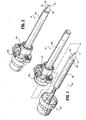
- FIGS. 1 and 2 a trocar assembly constructed in accordance with a preferred embodiment of the present disclosure, and designated generally by reference numeral 10 .
- Trocar assembly 10 is particularly adapted for use in minimally invasive surgical procedures such as endoscopic or laparoscopic procedures.
- trocar assembly 10 includes two principal subassemblies, namely, obturator assembly 100 and cannula assembly 1000 .
- Cannula assembly 1000 may be any cannula assembly suitable for use in a laparoscopic surgical procedure.
- cannula assembly 1000 includes cannula housing 1002 and cannula sleeve 1004 extending from the cannula housing 1002 .
- Either or both cannula housing 1002 and cannula sleeve 1004 may be opaque or transparent in part or in whole and are fabricated from biocompatible metal or polymeric material.
- Cannula assembly 1000 may include an internal seal such as a duck-bill valve or other zero closure valve adapted to close in the absence of a surgical instrument to prevent passage of insufflation gases through the cannula assembly 1000 .
- Trocar assembly 10 may also include a seal assembly 2000 which is preferably releasably mounted to cannula housing 1002 .
- Means for releasably connecting seal assembly 2000 to cannula housing 1002 may include a bayonet coupling, threaded connection, latch, friction fit, tongue and groove arrangements, snap-fit, etc.
- Seal assembly 2000 includes seal housing 2002 and at least one internal seal which is adapted to form a fluid tight seal about an instrument inserted through the seal assembly 2000.
- One suitable seal may be the fabric seal disclosed in commonly assigned U.S. Patent 6,702,787 to Racenet et al ., the entire contents of which are incorporated herein by reference.
- the seal disclosed in the Racenet '787 patent may be a flat septum seal having a first layer of resilient material and a second fabric layer juxtaposed relative to the first layer. Further details of the seal may be ascertained by reference to the '787 patent.
- Seal assembly 2000 may or may not be a component of cannula assembly 1000 .
- the seal assembly may be a separate, removable assembly.
- the seal assembly may comprise an integral part of the cannula assembly 1000 and not be removable.
- obturator assembly 100 includes obturator housing 102 , obturator shaft 104 defining obturator axis "x" and extending distally from the housing 102 and obturator shield 106 coaxially mounted about the obturator shaft 104 .
- obturator shield 106 defines a distal shield nose 206 which may be used to enter, penetrate or pass, etc. through tissue through a blunt or dissection entry.
- obturator shield 106 is permitted to retract in a proximal longitudinal direction to expose the cutting blade disposed at the distal end of the obturator shaft 104 .
- the details of operation and the configuration of shield nose 206 and the cutting blade will be discussed hereinbelow.
- obturator housing 102 includes housing base 108 and housing cover 110 . Once the appropriate components are positioned therewithin (as described below), housing base 108 may be attached to housing cover 110 by engaging mating surfaces, for example, by resilient depending latches 112 of cover 110 interlocking with correspondingly dimensioned latch openings 114 of housing base 108. Preferably, to uniformly connect base 108 and cover 110 , at least three corresponding latches 112 and openings 114 are spaced evenly around the circumference of the cover 110 and the base 108 , respectively. Preferably, obturator housing 102 is configured and dimensioned to functionally cooperate with cannulas that range in size, e.g., from about 5 mm to about 15 mm in diameter.
- obturator housing 102 further includes dial or activator member 116 and control member 118 both of which are housed within the obturator housing 102 .
- Activator member 116 defines activator disk 120 and activator collar 122 extending distally from the activator disk 120 .
- Activator disk 120 defines raised tab 124 which is contoured for manual engagement by the fingers of the operator. Raised tab 124 extends beyond opening 126 of housing cover 110 . Raised tab 124 further includes indicia in the form of recessed arrow 128 which identifies the status or position of activator member 116.
- Activator collar 122 includes axial slot 130 and axial rib 132 ( FIG.
- Activator member 116 is adapted for limited rotational movement as depicted by directional arrow "a" about longitudinal axis "x" between initial and release positions to respectively secure and release obturator shield 106 ( FIG. 4 ).
- the initial position of activator member 116 corresponds to the first mode of operation of obturator assembly 100 where obturator shield 106 is prevented from retracting and the distal shield nose 206 is used to pass through tissue.
- FIG. 6 illustrates the initial position of activator member 116 .
- the release position corresponds to the second mode of operation of obturator assembly 100 where obturator shield 106 is permitted to retract and the cutting blade is used to pierce through tissue.
- control member 118 is fixed within obturator housing 102 .
- Control member 118 includes control disk 134 and limiting collar 136 extending from the proximal side or face of control disk 134 .
- Control disk 134 includes a plurality of alternating tabs 138 and recesses 140 disposed along the outer periphery of the control disk 134 .
- Tabs 138 are received within corresponding internal recesses 140 ( FIG. 6 ) defined in the inner wall of housing cover 110 to secure control member 118 within obturator housing 102 .
- Control member 118 also includes secondary aperture 142 which is radially or laterally spaced from longitudinal axis "x".
- Control disk 134 further includes cylindrical shaft mount 144 and spring mount 146 both of which extend from the distal face of the control disk 134 .
- shaft mount 144 is generally aligned with longitudinal axis "x" and includes bifurcated tabs 148 and central channel 150 .
- Spring mount 146 is laterally or radially spaced from the longitudinal axis "x”.
- limiting collar 136 of control member 118 is dimensioned to receive activator collar 122 of activator member 116 in the assembled condition of the components, and to permit the activator collar 122 to rotate within the limiting collar 136 .
- Limiting collar 136 defines recessed groove 152 which extends about 1 ⁇ 2 the perimeter of the limiting collar 136 .
- Axial rib 132 of activator member 116 traverses recessed groove 152 of control member 118 during rotation of the activator member 116 between the initial and release positions.
- recessed groove 152 defines abutment walls 154, 156 at each end of the recessed groove 152 .
- Abutment walls 154, 156 serve as stop(s) to ensure and/or confirm placement of activator member 116 in the initial or release position. Specifically, abutment walls 154, 156 serve as a tactile indicator that activator member 116 has been moved to either the initial or release position.
- obturator housing 100 further includes indicator collar 158 .
- indicator collar 158 defines internal channel 160 and has distal collar extension 162 .
- Collar extension 162 includes inner tabs 164 on its inner surface.
- Indicator collar 158 further includes transverse arm 166 extending radially outwardly from indicator collar 158 and shield position indicator, such as indicator flag 168 .
- Transverse arm 166 includes axial pin 170 which depends in a proximal direction from the arm 166 .
- Axial pin 170 is in general axial alignment with secondary aperture 142 of control member 118 and traverses the secondary aperture 142 during proximal movement of the indicator collar 158 .
- Indicator flag 168 is visible from the exterior of obturator housing 102 as it extends through groove 172 of housing cover 110 (see FIGS. 3 and 4 ).
- indicator flag 168 is colored to contrast sharply with the surrounding housing components.
- indicator flag 168 may be red if the surrounding housing components are white or light colored.
- indicator collar 158 further includes collar ledge 174 and a pair of posts 176 formed below the ledge 174 and extending radially outwardly from the ledge 174 .
- indicator collar 158 is spring biased in the distal direction by coil spring 178 .
- coil spring 178 is received within internal channel 160 of indicator collar 158 and engages internal shelf 160s of the indicator collar 158 .
- the proximal end of coil spring 178 is coaxially positioned about spring mount 144 depending from the distal face of control member 118 .
- obturator assembly 100 includes a latching mechanism disposed within obturator housing 102 to prevent proximal movement of obturator shield 106 until such time as the obturator assembly 100 is properly mounted to cannula assembly 1000 and the surgeon is prepared to begin trocar entry.
- Latching mechanism includes latch member 180 , and release member such as slider 182 .
- Latch member 180 has two vertical legs 184 connected by web 186 .
- a pair of biasing posts 188 extends outwardly, one for each side of latch member 180 .
- Latch member 180 is preferably molded as part of housing base 108 in cantilever fashion. However, latch member 180 may be formed as a separate element and secured to base 108 by suitable known techniques.
- Slider 182 includes slider post 190 disposed at its lower end, arming button 192 extending distally from the distal face of slider 182 and a pair of slider legs 194 which terminate in crooks 196 .
- Crooks 196 defined in slider legs 194 are configured and dimensioned to engage posts 188 of latch member 180 , as shown in FIGS. 10 and 11 .
- Slider 182 is distally biased by slider spring 198 which is maintained in axial alignment by slider post 190 of slider 182 .
- the proximal end of slider spring 198 bears against the inner surface of control member 118 and is maintained in position between slider post 190 and spring mount 146 of the control member 118 . (See FIGS. 12 and 13 ).
- the distal biasing of slider 182 causes arming button 192 to project through opening 108a formed in housing base 108 .
- the lower end or transverse leg 200 of slider 182 resides with mounting posts 202 of housing base 108 ( FIG. 3 ).
- obturator shield 106 has shield linkage 204 operatively connected thereto and along with the obturator shield 106 defines an outer member of obturator assembly 100 .
- shield linkage 204 is connected to obturator shield 106 through an arrangement including diametrical tabs 208 extending from the distal end of shield linkage 204 , which are received within corresponding openings 210 of obturator shield 106 in snap relation therewith.
- Other means for connecting the components of obturator shield 106 are also envisioned including snap fit arrangements, adhesives, welding tongue and groove arrangements, etc.
- obturator shield 106 and shield linkage 204 are a single component.
- shield linkage 204 extends within housing base 108 and is at least partially received within collar extension 162 .
- Shield linkage 204 includes a pair of diametrically opposed outer grooves 212 which receive inner tabs 164 of collar extension 162 to operatively connect shield extension 204 and indicator collar 158 .
- obturator shield 106 and shield nose 206 are adapted for reciprocal axial movement along axis "x" and relative to obturator housing 102 and obturator shaft 104 concurrently with corresponding movement of the indicator collar 158 .
- shield nos e 206 may be tapered, conical or frusto-conical in configuration, and is adapted to pass through tissue and may be capable of cutting or piercing through tissue.
- shield nose 206 has an irregular shaped with rounded tip 214 .
- shield nose 206 is generally tapered in configuration defining a complex curved arrangement.
- the shield nose 206 in a first profile of shield nose 206 , includes opposed concave surfaces 216 .
- shield nose 206 defines convex surfaces 218 .
- This alternating concave and convex arrangement provides a substantially reduced profile (in cross-section) compared to conventional conically shaped obturators thereby providing an enhanced ability to penetrate or pass through tissue layers.
- Various radii of curvature are contemplated.
- Rounded tip 214 by its arcuate configuration, minimizes the potential of undesired or unintended piercing of tissue. Alternatively, it is envisioned that rounded tip 214 may be more pointed to also pierce tissue if desired.
- This particular configuration of shield nose 206 is disclosed in commonly assigned U.S. Patent Publication No. 2006/0226655, filed October 12, 2006 , the contents of which are incorporated in its entirety by reference herein. Shield nose 206 also defines knife slot 220 .
- Obturator shaft 104 includes obturator rod 222 and blade 224 mounted to the obturator rod 222 .
- Obturator rod 222 defines proximal end 226 which passes through opening 160 of indicator collar 158 and is received within shaft mount 144 of control member 118 .
- Proximal end 226 of obturator rod 222 includes circumferential recess 228 which receives bifurcated tabs 148 of shaft mount 144 of control member 118 in snap relation therewith. In this manner, obturator rod 104 is fixed to obturator housing 102 .
- Knife blade 224 may be secured within knife slot 230 by reception of locking projection 232 within knife aperture 234 .
- Conventional means including adhesives, cements, etc. are also envisioned.
- Knife blade 224 is preferably a flat or thin blade and fabricated from stainless steel by a suitable process, e.g., by stamping or metal injection molding and includes opposed cutting edges 236 which extend to penetrating tip 238 . Knife blade 224 is accommodated within knife slot 220 of shield nose 206.
- Obturator assembly 100 has two modes of operation. In the first mode of operation, obturator shield 106 is locked in its distal position and nose shield 206 is applied against the tissue to penetrate or pass through the tissue through a blunt or dissecting entry. In the second mode, nose shield 206 and obturator shield 106 are permitted to retract to expose knife blade 224 to contact and penetrate the tissue. Activator member 116 controls operation of obturator assembly 100 between the two modes.
- obturator assembly 100 is inserted within cannula assembly 1000 and advanced to where obturator housing 102 is approximated with seal housing 2002 of the seal assembly 2000 .
- Seal assembly 2000 may comprise a separate part or may be a component of cannula assembly 1000 .
- Seal housing 2002 and housing base 108 of obturator housing 102 may be appropriately dimensioned to form a friction fit or may be coupled to each other by conventional means including bayonet coupling, tongue-groove, etc.
- arming button 192 of slider 182 engages proximal surface 2004 of seal housing 2002 and is forced upwardly (depicted by directional arrow "u") from the position depicted in FIG.
- slider 182 pivots or angulates whereby legs 194 of the slider 182 push latch member 180 in a radial outward direction (depicted by directional arrow "z") such that web portion 186 of latch member 180 is out of axial alignment with ledge 174 of indicator collar 158 .
- indicator collar 158 , obturator shield 106 and shield nose 206 are free to axially move provided activator member 116 is in the second mode of operation.
- This decision may be predicated on whether or not an initial entry opening has been made within the tissue, and, if so, thereby requiring a bladeless entry into the tissue corresponding to the first mode of operation of obturator assembly 100 . If a bladeless or blunt entry is selected, the surgeon will position activator member 116 in the initial position of FIG. 6 . In this position, activator collar 122 is positioned over axial pin 170 of indicator collar 158 and thus prevents proximal retracting movement of the indicator collar 158 and obturator shield 106 . Visual confirmation of the positioning of activator collar 122 in the initial position is provided by indicator arrow 128 of raised tab 124 .
- the initial position of activator collar 122 corresponds to recessed arrow 128 being arranged in diametrical opposed relation to indicator flag 168 as shown in FIG. 6 .
- the surgeon then applies shield nose 206 to the tissue and exerts a distal force on the assembly 10 .
- Shield nose 206 passes through tissue, e.g., by a blunt dissecting action, to access the underlying surgical site, e.g., the abdominal cavity.
- Obturator assembly 100 may be removed from cannula assembly 1000 and surgery may be performed with instruments introduced within cannula assembly 1000.
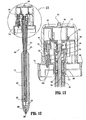
- activator member 116 is selectively moved from the initial position of FIG. 6 to the release position of FIG. 16 by rotating the activator member 116 about longitudinal axis "x" such that recessed arrow 128 of the activator member 116 is aligned with indicator flag 168 thereby providing visual confirmation of the positioning of activator member 116 .
- Engagement of axial rib 122 of activator member 116 with wall 156 ( FIG. 3 ) of control member 118 also provides tactile confirmation of the positioning of activator member 116 in the release position.
- axial slot 130 of activator collar 122 is in general alignment with axial pin 170 of indicator collar 158 .
- the surgeon begins to insert trocar assembly 10 through the body wall of the patient.
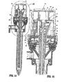
- Shield nose 206 contacts the tissue "t” and is driven upwardly to cause the shield nose 206 , obturator shield 106 , and indicator collar 158 to move proximally (depicted by directional arrow "v") against the bias of coil spring 178.
- obturator assembly 100 must be properly mated with seal assembly 2000 such that the latching mechanism is activated to permit retraction of obturator shield 106 .
- axial pin 170 of the indicator collar 158 traverses secondary aperture 142 of control member 118 and traverses axial slot 130 of activator member 116 . ( FIG. 19 ) Such movement exposes obturator blade 224 to incise the tissue. This armed condition of obturator assembly 100 is visually verified by the proximal location of indicator flag 168 of indicator collar 158 .
- proximal movement of indicator collar 158 causes posts 176 of the indicator collar 158 to ride along outer surfaces 194a of legs 194 of slider 182 to thereby move the slider 182 at least radially inwardly and upwardly (as shown by the directional arrows "r” and “v", respectively) in a general aligned position relative to the obturator axis "x" and disengaged from latch member 180 . (i.e., crooks 196 of slider legs 194 disengage posts 188 of latch member 180). With obturator blade 224 exposed, the surgeon may apply a distally-directed force to obturator assembly 100 to cause penetration through the tissue.
- indicator collar 158 , obturator shield 106 and the shield nose 206 move distally under the influence of coil spring 178 whereby the shield nose 206 covers blade 224 as shown in FIG. 14 .
- the obturator assembly 100 may be removed from cannula assembly 1000 and surgery is performed with instruments inserted through cannula assembly 1000 . It is noted that upon removal of obturator assembly 100 , ledge 174 of indicator collar 158 moves into engagement with web portion 186 of latch member 180 . Concurrently with this movement, slider 182 , which is aligned relative to axis "x" as discussed hereinabove, is driven distally under the influence of coil spring 198 .
- collar ledge 174 of indicator collar 158 securely engages web 186 of latch member 180 to secure shield nose 206 in its extended position. This feature ensures that the removed obturator assembly 100 will not be armed.
- the materials utilized in the components of the presently disclosed trocar assembly generally include materials such as, for example, ABS, polycarbonate, stainless steel, titanium and any other suitable biocompatible metals and/or polymeric materials.
- ABS material is CYCOLAC which is available from General Electric.
- a preferred polycarbonate material is also available from General Electric under the trademark LEXAN.
- An alternative polycarbonate material which may be utilized is CALIBRE polycarbonate available from Dow Chemical Company. The polycarbonate materials may be partially glass filled for added strength.
- FIG. 20 is a perspective view of a penetrating member of the obturator member, in accordance with an example embodiment of the present invention. As depicted in FIG.
- penetrating member 1120 includes, from distal to proximal, cylindrical element 1130 and planar dissecting element 1132 extending contiguously from the cylindrical element 1130 .
- Cylindrical element 1130 defines an arcuate or rounded leading surface 1134 which is atraumatic to tissue and extends a predetermined distance "m" beyond planar dissecting element 1132 . This consequent narrow profile provided by cylindrical element 1130 permits initial insertion within tissue and facilitates, e.g., dissection or advancement, within the tissue without an incising action.
- Cylindrical element 1130 may extend through planar dissecting element 1132 to the obturator rod.
- Planar dissecting element 1132 defines a triangular arrangement having oblique side surfaces 1136 leading to parallel end surfaces 1138 . Side surfaces 1136 may be arcuate or rounded as shown to be atraumatic to tissue. End surfaces 1138 may be blunt.
- shield nose 1144 is positioned about penetrating member 1120 of the obturator member.
- Shield nose 1144 defines a central slot 1146 for reception of penetrating member 1120.
- Shield nose 1144 further defines a central aperture 1148 communicating with central slot 1146 to permit passage of cylindrical element 1130 of penetrating member 1120 .
- Shield nose 1144 moves relative to penetrating member 1120 during longitudinal movement of protective shield 1106 .
- shield nose 1144 is positioned relative to penetrating member 1120 whereby cylindrical portion 1130 of the penetrating member 1120 at least partially extends beyond the shield nose 1144 .
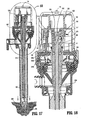
- FIG. 22 illustrates the armed condition of penetrating member 1120 . In this position, penetrating member 1120 is used, by the surgeon applying a distally-directed force to obturator assembly 100 , to penetrate, dissect or pierce through the tissue.
- Other features of this embodiment e.g., those that are proximal of shield nose 1144, may be similar to features described hereinabove.
- Obturator assembly 100 has two modes of operation. In the first mode of operation, obturator shield 106 is locked in its distal position and shield nose 1144 is applied against the tissue to penetrate or pass through the tissue through a blunt or dissecting entry. In the second mode, shield nose 1144 and obturator shield 106 are permitted to retract to expose portions of the penetrating member 1120, e.g., side surfaces 1136, to contact and penetrate the tissue in a different type of dissecting fashion. Activator member 116 controls operation of obturator assembly 100 between the two modes.
- obturator assembly 100 is inserted within cannula assembly 1000 and advanced to where obturator housing 102 is approximated with seal housing 2002 of the seal assembly 2000 .
- Seal assembly 2000 may comprise a separate part or may be a component of cannula assembly 1000 .
- Seal housing 2002 and housing base 108 of obturator housing 102 may be appropriately dimensioned to form a friction fit or may be coupled to each other by conventional means including bayonet coupling, tongue-groove, etc.
- arming button 192 of slider 182 engages proximal surface 2004 of seal housing 2002 and is forced upwardly (depicted by directional arrow "u") from the position depicted in FIG.
- slider 182 pivots or angulates whereby legs 194 of the slider 182 push latch member 180 in a radial outward direction (depicted by directional arrow "z") such that web portion 186 of latch member 180 is out of axial alignment with ledge 174 of indicator collar 158 .
- indicator collar 158 , obturator shield 106 and shield nose 1144 are free to axially move provided activator member 116 is in the second mode of operation.
- This decision may be predicated on whether or not an initial entry opening has been made within the tissue, and, if so, thereby requiring a specific type of bladeless entry into the tissue corresponding to the first mode of operation of obturator assembly 100 . If a first type of bladeless or blunt entry is selected, the surgeon will position activator member 116 in the initial position of FIG. 6 . In this position, activator collar 122 is positioned over axial pin 170 of indicator collar 158 and thus prevents proximal retracting movement of the indicator collar 158 and obturator shield 106 . Visual confirmation of the positioning of activator collar 122 in the initial position is provided by indicator arrow 128 of raised tab 124 .
- the initial position of activator collar 122 corresponds to recessed arrow 128 being arranged in diametrical opposed relation to indicator flag 168 as shown in FIG. 6 .
- the surgeon then applies shield nose 1144 to the tissue and exerts a distal force on the assembly 10 .
- Shield nose 1144 passes through tissue, e.g., by a blunt dissecting action, to access the underlying surgical site, e.g., the abdominal cavity.
- Obturator assembly 100 may be removed from cannula assembly 1000 and surgery may be performed with instruments introduced within cannula assembly 1000 .
- activator member 116 is selectively moved from the initial position of FIG. 6 to the release position of FIG. 16 by rotating the activator member 116 about longitudinal axis "x" such that recessed arrow 128 of the activator member 116 is aligned with indicator flag 168 thereby providing visual confirmation of the positioning of activator member 116 .
- Engagement of axial rib 122 of activator member 116 with wall 156 ( FIG. 3 ) of control member 118 also provides tactile confirmation of the positioning of activator member 116 in the release position.
- axial slot 130 of activator collar 122 is in general alignment with axial pin 170 of indicator collar 158 .
- obturator assembly 100 may be properly mated with seal assembly 2000 such that the latching mechanism is activated to permit retraction of obturator shield 106 .
- axial pin 170 of the indicator collar 158 traverses secondary aperture 142 of control member 118 and traverses axial slot 130 of activator member 116 .
- proximal movement of indicator collar 158 causes posts 176 of the indicator collar 158 to ride along outer surfaces 194a of legs 194 of slider 182 to thereby move the slider 182 at least radially inwardly and upwardly (as shown by the directional arrows "r” and “v", respectively) in a general aligned position relative to the obturator axis "x" and disengaged from latch member 180 (i.e., crooks 196 of slider legs 194 disengage posts 188 of latch member 180 ).
- the surgeon may apply a distally-directed force to obturator assembly 100 to cause penetration through the tissue.
- indicator collar 158 , obturator shield 106 and the shield nose 1144 move distally under the influence of coil spring 178 whereby the shield nose 1144 moves relative to the, e.g., side surfaces 1136 , to the position shown in FIG.21 .
- the obturator assembly 100 may be removed from cannula assembly 1000 and surgery is performed with instruments inserted through cannula assembly 1000 . It is noted that upon removal of obturator assembly 100 , ledge 174 of indicator collar 158 moves into engagement with web portion 186 of latch member 180 ..
- slider 182 Concurrently with this movement, slider 182 , which is aligned relative to axis "x" as discussed hereinabove, is driven distally under the influence of coil spring 198 .
- collar ledge 174 of indicator collar 158 securely engages web 186 of latch member 180 to secure shield nose 1144 in its extended position. This feature ensures that the removed obturator assembly 100 will not be armed.
- An obturator assembly for penetrating tissue and being at least partially positionable within a cannula assembly includes an obturator housing, an obturator shaft connected to the obturator housing and defining a longitudinal axis, a bladeless penetrating member adjacent the distal end of the obturator shaft and an obturator shield mounted about the obturator shaft and having a distal shield nose.
- the obturator shield is adapted for longitudinal movement between an extended position where the bladeless where the bladeless penetration member is substantially enclosed within the shield nose and a retracted position where the bladeless penetrating member is at least partially exposed from the shield nose.
- a manually manipulative member is mounted to the obturator housing and is adapted for rotational movement about the longitudinal axis and relative to the obturator housing between an initial position corresponding to a first mode of operation where the obturator shield is secured in the extended position and the shield nose is used to penetrate tissue, and a release position corresponding to a second mode of operation operatively releasing the obturator shield to permit the obturator shield to move to the retracted position thereof to expose the bladeless penetrating member for further dissecting the tissue.
Landscapes
- Health & Medical Sciences (AREA)
- Life Sciences & Earth Sciences (AREA)
- Surgery (AREA)
- Heart & Thoracic Surgery (AREA)
- Engineering & Computer Science (AREA)
- Biomedical Technology (AREA)
- Nuclear Medicine, Radiotherapy & Molecular Imaging (AREA)
- Medical Informatics (AREA)
- Molecular Biology (AREA)
- Animal Behavior & Ethology (AREA)
- General Health & Medical Sciences (AREA)
- Public Health (AREA)
- Veterinary Medicine (AREA)
- Pathology (AREA)
- Surgical Instruments (AREA)
Applications Claiming Priority (1)
| Application Number | Priority Date | Filing Date | Title |
|---|---|---|---|
| US99777407P | 2007-10-05 | 2007-10-05 |
Publications (2)
| Publication Number | Publication Date |
|---|---|
| EP2044899A2 true EP2044899A2 (de) | 2009-04-08 |
| EP2044899A3 EP2044899A3 (de) | 2010-04-21 |
Family
ID=40328983
Family Applications (1)
| Application Number | Title | Priority Date | Filing Date |
|---|---|---|---|
| EP20080253235 Withdrawn EP2044899A3 (de) | 2007-10-05 | 2008-10-03 | Trokaranordnung ohne Klinge mit zwei Modi |
Country Status (5)
| Country | Link |
|---|---|
| US (2) | US8002788B2 (de) |
| EP (1) | EP2044899A3 (de) |
| JP (1) | JP5393095B2 (de) |
| AU (1) | AU2008229774B2 (de) |
| CA (1) | CA2640394A1 (de) |
Cited By (5)
| Publication number | Priority date | Publication date | Assignee | Title |
|---|---|---|---|---|
| EP2430992A1 (de) * | 2010-09-21 | 2012-03-21 | Tyco Healthcare Group LP | Klingenloser Obturator und klingenlose Obturatorelemente |
| US8845670B2 (en) | 2006-12-15 | 2014-09-30 | Covidien Lp | Trocar assembly with obturator design |
| CN105935307A (zh) * | 2016-06-27 | 2016-09-14 | 江苏风和医疗器材有限公司 | 穿刺芯尖端及具有其的穿刺芯和穿刺器 |
| CN105935309A (zh) * | 2016-06-27 | 2016-09-14 | 江苏风和医疗器材有限公司 | 穿刺芯尖端及具有其的穿刺芯和穿刺器 |
| KR20190000062A (ko) * | 2017-06-22 | 2019-01-02 | (주) 써지코어 | 의료용 트로카 |
Families Citing this family (19)
| Publication number | Priority date | Publication date | Assignee | Title |
|---|---|---|---|---|
| USD606193S1 (en) * | 2008-08-29 | 2009-12-15 | Karl Storz Gmbh & Co. Kg | Trocar |
| KR20150063037A (ko) | 2012-09-28 | 2015-06-08 | 코비디엔 엘피 | 광 투관침 가시화 시스템 및 장치 |
| CA2894544A1 (en) | 2012-12-27 | 2014-07-03 | Covidien Lp | Two-shot molded optical obturator |
| US9597105B2 (en) | 2014-04-17 | 2017-03-21 | Covidien Lp | Vibrating surgical instruments for blunt dissection |
| US9603616B2 (en) | 2014-04-17 | 2017-03-28 | Covidien Lp | Vibrating surgical instruments for blunt dissection and methods for use thereof |
| US10064642B2 (en) | 2015-03-04 | 2018-09-04 | Covidien Lp | Surgical instrument for dissecting tissue |
| CN105935308B (zh) * | 2016-06-27 | 2019-02-05 | 江苏风和医疗器材股份有限公司 | 穿刺芯尖端及具有其的穿刺芯和穿刺器 |
| US10368905B2 (en) | 2017-03-07 | 2019-08-06 | Carefusion 2200, Inc. | Trocar assembly with a cleaning element for use during a laparoscopic procedure |
| US10201396B2 (en) | 2017-03-07 | 2019-02-12 | Carefusion 2200, Inc. | Trocar assembly with a cleaning element for use during a laparoscopic procedure |
| US10398296B2 (en) | 2017-03-07 | 2019-09-03 | Carefusion 2200, Inc. | Trocar assembly with a cleaning element for use during a laparoscopic procedure |
| WO2018222767A1 (en) | 2017-05-31 | 2018-12-06 | Carefusion 2200, Inc. | Trocar assembly with a cleanning element for use during a laparoscopic procedure |
| USD887002S1 (en) * | 2018-07-13 | 2020-06-09 | TianJin Uwell Medical Device Manufacturing Co., Ltd | Medical puncture device |
| US11357542B2 (en) | 2019-06-21 | 2022-06-14 | Covidien Lp | Valve assembly and retainer for surgical access assembly |
| US11812991B2 (en) | 2019-10-18 | 2023-11-14 | Covidien Lp | Seal assemblies for surgical access assemblies |
| USD953522S1 (en) * | 2019-11-04 | 2022-05-31 | Cilag Gmbh International | Cannula |
| US11642153B2 (en) | 2020-03-19 | 2023-05-09 | Covidien Lp | Instrument seal for surgical access assembly |
| US11541218B2 (en) | 2020-03-20 | 2023-01-03 | Covidien Lp | Seal assembly for a surgical access assembly and method of manufacturing the same |
| US11446058B2 (en) | 2020-03-27 | 2022-09-20 | Covidien Lp | Fixture device for folding a seal member |
| US11717321B2 (en) | 2020-04-24 | 2023-08-08 | Covidien Lp | Access assembly with retention mechanism |
Citations (3)
| Publication number | Priority date | Publication date | Assignee | Title |
|---|---|---|---|---|
| US6319266B1 (en) | 2000-03-16 | 2001-11-20 | United States Surgical Corporation | Trocar system and method of use |
| US6702787B2 (en) | 1997-05-02 | 2004-03-09 | Tyco Healthcare Group Lp | Trocar seal system |
| US20060226655A1 (en) | 2005-04-12 | 2006-10-12 | Smith Robert C | Optical trocar with scope holding assembly |
Family Cites Families (69)
| Publication number | Priority date | Publication date | Assignee | Title |
|---|---|---|---|---|
| US4535773A (en) * | 1982-03-26 | 1985-08-20 | Inbae Yoon | Safety puncturing instrument and method |
| US4601710B1 (en) * | 1983-08-24 | 1998-05-05 | United States Surgical Corp | Trocar assembly |
| US4654030A (en) * | 1986-02-24 | 1987-03-31 | Endotherapeutics | Trocar |
| US5030206A (en) * | 1986-10-17 | 1991-07-09 | United States Surgical Corporation | Trocar |
| US4902280A (en) * | 1986-10-17 | 1990-02-20 | United States Surgical Corporation | Trocar |
| US4931042A (en) * | 1987-10-26 | 1990-06-05 | Endotherapeutics | Trocar assembly with improved latch |
| US5215526A (en) * | 1988-07-06 | 1993-06-01 | Ethicon, Inc. | Safety trocar |
| GB8816033D0 (en) * | 1988-07-06 | 1988-08-10 | Ethicon Inc | Improved safety trocar |
| US5217441A (en) * | 1989-08-15 | 1993-06-08 | United States Surgical Corporation | Trocar guide tube positioning device |
| US5114407A (en) * | 1990-08-30 | 1992-05-19 | Ethicon, Inc. | Safety mechanism for trocar |
| US5318580A (en) * | 1990-09-11 | 1994-06-07 | Origin Medsystems, Inc. | Retractable trocar |
| AU644900B2 (en) * | 1990-10-05 | 1993-12-23 | United States Surgical Corporation | Safety trocar |
| US5116353B1 (en) * | 1990-10-05 | 1996-09-10 | Digital Voice Systems Inc | Safety trocar |
| US5827315A (en) | 1994-01-04 | 1998-10-27 | Yoon; Inbae | Safety penetrating instrument with penetrating member protected after penetration to predetermined depth |
| US5350393A (en) * | 1992-01-06 | 1994-09-27 | Inbae Yoon | Safety trocar penetrating instrument |
| US5645556A (en) * | 1990-12-18 | 1997-07-08 | Yoon; Inbae | Safety penetrating instrument with triggered penetrating member retraction and single or multiple safety member protrusion |
| US5645557A (en) * | 1990-12-18 | 1997-07-08 | Yoon; Inbae | Safety penetrating instrument with triggered penetrating member retraction and safety member protrusion |
| US5226426A (en) * | 1990-12-18 | 1993-07-13 | Inbae Yoon | Safety penetrating instrument |
| US5431635A (en) * | 1990-12-18 | 1995-07-11 | Yoon; Inbae | Safety penetrating instrument having a triggered safety member for establishing an endoscopic portal in an anatomical cavity wall |
| US5578053A (en) * | 1993-06-24 | 1996-11-26 | Yoon; Inbae | Safety needle instrument having a triggered safety member |
| US5104382A (en) * | 1991-01-15 | 1992-04-14 | Ethicon, Inc. | Trocar |
| US5474539A (en) * | 1991-02-07 | 1995-12-12 | Origin Medsystems, Inc. | Trocar with retracting tip |
| US5152754A (en) * | 1991-02-15 | 1992-10-06 | Minnesota Mining And Manufacturing Company | Trocar |
| US5295993A (en) * | 1991-04-30 | 1994-03-22 | United States Surgical Corporation | Safety trocar |
| US5360405A (en) | 1991-11-27 | 1994-11-01 | Inbae Yoon | Automatic retractable safety penetrating instrument |
| US5645076A (en) | 1991-08-14 | 1997-07-08 | Yoon; Inbae | Automatic retractable safety penetrating instrument |
| US5312354A (en) * | 1991-11-04 | 1994-05-17 | American Cyanamid Company | Safety trocar instrument having a retractable point actuated by a trigger sleeve |
| US5158552A (en) * | 1991-11-04 | 1992-10-27 | American Cyanamid Company | Safety trocar instrument having a retractable trocar actuated by relief of pressure on the trocar point |
| US5441513A (en) * | 1992-03-12 | 1995-08-15 | United States Surgical Corporation | Retracting tip trocar assembly |
| US5248298A (en) * | 1992-04-16 | 1993-09-28 | Ethicon, Inc. | Insert for shielded trocar |
| US5290243A (en) * | 1992-07-16 | 1994-03-01 | Technalytics, Inc. | Trocar system |
| US5246425A (en) * | 1992-09-21 | 1993-09-21 | Daniel Hunsberger | Trocar and cannula assembly |
| US5275583A (en) * | 1992-10-05 | 1994-01-04 | Lawrence Crainich | Trocar assembly with independently acting shield means |
| US5356421A (en) * | 1992-10-07 | 1994-10-18 | United States Surgical Corporation | Safety trocar with locking handles |
| US5314417A (en) | 1992-12-22 | 1994-05-24 | Ethicon, Inc. | Safety trocar |
| US5263937A (en) * | 1993-02-11 | 1993-11-23 | Shipp John I | Trocar with profile to reduce insertion force |
| US5387197A (en) * | 1993-02-25 | 1995-02-07 | Ethicon, Inc. | Trocar safety shield locking mechanism |
| US5462532A (en) * | 1993-03-17 | 1995-10-31 | Origin Medsystems, Inc. | Trocar with safety sensing sleeve |
| US5364372A (en) * | 1993-03-29 | 1994-11-15 | Endoscopic Concepts, Inc. | Trocar and cannula |
| US5868773A (en) | 1993-03-29 | 1999-02-09 | Endoscopic Concepts, Inc. | Shielded trocar with safety locking mechanism |
| US5346459A (en) | 1993-04-14 | 1994-09-13 | Minnesota Mining And Manufacturing Company | Trocar |
| US5417705A (en) * | 1993-05-14 | 1995-05-23 | Habley Medical Technology Corp. | Obturator with rotating, resettable safety shield |
| US5437643A (en) * | 1993-05-17 | 1995-08-01 | Ethicon, Inc. | Safety interposer for surgical instruments |
| EP0705077B1 (de) * | 1993-05-28 | 1998-04-08 | Origin Medsystems, Inc. | Trokar mit zurückziehbarer spitze und fühler |
| US5411515A (en) * | 1993-07-29 | 1995-05-02 | Habley Medical Technology Corporation | Obturator with rotating, self-locking and resettable safety shield |
| US5364365A (en) * | 1993-08-30 | 1994-11-15 | Surgin Surgical Instrumentation, Inc. | Safety device for laparoscopic instruments |
| WO1995007053A1 (en) * | 1993-09-07 | 1995-03-16 | Invamed, Inc. | Safety shielded, reusable trocar |
| US5538509A (en) * | 1994-01-31 | 1996-07-23 | Richard-Allan Medical Industries, Inc. | Trocar assembly |
| US5545150A (en) * | 1994-05-06 | 1996-08-13 | Endoscopic Concepts, Inc. | Trocar |
| CA2149290C (en) | 1994-05-26 | 2006-07-18 | Carl T. Urban | Optical trocar |
| US5522833A (en) * | 1994-08-29 | 1996-06-04 | Ethicon Endo-Surgery, Inc. | Retractable obturator for a trocar |
| CA2168694A1 (en) | 1995-03-20 | 1996-09-21 | Wayne P. Young | Trocar assembly with electrocautery penetrating tip |
| US5634911A (en) * | 1995-05-19 | 1997-06-03 | General Surgical Innovations, Inc. | Screw-type skin seal with inflatable membrane |
| US5807338A (en) | 1995-10-20 | 1998-09-15 | United States Surgical Corporation | Modular trocar system and methods of assembly |
| US5674237A (en) | 1996-03-06 | 1997-10-07 | Ott; Henryk | Safety trocar |
| US5669885A (en) | 1996-05-14 | 1997-09-23 | United States Surgical Corporation | Trocar assembly with spring-loaded mechanism |
| US5984941A (en) | 1997-02-13 | 1999-11-16 | Endoscopic Concepts, Inc. | Trocar |
| US6017356A (en) | 1997-09-19 | 2000-01-25 | Ethicon Endo-Surgery Inc. | Method for using a trocar for penetration and skin incision |
| US5904699A (en) | 1997-09-19 | 1999-05-18 | Ethicon Endo-Surgery, Inc. | Trocar for penetration and skin incision |
| US6036711A (en) | 1998-02-18 | 2000-03-14 | United States Surgical Corporation | Reusable cannula |
| EP1161190B1 (de) * | 1999-03-16 | 2006-12-06 | United States Surgical Corporation | Trokarsystem |
| US20020161387A1 (en) | 2000-06-22 | 2002-10-31 | Blanco Ernesto E. | Safety trocar with progressive cutting tip guards and gas jet tissue deflector |
| ES2334841T3 (es) | 2000-08-08 | 2010-03-16 | Tyco Healthcare Group Lp | Pestillo de trocar moldeado. |
| EP2428171B1 (de) * | 2001-09-24 | 2014-02-19 | Applied Medical Resources Corporation | Obturator ohne Klinge |
| JP3928929B2 (ja) * | 2002-01-24 | 2007-06-13 | 株式会社トップ | トロカール |
| EP2545863B1 (de) * | 2003-10-03 | 2020-06-17 | Applied Medical Resources Corporation | Optischer Obturator ohne Klinge |
| CA2542362C (en) * | 2003-10-17 | 2012-12-04 | Tyco Healthcare Group Lp | Expandible surgical access device |
| US7419496B2 (en) * | 2004-08-03 | 2008-09-02 | Staudner Rupert A | Trocar with retractable cutting surface |
| EP1875874B1 (de) | 2006-07-06 | 2013-02-27 | Covidien LP | Trokaranordnung mit zwei Modi |
-
2008
- 2008-10-02 US US12/244,150 patent/US8002788B2/en not_active Expired - Fee Related
- 2008-10-02 AU AU2008229774A patent/AU2008229774B2/en not_active Ceased
- 2008-10-03 EP EP20080253235 patent/EP2044899A3/de not_active Withdrawn
- 2008-10-03 JP JP2008259113A patent/JP5393095B2/ja not_active Expired - Fee Related
- 2008-10-03 CA CA002640394A patent/CA2640394A1/en not_active Abandoned
-
2011
- 2011-07-14 US US13/182,682 patent/US8211135B2/en not_active Expired - Fee Related
Patent Citations (3)
| Publication number | Priority date | Publication date | Assignee | Title |
|---|---|---|---|---|
| US6702787B2 (en) | 1997-05-02 | 2004-03-09 | Tyco Healthcare Group Lp | Trocar seal system |
| US6319266B1 (en) | 2000-03-16 | 2001-11-20 | United States Surgical Corporation | Trocar system and method of use |
| US20060226655A1 (en) | 2005-04-12 | 2006-10-12 | Smith Robert C | Optical trocar with scope holding assembly |
Cited By (9)
| Publication number | Priority date | Publication date | Assignee | Title |
|---|---|---|---|---|
| US8845670B2 (en) | 2006-12-15 | 2014-09-30 | Covidien Lp | Trocar assembly with obturator design |
| EP2430992A1 (de) * | 2010-09-21 | 2012-03-21 | Tyco Healthcare Group LP | Klingenloser Obturator und klingenlose Obturatorelemente |
| AU2011218604B2 (en) * | 2010-09-21 | 2015-02-05 | Covidien Lp | Bladeless obturators and bladeless obturator members |
| US8961552B2 (en) | 2010-09-21 | 2015-02-24 | Covidien Lp | Bladeless obturators and bladeless obturator members |
| US10092321B2 (en) | 2010-09-21 | 2018-10-09 | Covidien Lp | Bladeless obturators and bladeless obturator members |
| CN105935307A (zh) * | 2016-06-27 | 2016-09-14 | 江苏风和医疗器材有限公司 | 穿刺芯尖端及具有其的穿刺芯和穿刺器 |
| CN105935309A (zh) * | 2016-06-27 | 2016-09-14 | 江苏风和医疗器材有限公司 | 穿刺芯尖端及具有其的穿刺芯和穿刺器 |
| CN105935307B (zh) * | 2016-06-27 | 2021-08-06 | 江苏风和医疗器材股份有限公司 | 穿刺芯尖端及具有其的穿刺芯和穿刺器 |
| KR20190000062A (ko) * | 2017-06-22 | 2019-01-02 | (주) 써지코어 | 의료용 트로카 |
Also Published As
| Publication number | Publication date |
|---|---|
| AU2008229774B2 (en) | 2013-05-16 |
| JP2009119248A (ja) | 2009-06-04 |
| US20090093835A1 (en) | 2009-04-09 |
| US8211135B2 (en) | 2012-07-03 |
| EP2044899A3 (de) | 2010-04-21 |
| JP5393095B2 (ja) | 2014-01-22 |
| CA2640394A1 (en) | 2009-04-05 |
| US20110270193A1 (en) | 2011-11-03 |
| US8002788B2 (en) | 2011-08-23 |
| AU2008229774A1 (en) | 2009-04-23 |
Similar Documents
| Publication | Publication Date | Title |
|---|---|---|
| US8002788B2 (en) | Two-mode bladeless trocar assembly | |
| US9113953B2 (en) | Two-mode trocar assembly | |
| EP2142115B1 (de) | Trokaranordnung mit obturator-dissektor | |
| EP1738699B1 (de) | Trokaranordnung mit einem drehbaren Obturatorgehäuse | |
| EP2129413B1 (de) | Trokaranordnung mit obturator und einziehbarem mandrin | |
| US20100016878A1 (en) | Trocar assembly with obturator and retractable stylet | |
| AU2013201687B2 (en) | Trocar assembly with obturator dissector |
Legal Events
| Date | Code | Title | Description |
|---|---|---|---|
| PUAI | Public reference made under article 153(3) epc to a published international application that has entered the european phase |
Free format text: ORIGINAL CODE: 0009012 |
|
| AK | Designated contracting states |
Kind code of ref document: A2 Designated state(s): AT BE BG CH CY CZ DE DK EE ES FI FR GB GR HR HU IE IS IT LI LT LU LV MC MT NL NO PL PT RO SE SI SK TR |
|
| AX | Request for extension of the european patent |
Extension state: AL BA MK RS |
|
| PUAL | Search report despatched |
Free format text: ORIGINAL CODE: 0009013 |
|
| AK | Designated contracting states |
Kind code of ref document: A3 Designated state(s): AT BE BG CH CY CZ DE DK EE ES FI FR GB GR HR HU IE IS IT LI LT LU LV MC MT NL NO PL PT RO SE SI SK TR |
|
| AX | Request for extension of the european patent |
Extension state: AL BA MK RS |
|
| 17P | Request for examination filed |
Effective date: 20101018 |
|
| AKX | Designation fees paid |
Designated state(s): AT BE BG CH CY LI |
|
| RBV | Designated contracting states (corrected) |
Designated state(s): AT BE BG CH CY CZ DE DK EE ES FI FR GB GR HR HU IE IS IT LI LT LU LV MC MT NL NO PL PT RO SE SI SK TR |
|
| REG | Reference to a national code |
Ref country code: DE Ref legal event code: 8566 |
|
| RAP1 | Party data changed (applicant data changed or rights of an application transferred) |
Owner name: COVIDIEN LP |
|
| 17Q | First examination report despatched |
Effective date: 20150429 |
|
| STAA | Information on the status of an ep patent application or granted ep patent |
Free format text: STATUS: THE APPLICATION IS DEEMED TO BE WITHDRAWN |
|
| 18D | Application deemed to be withdrawn |
Effective date: 20180501 |