EP2043922B1 - Ausguss zur sicherstellung der entleerung eines flexiblen behälters - Google Patents
Ausguss zur sicherstellung der entleerung eines flexiblen behälters Download PDFInfo
- Publication number
- EP2043922B1 EP2043922B1 EP07799143A EP07799143A EP2043922B1 EP 2043922 B1 EP2043922 B1 EP 2043922B1 EP 07799143 A EP07799143 A EP 07799143A EP 07799143 A EP07799143 A EP 07799143A EP 2043922 B1 EP2043922 B1 EP 2043922B1
- Authority
- EP
- European Patent Office
- Prior art keywords
- spout
- passageway
- flexible container
- evacuation structure
- evacuation
- Prior art date
- Legal status (The legal status is an assumption and is not a legal conclusion. Google has not performed a legal analysis and makes no representation as to the accuracy of the status listed.)
- Not-in-force
Links
- 239000012530 fluid Substances 0.000 claims abstract description 33
- 239000007788 liquid Substances 0.000 abstract description 4
- 238000005429 filling process Methods 0.000 description 7
- 239000000463 material Substances 0.000 description 6
- 238000000034 method Methods 0.000 description 5
- 239000010410 layer Substances 0.000 description 4
- 230000008569 process Effects 0.000 description 4
- QVGXLLKOCUKJST-UHFFFAOYSA-N atomic oxygen Chemical compound [O] QVGXLLKOCUKJST-UHFFFAOYSA-N 0.000 description 3
- 239000001301 oxygen Substances 0.000 description 3
- 229910052760 oxygen Inorganic materials 0.000 description 3
- 230000006870 function Effects 0.000 description 2
- 239000007789 gas Substances 0.000 description 2
- 230000002401 inhibitory effect Effects 0.000 description 2
- 238000004806 packaging method and process Methods 0.000 description 2
- 238000009877 rendering Methods 0.000 description 2
- 241001122767 Theaceae Species 0.000 description 1
- 239000002253 acid Substances 0.000 description 1
- XAGFODPZIPBFFR-UHFFFAOYSA-N aluminium Chemical compound [Al] XAGFODPZIPBFFR-UHFFFAOYSA-N 0.000 description 1
- 229910052782 aluminium Inorganic materials 0.000 description 1
- 230000004888 barrier function Effects 0.000 description 1
- 230000000903 blocking effect Effects 0.000 description 1
- 235000013351 cheese Nutrition 0.000 description 1
- 235000008504 concentrate Nutrition 0.000 description 1
- 239000012141 concentrate Substances 0.000 description 1
- 235000013409 condiments Nutrition 0.000 description 1
- 238000011109 contamination Methods 0.000 description 1
- 235000013365 dairy product Nutrition 0.000 description 1
- 230000009969 flowable effect Effects 0.000 description 1
- 235000015203 fruit juice Nutrition 0.000 description 1
- 235000021056 liquid food Nutrition 0.000 description 1
- 230000007246 mechanism Effects 0.000 description 1
- 229920000642 polymer Polymers 0.000 description 1
- 235000011962 puddings Nutrition 0.000 description 1
- 235000015067 sauces Nutrition 0.000 description 1
- 239000002356 single layer Substances 0.000 description 1
- 235000020357 syrup Nutrition 0.000 description 1
- 239000006188 syrup Substances 0.000 description 1
Images
Classifications
-
- B—PERFORMING OPERATIONS; TRANSPORTING
- B65—CONVEYING; PACKING; STORING; HANDLING THIN OR FILAMENTARY MATERIAL
- B65D—CONTAINERS FOR STORAGE OR TRANSPORT OF ARTICLES OR MATERIALS, e.g. BAGS, BARRELS, BOTTLES, BOXES, CANS, CARTONS, CRATES, DRUMS, JARS, TANKS, HOPPERS, FORWARDING CONTAINERS; ACCESSORIES, CLOSURES, OR FITTINGS THEREFOR; PACKAGING ELEMENTS; PACKAGES
- B65D75/00—Packages comprising articles or materials partially or wholly enclosed in strips, sheets, blanks, tubes or webs of flexible sheet material, e.g. in folded wrappers
- B65D75/52—Details
- B65D75/58—Opening or contents-removing devices added or incorporated during package manufacture
- B65D75/5861—Spouts
- B65D75/5866—Integral spouts
-
- B—PERFORMING OPERATIONS; TRANSPORTING
- B65—CONVEYING; PACKING; STORING; HANDLING THIN OR FILAMENTARY MATERIAL
- B65D—CONTAINERS FOR STORAGE OR TRANSPORT OF ARTICLES OR MATERIALS, e.g. BAGS, BARRELS, BOTTLES, BOXES, CANS, CARTONS, CRATES, DRUMS, JARS, TANKS, HOPPERS, FORWARDING CONTAINERS; ACCESSORIES, CLOSURES, OR FITTINGS THEREFOR; PACKAGING ELEMENTS; PACKAGES
- B65D2231/00—Means for facilitating the complete expelling of the contents
- B65D2231/001—Means for facilitating the complete expelling of the contents the container being a bag
-
- Y—GENERAL TAGGING OF NEW TECHNOLOGICAL DEVELOPMENTS; GENERAL TAGGING OF CROSS-SECTIONAL TECHNOLOGIES SPANNING OVER SEVERAL SECTIONS OF THE IPC; TECHNICAL SUBJECTS COVERED BY FORMER USPC CROSS-REFERENCE ART COLLECTIONS [XRACs] AND DIGESTS
- Y10—TECHNICAL SUBJECTS COVERED BY FORMER USPC
- Y10S—TECHNICAL SUBJECTS COVERED BY FORMER USPC CROSS-REFERENCE ART COLLECTIONS [XRACs] AND DIGESTS
- Y10S383/00—Flexible bags
- Y10S383/906—Dispensing feature
Definitions
- Flexible polymeric containers are well known for storing and dispensing wine, dairy products, enteral feeding solutions, fruit juices, tea and coffee concentrates, puddings, cheese sauces, and many other flowable materials, including those that must be filled aseptically. These generally include low acid materials.
- Flexible polymeric containers typically have walls made of polymeric films with either a monolayer or multiple layer structure. The particular polymers constituting the container film layers vary depending on the type of material to be placed in the container. The film layers may also include an oxygen barrier material layer to prevent contact between such materials and oxygen or other gas sensitive contents.
- the walls of the flexible containers may be metallized, or coated with a metallic layer such as aluminum to prevent incursion of oxygen or other gases. A separate metallized enclosure may also encase the polymeric container.
- the flexible polymeric containers have inlets and/or spouts for filling and dispensing the flexible container contents.
- the flexible containers are also often placed within a box.
- the spout extends through an opening in the box to dispense the contents.
- Such packaging systems are commonly referred to as "bag-in-box.” Bag-in-box packaging systems are often used in restaurants and convenience stores to facilitate service of liquid food products such as syrups, toppings, and condiments.
- the spout is capped to seal the flexible container and protect the contents from contamination.
- the container, spout, cap, and contents may be heat sterilized using steam, an autoclave process, or similar method.
- the flexible container To access and dispense the contents of the flexible container, the flexible container must be evacuated, generally using a vacuum or suction process. Initially all of the air within the flexible container is evacuated. Subsequently, the fluid in the bag is evacuated.
- Prior art devices have attached various mechanisms directly to the spout in an attempt to solve the above-described problem.
- Several issues have been encountered with these kind of devices. For example, during the filling process of the flexible containers, which is typically done in a high speed and high pressure process, the prior art devices are susceptible of being dislodged from the spout rendering the device inoperative. Moreover, the prior art devices can impede the flow of liquid during the filling process thereby slowing down the filling process
- US 4 998 990 discloses a spoute with an evacuation structure upon which the preamble of claim 1 is based.
- the present invention provides a spout in fluid communication with the flexible container, according to claim 1.
- the present invention provides a more efficient way of evacuating fluid from the flexible container.
- the evacuation structure ensures that the walls of the flexible container will not block the spout and inhibit the fluid evacuation.
- the evacuation structure comprises at least one crosshair.
- the crosshair has two ends, and at least one end of at least one crosshair is pivotally or flexibly connected to the spout.
- the flexible connection allows fluid entering the container to pivot or flex the evacuation structure away from the spout so that the evacuation structure docs not inhibit the filling of the flexible container. The fluid entering the container will physically flex the evacuation structure away from the spout.
- None of the prior art devices described above provided an evacuation structure that pivots or flexes away from the spout during the filling process to allow for an unobstructed passageway for the fluid entering the container.
- the prior art devices all stay in the same position over the bottom end of the passageway throughout the entire filling process. None of the prior art devices pivots or flexes away from the spout during filling.
- the evacuation structure of the present invention will also pivot or flex back towards the spout after filling.
- the evacuation structure can pivot back to the spout in a number of ways.
- One way is for the pivotal connection to have enough structural memory so that during the time after filling and before the flexible container is evacuated, the pivotal connection will return to its original position. Because the flexible containers are generally not evacuated for days and sometimes weeks after filling, the pivotal connection will have enough time to slowly return the evacuation structure to its original position.
- Another way for the evacuation structure to pivot back into place to ensure that the container walls do not block the spout is for the structure to be pivoted back to the spout by the exiting liquid.
- the fluid in the container moves towards the spout
- the flow of the fluid towards the spout, as well as the vacuum being exerted at the spout will pivot the evacuation structure towards the spout.
- the evacuation structure will be in place to prevent the walls of the flexible container from entering the spout during evacuation.
- evacuation structure can be returned to or near the spout by a combination of the structural memory of the pivotal connection and the force exerted by the exiting fluid and vacuum.
- the evacuation structure does not have to be returned to its original position to ensure that the walls of the flexible container do not block the spout and inhibit the fluid evacuation. Rather, the evacuation structure can be adjacent to the spout during evacuation and still perform this function.
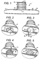
- FIG. 1 shows a spout 10 in fluid communication with a flexible container 12 of the present invention.
- the spout 10 comprises a base 14, a passageway 18, and an evacuation structure 26.
- the base 14 is connected to one of a plurality of walls 16 of the flexible container 12.
- the spout 10 is generally centrally disposed on the base 14, the spout 10 extending in a perpendicular direction from the base 14.
- the passageway 18 within the spout 10 allows for fluid communication with the inside of the flexible container 20.
- the passageway 18 has a top end 22 and a bottom end 24.
- the passageway 18 is substantially perpendicular to the base 14.
- the evacuation structure 26 is connected to the bottom end 24 of the passageway 18 by a pivotal or flexible connection 30.
- the evacuation structure 26 as shown in FIG. 2 is substantially parallel to the base 14 of the spout 10.
- the flexible container 12 is filled with fluid through the spout 10.
- the pivotal connection 30 of the evacuation structure 26 allows it to flex away from the spout 10 when the flexible container 12 is filled with fluid. This is shown by the direction of arrow A in FIG. 3 .
- the pivoting of the evacuation structure 26 ensures the evacuation structure 26 will not obstruct the flow of the fluid, inhibiting the filling of the flexible container 12.
- the evacuation structure 26 is flexibly movable, it will not break off under the force of the fluid during filling.
- the evacuation structure 26 will pivot back towards the spout 10, ensuring that the walls 16 of the flexible container 12 will not inhibit the fluid from evacuating.
- the flow of the evacuating fluid will cause the evacuation structure 26 to return to its original position or close enough to the spout 10 so the evacuation structure 26 will prohibit the walls 16 of the flexible container 12 from blocking the spout 10 during evacuation.
- the pivotal connection 30 will have memory. After filling and before evacuation of the flexible container 12, the memory of the pivotal connection 30 will cause the evacuation structure 26 to pivot back towards the spout 10.
- the evacuation structure 26 will prohibit the walls 16 of the flexible container 12 from entering the passageway 18 when the flexible container 12 is evacuated.
- the evacuation structure 26 ensures that the fluid is not blocked from entering the spout 10 during evacuation by the walls 16 of the flexible container 12.
- the evacuation structure 26 comprises at least one crosshair 28. At least one end of one crosshair 28 is pivotally connected 30 to the bottom end 24 of the passageway 18.
- the evacuation structure 26 comprises at least two crosshairs 28.
- the crosshairs 28 overlapping one another so that both can be pivoted away from the spout 10.
- the crosshairs 28 could have a circular cross-sectional area, a rectangular cross-sectional area, or a variety of other shapes.
- the crosshairs 28 extend across the bottom of the passageway 24 so that each end of the crosshairs 28 is proximate the spout 10.
- the evacuation structure 26 comprises two members 28 which are substantially perpendicular to each other and are connected at the point where they overlap.
- One end of one member 28 is pivotally connected 30 to the bottom end 24 of the passageway 18 of the spout 10.
- the evacuation structure 26 comprises at least two members 28.
- the members 28 are substantially parallel to one another.
- the parallel members 28 can have substantially the same length as one another, or the members 28 can have varying lengths.
- the evacuation structure 26 is a substantially flat permeable plate 32.
- the permeable plate 32 has a periphery 34, and at least one point on the periphery 34 is pivotally connected 30 to the bottom end 24 of the passageway 18 of the spout 10. It should be understood that the permeable plate 32 could have a concave or convex shape to it.
- the present invention provides an evacuation structure 26 that will prohibit the walls 16 of the flexible container 12 from entering the passageway 18 during evacuation, thereby inhibiting the fluid evacuation.
- the present invention also provides an evacuation structure 26 which will not impede the filling of the flexible containers 12.
Landscapes
- Engineering & Computer Science (AREA)
- Mechanical Engineering (AREA)
- Bag Frames (AREA)
- Containers And Packaging Bodies Having A Special Means To Remove Contents (AREA)
- Supply Of Fluid Materials To The Packaging Location (AREA)
Claims (5)
- Stutzen (10), der mit einem flexiblen Behälter (12) in Fluidverbindung ist, wobei der Stutzen (10) folgendes umfasst:eine Basis (14), die mit einer von einer Vielzahl von Wänden (16) des flexiblen Behälters (12) verbunden ist, wobei der Stutzen (10) im Wesentlichen zentral auf der Basis (14) angeordnet ist, und wobei sich der Stutzen (10) in eine zur Basis (14) senkrechten Richtung erstreckt;ein Durchgang (18) in dem Stutzen (10) ermöglicht eine Fluidverbindung mit dem Inneren des flexiblen Behälters (12), wobei der Durchgang (18) ein oberes Ende (22) und ein unteres Ende (24) aufweist, und wobei der Durchgang (18) im Wesentlichen senkrecht zu der Basis (14) ausgerichtet ist; undgekennzeichnet durch eine Entleerungsstruktur (26), die schwenkbar (30) mit dem unteren Ende (24) des Durchgangs (18) verbunden ist und ein Eintreten von Fluid in den Behälter (12) ermöglicht, wobei die Entleerungsstruktur von dem Stutzen (10) weg geschwenkt oder gebogen wird, wenn der flexible Behälter (12) durch den Stutzen (10) mit Fluid befüllt wird, und wobei die Schwenkverbindung (30) ein Gedächtnis aufweist, so dass nach dem Befüllen das Gedächtnis ein Rückschwenken der Entleerungsstruktur (26) hin zum Stutzen (10) bewirkt.
- Stutzen nach Anspruch 1, wobei die Entleerungsstruktur (26) ein Eindringen der Wände (16) des flexiblen Behälters (12) in den Durchgang (18) verhindert, wenn der flexible Behälter (12) entleert wird.
- Stutzen nach Anspruch 1, wobei die Entleerungsstruktur zumindest eine Fadenkreuzstruktur (28) umfasst, bei der zumindest ein Ende eines Fadenkreuzes (28) verschwenkbar (30) mit dem unteren Ende des Durchgangs (18) verbunden ist.
- Stutzen (10) nach Anspruch 1, wobei die Entleerungsstruktur (26) eine im Wesentlichen flache, durchlässige Platte (32) ist, wobei die durchlässige Platte (32) einen Umfang aufweist, und wobei zumindest ein Punkt auf dem Umfang schwenkbar mit dem unteren Ende (24) des Durchgangs (18) verbunden ist.
- Stutzen nach Anspruch 1, wobei die Entleerungsstruktur (26) zumindest zwei Elemente (28) aufweist, die im Wesentlichen parallel zueinander sind.
Priority Applications (1)
| Application Number | Priority Date | Filing Date | Title |
|---|---|---|---|
| EP11007445A EP2407392B1 (de) | 2006-07-07 | 2007-06-28 | Flexibler Behälter mit einem Ausgießer zur Gewährleistung der Entleerung des Behälters |
Applications Claiming Priority (2)
| Application Number | Priority Date | Filing Date | Title |
|---|---|---|---|
| US11/482,622 US7757907B2 (en) | 2006-07-07 | 2006-07-07 | Spout for ensuring evacuation of a flexible container |
| PCT/US2007/072388 WO2008005803A2 (en) | 2006-07-07 | 2007-06-28 | Spout for ensuring evacuation of a flexible container |
Publications (3)
| Publication Number | Publication Date |
|---|---|
| EP2043922A2 EP2043922A2 (de) | 2009-04-08 |
| EP2043922A4 EP2043922A4 (de) | 2010-12-29 |
| EP2043922B1 true EP2043922B1 (de) | 2011-09-28 |
Family
ID=38895342
Family Applications (2)
| Application Number | Title | Priority Date | Filing Date |
|---|---|---|---|
| EP07799143A Not-in-force EP2043922B1 (de) | 2006-07-07 | 2007-06-28 | Ausguss zur sicherstellung der entleerung eines flexiblen behälters |
| EP11007445A Not-in-force EP2407392B1 (de) | 2006-07-07 | 2007-06-28 | Flexibler Behälter mit einem Ausgießer zur Gewährleistung der Entleerung des Behälters |
Family Applications After (1)
| Application Number | Title | Priority Date | Filing Date |
|---|---|---|---|
| EP11007445A Not-in-force EP2407392B1 (de) | 2006-07-07 | 2007-06-28 | Flexibler Behälter mit einem Ausgießer zur Gewährleistung der Entleerung des Behälters |
Country Status (6)
| Country | Link |
|---|---|
| US (2) | US7757907B2 (de) |
| EP (2) | EP2043922B1 (de) |
| AT (1) | ATE526248T1 (de) |
| ES (1) | ES2395115T3 (de) |
| PT (1) | PT2043922E (de) |
| WO (1) | WO2008005803A2 (de) |
Families Citing this family (18)
| Publication number | Priority date | Publication date | Assignee | Title |
|---|---|---|---|---|
| US20100181336A1 (en) * | 2005-08-12 | 2010-07-22 | Carlsberg Breweries A/S | Assembly for dispensing a beverage |
| US7757907B2 (en) * | 2006-07-07 | 2010-07-20 | Ds Smith Plastics Limited | Spout for ensuring evacuation of a flexible container |
| US9174234B2 (en) | 2010-02-18 | 2015-11-03 | Adco Products, Llc | Method of applying a polyurethane adhesive to a substrate |
| US9566594B2 (en) | 2010-02-18 | 2017-02-14 | Adco Products, Llc | Adhesive applicator |
| US9610604B2 (en) | 2010-02-18 | 2017-04-04 | Adco Products, Llc | Multi-bead applicator |
| CA2781214A1 (en) * | 2011-06-28 | 2012-12-28 | Alton Payne | Storage tank |
| US9381536B2 (en) | 2011-12-28 | 2016-07-05 | Adco Products, Llc | Multi-bead applicator |
| WO2013159073A1 (en) | 2012-04-20 | 2013-10-24 | Pedia Solutions, Llc | Apparatus and methods for oral administration of fluids and medical instrumentation |
| AU2013327073A1 (en) | 2012-10-02 | 2015-04-23 | Performance Packaging Of Nevada, Llc | Apparatus for oral delivery of fluids and semi-solid foods |
| USD740430S1 (en) | 2013-04-19 | 2015-10-06 | Pedia Solutions, Llc | Fluid dispensing pacifier |
| US10051990B2 (en) | 2013-11-05 | 2018-08-21 | Plascon Group | Liner for a vessel |
| WO2015068120A1 (en) | 2013-11-05 | 2015-05-14 | Plascon Group | Liner for a vessel |
| US10561272B2 (en) * | 2013-11-05 | 2020-02-18 | Plascon Packaging, Inc. | Selectively sealable liner for a vessel |
| JP6710491B2 (ja) * | 2013-12-26 | 2020-06-17 | 大日本印刷株式会社 | 注出口部材および注出口部材付き袋 |
| US9809370B2 (en) * | 2014-08-14 | 2017-11-07 | Scholle Ipn Corporation | Barrier spout for a flexible bag and a flexible bag having a barrier spout |
| EP4061777A1 (de) | 2019-11-20 | 2022-09-28 | Liqui-Box Corporation | Filteranpassung für flüssigkeitsverpackungen |
| US11459154B2 (en) | 2020-04-08 | 2022-10-04 | Liqui-Box Corp. | System for preventing blockage of evacuation of flexible packaging |
| AU2022325519A1 (en) * | 2021-08-09 | 2024-02-01 | Winpak Ltd. | Multi-aperture spill-resistant spout |
Family Cites Families (11)
| Publication number | Priority date | Publication date | Assignee | Title |
|---|---|---|---|---|
| US1241511A (en) * | 1913-09-05 | 1917-10-02 | Justrite Manufacturing Co | Safety oil-can. |
| US1339008A (en) * | 1920-03-09 | 1920-05-04 | Deborah V Strong | Teapot-strainer |
| US2753051A (en) * | 1952-12-26 | 1956-07-03 | Earl S Tupper | Hinged and swivellable seal and strainer |
| US3674183A (en) * | 1971-02-01 | 1972-07-04 | Herny B Venable | Dispensing device |
| US4998990A (en) * | 1988-12-20 | 1991-03-12 | The Coca-Cola Company | Collapsible bag with evacuation passageway and method for making the same |
| US5409144A (en) * | 1991-12-06 | 1995-04-25 | Liquid Molding Systems Inc. | Dispensing valve for packaging |
| US6230940B1 (en) * | 1999-11-02 | 2001-05-15 | Seaquist Closures Foreign, Inc. | One-Piece dispensing system and method for making same |
| DE60037537T2 (de) * | 1999-11-10 | 2008-12-24 | Scholle Corp., Irvine | Biegsame beutel zur ausgabe von flüssigkeiten und verfahren |
| EP1118550A3 (de) * | 2000-01-19 | 2002-10-23 | Riso Kagaku Corporation | Flüssigkeitsbehälter |
| US7721759B2 (en) * | 2005-09-07 | 2010-05-25 | Chep Technology Pty Limited | Valve having a protective cage |
| US7757907B2 (en) * | 2006-07-07 | 2010-07-20 | Ds Smith Plastics Limited | Spout for ensuring evacuation of a flexible container |
-
2006
- 2006-07-07 US US11/482,622 patent/US7757907B2/en active Active
-
2007
- 2007-06-28 EP EP07799143A patent/EP2043922B1/de not_active Not-in-force
- 2007-06-28 WO PCT/US2007/072388 patent/WO2008005803A2/en not_active Ceased
- 2007-06-28 AT AT07799143T patent/ATE526248T1/de not_active IP Right Cessation
- 2007-06-28 PT PT07799143T patent/PT2043922E/pt unknown
- 2007-06-28 EP EP11007445A patent/EP2407392B1/de not_active Not-in-force
- 2007-06-28 ES ES07799143T patent/ES2395115T3/es active Active
-
2010
- 2010-06-22 US US12/820,285 patent/US8083109B2/en not_active Expired - Fee Related
Also Published As
| Publication number | Publication date |
|---|---|
| EP2043922A4 (de) | 2010-12-29 |
| PT2043922E (pt) | 2011-10-19 |
| US20080006655A1 (en) | 2008-01-10 |
| US20100258589A1 (en) | 2010-10-14 |
| EP2407392B1 (de) | 2012-11-28 |
| ATE526248T1 (de) | 2011-10-15 |
| ES2395115T3 (es) | 2013-02-08 |
| WO2008005803A3 (en) | 2008-08-28 |
| WO2008005803A2 (en) | 2008-01-10 |
| US8083109B2 (en) | 2011-12-27 |
| EP2407392A1 (de) | 2012-01-18 |
| US7757907B2 (en) | 2010-07-20 |
| EP2043922A2 (de) | 2009-04-08 |
Similar Documents
| Publication | Publication Date | Title |
|---|---|---|
| EP2043922B1 (de) | Ausguss zur sicherstellung der entleerung eines flexiblen behälters | |
| US6073807A (en) | Flexible container with evacuation form insert | |
| EP1453737B1 (de) | Flexible kunststoffbehälter | |
| US6715644B2 (en) | Flexible plastic container | |
| EP1663848B1 (de) | Wasserkühleradapter | |
| AU2002359380A1 (en) | Flexible plastic container | |
| UA79486C2 (uk) | Відкривальний пристрій багаторазової дії для упаковок з розливними харчовими продуктами | |
| US11851256B2 (en) | System for preventing blockage of evacuation of flexible packaging | |
| WO2003016163A1 (en) | Container with discharge flow velocity mechanism | |
| US20030155321A1 (en) | Bottle and bottle closure assembly | |
| US20100167892A1 (en) | Collapsible Bag for Dispensing Liquids, Method of Manufacturing, and Method of Use Thereof | |
| US20050211730A1 (en) | Valve for a flexible container | |
| WO2004031041A1 (en) | Patch for flexible container | |
| US20050230420A1 (en) | Flexible plastic container | |
| AU2004212611A1 (en) | Flexible plastic container | |
| HK1072587A (en) | Flexible plastic container |
Legal Events
| Date | Code | Title | Description |
|---|---|---|---|
| PUAI | Public reference made under article 153(3) epc to a published international application that has entered the european phase |
Free format text: ORIGINAL CODE: 0009012 |
|
| 17P | Request for examination filed |
Effective date: 20090205 |
|
| AK | Designated contracting states |
Kind code of ref document: A2 Designated state(s): AT BE BG CH CY CZ DE DK EE ES FI FR GB GR HU IE IS IT LI LT LU LV MC MT NL PL PT RO SE SI SK TR |
|
| AX | Request for extension of the european patent |
Extension state: AL BA HR MK RS |
|
| DAX | Request for extension of the european patent (deleted) | ||
| RAP1 | Party data changed (applicant data changed or rights of an application transferred) |
Owner name: DS SMITH PLASTICS LIMITED Owner name: SMITH, MARK Owner name: PETRIEKIS, DANIEL |
|
| A4 | Supplementary search report drawn up and despatched |
Effective date: 20101125 |
|
| RIC1 | Information provided on ipc code assigned before grant |
Ipc: B67D 3/00 20060101ALI20101119BHEP Ipc: B65D 75/58 20060101ALI20101119BHEP Ipc: B65D 35/00 20060101AFI20080310BHEP |
|
| GRAP | Despatch of communication of intention to grant a patent |
Free format text: ORIGINAL CODE: EPIDOSNIGR1 |
|
| GRAC | Information related to communication of intention to grant a patent modified |
Free format text: ORIGINAL CODE: EPIDOSCIGR1 |
|
| RAP1 | Party data changed (applicant data changed or rights of an application transferred) |
Owner name: DS SMITH PLASTICS LIMITED |
|
| RIC1 | Information provided on ipc code assigned before grant |
Ipc: B65D 75/58 20060101ALI20110317BHEP Ipc: B65D 35/00 20060101AFI20110317BHEP Ipc: B67D 3/00 20060101ALI20110317BHEP |
|
| RIN1 | Information on inventor provided before grant (corrected) |
Inventor name: SMITH, MARK Inventor name: PETRIEKIS, DANIEL |
|
| GRAS | Grant fee paid |
Free format text: ORIGINAL CODE: EPIDOSNIGR3 |
|
| GRAA | (expected) grant |
Free format text: ORIGINAL CODE: 0009210 |
|
| AK | Designated contracting states |
Kind code of ref document: B1 Designated state(s): AT BE BG CH CY CZ DE DK EE ES FI FR GB GR HU IE IS IT LI LT LU LV MC MT NL PL PT RO SE SI SK TR |
|
| REG | Reference to a national code |
Ref country code: GB Ref legal event code: FG4D |
|
| REG | Reference to a national code |
Ref country code: CH Ref legal event code: EP |
|
| REG | Reference to a national code |
Ref country code: PT Ref legal event code: SC4A Free format text: AVAILABILITY OF NATIONAL TRANSLATION Effective date: 20111011 |
|
| REG | Reference to a national code |
Ref country code: IE Ref legal event code: FG4D |
|
| REG | Reference to a national code |
Ref country code: DE Ref legal event code: R096 Ref document number: 602007017556 Country of ref document: DE Effective date: 20111124 |
|
| REG | Reference to a national code |
Ref country code: NL Ref legal event code: T3 |
|
| PG25 | Lapsed in a contracting state [announced via postgrant information from national office to epo] |
Ref country code: LT Free format text: LAPSE BECAUSE OF FAILURE TO SUBMIT A TRANSLATION OF THE DESCRIPTION OR TO PAY THE FEE WITHIN THE PRESCRIBED TIME-LIMIT Effective date: 20110928 Ref country code: FI Free format text: LAPSE BECAUSE OF FAILURE TO SUBMIT A TRANSLATION OF THE DESCRIPTION OR TO PAY THE FEE WITHIN THE PRESCRIBED TIME-LIMIT Effective date: 20110928 Ref country code: SE Free format text: LAPSE BECAUSE OF FAILURE TO SUBMIT A TRANSLATION OF THE DESCRIPTION OR TO PAY THE FEE WITHIN THE PRESCRIBED TIME-LIMIT Effective date: 20110928 |
|
| LTIE | Lt: invalidation of european patent or patent extension |
Effective date: 20110928 |
|
| PG25 | Lapsed in a contracting state [announced via postgrant information from national office to epo] |
Ref country code: LV Free format text: LAPSE BECAUSE OF FAILURE TO SUBMIT A TRANSLATION OF THE DESCRIPTION OR TO PAY THE FEE WITHIN THE PRESCRIBED TIME-LIMIT Effective date: 20110928 Ref country code: AT Free format text: LAPSE BECAUSE OF FAILURE TO SUBMIT A TRANSLATION OF THE DESCRIPTION OR TO PAY THE FEE WITHIN THE PRESCRIBED TIME-LIMIT Effective date: 20110928 Ref country code: GR Free format text: LAPSE BECAUSE OF FAILURE TO SUBMIT A TRANSLATION OF THE DESCRIPTION OR TO PAY THE FEE WITHIN THE PRESCRIBED TIME-LIMIT Effective date: 20111229 Ref country code: CY Free format text: LAPSE BECAUSE OF FAILURE TO SUBMIT A TRANSLATION OF THE DESCRIPTION OR TO PAY THE FEE WITHIN THE PRESCRIBED TIME-LIMIT Effective date: 20110928 Ref country code: SI Free format text: LAPSE BECAUSE OF FAILURE TO SUBMIT A TRANSLATION OF THE DESCRIPTION OR TO PAY THE FEE WITHIN THE PRESCRIBED TIME-LIMIT Effective date: 20110928 |
|
| REG | Reference to a national code |
Ref country code: AT Ref legal event code: MK05 Ref document number: 526248 Country of ref document: AT Kind code of ref document: T Effective date: 20110928 |
|
| PG25 | Lapsed in a contracting state [announced via postgrant information from national office to epo] |
Ref country code: BE Free format text: LAPSE BECAUSE OF FAILURE TO SUBMIT A TRANSLATION OF THE DESCRIPTION OR TO PAY THE FEE WITHIN THE PRESCRIBED TIME-LIMIT Effective date: 20110928 |
|
| PG25 | Lapsed in a contracting state [announced via postgrant information from national office to epo] |
Ref country code: CZ Free format text: LAPSE BECAUSE OF FAILURE TO SUBMIT A TRANSLATION OF THE DESCRIPTION OR TO PAY THE FEE WITHIN THE PRESCRIBED TIME-LIMIT Effective date: 20110928 Ref country code: SK Free format text: LAPSE BECAUSE OF FAILURE TO SUBMIT A TRANSLATION OF THE DESCRIPTION OR TO PAY THE FEE WITHIN THE PRESCRIBED TIME-LIMIT Effective date: 20110928 Ref country code: IS Free format text: LAPSE BECAUSE OF FAILURE TO SUBMIT A TRANSLATION OF THE DESCRIPTION OR TO PAY THE FEE WITHIN THE PRESCRIBED TIME-LIMIT Effective date: 20120128 |
|
| PG25 | Lapsed in a contracting state [announced via postgrant information from national office to epo] |
Ref country code: RO Free format text: LAPSE BECAUSE OF FAILURE TO SUBMIT A TRANSLATION OF THE DESCRIPTION OR TO PAY THE FEE WITHIN THE PRESCRIBED TIME-LIMIT Effective date: 20110928 Ref country code: EE Free format text: LAPSE BECAUSE OF FAILURE TO SUBMIT A TRANSLATION OF THE DESCRIPTION OR TO PAY THE FEE WITHIN THE PRESCRIBED TIME-LIMIT Effective date: 20110928 |
|
| PG25 | Lapsed in a contracting state [announced via postgrant information from national office to epo] |
Ref country code: DK Free format text: LAPSE BECAUSE OF FAILURE TO SUBMIT A TRANSLATION OF THE DESCRIPTION OR TO PAY THE FEE WITHIN THE PRESCRIBED TIME-LIMIT Effective date: 20110928 |
|
| PLBE | No opposition filed within time limit |
Free format text: ORIGINAL CODE: 0009261 |
|
| STAA | Information on the status of an ep patent application or granted ep patent |
Free format text: STATUS: NO OPPOSITION FILED WITHIN TIME LIMIT |
|
| PG25 | Lapsed in a contracting state [announced via postgrant information from national office to epo] |
Ref country code: PL Free format text: LAPSE BECAUSE OF FAILURE TO SUBMIT A TRANSLATION OF THE DESCRIPTION OR TO PAY THE FEE WITHIN THE PRESCRIBED TIME-LIMIT Effective date: 20110928 |
|
| 26N | No opposition filed |
Effective date: 20120629 |
|
| REG | Reference to a national code |
Ref country code: DE Ref legal event code: R097 Ref document number: 602007017556 Country of ref document: DE Effective date: 20120629 |
|
| PG25 | Lapsed in a contracting state [announced via postgrant information from national office to epo] |
Ref country code: MC Free format text: LAPSE BECAUSE OF NON-PAYMENT OF DUE FEES Effective date: 20120630 |
|
| REG | Reference to a national code |
Ref country code: CH Ref legal event code: PL |
|
| REG | Reference to a national code |
Ref country code: ES Ref legal event code: FG2A Ref document number: 2395115 Country of ref document: ES Kind code of ref document: T3 Effective date: 20130208 |
|
| REG | Reference to a national code |
Ref country code: CH Ref legal event code: PL |
|
| REG | Reference to a national code |
Ref country code: IE Ref legal event code: MM4A |
|
| REG | Reference to a national code |
Ref country code: PT Ref legal event code: MM4A Free format text: LAPSE DUE TO NON-PAYMENT OF FEES Effective date: 20130328 |
|
| PG25 | Lapsed in a contracting state [announced via postgrant information from national office to epo] |
Ref country code: LI Free format text: LAPSE BECAUSE OF NON-PAYMENT OF DUE FEES Effective date: 20120630 Ref country code: CH Free format text: LAPSE BECAUSE OF NON-PAYMENT OF DUE FEES Effective date: 20120630 Ref country code: IE Free format text: LAPSE BECAUSE OF NON-PAYMENT OF DUE FEES Effective date: 20120628 |
|
| PG25 | Lapsed in a contracting state [announced via postgrant information from national office to epo] |
Ref country code: PT Free format text: LAPSE BECAUSE OF NON-PAYMENT OF DUE FEES Effective date: 20130328 |
|
| PG25 | Lapsed in a contracting state [announced via postgrant information from national office to epo] |
Ref country code: BG Free format text: LAPSE BECAUSE OF FAILURE TO SUBMIT A TRANSLATION OF THE DESCRIPTION OR TO PAY THE FEE WITHIN THE PRESCRIBED TIME-LIMIT Effective date: 20111228 |
|
| PG25 | Lapsed in a contracting state [announced via postgrant information from national office to epo] |
Ref country code: MT Free format text: LAPSE BECAUSE OF FAILURE TO SUBMIT A TRANSLATION OF THE DESCRIPTION OR TO PAY THE FEE WITHIN THE PRESCRIBED TIME-LIMIT Effective date: 20110928 |
|
| PG25 | Lapsed in a contracting state [announced via postgrant information from national office to epo] |
Ref country code: TR Free format text: LAPSE BECAUSE OF FAILURE TO SUBMIT A TRANSLATION OF THE DESCRIPTION OR TO PAY THE FEE WITHIN THE PRESCRIBED TIME-LIMIT Effective date: 20110928 |
|
| PG25 | Lapsed in a contracting state [announced via postgrant information from national office to epo] |
Ref country code: LU Free format text: LAPSE BECAUSE OF NON-PAYMENT OF DUE FEES Effective date: 20120628 |
|
| PG25 | Lapsed in a contracting state [announced via postgrant information from national office to epo] |
Ref country code: HU Free format text: LAPSE BECAUSE OF FAILURE TO SUBMIT A TRANSLATION OF THE DESCRIPTION OR TO PAY THE FEE WITHIN THE PRESCRIBED TIME-LIMIT Effective date: 20070628 |
|
| PGFP | Annual fee paid to national office [announced via postgrant information from national office to epo] |
Ref country code: GB Payment date: 20140625 Year of fee payment: 8 |
|
| PGFP | Annual fee paid to national office [announced via postgrant information from national office to epo] |
Ref country code: DE Payment date: 20140625 Year of fee payment: 8 Ref country code: ES Payment date: 20140513 Year of fee payment: 8 Ref country code: IT Payment date: 20140609 Year of fee payment: 8 |
|
| PGFP | Annual fee paid to national office [announced via postgrant information from national office to epo] |
Ref country code: NL Payment date: 20140610 Year of fee payment: 8 |
|
| PGFP | Annual fee paid to national office [announced via postgrant information from national office to epo] |
Ref country code: FR Payment date: 20140609 Year of fee payment: 8 |
|
| REG | Reference to a national code |
Ref country code: DE Ref legal event code: R119 Ref document number: 602007017556 Country of ref document: DE |
|
| PG25 | Lapsed in a contracting state [announced via postgrant information from national office to epo] |
Ref country code: IT Free format text: LAPSE BECAUSE OF NON-PAYMENT OF DUE FEES Effective date: 20150628 |
|
| GBPC | Gb: european patent ceased through non-payment of renewal fee |
Effective date: 20150628 |
|
| REG | Reference to a national code |
Ref country code: NL Ref legal event code: MM Effective date: 20150701 |
|
| REG | Reference to a national code |
Ref country code: FR Ref legal event code: ST Effective date: 20160229 |
|
| PG25 | Lapsed in a contracting state [announced via postgrant information from national office to epo] |
Ref country code: GB Free format text: LAPSE BECAUSE OF NON-PAYMENT OF DUE FEES Effective date: 20150628 Ref country code: NL Free format text: LAPSE BECAUSE OF NON-PAYMENT OF DUE FEES Effective date: 20150701 Ref country code: DE Free format text: LAPSE BECAUSE OF NON-PAYMENT OF DUE FEES Effective date: 20160101 |
|
| PG25 | Lapsed in a contracting state [announced via postgrant information from national office to epo] |
Ref country code: FR Free format text: LAPSE BECAUSE OF NON-PAYMENT OF DUE FEES Effective date: 20150630 |
|
| PG25 | Lapsed in a contracting state [announced via postgrant information from national office to epo] |
Ref country code: ES Free format text: LAPSE BECAUSE OF NON-PAYMENT OF DUE FEES Effective date: 20150629 |
|
| REG | Reference to a national code |
Ref country code: ES Ref legal event code: FD2A Effective date: 20180626 |