EP2043910B1 - System for transfer of a liquid such as liquefied natural gas from a ship such as a liquefied natural gas carrier and a floating or fixed unit - Google Patents
System for transfer of a liquid such as liquefied natural gas from a ship such as a liquefied natural gas carrier and a floating or fixed unit Download PDFInfo
- Publication number
- EP2043910B1 EP2043910B1 EP20070823577 EP07823577A EP2043910B1 EP 2043910 B1 EP2043910 B1 EP 2043910B1 EP 20070823577 EP20070823577 EP 20070823577 EP 07823577 A EP07823577 A EP 07823577A EP 2043910 B1 EP2043910 B1 EP 2043910B1
- Authority
- EP
- European Patent Office
- Prior art keywords
- articulated arm
- piping
- manifold
- natural gas
- liquefied natural
- Prior art date
- Legal status (The legal status is an assumption and is not a legal conclusion. Google has not performed a legal analysis and makes no representation as to the accuracy of the status listed.)
- Not-in-force
Links
Images

Classifications
-
- B—PERFORMING OPERATIONS; TRANSPORTING
- B63—SHIPS OR OTHER WATERBORNE VESSELS; RELATED EQUIPMENT
- B63B—SHIPS OR OTHER WATERBORNE VESSELS; EQUIPMENT FOR SHIPPING
- B63B27/00—Arrangement of ship-based loading or unloading equipment for cargo or passengers
- B63B27/24—Arrangement of ship-based loading or unloading equipment for cargo or passengers of pipe-lines
-
- B—PERFORMING OPERATIONS; TRANSPORTING
- B67—OPENING, CLOSING OR CLEANING BOTTLES, JARS OR SIMILAR CONTAINERS; LIQUID HANDLING
- B67D—DISPENSING, DELIVERING OR TRANSFERRING LIQUIDS, NOT OTHERWISE PROVIDED FOR
- B67D9/00—Apparatus or devices for transferring liquids when loading or unloading ships
- B67D9/02—Apparatus or devices for transferring liquids when loading or unloading ships using articulated pipes
-
- F—MECHANICAL ENGINEERING; LIGHTING; HEATING; WEAPONS; BLASTING
- F17—STORING OR DISTRIBUTING GASES OR LIQUIDS
- F17D—PIPE-LINE SYSTEMS; PIPE-LINES
- F17D1/00—Pipe-line systems
- F17D1/08—Pipe-line systems for liquids or viscous products
- F17D1/14—Conveying liquids or viscous products by pumping
-
- Y—GENERAL TAGGING OF NEW TECHNOLOGICAL DEVELOPMENTS; GENERAL TAGGING OF CROSS-SECTIONAL TECHNOLOGIES SPANNING OVER SEVERAL SECTIONS OF THE IPC; TECHNICAL SUBJECTS COVERED BY FORMER USPC CROSS-REFERENCE ART COLLECTIONS [XRACs] AND DIGESTS
- Y10—TECHNICAL SUBJECTS COVERED BY FORMER USPC
- Y10T—TECHNICAL SUBJECTS COVERED BY FORMER US CLASSIFICATION
- Y10T137/00—Fluid handling
- Y10T137/8593—Systems
- Y10T137/8807—Articulated or swinging flow conduit
Definitions
- the invention relates to a system for transferring a fluid such as liquefied natural gas between a vessel such as a shuttle methane tanker and a floating or fixed fluid production or storage unit of the articulated arm type with n degrees of freedom, in general 6, each ensured by a rotating joint.
- a system of this type is known from the document US 4408 943 , which is considered to be the closest state of the art.
- the articulated arm must be able to be connected to the LNG carrier and disconnected safely in difficult sea conditions.
- This system and, in general, all fluid transfer systems based rigid pipes articulated to each other, have the disadvantage that all the rotary joints are provided on the articulated arm which, therefore, has a structure complex, bulky, large mass and whose rotations are difficult to control.
- the invention aims to overcome this disadvantage.
- the transfer system according to the invention is characterized in that at least one rotary joint is provided on the ship.
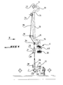
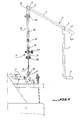
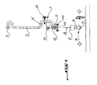
- reference numeral 1 denotes a vessel such as a shuttle tanker, 2 the manifold of the ship, 3 an articulated transfer arm which comprises at its free end a connection / disconnection device to the manifold, designated by the reference 4 and whose other end is connected to the piping 5 of the production or storage unit.
- This unit could be floating or fixed.
- the figure shows the transfer system during a connection to the manifold of the ship.
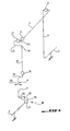
- the articulated arm 3 essentially comprises three segments of pipe articulated to each other, namely a first support segment 6 whose free end is connected to the pipework 5, a second arm segment 7, called the inner arm, which is connected to the segment 6 by a first rotary joint 8 and whose other end is connected by a second rotary joint 9 to a 90 degree elbow 12 connected at its other end to a third rotary joint 11 which connects this elbow to the third arm segment 10, said outer arm.
- the lower free end of the outer arm is connected by a fourth rotary joint 15 to the connection device 4.
- the axis of rotation of the rotary joint 9 is perpendicular to the axis of rotation of the 8
- the axis of the rotary joint 11 is perpendicular to the axis of the joint 9
- the axis of the joint 15 is perpendicular to that of the seal 11.
- the schematic figure 3 clearly shows these orientations of the four rotary joints of the articulated arm 3, as well as the relative arrangement of the different bends and interconnecting pieces.
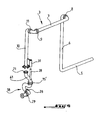
- the two missing rotary joints of the transfer device with six degrees of freedom and therefore six rotary joints are provided on the ship. These two rotation joints are part of the connection pipe 18 which is fixed on the manifold 2 and is formed by two 90 ° elbows 19, 20.
- the two remaining rotary joints designated by the references 26 and 27 are provided , 27, of the same axis as the manifold 2 which is connected to the elbow 19, the other 26 connecting the elbows 19 and 20.
- the axes of the rotating joints 26 and 27 are oriented perpendicularly to one another.
- the transfer system is equipped with a guiding and handling device, part of which is mounted on the articulated arm and another part on the connection pipe 18.
- This guiding device comprises, in known manner, a pinch 28 which is oriented by the tensile force of the cable 35 indicated below and mounted on a support arm 29 supported by the pipe element 20 to be shifted laterally. of the flange 21, and a trumpet 31 mounted on the connection device 4 being laterally offset by a support arm 32 of the service coupler 33 of the device 4.
- the supports 32 and 29 are such that the axis axis trumpet 31 / axis service coupler 33 and pinch pin 28 / flange axis 21 are identical. The cooperation of the trumpet and pinch ensures the parallelism of the flange face 21 and the face of the service coupler 33.
- the device further comprises a winch 34 mounted, in the example shown, on the upper part of the outer arm 10 of the articulated arm 3 and a cable 35 capable of being wound on this winch and brought by cable guides 36 through the trumpet 31 to be fixed, as in the example shown, at the end of the pinch 28.
- the winch could be removed at any other suitable place, for example on the support arm of the trumpet.
- the support arm 29 of the pinch 28 is provided at its end with a rotary indexing fork 38 intended to cooperate with a rotating indexing roller 39 secured to the trumpet 31 with an offset appropriate side corresponding to the offset of the fork 38 / pinoche 28. It is the cooperation of the roller 39 and the fork 38, which ensures the good coaxiality of the coupler 33 and the flange 21 by rotation about the common axis pinoche 28 / trumpet 31.
- the articulated arm 3 is balanced by means of a counterweight 41 disposed on an extension 42 of the internal arm 7.
- the balancing must be such that the handling cable is always in tension during the phases of connection / disconnection.
- the figures presented advantageously have arranged the different elements of the arm so that, whatever the angle of rotation of the rotating joints 8, 9, 11 and 15, the axis of the trumpet always intersects the axes of rotation of the rotating joints 9, 11 and 15.
- it will be attached during the production of such a system to arrange the elements of the outer arm 10 and transfer device 4 so as to bring the center of gravity of these elements at the axis of the trumpet 31 and as high as possible.
- the elements of the connection piping 18 have been arranged in such a way that the axis of the pinch always intersects the axes of rotation of the rotating joints 26 and 27.
- the six rotating joints give the system the six degrees of freedom required.
- the correct positioning of the arm 3 on the connection flange 21 of the manifold is ensured by the guiding device (28, 31, 38, 39), which allows the transfer system according to the invention to also be used at open sea despite the dynamic movements generated by the environment (swell, current, wind).
- the articulated arm can be less imposing and lighter.
- the figure 4 illustrates an embodiment of the transfer device according to the invention according to which three rotary joints corresponding to rotating joints 8, 9 and 11 of Figures 1 to 3 are located on the articulated arm 3, while the pipe 18 attached to the manifold comprises, additionally to the rotating joints 26, 27, a third rotary joint designated by the reference 15 'since it corresponds, functionally, to the rotary joint 15 of the Figures 1 to 3 .
- the pipe 18 comprises an additional portion in the form of a U 41, the seal 15 being placed in the base of this U-shaped portion so as always to comply with the advantageous geometric provisions mentioned above. It should be noted that, in the case where this component becomes available, the three-rotational arrangement could be replaced by a single fluid-flow ball joint which would reduce the bulk.
- FIGS 5 and 6 illustrate an embodiment of the invention according to which five rotary joints are provided on the articulated arm 3, namely the joints 8, 9, 11, 15 and 26 ', the latter seal corresponding functionally to the seal 26 of the Figures 1 to 3 .
- the seal 26 ' is disposed just upstream of the connection device 4.
- the sixth rotary joint 27 remains on the manifold pipe 18, in accordance with the Figures 1 to 3 .
- the figure 7 shows yet another embodiment whose particularity lies in the fact that the guide device and the connecting device of the articulated arm 3 are integrated so as to obtain a coaxial structure.
- the pinch 28 is arranged coaxially in the connection flange 21 of the pipe 18 attached to the manifold and the trumpet 31 is made in a tubular member 45 which is arranged coaxially in the connection opening 46 of the connection device extending into the axis thereof while the tube away from the end takes the form of a U allowing the tubular member 45 to open outwardly in the curved portion.
- the winch 34 is housed in the space defined by the U-tube, above the tubular member 45 of the trumpet 31 so that the cable can pass through the trumpet.
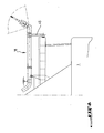
- connection flange 21 at the edge of the vessel and to be supported by a support 45 on the ship structure so as to transmit all or part of the efforts from the arm to the ship's structure and relieve the manifold of the ship, as illustrated by the figure 8 .
- connection device 4 of the articulated arm 3 comprises a service coupler 33 and an emergency disconnection device 43.
Description
L'invention concerne un système de transfert d'un fluide tel que du gaz naturel liquéfié entre un navire tel qu'un méthanier navette et une unité flottante ou fixe de production ou de stockage du fluide, du type à bras articulé et comportant n degrés de liberté, en général 6, chacun assuré par un joint tournant.The invention relates to a system for transferring a fluid such as liquefied natural gas between a vessel such as a shuttle methane tanker and a floating or fixed fluid production or storage unit of the articulated arm type with n degrees of freedom, in general 6, each ensured by a rotating joint.
Un système de ce type est connu par le document
L'invention a pour but de pallier cet inconvénient.The invention aims to overcome this disadvantage.
Pour atteindre ce but, le système de transfert selon l'invention est caractérisé en ce qu'au moins un joint rotatif est prévu sur le navire.To achieve this purpose, the transfer system according to the invention is characterized in that at least one rotary joint is provided on the ship.
Ce but est atteint grâce aux caractéristiques qui sont énoncées dans la partie caractérisante de la revendication 1.This object is achieved by virtue of the features which are set forth in the characterizing part of
D'autres caractéristiques de l'invention sont énoncées dans des revendications dépendantes.Other features of the invention are set forth in dependent claims.
L'invention sera mieux comprise, et d'autres buts, caractéristiques, détails et avantages de celle-ci apparaîtront plus clairement au cours de la description explicative qui va suivre faite en référence aux dessins schématiques annexés, donnés uniquement à titre d'exemple, illustrant plusieurs modes de réalisation de l'invention et dans lesquels :
- la
figure 1 est une vue en élévation d'un système de transfert selon l'invention ; - la
figure 2 est une vue latérale de ce même système de transfert, en direction de la flèche II de lafigure 1 ; - la
figure 3 est un schéma cinématique du système de transfert selon l'invention ; - la
figure 4 est une vue schématique d'un autre mode de réalisation du système de transfert selon l'invention ; - les
figures 5 et 6 sont respectivement une vue en élévation et une vue latérale d'encore un autre mode de réalisation de l'invention ; - la
figure 7 illustre encore un autre mode de réalisation du système de transfert selon l'invention ; et - la
figure 8 illustre le rallongement du manifold jusqu'au bord du navire.
- the
figure 1 is an elevational view of a transfer system according to the invention; - the
figure 2 is a side view of this same transfer system, in the direction of arrow II of thefigure 1 ; - the
figure 3 is a kinematic diagram of the transfer system according to the invention; - the
figure 4 is a schematic view of another embodiment of the transfer system according to the invention; - the
Figures 5 and 6 are respectively an elevational view and a side view of yet another embodiment of the invention; - the
figure 7 illustrates yet another embodiment of the transfer system according to the invention; and - the
figure 8 illustrates the extension of the manifold to the edge of the ship.
L'invention sera décrite ci-après dans un mode de réalisation selon lequel deux joints rotatifs du système sont prévus sur le navire. De façon analogue, conformément à l'invention, il est envisageable de prévoir trois joints rotatifs ou seulement un sur le navire.The invention will be described hereinafter in an embodiment according to which two rotary joints of the system are provided on the ship. Similarly, according to the invention, it is conceivable to provide three rotary joints or only one on the ship.
Sur les figures, la référence 1 désigne un navire tel qu'un méthanier navette, 2 le manifold du navire, 3 un bras de transfert articulé qui comporte à son extrémité libre un dispositif de connexion / déconnexion au manifold, désigné par la référence 4 et dont l'autre extrémité est reliée à la tuyauterie 5 de l'unité de production ou de stockage. Cette unité pourrait être flottante ou fixe. La figure montre le système de transfert au cours d'une connexion au manifold du navire.In the figures,
Le bras articulé 3 comporte essentiellement trois segments de tuyauterie articulés les uns aux autres, à savoir un premier segment de support 6 dont l'extrémité libre est reliée à la tuyauterie 5, un deuxième segment de bras 7, dit bras interne, qui est relié au segment 6 par un premier joint tournant 8 et dont l'autre extrémité est reliée par un deuxième joint tournant 9 à un coude 12 à 90 degrés relié par son autre extrémité à un troisième joint tournant 11 qui relie ce coude au troisième segment de bras 10, dit bras externe. L'extrémité inférieure libre du bras externe est reliée par un quatrième joint tournant 15 au dispositif de connexion 4.The articulated
Il est à noter que l'axe de rotation du joint tournant 9 est perpendiculaire à l'axe de rotation du joint 8, l'axe du joint tournant 11 est perpendiculaire à l'axe du joint 9 et l'axe du joint 15 est perpendiculaire à celui du joint 11. La figure schématique 3 fait clairement apparaître ces orientations des quatre joints rotatifs du bras articulé 3, ainsi que la disposition relative des différents coudes et pièces d'interconnexion.It should be noted that the axis of rotation of the
Les deux joints rotatifs manquants du dispositif de transfert à six degrés de liberté et donc six joints rotatifs sont prévus sur le navire. Ces deux joints de rotation font partie de la tuyauterie de connexion 18 qui est fixée sur le manifold 2 et est formée par deux coudes à 90° 19, 20. Les deux joints tournants restants désignés par les références 26 et 27 sont prévus l'un, 27, de même axe que le manifold 2 auquel est relié le coude 19, l'autre 26 reliant les coudes 19 et 20. Les axes des joints tournants 26 et 27 sont orientés perpendiculairement l'un à l'autre.The two missing rotary joints of the transfer device with six degrees of freedom and therefore six rotary joints are provided on the ship. These two rotation joints are part of the
Le système de transfert est équipé d'un dispositif de guidage et de manutention dont une partie est montée sur le bras articulé et une autre sur la tuyauterie de connexion 18.The transfer system is equipped with a guiding and handling device, part of which is mounted on the articulated arm and another part on the
Ce dispositif de guidage comporte, de façon connue en soi, une pinoche 28 qui est orientée par l'effort de traction du câble 35 indiquée plus loin et montée sur un bras de support 29 supporté par l'élément de tuyauterie 20 pour être décalé latéralement de la bride 21, et une trompette 31 montée sur le dispositif de connexion 4 en étant latéralement déportée par un bras de support 32 du coupleur de service 33 du dispositif 4. Les supports 32 et 29 sont tels que les entraxes axe trompette 31 / axe coupleur de service 33 et axe pinoche 28 / axe bride 21 sont identiques. La coopération de la trompette et de la pinoche assure le parallélisme de la face de bride 21 et de la face du coupleur de service 33.This guiding device comprises, in known manner, a
Le dispositif comporte en outre un treuil 34 monté, dans l'exemple représenté, sur la partie supérieure du bras extérieur 10 du bras articulé 3 et un câble 35 susceptible d'être enroulé sur ce treuil et amené par des guide-câbles 36 à travers la trompette 31 pour être fixé, comme dans l'exemple représenté, à l'extrémité de la pinoche 28. Bien entendu, le treuil pourrait être déposé à tout autre endroit approprié, par exemple sur le bras de support de la trompette.The device further comprises a
Pour assurer un positionnement correct, le bras de support 29 de la pinoche 28 est pourvu à son extrémité d'une fourche d'indexage en rotation 38 destinée à coopérer avec un galet d'indexage en rotation 39 solidaire de la trompette 31 avec un déport latéral approprié correspondant au déport de la fourche 38 /pinoche 28. C'est la coopération du galet 39 et de la fourche 38, qui assure la bonne coaxialité du coupleur 33 et de la bride 21 par rotation autour de l'axe commun pinoche 28 / trompette 31.To ensure correct positioning, the
Il est encore à noter que le bras articulé 3 est équilibré à l'aide d'un contrepoids 41 disposé sur un prolongement 42 du bras interne 7. L'équilibrage doit être tel que le câble de manutention est toujours en tension lors des phases de connexion / déconnexion.It should also be noted that the articulated
Il est à noter que dans un souci d'optimisation de la manutention, on a, dans les figures présentées, avantagement disposé les différents éléments du bras de telle sorte que, quelque soit l'angle de rotation des joints tournants 8, 9, 11 et 15, l'axe de la trompette coupe toujours les axes de rotation des joints tournants 9, 11 et 15. De plus, on s'attachera lors de la réalisation d'un tel système, à disposer les éléments du bras externe 10 et du dispositif de transfert 4 de façon à amener le centre de gravité de ces éléments au niveau de l'axe de la trompette 31 et le plus haut possible. De même, côté manifold, les éléments de la tuyauterie de connexion 18 ont été disposés de telle sorte que l'axe de la pinoche coupe toujours les axes de rotation des joints tournants 26 et 27. On pourra de plus, lors de la réalisation de la tuyauterie de connexion 18, l'équilibrer à l'aide de contrepoids ou de dispositifs élastique (de type ressorts par exemple). L'ensemble de ces dispositions permet d'optimiser l'alignement du câble de manutention, de l'axe de la pinoche et de l'axe de la trompette quelque que soit la position relative entre le navire et l'unité de stockage ou de production et leurs mouvements.It should be noted that, for the sake of optimizing the handling, the figures presented advantageously have arranged the different elements of the arm so that, whatever the angle of rotation of the
Concernant le fonctionnement du système de transfert selon l'invention, on comprend aisément que les six joints tournants confèrent au système les six degrés de liberté nécessaires. Le positionnement correct du bras 3 sur la bride de connexion 21 du manifold est assuré par le dispositif de guidage (28, 31, 38, 39), ce qui permet au système de transfert selon l'invention d'être également utilisé en mer ouverte malgré les mouvements dynamiques engendrés par l'environnement (houle, courant, vent). En disposant une partie des joints tournants sur le navire, le bras articulé peut être moins imposant et plus léger.Regarding the operation of the transfer system according to the invention, it is easy to understand that the six rotating joints give the system the six degrees of freedom required. The correct positioning of the
La
Les
La
Il est encore à noter que la tuyauterie 18 fixée au manifold pourrait être suffisamment longue pour déporter la bride de connexion 21 au niveau du bord du navire et venir prendre appui par un support 45 sur la structure du navire de façon à transmettre tout ou partie des efforts du bras à la structure du navire et soulager le manifold du navire, comme l'illustre la
Pour compléter la description, il est à noter que le dispositif de connexion 4 du bras articulé 3 comporte un coupleur de service 33 et un dispositif de déconnexion d'urgence 43.To complete the description, it should be noted that the connection device 4 of the articulated
Claims (6)
- A system for transferring a fluid such as liquefied natural gas between a vessel such as a liquefied natural gas shuttle carrier and a floating or fixed fluid production and/or storage unit, this system being of the type with n degrees of freedom, generally six, each materialised by a rotating joint, and comprising an articulated arm system mounted on the floating or fixed unit, whilst the vessel comprises a manifold to which the articulated arm must be connectable, characterized in that it comprises connection piping (18) which is formed by at least one elbow-shaped part comprising at least one (27, 26, 15') of the rotating joints and is secured via one end to the manifold (2) and whose other end carries a connecting flange (21) to the articulated arm (3).
- The transfer system according to claim 1, characterized in that the articulated arm (3) comprises a supporting segment (6) connected to fixed piping (5) of the floating or fixed unit, an outer arm segment (7) and an inner arm segment (10) which comprise at least three rotating joints (8, 9, 11) whilst the three other rotating joints (26, 27, 15) are provided on the piping (18) fixed to the manifold and whose end carries the connecting flange (21) of the articulated arm (3).
- The transfer system according to one of claims 1 and 2, characterized in that the articulated arm (3) and the fixed piping (18) of the manifold comprise elbows and U-shaped parts adapted to ensure suitable orientation of the rotation axes of the rotating joints.
- The transfer system according to one of claims 1 to 3, characterized in that it comprises a device for guiding and handling the connection device (4) of the articulated arm (10) of cone (28) and trumpet (31) type, arranged laterally to the connection device.
- The transfer system according to one of claims 1 to 3 characterized in that it comprises a device for guiding and handling the connection device (4) of cone (28) and trumpet (31) type which is integrated coaxially to the connecting means.
- The transfer system according to claim 6 characterized in that the trumpet (31) is provided on the connection piping (18) and is arranged so that its axis at all times cuts across the rotation axes of the rotating joints provided on the piping (18) and the rotation axes of the rotating joints provided on and adjacent to the articulated arm (10) whose end is connectable to the connecting flange of the piping (18).
Applications Claiming Priority (2)
| Application Number | Priority Date | Filing Date | Title |
|---|---|---|---|
| FR0652985A FR2903653B1 (en) | 2006-07-13 | 2006-07-13 | SYSTEM FOR TRANSFERRING A FLUID SUCH AS LIQUEFIED NATURAL GAS BETWEEN A SHIP, SUCH AS A SHUTTLE METHANIER AND A FLOATING OR FIXED UNIT. |
| PCT/FR2007/051656 WO2008007033A1 (en) | 2006-07-13 | 2007-07-12 | System for transfer of a liquid such as liquefied natural gas from a ship such as a liquefied natural gas carrier and a floating or fixed unit |
Publications (2)
| Publication Number | Publication Date |
|---|---|
| EP2043910A1 EP2043910A1 (en) | 2009-04-08 |
| EP2043910B1 true EP2043910B1 (en) | 2012-09-12 |
Family
ID=37888403
Family Applications (1)
| Application Number | Title | Priority Date | Filing Date |
|---|---|---|---|
| EP20070823577 Not-in-force EP2043910B1 (en) | 2006-07-13 | 2007-07-12 | System for transfer of a liquid such as liquefied natural gas from a ship such as a liquefied natural gas carrier and a floating or fixed unit |
Country Status (13)
| Country | Link |
|---|---|
| US (1) | US8881538B2 (en) |
| EP (1) | EP2043910B1 (en) |
| JP (1) | JP5303460B2 (en) |
| KR (1) | KR101373740B1 (en) |
| CN (1) | CN101489864A (en) |
| AU (1) | AU2007274112B9 (en) |
| BR (1) | BRPI0715464A2 (en) |
| ES (1) | ES2403532T3 (en) |
| FR (1) | FR2903653B1 (en) |
| MY (1) | MY150203A (en) |
| NO (1) | NO20090727L (en) |
| RU (1) | RU2455224C2 (en) |
| WO (1) | WO2008007033A1 (en) |
Families Citing this family (23)
| Publication number | Priority date | Publication date | Assignee | Title |
|---|---|---|---|---|
| FR2854156B1 (en) | 2003-04-23 | 2007-03-09 | Fmc Technologies Sa | ARTICULATED-ARM ASSEMBLY COMPRISING A CONNECTING CABLE FOR LOADING AND UNLOADING PRODUCTS, IN PARTICULAR FLUID PRODUCTS |
| WO2009052853A1 (en) * | 2007-10-22 | 2009-04-30 | Bluewater Energy Services B.V. | Fluid transfer assembly |
| KR101069659B1 (en) | 2008-11-11 | 2011-10-04 | 삼성중공업 주식회사 | Lng transfer device |
| FR2945024A1 (en) * | 2009-04-30 | 2010-11-05 | Eurodim Sa | ARRANGEMENT FOR TRANSFERRING A FLUID TO A SHIP AND A SYSTEM FOR TRANSFERRING A FLUID BETWEEN TWO SHIPS, ONE OF WHICH IS EQUIPPED WITH AN ARRANGEMENT ACCORDING TO THE INVENTION |
| FR2945510B1 (en) * | 2009-05-13 | 2014-11-07 | Eurodim Sa | METHOD OF TRANSFERRING FLUIDS BETWEEN A FIRST VESSEL AND A SECOND VESSEL AND TRANSFER SYSTEM FOR CARRYING OUT SAID METHOD |
| JP2012025466A (en) * | 2010-07-27 | 2012-02-09 | Niigata Loading Systems Ltd | Fluid cargo handling device for ship delivery |
| KR200465533Y1 (en) * | 2010-09-01 | 2013-02-25 | 삼성중공업 주식회사 | Connecting structure of transfer pipe for liquefied gas |
| CN102000967B (en) * | 2010-09-07 | 2013-01-09 | 电子科技大学 | Adaptor device for synchronous butt joint of main cone nut and flange of automobile drive axle assembly |
| FR2966553B1 (en) * | 2010-10-26 | 2015-01-02 | Ksb Sas | CONNECTING DEVICE WITH FREEZING CLAMP MODULES. |
| DE102012212916A1 (en) * | 2012-07-24 | 2014-01-30 | Putzmeister Engineering Gmbh | Rotary distributor for thick materials |
| CA2884639A1 (en) * | 2012-09-14 | 2014-03-20 | The Government of the United State of America as represented by the Secretary of the Navy | Magnetically attracted connector system and method |
| DE102012222084B4 (en) | 2012-12-03 | 2017-06-01 | FR. LÜRSSEN WERFT GmbH & Co.KG | Device for passing a fluid into a tank and a ship equipped with such a device |
| FR3003855B1 (en) * | 2013-03-29 | 2016-01-29 | Fmc Technologies Sa | TRANSFER ARM OF A FLUID PRODUCT FROM SHIP TO SHIP |
| FR3010044B1 (en) * | 2013-08-30 | 2017-05-05 | Technip France | FLUID SYSTEM BETWEEN A FIXED OR FLOATING SYSTEM FOR THE PRODUCTION OR STORAGE OF FLUID AND A VESSEL SUCH AS A METHANIER SHUTTLE |
| FR3012411B1 (en) * | 2013-10-31 | 2016-08-05 | Gaztransport Et Technigaz | SYSTEM FOR TRANSFERRING FLUID BETWEEN A SHIP AND A FACILITY, SUCH AS A CLIENT SHIP |
| CN104747842B (en) * | 2013-12-30 | 2017-01-18 | 宝钢工程技术集团有限公司 | Universal displacement connecting device of thermodynamic pipeline |
| ES2504916B2 (en) * | 2014-01-29 | 2015-03-03 | Univ Madrid Politecnica | Rotary joint to assemble fixed tubes with rotary tubes |
| FR3017127B1 (en) * | 2014-01-31 | 2016-02-05 | Gaztransp Et Technigaz | SYSTEM FOR TRANSFERRING LNG FROM A SHIP TO A FACILITY |
| US9598152B2 (en) | 2014-04-01 | 2017-03-21 | Moran Towing Corporation | Articulated conduit systems and uses thereof for fluid transfer between two vessels |
| FR3051782B1 (en) * | 2016-05-24 | 2018-07-06 | Fmc Technologies Sa | DISPLACEMENT CONTROL DEVICE, ACQUISITION AND CALCULATION METHOD AND DEVICE THEREFOR, AND ARTICULATED FLUID LOADING ARM COMPRISING SAME. |
| NO342287B1 (en) | 2016-07-18 | 2018-04-30 | Macgregor Norway As | Coupling system for transfer of hydrocarbons at open sea |
| CN110167836B (en) * | 2017-01-16 | 2021-09-14 | 三星重工业株式会社 | Floating structure |
| CN109307154A (en) * | 2017-07-27 | 2019-02-05 | 中国船舶重工集团公司第七〇九研究所 | A kind of fluid delivery system for single point mooring unit |
Family Cites Families (18)
| Publication number | Priority date | Publication date | Assignee | Title |
|---|---|---|---|---|
| US4066098A (en) * | 1976-10-08 | 1978-01-03 | Exxon Research & Engineering Co. | Marine loading and bunkering arrangement |
| FR2367700A1 (en) * | 1976-10-15 | 1978-05-12 | Emh | IMPROVEMENTS CONTRIBUTION |
| FR2368399A1 (en) * | 1976-10-19 | 1978-05-19 | Emh | IMPROVEMENTS TO EQUIPMENT TO CONNECT OIL TANKERS TO MARINE OR SIMILAR COLUMNS |
| GB1592073A (en) * | 1977-02-08 | 1981-07-01 | Fmc Corp | Fluid loading systems |
| US4299261A (en) * | 1978-12-11 | 1981-11-10 | Fmc Corporation | Offshore loading system |
| FR2474012B2 (en) * | 1979-05-28 | 1986-01-31 | Fmc Europe | COUPLING AND TRANSFER MEANS FOR ARTICULATED LOADING ARMS FOR TRANSFERRING FLUIDS |
| US4393906A (en) * | 1979-10-01 | 1983-07-19 | Fmc Corporation | Stern to bow offshore loading system |
| US4408943A (en) * | 1981-02-27 | 1983-10-11 | Fmc Corporation | Ship-to-ship fluid transfer system |
| NO318172B1 (en) * | 1990-01-30 | 2005-02-14 | Advanced Prod & Loading As | Loading arrangement for loading fluids in an offshore vessel |
| EP0947464A1 (en) * | 1998-04-01 | 1999-10-06 | Single Buoy Moorings Inc. | Fluid transfer boom with coaxial fluid ducts |
| FR2813872B1 (en) * | 2000-09-14 | 2003-01-31 | Fmc Europe | ARTICULATED ARM FOR LOADING AND UNLOADING PRODUCTS, PARTICULARLY FLUID PRODUCTS |
| FR2815025B1 (en) * | 2000-10-06 | 2003-08-29 | Eurodim Sa | SYSTEM FOR TRANSFERRING A FLUID PRODUCT, IN PARTICULAR LIQUEFIED NATURAL GAS AT CRYOGENIC TEMPERATURE, BETWEEN A TRANSPORT VESSEL AND A LAND TREATMENT AND STORAGE FACILITY FOR THIS PRODUCT |
| FR2824529B1 (en) * | 2001-05-11 | 2003-08-29 | Eurodim Sa | SYSTEM FOR TRANSFERRING A FLUID PRODUCT, ESPECIALLY LIQUEFIED GAS, BETWEEN A TRANSPORT VEHICLE SUCH AS A VESSEL AND A RECEPTION OR SUPPLY FACILITY FOR THIS PRODUCT |
| FR2827033B1 (en) * | 2001-07-03 | 2004-08-20 | Eurodim Sa | ARRANGEMENT FOR CONNECTING AND DISCONNECTING TWO PIPE LINES OF A FLUID TRANSFER SYSTEM |
| FR2831514B1 (en) * | 2001-10-30 | 2004-03-12 | Eurodim Sa | SYSTEM FOR TRANSPORTING A FLUID BETWEEN A TRANSPORT VESSEL AND A STORAGE STATION SUCH AS A STORAGE VESSEL |
| FR2845753B1 (en) * | 2002-10-11 | 2005-08-05 | Eurodim Sa | ROTATING JOINT SYSTEM FOR MOUNTING IN A TRANSFER LINE OF A CRYOGENIC LIQUID, SUCH AS LIQUEFIED NATURAL GAS, AND COLD GAS RETURN LINKED TO THE TRANSFER OF CRYOGENIC LIQUID |
| WO2005105556A1 (en) | 2004-04-26 | 2005-11-10 | Gunter Herbert D | Protective chain for endless drive-belts |
| WO2007113203A1 (en) * | 2006-03-30 | 2007-10-11 | Single Buoy Moorings Inc. | Hydrocarbon transfer system with vertical rotation axis |
-
2006
- 2006-07-13 FR FR0652985A patent/FR2903653B1/en not_active Expired - Fee Related
-
2007
- 2007-07-12 EP EP20070823577 patent/EP2043910B1/en not_active Not-in-force
- 2007-07-12 BR BRPI0715464-0A patent/BRPI0715464A2/en not_active IP Right Cessation
- 2007-07-12 AU AU2007274112A patent/AU2007274112B9/en not_active Ceased
- 2007-07-12 RU RU2009102301/11A patent/RU2455224C2/en not_active IP Right Cessation
- 2007-07-12 KR KR1020097000669A patent/KR101373740B1/en not_active IP Right Cessation
- 2007-07-12 US US12/373,069 patent/US8881538B2/en not_active Expired - Fee Related
- 2007-07-12 CN CNA2007800264629A patent/CN101489864A/en active Pending
- 2007-07-12 JP JP2009518940A patent/JP5303460B2/en not_active Expired - Fee Related
- 2007-07-12 MY MYPI20090066A patent/MY150203A/en unknown
- 2007-07-12 ES ES07823577T patent/ES2403532T3/en active Active
- 2007-07-12 WO PCT/FR2007/051656 patent/WO2008007033A1/en active Application Filing
-
2009
- 2009-02-13 NO NO20090727A patent/NO20090727L/en not_active Application Discontinuation
Also Published As
| Publication number | Publication date |
|---|---|
| CN101489864A (en) | 2009-07-22 |
| JP5303460B2 (en) | 2013-10-02 |
| AU2007274112A1 (en) | 2008-01-17 |
| WO2008007033A1 (en) | 2008-01-17 |
| ES2403532T3 (en) | 2013-05-20 |
| KR20090029263A (en) | 2009-03-20 |
| AU2007274112B2 (en) | 2013-03-07 |
| RU2009102301A (en) | 2010-08-20 |
| EP2043910A1 (en) | 2009-04-08 |
| FR2903653A1 (en) | 2008-01-18 |
| US8881538B2 (en) | 2014-11-11 |
| NO20090727L (en) | 2009-02-13 |
| RU2455224C2 (en) | 2012-07-10 |
| US20090205343A1 (en) | 2009-08-20 |
| JP2009542544A (en) | 2009-12-03 |
| KR101373740B1 (en) | 2014-03-25 |
| MY150203A (en) | 2013-12-13 |
| AU2007274112B9 (en) | 2013-06-20 |
| BRPI0715464A2 (en) | 2013-03-19 |
| FR2903653B1 (en) | 2009-04-10 |
Similar Documents
| Publication | Publication Date | Title |
|---|---|---|
| EP2043910B1 (en) | System for transfer of a liquid such as liquefied natural gas from a ship such as a liquefied natural gas carrier and a floating or fixed unit | |
| EP2040975B1 (en) | Device for connecting the end of a flexible liquid supply pipe to a fixed tubing such as the manifold on a ship | |
| FR2945510A1 (en) | METHOD OF TRANSFERRING FLUIDS BETWEEN A FIRST VESSEL AND A SECOND VESSEL AND TRANSFER SYSTEM FOR CARRYING OUT SAID METHOD | |
| FR2876142A1 (en) | DEVICE FOR CONNECTING SUPERIOR BETWEEN TWO SUB-MARINE CONDUITS OF FLUID TRANSPORT | |
| FR2928979A1 (en) | DEVICE FOR CONTROLLING AUBES WITH VARIABLE TIMING IN A TURBOMACHINE. | |
| EP0043304B1 (en) | Device for the filtration of the vibrations of a motor | |
| EP2424777A2 (en) | Arrangement for transferring a fluid to a ship and system for transferring fluid between two ships, one of which is provided with the arrangement of the invention | |
| EP1586801B1 (en) | Method and device for placing a branch pipe fitting onto a pipe | |
| EP1439999B1 (en) | Fluid transfer system between a transport vessel and a storage station such as a storage vessel | |
| FR2578024A1 (en) | PIVOTLESS COUPLING APPARATUS FOR COUPLING A CONDUIT FIXED TO A MOBILE SUPPORT IN THE MARINE ENVIRONMENT | |
| CA2501866C (en) | Swivel joint system | |
| EP1678435A1 (en) | Guide tube for a flexible duct for transporting hydrocarbons | |
| WO2010116113A2 (en) | System for transferring fluids between two vessels placed side by side | |
| WO2002092422A1 (en) | System for transferring a fluid product, in particular a liquefied natural gas, between a transport vehicle such as a ship and an installation receiving or supplying said product | |
| FR2915456A1 (en) | UNDERWATER BUOY WITH MODULAR ELEMENTS. | |
| FR2761751A1 (en) | CONNECTING SLEEVE TO EQUIPMENT, PARTICULARLY TO A PIPE | |
| FR2965559A1 (en) | FLUID TRANSFER INSTALLATION | |
| FR2837190A1 (en) | System for transferring fluid, e.g. liquefied natural gas, between fluid transport vessel and storage point, e.g. storage vessel, comprises flexible fluid transfer pipe | |
| EP4022175A1 (en) | Bellcrank for a variable adjustment device for a turbomachine | |
| FR2749919A1 (en) | CONNECTION DEVICE | |
| EP3038895B1 (en) | System for transferring fluid between a fixed or floating facility for producing or storing fluid and a vessel such as a liquid natural gas carrier | |
| EP3820772B1 (en) | Liquefied gas transfer system | |
| EP4253823A1 (en) | Device for holding at least one component on a tower for loading and/or unloading a vessel of a vessel intended to contain a liquefied gas | |
| FR2589425A1 (en) | CONTROL UNIT FOR A MOTOR AND A TRANSMISSION WITH A SINGLE LEVER | |
| FR2990426A1 (en) | Protection device for protecting connection cable of proximity sensor for coupler of tank car connection arm of hydrocarbon loading system, has coupling placed at fixing points of rigid tubular portion on portion of loading arm |
Legal Events
| Date | Code | Title | Description |
|---|---|---|---|
| PUAI | Public reference made under article 153(3) epc to a published international application that has entered the european phase |
Free format text: ORIGINAL CODE: 0009012 |
|
| 17P | Request for examination filed |
Effective date: 20090115 |
|
| AK | Designated contracting states |
Kind code of ref document: A1 Designated state(s): AT BE BG CH CY CZ DE DK EE ES FI FR GB GR HU IE IS IT LI LT LU LV MC MT NL PL PT RO SE SI SK TR |
|
| AX | Request for extension of the european patent |
Extension state: AL BA HR MK RS |
|
| 17Q | First examination report despatched |
Effective date: 20100723 |
|
| GRAP | Despatch of communication of intention to grant a patent |
Free format text: ORIGINAL CODE: EPIDOSNIGR1 |
|
| RIC1 | Information provided on ipc code assigned before grant |
Ipc: B67D 9/02 20100101ALI20120320BHEP Ipc: B63B 27/24 20060101AFI20120320BHEP |
|
| DAX | Request for extension of the european patent (deleted) | ||
| GRAS | Grant fee paid |
Free format text: ORIGINAL CODE: EPIDOSNIGR3 |
|
| GRAA | (expected) grant |
Free format text: ORIGINAL CODE: 0009210 |
|
| AK | Designated contracting states |
Kind code of ref document: B1 Designated state(s): AT BE BG CH CY CZ DE DK EE ES FI FR GB GR HU IE IS IT LI LT LU LV MC MT NL PL PT RO SE SI SK TR |
|
| REG | Reference to a national code |
Ref country code: GB Ref legal event code: FG4D Free format text: NOT ENGLISH |
|
| REG | Reference to a national code |
Ref country code: CH Ref legal event code: EP |
|
| REG | Reference to a national code |
Ref country code: AT Ref legal event code: REF Ref document number: 574921 Country of ref document: AT Kind code of ref document: T Effective date: 20120915 |
|
| REG | Reference to a national code |
Ref country code: IE Ref legal event code: FG4D Free format text: LANGUAGE OF EP DOCUMENT: FRENCH |
|
| REG | Reference to a national code |
Ref country code: DE Ref legal event code: R096 Ref document number: 602007025479 Country of ref document: DE Effective date: 20121108 |
|
| REG | Reference to a national code |
Ref country code: NL Ref legal event code: T3 |
|
| PG25 | Lapsed in a contracting state [announced via postgrant information from national office to epo] |
Ref country code: LT Free format text: LAPSE BECAUSE OF FAILURE TO SUBMIT A TRANSLATION OF THE DESCRIPTION OR TO PAY THE FEE WITHIN THE PRESCRIBED TIME-LIMIT Effective date: 20120912 Ref country code: FI Free format text: LAPSE BECAUSE OF FAILURE TO SUBMIT A TRANSLATION OF THE DESCRIPTION OR TO PAY THE FEE WITHIN THE PRESCRIBED TIME-LIMIT Effective date: 20120912 Ref country code: CY Free format text: LAPSE BECAUSE OF FAILURE TO SUBMIT A TRANSLATION OF THE DESCRIPTION OR TO PAY THE FEE WITHIN THE PRESCRIBED TIME-LIMIT Effective date: 20120912 |
|
| REG | Reference to a national code |
Ref country code: AT Ref legal event code: MK05 Ref document number: 574921 Country of ref document: AT Kind code of ref document: T Effective date: 20120912 |
|
| REG | Reference to a national code |
Ref country code: LT Ref legal event code: MG4D Effective date: 20120912 |
|
| PG25 | Lapsed in a contracting state [announced via postgrant information from national office to epo] |
Ref country code: LV Free format text: LAPSE BECAUSE OF FAILURE TO SUBMIT A TRANSLATION OF THE DESCRIPTION OR TO PAY THE FEE WITHIN THE PRESCRIBED TIME-LIMIT Effective date: 20120912 Ref country code: SI Free format text: LAPSE BECAUSE OF FAILURE TO SUBMIT A TRANSLATION OF THE DESCRIPTION OR TO PAY THE FEE WITHIN THE PRESCRIBED TIME-LIMIT Effective date: 20120912 Ref country code: GR Free format text: LAPSE BECAUSE OF FAILURE TO SUBMIT A TRANSLATION OF THE DESCRIPTION OR TO PAY THE FEE WITHIN THE PRESCRIBED TIME-LIMIT Effective date: 20121213 Ref country code: SE Free format text: LAPSE BECAUSE OF FAILURE TO SUBMIT A TRANSLATION OF THE DESCRIPTION OR TO PAY THE FEE WITHIN THE PRESCRIBED TIME-LIMIT Effective date: 20120912 |
|
| PG25 | Lapsed in a contracting state [announced via postgrant information from national office to epo] |
Ref country code: EE Free format text: LAPSE BECAUSE OF FAILURE TO SUBMIT A TRANSLATION OF THE DESCRIPTION OR TO PAY THE FEE WITHIN THE PRESCRIBED TIME-LIMIT Effective date: 20120912 Ref country code: RO Free format text: LAPSE BECAUSE OF FAILURE TO SUBMIT A TRANSLATION OF THE DESCRIPTION OR TO PAY THE FEE WITHIN THE PRESCRIBED TIME-LIMIT Effective date: 20120912 Ref country code: CZ Free format text: LAPSE BECAUSE OF FAILURE TO SUBMIT A TRANSLATION OF THE DESCRIPTION OR TO PAY THE FEE WITHIN THE PRESCRIBED TIME-LIMIT Effective date: 20120912 Ref country code: IS Free format text: LAPSE BECAUSE OF FAILURE TO SUBMIT A TRANSLATION OF THE DESCRIPTION OR TO PAY THE FEE WITHIN THE PRESCRIBED TIME-LIMIT Effective date: 20130112 |
|
| REG | Reference to a national code |
Ref country code: ES Ref legal event code: FG2A Ref document number: 2403532 Country of ref document: ES Kind code of ref document: T3 Effective date: 20130520 |
|
| PG25 | Lapsed in a contracting state [announced via postgrant information from national office to epo] |
Ref country code: PL Free format text: LAPSE BECAUSE OF FAILURE TO SUBMIT A TRANSLATION OF THE DESCRIPTION OR TO PAY THE FEE WITHIN THE PRESCRIBED TIME-LIMIT Effective date: 20120912 Ref country code: PT Free format text: LAPSE BECAUSE OF FAILURE TO SUBMIT A TRANSLATION OF THE DESCRIPTION OR TO PAY THE FEE WITHIN THE PRESCRIBED TIME-LIMIT Effective date: 20130114 Ref country code: SK Free format text: LAPSE BECAUSE OF FAILURE TO SUBMIT A TRANSLATION OF THE DESCRIPTION OR TO PAY THE FEE WITHIN THE PRESCRIBED TIME-LIMIT Effective date: 20120912 |
|
| RAP2 | Party data changed (patent owner data changed or rights of a patent transferred) |
Owner name: TECHNIP FRANCE |
|
| REG | Reference to a national code |
Ref country code: DE Ref legal event code: R082 Ref document number: 602007025479 Country of ref document: DE Representative=s name: RECHTS- UND PATENTANWAELTE LORENZ SEIDLER GOSS, DE |
|
| PG25 | Lapsed in a contracting state [announced via postgrant information from national office to epo] |
Ref country code: AT Free format text: LAPSE BECAUSE OF FAILURE TO SUBMIT A TRANSLATION OF THE DESCRIPTION OR TO PAY THE FEE WITHIN THE PRESCRIBED TIME-LIMIT Effective date: 20120912 |
|
| PLBE | No opposition filed within time limit |
Free format text: ORIGINAL CODE: 0009261 |
|
| STAA | Information on the status of an ep patent application or granted ep patent |
Free format text: STATUS: NO OPPOSITION FILED WITHIN TIME LIMIT |
|
| PG25 | Lapsed in a contracting state [announced via postgrant information from national office to epo] |
Ref country code: DK Free format text: LAPSE BECAUSE OF FAILURE TO SUBMIT A TRANSLATION OF THE DESCRIPTION OR TO PAY THE FEE WITHIN THE PRESCRIBED TIME-LIMIT Effective date: 20120912 Ref country code: BG Free format text: LAPSE BECAUSE OF FAILURE TO SUBMIT A TRANSLATION OF THE DESCRIPTION OR TO PAY THE FEE WITHIN THE PRESCRIBED TIME-LIMIT Effective date: 20121212 |
|
| REG | Reference to a national code |
Ref country code: NL Ref legal event code: SD Effective date: 20130729 |
|
| REG | Reference to a national code |
Ref country code: DE Ref legal event code: R082 Ref document number: 602007025479 Country of ref document: DE Representative=s name: RECHTS- UND PATENTANWAELTE LORENZ SEIDLER GOSS, DE Effective date: 20130625 Ref country code: DE Ref legal event code: R082 Ref document number: 602007025479 Country of ref document: DE Representative=s name: LORENZ SEIDLER GOSSEL RECHTSANWAELTE PATENTANW, DE Effective date: 20130625 Ref country code: DE Ref legal event code: R081 Ref document number: 602007025479 Country of ref document: DE Owner name: TECHNIP FRANCE, FR Free format text: FORMER OWNER: SOCIETE EUROPEENNE D'INGENIERIE MECANIQUE: EURODIM, RUEIL MALMAISON, FR Effective date: 20130625 |
|
| 26N | No opposition filed |
Effective date: 20130613 |
|
| REG | Reference to a national code |
Ref country code: GB Ref legal event code: 732E Free format text: REGISTERED BETWEEN 20130815 AND 20130821 |
|
| REG | Reference to a national code |
Ref country code: DE Ref legal event code: R097 Ref document number: 602007025479 Country of ref document: DE Effective date: 20130613 |
|
| PGFP | Annual fee paid to national office [announced via postgrant information from national office to epo] |
Ref country code: ES Payment date: 20130830 Year of fee payment: 7 Ref country code: IE Payment date: 20130724 Year of fee payment: 7 |
|
| PGFP | Annual fee paid to national office [announced via postgrant information from national office to epo] |
Ref country code: GB Payment date: 20130731 Year of fee payment: 7 |
|
| BERE | Be: lapsed |
Owner name: SOC. EUROPEENNE D' INGENIERIE MECANIQUE - EURODIM Effective date: 20130731 |
|
| PG25 | Lapsed in a contracting state [announced via postgrant information from national office to epo] |
Ref country code: MC Free format text: LAPSE BECAUSE OF FAILURE TO SUBMIT A TRANSLATION OF THE DESCRIPTION OR TO PAY THE FEE WITHIN THE PRESCRIBED TIME-LIMIT Effective date: 20120912 |
|
| REG | Reference to a national code |
Ref country code: CH Ref legal event code: PL |
|
| PG25 | Lapsed in a contracting state [announced via postgrant information from national office to epo] |
Ref country code: LI Free format text: LAPSE BECAUSE OF NON-PAYMENT OF DUE FEES Effective date: 20130731 Ref country code: CH Free format text: LAPSE BECAUSE OF NON-PAYMENT OF DUE FEES Effective date: 20130731 Ref country code: BE Free format text: LAPSE BECAUSE OF NON-PAYMENT OF DUE FEES Effective date: 20130731 |
|
| GBPC | Gb: european patent ceased through non-payment of renewal fee |
Effective date: 20140712 |
|
| REG | Reference to a national code |
Ref country code: IE Ref legal event code: MM4A |
|
| PG25 | Lapsed in a contracting state [announced via postgrant information from national office to epo] |
Ref country code: GB Free format text: LAPSE BECAUSE OF NON-PAYMENT OF DUE FEES Effective date: 20140712 |
|
| PG25 | Lapsed in a contracting state [announced via postgrant information from national office to epo] |
Ref country code: MT Free format text: LAPSE BECAUSE OF FAILURE TO SUBMIT A TRANSLATION OF THE DESCRIPTION OR TO PAY THE FEE WITHIN THE PRESCRIBED TIME-LIMIT Effective date: 20120912 Ref country code: TR Free format text: LAPSE BECAUSE OF FAILURE TO SUBMIT A TRANSLATION OF THE DESCRIPTION OR TO PAY THE FEE WITHIN THE PRESCRIBED TIME-LIMIT Effective date: 20120912 |
|
| REG | Reference to a national code |
Ref country code: FR Ref legal event code: PLFP Year of fee payment: 9 |
|
| PG25 | Lapsed in a contracting state [announced via postgrant information from national office to epo] |
Ref country code: LU Free format text: LAPSE BECAUSE OF NON-PAYMENT OF DUE FEES Effective date: 20130712 Ref country code: HU Free format text: LAPSE BECAUSE OF FAILURE TO SUBMIT A TRANSLATION OF THE DESCRIPTION OR TO PAY THE FEE WITHIN THE PRESCRIBED TIME-LIMIT; INVALID AB INITIO Effective date: 20070712 |
|
| PG25 | Lapsed in a contracting state [announced via postgrant information from national office to epo] |
Ref country code: IE Free format text: LAPSE BECAUSE OF NON-PAYMENT OF DUE FEES Effective date: 20140712 |
|
| PGFP | Annual fee paid to national office [announced via postgrant information from national office to epo] |
Ref country code: NL Payment date: 20150722 Year of fee payment: 9 |
|
| PGFP | Annual fee paid to national office [announced via postgrant information from national office to epo] |
Ref country code: FR Payment date: 20150630 Year of fee payment: 9 |
|
| PGFP | Annual fee paid to national office [announced via postgrant information from national office to epo] |
Ref country code: IT Payment date: 20150723 Year of fee payment: 9 |
|
| PGFP | Annual fee paid to national office [announced via postgrant information from national office to epo] |
Ref country code: DE Payment date: 20150930 Year of fee payment: 9 |
|
| REG | Reference to a national code |
Ref country code: ES Ref legal event code: FD2A Effective date: 20160302 |
|
| PG25 | Lapsed in a contracting state [announced via postgrant information from national office to epo] |
Ref country code: ES Free format text: LAPSE BECAUSE OF NON-PAYMENT OF DUE FEES Effective date: 20140713 |
|
| REG | Reference to a national code |
Ref country code: DE Ref legal event code: R119 Ref document number: 602007025479 Country of ref document: DE |
|
| REG | Reference to a national code |
Ref country code: NL Ref legal event code: MM Effective date: 20160801 |
|
| PG25 | Lapsed in a contracting state [announced via postgrant information from national office to epo] |
Ref country code: NL Free format text: LAPSE BECAUSE OF NON-PAYMENT OF DUE FEES Effective date: 20160801 Ref country code: FR Free format text: LAPSE BECAUSE OF NON-PAYMENT OF DUE FEES Effective date: 20160801 Ref country code: DE Free format text: LAPSE BECAUSE OF NON-PAYMENT OF DUE FEES Effective date: 20170201 |
|
| REG | Reference to a national code |
Ref country code: FR Ref legal event code: ST Effective date: 20170331 |
|
| PG25 | Lapsed in a contracting state [announced via postgrant information from national office to epo] |
Ref country code: IT Free format text: LAPSE BECAUSE OF NON-PAYMENT OF DUE FEES Effective date: 20160712 |