EP2043809B1 - Method of on-the-fly laser processing at non-constant velocities - Google Patents
Method of on-the-fly laser processing at non-constant velocities Download PDFInfo
- Publication number
- EP2043809B1 EP2043809B1 EP07840316A EP07840316A EP2043809B1 EP 2043809 B1 EP2043809 B1 EP 2043809B1 EP 07840316 A EP07840316 A EP 07840316A EP 07840316 A EP07840316 A EP 07840316A EP 2043809 B1 EP2043809 B1 EP 2043809B1
- Authority
- EP
- European Patent Office
- Prior art keywords
- group
- pulse
- links
- laser
- stage
- Prior art date
- Legal status (The legal status is an assumption and is not a legal conclusion. Google has not performed a legal analysis and makes no representation as to the accuracy of the status listed.)
- Not-in-force
Links
Images

Classifications
-
- H—ELECTRICITY
- H01—ELECTRIC ELEMENTS
- H01L—SEMICONDUCTOR DEVICES NOT COVERED BY CLASS H10
- H01L21/00—Processes or apparatus adapted for the manufacture or treatment of semiconductor or solid state devices or of parts thereof
- H01L21/70—Manufacture or treatment of devices consisting of a plurality of solid state components formed in or on a common substrate or of parts thereof; Manufacture of integrated circuit devices or of parts thereof
- H01L21/77—Manufacture or treatment of devices consisting of a plurality of solid state components or integrated circuits formed in, or on, a common substrate
- H01L21/78—Manufacture or treatment of devices consisting of a plurality of solid state components or integrated circuits formed in, or on, a common substrate with subsequent division of the substrate into plural individual devices
- H01L21/82—Manufacture or treatment of devices consisting of a plurality of solid state components or integrated circuits formed in, or on, a common substrate with subsequent division of the substrate into plural individual devices to produce devices, e.g. integrated circuits, each consisting of a plurality of components
-
- H—ELECTRICITY
- H01—ELECTRIC ELEMENTS
- H01L—SEMICONDUCTOR DEVICES NOT COVERED BY CLASS H10
- H01L23/00—Details of semiconductor or other solid state devices
- H01L23/52—Arrangements for conducting electric current within the device in operation from one component to another, i.e. interconnections, e.g. wires, lead frames
- H01L23/522—Arrangements for conducting electric current within the device in operation from one component to another, i.e. interconnections, e.g. wires, lead frames including external interconnections consisting of a multilayer structure of conductive and insulating layers inseparably formed on the semiconductor body
- H01L23/525—Arrangements for conducting electric current within the device in operation from one component to another, i.e. interconnections, e.g. wires, lead frames including external interconnections consisting of a multilayer structure of conductive and insulating layers inseparably formed on the semiconductor body with adaptable interconnections
- H01L23/5256—Arrangements for conducting electric current within the device in operation from one component to another, i.e. interconnections, e.g. wires, lead frames including external interconnections consisting of a multilayer structure of conductive and insulating layers inseparably formed on the semiconductor body with adaptable interconnections comprising fuses, i.e. connections having their state changed from conductive to non-conductive
- H01L23/5258—Arrangements for conducting electric current within the device in operation from one component to another, i.e. interconnections, e.g. wires, lead frames including external interconnections consisting of a multilayer structure of conductive and insulating layers inseparably formed on the semiconductor body with adaptable interconnections comprising fuses, i.e. connections having their state changed from conductive to non-conductive the change of state resulting from the use of an external beam, e.g. laser beam or ion beam
-
- B—PERFORMING OPERATIONS; TRANSPORTING
- B23—MACHINE TOOLS; METAL-WORKING NOT OTHERWISE PROVIDED FOR
- B23K—SOLDERING OR UNSOLDERING; WELDING; CLADDING OR PLATING BY SOLDERING OR WELDING; CUTTING BY APPLYING HEAT LOCALLY, e.g. FLAME CUTTING; WORKING BY LASER BEAM
- B23K26/00—Working by laser beam, e.g. welding, cutting or boring
- B23K26/02—Positioning or observing the workpiece, e.g. with respect to the point of impact; Aligning, aiming or focusing the laser beam
- B23K26/06—Shaping the laser beam, e.g. by masks or multi-focusing
- B23K26/062—Shaping the laser beam, e.g. by masks or multi-focusing by direct control of the laser beam
- B23K26/0622—Shaping the laser beam, e.g. by masks or multi-focusing by direct control of the laser beam by shaping pulses
- B23K26/0624—Shaping the laser beam, e.g. by masks or multi-focusing by direct control of the laser beam by shaping pulses using ultrashort pulses, i.e. pulses of 1ns or less
-
- B—PERFORMING OPERATIONS; TRANSPORTING
- B23—MACHINE TOOLS; METAL-WORKING NOT OTHERWISE PROVIDED FOR
- B23K—SOLDERING OR UNSOLDERING; WELDING; CLADDING OR PLATING BY SOLDERING OR WELDING; CUTTING BY APPLYING HEAT LOCALLY, e.g. FLAME CUTTING; WORKING BY LASER BEAM
- B23K26/00—Working by laser beam, e.g. welding, cutting or boring
- B23K26/08—Devices involving relative movement between laser beam and workpiece
- B23K26/083—Devices involving movement of the workpiece in at least one axial direction
- B23K26/0853—Devices involving movement of the workpiece in at least in two axial directions, e.g. in a plane
-
- B—PERFORMING OPERATIONS; TRANSPORTING
- B23—MACHINE TOOLS; METAL-WORKING NOT OTHERWISE PROVIDED FOR
- B23K—SOLDERING OR UNSOLDERING; WELDING; CLADDING OR PLATING BY SOLDERING OR WELDING; CUTTING BY APPLYING HEAT LOCALLY, e.g. FLAME CUTTING; WORKING BY LASER BEAM
- B23K26/00—Working by laser beam, e.g. welding, cutting or boring
- B23K26/36—Removing material
- B23K26/40—Removing material taking account of the properties of the material involved
- B23K26/402—Removing material taking account of the properties of the material involved involving non-metallic material, e.g. isolators
-
- H—ELECTRICITY
- H01—ELECTRIC ELEMENTS
- H01L—SEMICONDUCTOR DEVICES NOT COVERED BY CLASS H10
- H01L21/00—Processes or apparatus adapted for the manufacture or treatment of semiconductor or solid state devices or of parts thereof
- H01L21/70—Manufacture or treatment of devices consisting of a plurality of solid state components formed in or on a common substrate or of parts thereof; Manufacture of integrated circuit devices or of parts thereof
- H01L21/71—Manufacture of specific parts of devices defined in group H01L21/70
- H01L21/768—Applying interconnections to be used for carrying current between separate components within a device comprising conductors and dielectrics
-
- B—PERFORMING OPERATIONS; TRANSPORTING
- B23—MACHINE TOOLS; METAL-WORKING NOT OTHERWISE PROVIDED FOR
- B23K—SOLDERING OR UNSOLDERING; WELDING; CLADDING OR PLATING BY SOLDERING OR WELDING; CUTTING BY APPLYING HEAT LOCALLY, e.g. FLAME CUTTING; WORKING BY LASER BEAM
- B23K2101/00—Articles made by soldering, welding or cutting
- B23K2101/36—Electric or electronic devices
- B23K2101/40—Semiconductor devices
-
- H—ELECTRICITY
- H01—ELECTRIC ELEMENTS
- H01L—SEMICONDUCTOR DEVICES NOT COVERED BY CLASS H10
- H01L2924/00—Indexing scheme for arrangements or methods for connecting or disconnecting semiconductor or solid-state bodies as covered by H01L24/00
- H01L2924/0001—Technical content checked by a classifier
- H01L2924/0002—Not covered by any one of groups H01L24/00, H01L24/00 and H01L2224/00
Definitions
- the present invention relates generally to a method of on-the-fly processing of at least one structure of a group of structures according to the preamble of claim 1 (see, for example, US 2006/119691 A1 ), in particular of integrated circuits on semiconductor wafers, and relates in particular to severing conductive links (e.g., link blowing) on memory integrated circuits.
- conductive links e.g., link blowing
- memory die When manufactured, memory die typically include some number of defective memory cells due to limitations in semiconductor fabrication technologies. To make memory die with defective memory cells useable, memory die are typically manufactured containing extra memory cells that may be used in place of defective cells. The defective memory cells must then be isolated. Integrated circuit memory repair systems employ a focused laser beam to open (or blast) fusible links on integrated circuit memory die in order to provide that only properly functioning memory cells are coupled to the circuit memory.
- a method of on-the-fly processing at least one structure of a group of structures with a pulsed laser output is defined in claim 1.
- a mode locked laser is used at pulse rate frequencies from about 10 MHz to about 200 MHz, and in accordance with further embodiments, each link to be blasted may receive a plurality of pulses. In accordance with an embodiment of the invention therefore, it is no longer required to synchronize the substrate/stage velocity with the laser pulse rate to provide that a link to be blasted is positioned at the location of the focused laser beam at the time of a laser pulse.
- the memory cells on a memory die are typically arranged in a matrix of rows and columns of memory cells. Extra memory cells are included on the memory die by increasing the number of rows and/or columns of the memory matrix to include excess rows and columns of memory cells. Defective memory cells in the memory matrix are avoided (not used) by modifying memory matrix addressing to provide matrix rows and columns that are defect free. Fusible links are used to modify memory matrix addressing, and a laser is used to open (or blast) the selected fusible links in a laser memory repair system. Memory die are processed therefore to select only defect free memory cells before the wafer is diced. Typically memory wafers are 200mm or 300mm in diameter.
- the fusible links on memory die are typically arranged in groups of links where each group consists of a row or column of links. Within each row or column the links are generally spaced at equal increments. Link size and spacing vary significantly dependent on the manufacturer and the memory design. Link dimensions for a typical memory design may be for example, 0.4 ⁇ m wide and 4 ⁇ m long, with 3 ⁇ m space between links.
- Links may include at least some links having widths of about 0.1 - 0.2 ⁇ m, spaced apart at about 1 - 1.5 um.
- Link processing at the finer scale using a 50 MHz mode locked laser as disclosed, for example, in " Laser Processing of Ultra Fine Pitch Fuse Structures in 65 ⁇ m Node Technology", Society for Equipment and Materials International, SEMICON West 2004 by Joohan Lee, James Cordingley and Joseph J. Griffiths shows in Figure 6 thereof a burst of (amplified) mode locked pulses, at least a portion which was applied to a link has also been achieved in accordance with the invention.
- the memory repair system is provided a map of link locations on the memory die and a file listing the links on each die on the wafer that need to be opened (blasted). Typically relatively few links on a circuit are blasted and the locations of the links blasted on each circuit are typically different.
- the memory repair system opens the links using a pulsed laser beam focused to a desired beam waist.
- the links to be blasted are positioned in the XY plane relative to the focused laser beam axis.
- the wafer may be carried on a precision XY stage during processing.
- Other relative positioning devices and systems can be used and combined to structures for processing. These may include split stage positioning systems, multi-rate positioning systems, galvanometer scanners, acousto-optic deflectors, fast steering mirrors, electro-optic deflectors and piezo driven positioners. It is to be understood that although for convenience positioning may be referred in terms of stage motion, the scope of the invention includes other positioning schemes.
- Laser focus is maintained during link blasting by adjusting laser focus position (beam waist) in the Z axis (vertical axis).
- Alignment may include camera imaging and laser scanning of alignment targets or of other target features.
- laser edge scanning is used for fine alignment and the scanning overhead contributes to the overall link processing time.
- a laser When blasting a group of links a laser is fired (pulsed) at approximately a constant repetition rate. Firing the laser at a constant repetition rate helps maintain a precise and constant amount of energy in each laser pulse thereby providing consistent laser energies to each link blasted.
- the constant rate may result from a laser trigger signal, or may be an inherent property of the laser cavity.
- the stage is moved at a constant velocity during link blasting in order to position successive equally spaced links of a link group at the location of the focused laser beam at the time of the next laser pulse such that each laser pulse corresponds to a single link in a group of links.
- the constant velocity move used during link blasting is referred to as a CV (constant velocity) move.
- CV constant velocity
- a pulse selector typically an acoustic optic modulator
- An acoustic optic modulator is typically also used to reduce the laser pulse energy to the desired energy for blasting a link.
- stage move trajectory for moves between link groups is computed to position the stage at the beginning of the next group with the appropriate velocity for blasting the next group.
- PVT position velocity time
- end point requirements for the move are a position and a velocity at a specified time. The specified time is required in order to coordinate the stage X direction move with the stage Y direction move so that at the end of the move both axis meet the end point requirements at the same time.
- a system controller coordinates all activities during processing. These activities include laser firing, stage/substrate motion, and pulse selection. Typically stage motions are commanded to provide move segments such that the links to be blasted are positioned at the location of the focused laser beam and then laser firing is synchronized to the stage motion.
- laser firing is controlled by a laser trigger signal sent from the system controller to the laser.
- a laser pulse is generated.
- the laser pulse generated occurs a small delay time after the trigger signal active edge. The delay time typically varies slightly for each pulse resulting in a small jitter in the laser firing time.
- the laser typically generates a pulse at the time of the trigger signal by either changing the state of a Q switch or by pulsing a seed laser.
- the laser repetition rate selected is determined by the capabilities of the laser and the characteristics of the memory repair system. Typically, higher laser repetition rates result in greater system throughput.
- the laser is typically operated at a single repetition rate for all link groups on a wafer. Operating at a single repetition rate simplifies laser pulse energy control as pulse energy control only needs to be calibrated for the single repetition rate.
- Laser pulse energy must be carefully controlled and pulse energies should be matched pulse to pulse for example, to better than 2% RMS. Firing the laser at a constant repetition helps to achieve this matching of pulse energies. This need to carefully control and match laser pulse energies, pulse to pulse, has been a primary reason for moving the stage at a constant velocity when blasting links.
- a very high repetition rate laser typically in the MHz
- the laser is not triggered to generate pulses at desired times; rather the laser is free running generating pulses that are not synchronized to stage/link positions.
- the velocity of the substrate/stage (and therefore the motion of the links) is not synchronized to the laser repetition rate.
- a predetermined pulse time interval is used to select a laser pulse, or plurality of pulses, from the free running laser to blast a link. This pulse time interval occurs substantially at the optimal time for positioning at the desired link. This interval starts before a pulse is selected, and ends after the last pulse is selected. No pulses are selected outside of the pulse time interval.
- the laser is not triggered to generate a pulse at a specific time but a laser pulse, or plurality of pulses, is selected that occur at a time close to the optimal laser pulse time. Because the laser repetition rate is high as compared to the velocity of the substrate/stage, the error in link position at the time of the laser pulse is small and acceptable.
- pulse time jitter The difference in time of the actual laser pulse to the optimal time for the laser pulse.
- a semiconductor wafer 10 may include on a surface 12 thereof a plurality of circuits 14, each of which includes a plurality of fusible link groups 16.
- Each group 16 includes one or more links
- each group 16 of each circuit 14 may include one or more links 18 that have been determined to need to be blasted or opened.
- phase corrections are made in laser firing time to correct for small stage positioning errors.
- substrate/stage position errors from the commanded position are compensated for by changing the start of the laser pulse time interval.
- Laser pulse time however, is not changed by changing the time a laser pulse is generated. Rather, laser pulse time is changed by selecting a different pulse from the free running laser within the laser pulse time interval.
- the substrate/stage may be accelerating, decelerating, or moving at a substantially constant velocity during blasting. This allows for accelerating and decelerating during blasting of a single link group.
- the substrate or stage may be accelerating during processing of a single group, and then decelerate near the end of the group and either reverse direction along one axis (e.g., the X direction) as shown at A, or may change direction from one axis to another (e.g., from Y to X) as shown at B in Figure 2 .
- processing speed is increased by permitting the substrate or stage to be moved at a non-constant velocity during processing of a single group prior to the change in direction as indicated at A or B.
- the ability to process at non-constant velocity also permits groups of circuits that are at the edge of the processing field (stage travel limits) to be processed more slowly at the end of the group near the edge, and then more quickly at the center and other end of the group.
- a group 30 of memory links 32 may be provided along a single linear direction.
- the acceleration of the substrate or stage may be increasing linearly until the mid-point of the travel along the group 30, and then decreasing linearly as shown at 34.
- the acceleration of the substrate or stage may be increasing linearly at a rapid linear rate until it reaches a plateau. The acceleration may then remain constant for an extended period time, and then decrease linearly as the substrate or stage reaches the end of the group shown at 36. More generally, the substrate or stage may be accelerating or decelerating during the blasting of a link group.
- a group 40 of memory links 42 may be provided along a single linear direction, and as shown in Figure 4B , the acceleration of the substrate or stage may be increasing non-linearly until the mid-point of the travel along the group 40, and then decreasing non-linearly as shown at 44. As shown in Figure 4C , the acceleration of the substrate or stage may be increasing non-linearly at a rapid rate until it reaches a plateau. The acceleration may then remain relatively constant for an extended period time, and then decrease non-linearly as the substrate or stage reaches the end of the group shown at 46. Again, more generally, the substrate or stage may be accelerating or decelerating during the blasting of a link group.
- Acceleration may be limited by thermal loading, power, mechanical or other system parameters.
- high acceleration may produce high motor forces that may introduce unacceptable mechanical vibrations into the system and affect positioning accuracy.
- Acceleration may be reduced in combination with accelerating during blasting to improve system performance.
- reduced acceleration may reduce mechanical vibration or other adverse conditions that generally limit usable acceleration and thereby increase system accuracy while maintaining or increasing system throughput.
- Reduced acceleration may be part of a structured acceleration profile and may be used in conjunction with increased periods of acceleration and with velocities that exceed conventional pulse rate limited synchronization speeds.
- the laser pulse rate may be unsynchronized relative to the stage/substrate motion, and so the commanded stage velocity can be set within a continuous range of velocities.
- This continuous range of velocities is in contradistinction to conventional systems, where the commanded stage velocity is limited to discrete sets of velocities that are synchronized during blasting based on the laser pulse rate and the regularly spaced link pitch such that the substrate/stage is at a desired location at the time of a laser pulse.
- This available continuous range of velocities provides added degrees of freedom in trajectory planning that may be used to optimize system throughput.
- on-axis refers to the direction along a particular group of links; and this is the direction of stage/substrate motion when blasting the particular link group.
- cross-axis refers to the direction in the XY plane orthogonal to the on-axis direction, which is the direction across the particular link group. The commanded velocity in the cross-axis direction when blasting link groups is zero.
- Methods of various embodiments of the present invention may permit increased system throughput during the blasting of a single link group, as well as processing of each circuit.
- the velocity at the beginning of the link group may be less than the maximum blast velocity, a velocity that allows for a quick transition from a previous link group to the present link group.
- the velocity may be increased (acceleration) to reduce the blast time and then decreased (deceleration) to bring the velocity down to a velocity that allows for a quick transition from the current link group to the next link group. Examples of such transitions are shown at A and B in Figure 2 .
- Methods of certain embodiments of the invention also permit increased throughput by reducing the stage/substrate travel time between link groups that are to be blasted in accordance with certain embodiments. This reduction in time is possible because of a reduction in requirements on the generated trajectory between two link groups. In conventional systems, there are requirements on the end conditions for the trajectory between two link groups and there are constraints on the actual trajectory generated for the trajectory between two link groups. In accordance with various embodiments of this invention, the number of these requirements (constraints) is reduced.
- the on-axis trajectory may begin before the blasting trajectory is complete and end after blasting has begun for the next link group.
- constraints include maximum/minimum velocity, maximum/minimum acceleration, stage travel range limits, and constraints on profile shape.
- a throughput increase may result for moves between blast groups using the methods of this invention when the time required to position the substrate to the correct off-axis position at zero velocity is less than the time required to position the substrate to the correct on-axis position and desired on-axis blast velocity.
- Increased throughput may also be provided in certain embodiments when blasting near the stage limits of travel.
- blasting a long link group where the on-axis link group end is close to the limits of travel of the stage it is not typically possible to blast the end of the link group at maximum on-axis velocity using conventional systems and methods. It is not possible because there is not enough distance after the end of the link group before the stage end of travel limit to reduce the stage velocity in the on-axis direction to zero.
- the blast velocity of the entire link group is reduced to a velocity that may be brought to zero velocity in the distance after the end of the link group before the stage end of travel limit.
- conventional systems may divide a long trajectory near the edge of stage movement of one long link group into two link groups: a long trajectory that is blasted at maximum velocity for the majority of the link group and a short trajectory near the stage travel limits that is blasted at a reduced velocity.
- the entire link group does not have to be processed at a reduced velocity or broken into two link groups.
- the blast velocity of the link group may be reduced as the stage travel limit is approached resulting in an overall throughput improvement.
- Increased throughput may also be provided in accordance with various embodiments of the invention by blasting at optimal velocity.
- only a limited number of synchronized velocities may be used to blast links.
- the velocities available may not be optimal, for example, if the maximum stage blast velocity is 200mm/s and the maximum blast velocity available to blast a particular link group is 150mm/s. In this case, a sub-optimal velocity must be used for long blast groups.
- the link group may be blasted at the maximum velocity resulting in increased throughput.
- a link blasting system may have the following constraints on stage motion: Acceleration must be in the range -15m/s 2 to +15m/s 2 ; Blast velocity must be in the range -0.2m/s to +0.2m/s, with typical speeds of 50-200 mm/sec.; Acceleration pulse shapes are raised cosine shaped; and Minimum width acceleration pulse is 0.5ms.
- the acceleration pulse end point equations for raised cosine acceleration pulses are not unique to raised cosine acceleration pulses profiles.
- the same acceleration pulse end point equations may result from a number of other acceleration pulse shapes.
- Two other acceleration pulse profile shapes that result in the same acceleration pulse end point equations are shown in Figures 3B and 3C .
- a laser processing system for use in the method of the invention may include a mode locked laser operating above 20 MHz.
- the laser may generate pulses at a fixed pulse repetition rate with a fixed phase.
- each link to be blown 52 may receive one pulse having a heat affected zone 54.
- Selecting pulses from a free running pulse train results in increased uncertainty in the actual time that the pulse will be delivered to the target material, which increases pulse time jitter. This increase in pulse time jitter translates into a small increase in positional error when blasting a link if the stage is moving.
- the corresponding increased pulse time jitter is approximately equal to the time between laser pulses of the free running laser.
- each link to be blown 62 may receive a plurality of pulses providing a plurality of heat affected zones 64 across the link 62.
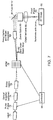
- a system may include a mode locked laser system 70 (e.g., operating at 25 MHz), a pulse picker 72, an optional optical amplifier 74, relay optics 76, a pulse selection unit 78 (e.g., an acousto-optic modulator), a zero order beam stop 80, relay optics and a beam expander 82 a fold mirror 84, zoom optics 86 and an objective lens 88.
- the laser pulses are focused at the focal plane onto a substrate 90 having links that is supported by an XY stage 92.
- the position of the stage 92 is controlled by a controller 94, and the controller 94 also controls the selection of pulses by the pulse picker 72 and/or the pulse selection unit 78.
- the selection of pulses may be done either before or after the optical amplifier, and either or both of the pulse picker 72 and pulse selection unit 78 may be used.
- the system may also include an optional wavelength shifter to change the frequency of the illumination from, for example, 1064 ⁇ m to 532 ⁇ m.
- a link group 30mm in length is processed where links are 3 ⁇ m apart.
- the links are first processed at a constant velocity with a laser repetition rate of 50kHz.
- This trajectory requires a total time of 151.66 ms resulting in a time savings of 48.333 ms or about 24.2%.
- two parallel link groups 9mm in length are separated by 0.1875 mm in the cross-axis and where the on-axis start and end coordinates are the same.
- the links are blasted in opposite on-axis directions at 150mm/s and at -150mm/s; one link group is being blasted and then the substrate/stage is reversing direction, moving 0.1875mm in the cross-axis and blasting the second link group.
- the total time is calculated is 3 parts, the time to blast the first link group, the time to reverse on-axis direction and step 0.1875mm in the cross-axis, and the time to blast the second link group.
- the deceleration is begun 15ms before the end of the link group blasting.
- such laser system in a memory repair system is used to measure the location of a substrate on a stage.
- This operation is referred to as alignment.
- the substrate is moved at a low constant velocity such that a feature on the substrate crosses the focused laser beam spot.
- the laser is fired at a constant repetition rate, the pulses are optically attenuated by the AOM, and directed to the substrate along the laser processing output axis.
- the pulses are attenuated such that the feature on the substrate is not damaged by the laser pulse.
- alignment reflected light from the feature is collected by a detector and a signal is generated. From this collected light signal it is possible to determine the location of the feature on the substrate.
- a similar method is used to determine best focus location.
- the velocity of the stage is typically about 10mm/s.
- the length of a scan is typically about 50 ⁇ m. Often a number of these scans are done serially crossing the same feature on the substrate numerous times in both directions with the stage stopping between operations.
- the time for one of these scan operations using constant velocity methods is the time to accelerate from stopped to 10mm/s, the time for the actual scan, and the time to decelerate to stopped. Typically the acceleration and deceleration times are equal to the minimum acceleration pulse time, assumed here to be 5ms each.
- the constant velocity segment is not required.
- the stage could be accelerated up to 10mm/s in 5ms time (the minimum acceleration pulse time) and then decelerated back to stopped in another 5ms time (the minimum acceleration pulse time).
- the acceleration could be set such that the total move distance is 50 ⁇ m, the scan distance. For this example an acceleration of 4m/s 2 is required.
- the resulting total scan time is 10ms resulting in a time savings of 5ms or about 33%.
- the alignment operation may be a carried our during acceleration, with a low power laser, high speed detector, and data converter.
- the low power laser output axis may be aligned to the laser processing axis.
- the substrate is located on the XY stage with some finite rotation of the link group axis relative to the ideal stage X and Y axes.
- stage motion in both stage axis, X and Y are constant velocity. Because of the small rotation of the stage ideal axis relative to the substrate on-axis and cross-axis directions the stage velocity in the stage ideal coordinate system in one axis will be nearly equal to the on-axis velocity and the stage velocity in the stage ideal coordinate system in the other axis will be close to but not equal to zero.
- stage trajectories when planning stage trajectories using the methods of this invention, it is necessary to consider this small angle between the stage ideal coordinate system and the substrate on-axis/cross-axis coordinate system. If stage trajectories are planned in the substrate on-axis/cross-axis coordinate system then the trajectory can be planned such that the cross-axis velocity is zero at the beginning of a link group to be blasted. If stage trajectories are planned in the stage ideal coordinate system then more care may be required in trajectory planning.
- stage trajectories are planned in the stage ideal coordinate system and the stage axis close to the cross-axis is planned to have a constant velocity motion at the beginning of the link group to be blasted then, if the stage is moving at a non-constant velocity (accelerating or decelerating) in the stage axis close to the on-axis direction a small cross-axis error in blast position may occur.
- Some of the methods include: 1) Plan the trajectories in the substrate on-axis/cross-axis coordinate system. 2) Plan the trajectories in the stage ideal coordinate system and accept a small cross-axis error.
- the present invention does not require that each of the links to be blasted in a group be blasted along a single on-axis line across the group of links. In other words, some off-axis movement across a group of links may be permitted in certain embodiments.
- the system may provide increased maximum positioning velocity. Further, the system may provide increased laser output pulse rates and burst rates. And the system may reduce acceleration forces to reduce attendant mechanical perturbations thereby improving system accuracy.
- the system may be adapted for use with multi-path and multi-spot beam positioning systems.
- Pulsed lasers utilized in various embodiments may include mode locked lasers, high speed laser diodes, or various combinations thereof.
- a GHz repetition rate/rate mode locked semiconductor lasers is disclosed in " Passively Mode-Locked Diode-Pumped Surface-Emitting Semiconductor Laser, IEEE Photonics Technology Letters, vol.12, No.9, September 2000 by S. Hoogland et al., and includes a semiconductor saturable absorber mirror (SESAM) in an output cavity coupled to a semiconductor laser diode.
- SESAM semiconductor saturable absorber mirror
- mode locked lasers of Coherent, Inc. of Santa Clara, California, or of Lumera Laser GmbH of Germany may also be used.
- mode locked laser as disclosed, for example, in U.S. Patents Nos. 4,914,663 and 6,210,401 may also be used.
- link pitch and dimensions may continue to shrink, approaching 1 um pitch with .1-.4 um link widths.
- Link processing systems will produce decreasing spot size to match the trend. For instance, as reported in " Laser Processing of Ultra Fine Pitch Fuse Structures in 65 ⁇ m Node Technology", Society for Equipment and Materials International, SEMICON West 2004 by Joohan Lee, James Cordingley and Joseph J. Griffiths discloses a green laser that produced a spot size as fine as about 0.7 ⁇ m to process fine pitch links.
- the decreasing spot dimensions provide for a potential decrease in the energy of a pulse. For example, if the spot diameter is decreased from about 1.5 ⁇ m to about 1.0 ⁇ m, the total energy in a pulse may be decreased two-fold to achieve a given energy density at the target structure.
- the output of the pulsed laser may be sufficient to process links with minimal gain in the optional amplifier 74, or to possibly operate without the amplifier 74.
- an amplifier may be advantageous, or required. For instance, such a situation may arise if a few pulses are to process the target material.
- An optional optical amplifier may be used to amplify the output of the pulsed laser.
- a mode locked oscillator, high speed diode, or fiber laser oscillator may produce picosecond or femtosecond pulses with about 100 picojoules to a few nanojoules of energy per pulse.
- the amplifier will generally be used to increase the pulse energy to levels suitable for the material processing task, for instance with gain of 6 dB-50 dB.
- the amplifier may be a fiber laser amplifier, waveguide amplifier, or a diode pumped solid state amplifier.
- the amplifier may be CW or pulse pumped. '
- the amplifier performance will generally be limited based on a compromise of several parameters: gain, output repetition rate, and number of pulses (duty cycle) as a result of at least the achievable average power limitations.
- At least one of the shape and energy distribution of a group of output pulses may be altered if the amplifier is pulse pumped or otherwise operated at varied repetition rates. For example, if a pulse picker is used prior to the amplifier the inputs to the amplifier will be spaced at non-uniform temporal intervals, corresponding to a group of pulses are selected for processing. The effective repetition rate will vary, and the resulting effects will be noticeable if the amplifier is operated within a frequency range wherein the output pulse energy varies with the rate.
- a high speed modulator for instance the output modulator 78, may be used to control the pulse shape and energy distribution based on predetermined spacings.
- U.S. Patent No. 5,128,601 teaches the use of a modulator to provide for constant output pulse energy characteristics, as well as other methods for pulse control.
- Other systems such as disclosed for example in U.S. Patents Nos. 5,812,569 and 5,226,051 involve output stabilization, and the principles have been employed for use in q-switched laser systems.
- the pulsed laser is to be operated at a constant rate with pulses selected with the output modulator 78.
- amplification is preferably achieved with the use of a multistage amplifier design, wherein each stage is operated so as to amplify the input pulse train while avoiding distortion, and also with gain low enough such that the amplifier operates well within the average power specification.
- This embodiment is particularly suited for operating at short wavelengths, for instance, green or UV wavelengths, wherein a non-linear crystal performs wavelength shifting.
- One stage of amplification may include a pre-amplifier.
- Cascaded amplifiers 74 may be fiber amplifiers.
- PCT Publication WO98042050 entitled "Pulsed Semiconductor High Power Amplifier and Exemplary Applications", describes many aspects of high power fiber amplifier systems, including multistage amplifiers, and exemplary applications in laser material processing.
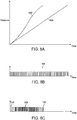
- Figures 8A - 8C compare blasting links using conventional methods and using the methods of this invention.
- Figure 8A shows the distance verses time curves when blasting the same link group using conventional methods 100 and using the methods of an embodiment of the present invention 102.
- the velocity is the same (constant) for the entire link group resulting in a linear constant slope distance verses time curve 100.
- the velocity is not constant during the blasting time.
- the blasting velocity is equal to the blasting velocity of curve 100, in the center of curve 102, however, the blasting velocity has increased resulting is a steeper slope to the distance verses time curve and resulting in an overall decrease in the total blast time.
- the links to be blasted have a constant pitch; the links are equally spaced in distance.
- the blasts for the equally spaced links result in blasts that are equally spaced in time as is shown at 104 in Figure 8B , represent the times for each blast.
- blasting at changing velocity the blasts for the equally spaced links (constant pitch) result in blasts that are unequally spaced in time as is shown in Figure 8C .
- the lines shown at 106 represent the times for each blast at the beginning
- the lines shown at 108 represent the times for each blast in the middle
- the lines shown at 110 represent the times for each blast at the end of a link group.
- the blasts at the beginning of the trajectory 106 and the blasts at the end of the blast trajectory 110 are spaced in time at the same spacing as the blasts using conventional methods because the velocity is the same at these times.
- the blasts at the center of the trajectory 108 are more closely spaced in time but are equally spaced in distance with respect to the blasts when using conventional methods because the velocity at this time is greater. Since the same number of blasts are required when using conventional methods as when using the methods of this invention the same number of blasts are shown in Figures 8B and 8C .
Abstract
Description
- The present invention relates generally to a method of on-the-fly processing of at least one structure of a group of structures according to the preamble of claim 1 (see, for example,
US 2006/119691 A1 ), in particular of integrated circuits on semiconductor wafers, and relates in particular to severing conductive links (e.g., link blowing) on memory integrated circuits. For example, "LIA Handbook of Laser Materials Processing," by J.F. Ready, Laser Institute of America, 2001, discloses general information regarding link blowing at Chapter 19. - When manufactured, memory die typically include some number of defective memory cells due to limitations in semiconductor fabrication technologies. To make memory die with defective memory cells useable, memory die are typically manufactured containing extra memory cells that may be used in place of defective cells. The defective memory cells must then be isolated. Integrated circuit memory repair systems employ a focused laser beam to open (or blast) fusible links on integrated circuit memory die in order to provide that only properly functioning memory cells are coupled to the circuit memory.
- The processing speed of conventional memory repair systems, however, may be limited by the pulse repetition rate of the laser system. As the demands of laser processing systems increase, there is a need for memory repair systems to be faster and more efficient. Efforts to change the pulse rate however, for example by increasing the Q switch rate, result in changes in pulse shape and energy, which may adversely affect memory system repair.
-
- There is a need, therefore, for faster and more efficient memory repair systems.
- A method of on-the-fly processing at least one structure of a group of structures with a pulsed laser output is defined in claim 1.
- In accordance with an embodiment, a mode locked laser is used at pulse rate frequencies from about 10 MHz to about 200 MHz, and in accordance with further embodiments, each link to be blasted may receive a plurality of pulses. In accordance with an embodiment of the invention therefore, it is no longer required to synchronize the substrate/stage velocity with the laser pulse rate to provide that a link to be blasted is positioned at the location of the focused laser beam at the time of a laser pulse.
- The following description may be further understood with reference to the accompanying drawings in which:
-
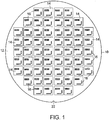
Figure 1 shows an illustrative diagrammatic view of a wafer that may be processed in accordance with an embodiment of the invention that includes a plurality of circuits, each of which has groups of memory links; -
Figure 2 shows an illustrative diagrammatic enlarged view of selected circuits ofFigure 1 showing groups of memory links having identified links that require blasting in accordance with an embodiment of the invention; -
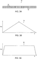
Figures 3A, 3B and 3C show illustrative diagrammatic views of a) a group of links, b) a linear ramped acceleration across the group of links ofFigure 3A with a central peak, and c) a linear ramped acceleration across the group of links ofFigure 3A with an extended constant acceleration peak in accordance with an embodiment of the invention; -
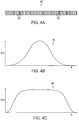
Figures 4A, 4B and 4C show illustrative diagrammatic views of a) a group of links, b) a non-linear ramped acceleration across the group of links ofFigure 4A with a central peak, and c) a non-linear ramped acceleration across the group of links ofFigure 4A with an extended constant acceleration peak in accordance with an embodiment of the invention; -
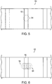
Figure 5 shows an illustrative diagrammatic view of a heat affected zone of a link being blasted with a single pulse in accordance with an embodiment of the invention; -
Figure 6 shows an illustrative diagrammatic view of a plurality of heat affected zones of a link being blasted with multiple pulses in accordance with an embodiment of the invention; -
Figure 7 shows an illustrative diagrammatic view of a laser processing system which can be used in the method according to the present invention; and -
Figures 8A - 8C show illustrative graphical and diagrammatic views of link blasting time charts in a constant velocity system and a non-constant velocity system which can be used in the method according to the present invention. - The drawings are shown for illustrative purposes only.
- The memory cells on a memory die are typically arranged in a matrix of rows and columns of memory cells. Extra memory cells are included on the memory die by increasing the number of rows and/or columns of the memory matrix to include excess rows and columns of memory cells. Defective memory cells in the memory matrix are avoided (not used) by modifying memory matrix addressing to provide matrix rows and columns that are defect free. Fusible links are used to modify memory matrix addressing, and a laser is used to open (or blast) the selected fusible links in a laser memory repair system. Memory die are processed therefore to select only defect free memory cells before the wafer is diced. Typically memory wafers are 200mm or 300mm in diameter.
- The fusible links on memory die are typically arranged in groups of links where each group consists of a row or column of links. Within each row or column the links are generally spaced at equal increments. Link size and spacing vary significantly dependent on the manufacturer and the memory design. Link dimensions for a typical memory design may be for example, 0.4µm wide and 4µm long, with 3µm space between links.
- Further designs may include at least some links having widths of about 0.1 - 0.2 µm, spaced apart at about 1 - 1.5 um. Link processing at the finer scale using a 50 MHz mode locked laser as disclosed, for example, in "Laser Processing of Ultra Fine Pitch Fuse Structures in 65 µm Node Technology", Society for Equipment and Materials International, SEMICON West 2004 by Joohan Lee, James Cordingley and Joseph J. Griffiths shows in
Figure 6 thereof a burst of (amplified) mode locked pulses, at least a portion which was applied to a link has also been achieved in accordance with the invention. - The memory repair system is provided a map of link locations on the memory die and a file listing the links on each die on the wafer that need to be opened (blasted). Typically relatively few links on a circuit are blasted and the locations of the links blasted on each circuit are typically different. The memory repair system opens the links using a pulsed laser beam focused to a desired beam waist.
- The links to be blasted are positioned in the XY plane relative to the focused laser beam axis. For example, the wafer may be carried on a precision XY stage during processing. Other relative positioning devices and systems can be used and combined to structures for processing. These may include split stage positioning systems, multi-rate positioning systems, galvanometer scanners, acousto-optic deflectors, fast steering mirrors, electro-optic deflectors and piezo driven positioners. It is to be understood that although for convenience positioning may be referred in terms of stage motion, the scope of the invention includes other positioning schemes. Laser focus is maintained during link blasting by adjusting laser focus position (beam waist) in the Z axis (vertical axis).
- Prior to link blasting, the position and orientation of the die sites carried on the wafer must be precisely registered with the laser focus position. Alignment may include camera imaging and laser scanning of alignment targets or of other target features. Typically, laser edge scanning is used for fine alignment and the scanning overhead contributes to the overall link processing time.
- When blasting a group of links a laser is fired (pulsed) at approximately a constant repetition rate. Firing the laser at a constant repetition rate helps maintain a precise and constant amount of energy in each laser pulse thereby providing consistent laser energies to each link blasted. The constant rate may result from a laser trigger signal, or may be an inherent property of the laser cavity.
- Conventionally, the stage is moved at a constant velocity during link blasting in order to position successive equally spaced links of a link group at the location of the focused laser beam at the time of the next laser pulse such that each laser pulse corresponds to a single link in a group of links. The constant velocity move used during link blasting is referred to as a CV (constant velocity) move. In accordance with an embodiment of the invention however, it is no longer required to synchronize the substrate/stage velocity with the laser pulse rate to provide that a link to be blasted is positioned at the location of the focused laser beam at the time of a laser pulse.
- Not all links in a group are typically blasted, therefore not all fired laser pulses are used to blast links. A pulse selector (typically an acoustic optic modulator) is used to route pulses either through the focusing lens to the link if the link is to be blasted or to a beam dump if the link is not to be left blasted. An acoustic optic modulator is typically also used to reduce the laser pulse energy to the desired energy for blasting a link.
- Various motion profiles, aspects of path planning, and trajectory generation are disclosed, for example in
U.S. Patents Nos. 6,144,118 ;6,483,071 and6,662,063 , the disclosures of which are hereby incorporated by reference. The teachings of these references may be applied to trajectory planning in systems in accordance with various embodiments of the invention utilizing the split stage positioning systems, multi-rate positioning systems, fast steering mirrors, sold state deflectors, and piezo-electric driven positioners. - After processing a group of links the stage is then moved to the next link group to be blasted. The stage move trajectory for moves between link groups is computed to position the stage at the beginning of the next group with the appropriate velocity for blasting the next group. These non-constant velocity moves between link groups are referred to as PVT (position velocity time) moves. Conventionally, the end point requirements for the move are a position and a velocity at a specified time. The specified time is required in order to coordinate the stage X direction move with the stage Y direction move so that at the end of the move both axis meet the end point requirements at the same time.
- A system controller coordinates all activities during processing. These activities include laser firing, stage/substrate motion, and pulse selection. Typically stage motions are commanded to provide move segments such that the links to be blasted are positioned at the location of the focused laser beam and then laser firing is synchronized to the stage motion. With conventional lasers, laser firing is controlled by a laser trigger signal sent from the system controller to the laser. When the laser receives a trigger signal a laser pulse is generated. The laser pulse generated occurs a small delay time after the trigger signal active edge. The delay time typically varies slightly for each pulse resulting in a small jitter in the laser firing time. The laser typically generates a pulse at the time of the trigger signal by either changing the state of a Q switch or by pulsing a seed laser.
- The laser repetition rate selected is determined by the capabilities of the laser and the characteristics of the memory repair system. Typically, higher laser repetition rates result in greater system throughput. The laser is typically operated at a single repetition rate for all link groups on a wafer. Operating at a single repetition rate simplifies laser pulse energy control as pulse energy control only needs to be calibrated for the single repetition rate.
- Laser pulse energy must be carefully controlled and pulse energies should be matched pulse to pulse for example, to better than 2% RMS. Firing the laser at a constant repetition helps to achieve this matching of pulse energies. This need to carefully control and match laser pulse energies, pulse to pulse, has been a primary reason for moving the stage at a constant velocity when blasting links.
- In accordance with an embodiment of the invention, a very high repetition rate laser, typically in the MHz, is used such as may be provided by a mode locked solid state laser. The laser is not triggered to generate pulses at desired times; rather the laser is free running generating pulses that are not synchronized to stage/link positions. The velocity of the substrate/stage (and therefore the motion of the links) is not synchronized to the laser repetition rate. A predetermined pulse time interval is used to select a laser pulse, or plurality of pulses, from the free running laser to blast a link. This pulse time interval occurs substantially at the optimal time for positioning at the desired link. This interval starts before a pulse is selected, and ends after the last pulse is selected. No pulses are selected outside of the pulse time interval. Note that the laser is not triggered to generate a pulse at a specific time but a laser pulse, or plurality of pulses, is selected that occur at a time close to the optimal laser pulse time. Because the laser repetition rate is high as compared to the velocity of the substrate/stage, the error in link position at the time of the laser pulse is small and acceptable.
- The difference in time of the actual laser pulse to the optimal time for the laser pulse is referred to as pulse time jitter. The maximum amount of pulse time jitter is approximately equal to the time between laser pulses of the free running laser. Because the substrate/stage is moving at a velocity, this pulse time jitter corresponds to position error in blasting. If the motions of the stage are acceptably small during the pulse jitter time then the resulting position errors are acceptable. For example, if the substrate/stage is moving at 150mm/s and the laser free running repetition rate is 50MHz, then the time between laser pulses is 1/(50MHz)=20ns. The substrate/stage motion during 20ns when moving at 150mm/s is (20ns)*(150mm/s) = 3nm. If a link is 0.4µm wide then 3nm corresponds to (3nm/0.4µm)*(100) = 0.75% of the width of the link, which in some cases may be an acceptable motion/position error during link blasting.
- As shown in
Figure 1 , asemiconductor wafer 10 may include on asurface 12 thereof a plurality ofcircuits 14, each of which includes a plurality offusible link groups 16. Eachgroup 16 includes one or more links, and eachgroup 16 of eachcircuit 14 may include one ormore links 18 that have been determined to need to be blasted or opened. - During conventional link blasting, small timing corrections (phase corrections) are made in laser firing time to correct for small stage positioning errors. In accordance with the invention, substrate/stage position errors from the commanded position are compensated for by changing the start of the laser pulse time interval. Laser pulse time however, is not changed by changing the time a laser pulse is generated. Rather, laser pulse time is changed by selecting a different pulse from the free running laser within the laser pulse time interval.
- Because it is not required to use substrate/stage velocity to synchronize the laser pulse rate with the stage/substrate motion, it is not required that the substrate/stage move at a substantially constant velocity during blasting. This provides significant advantages in the movement of the stage and efficiency of the system. In accordance with various embodiments of this invention, the substrate/stage may be accelerating, decelerating, or moving at a substantially constant velocity during blasting. This allows for accelerating and decelerating during blasting of a single link group. As shown in
Figure 2 for example, the substrate or stage may be accelerating during processing of a single group, and then decelerate near the end of the group and either reverse direction along one axis (e.g., the X direction) as shown at A, or may change direction from one axis to another (e.g., from Y to X) as shown at B inFigure 2 . In either case, processing speed is increased by permitting the substrate or stage to be moved at a non-constant velocity during processing of a single group prior to the change in direction as indicated at A or B. Moreover, the ability to process at non-constant velocity also permits groups of circuits that are at the edge of the processing field (stage travel limits) to be processed more slowly at the end of the group near the edge, and then more quickly at the center and other end of the group. - As shown for example in
Figure 3A , agroup 30 ofmemory links 32 may be provided along a single linear direction. As shown inFigure 3B , the acceleration of the substrate or stage may be increasing linearly until the mid-point of the travel along thegroup 30, and then decreasing linearly as shown at 34. As shown inFigure 3C , the acceleration of the substrate or stage may be increasing linearly at a rapid linear rate until it reaches a plateau. The acceleration may then remain constant for an extended period time, and then decrease linearly as the substrate or stage reaches the end of the group shown at 36. More generally, the substrate or stage may be accelerating or decelerating during the blasting of a link group. - As shown in
Figure 4A , agroup 40 ofmemory links 42 may be provided along a single linear direction, and as shown inFigure 4B , the acceleration of the substrate or stage may be increasing non-linearly until the mid-point of the travel along thegroup 40, and then decreasing non-linearly as shown at 44. As shown inFigure 4C , the acceleration of the substrate or stage may be increasing non-linearly at a rapid rate until it reaches a plateau. The acceleration may then remain relatively constant for an extended period time, and then decrease non-linearly as the substrate or stage reaches the end of the group shown at 46. Again, more generally, the substrate or stage may be accelerating or decelerating during the blasting of a link group. - Acceleration may be limited by thermal loading, power, mechanical or other system parameters. For example, high acceleration may produce high motor forces that may introduce unacceptable mechanical vibrations into the system and affect positioning accuracy. Acceleration may be reduced in combination with accelerating during blasting to improve system performance. For example, reduced acceleration may reduce mechanical vibration or other adverse conditions that generally limit usable acceleration and thereby increase system accuracy while maintaining or increasing system throughput. Reduced acceleration may be part of a structured acceleration profile and may be used in conjunction with increased periods of acceleration and with velocities that exceed conventional pulse rate limited synchronization speeds.
- The laser pulse rate may be unsynchronized relative to the stage/substrate motion, and so the commanded stage velocity can be set within a continuous range of velocities. This continuous range of velocities is in contradistinction to conventional systems, where the commanded stage velocity is limited to discrete sets of velocities that are synchronized during blasting based on the laser pulse rate and the regularly spaced link pitch such that the substrate/stage is at a desired location at the time of a laser pulse. This available continuous range of velocities provides added degrees of freedom in trajectory planning that may be used to optimize system throughput.
- Two directions that are generally referred to in connection with stage/substrate trajectories during link blasting are on-axis and cross-axis. The term on-axis refers to the direction along a particular group of links; and this is the direction of stage/substrate motion when blasting the particular link group. The term cross-axis refers to the direction in the XY plane orthogonal to the on-axis direction, which is the direction across the particular link group. The commanded velocity in the cross-axis direction when blasting link groups is zero.
- Methods of various embodiments of the present invention may permit increased system throughput during the blasting of a single link group, as well as processing of each circuit. For a single link group the velocity at the beginning of the link group may be less than the maximum blast velocity, a velocity that allows for a quick transition from a previous link group to the present link group. Then during the blasting of the link group the velocity may be increased (acceleration) to reduce the blast time and then decreased (deceleration) to bring the velocity down to a velocity that allows for a quick transition from the current link group to the next link group. Examples of such transitions are shown at A and B in
Figure 2 . - Methods of certain embodiments of the invention also permit increased throughput by reducing the stage/substrate travel time between link groups that are to be blasted in accordance with certain embodiments. This reduction in time is possible because of a reduction in requirements on the generated trajectory between two link groups. In conventional systems, there are requirements on the end conditions for the trajectory between two link groups and there are constraints on the actual trajectory generated for the trajectory between two link groups. In accordance with various embodiments of this invention, the number of these requirements (constraints) is reduced.
- In particular, in typical conventional systems, there are nine requirements on the end conditions of a trajectory between two link groups. These requirements are the on-axis and cross-axis positions and velocities at the beginning and end of the trajectory (total of 8 requirements) and a time requirement that the end point conditions for both the on-axis and cross-axis move occur at the same time.
- For the methods of certain embodiments of this invention, there are only seven requirements on the end conditions of a trajectory between two link groups. These requirements are the cross-axis positions and velocities at the beginning and end of the trajectory (total of 4 requirements), the on-axis positions at the beginning and end of the trajectory (total of 2 requirements) and a time requirement that the end point conditions for both the on-axis and cross-axis more occur at the same time. There are no longer fixed requirements on the on-axis velocities at the beginning and end of the trajectory, rather there are constraints only on the range of values for on-axis velocities at the beginning and end of the trajectory. Effectively, for the on-axis move between two blast groups, the on-axis trajectory may begin before the blasting trajectory is complete and end after blasting has begun for the next link group. There are of course also a number of constraints for the move between two groups of links. These constraints include maximum/minimum velocity, maximum/minimum acceleration, stage travel range limits, and constraints on profile shape.
- In general, a throughput increase may result for moves between blast groups using the methods of this invention when the time required to position the substrate to the correct off-axis position at zero velocity is less than the time required to position the substrate to the correct on-axis position and desired on-axis blast velocity. For these cases it is often possible to modify the velocities at the end of the previous link group and/or at the beginning of the next link group such that it is possible to make the delay time between link groups equal to the time required for the off-axis move or at least less that the move time of conventional systems.
- Increased throughput may also be provided in certain embodiments when blasting near the stage limits of travel. When blasting a long link group where the on-axis link group end is close to the limits of travel of the stage, it is not typically possible to blast the end of the link group at maximum on-axis velocity using conventional systems and methods. It is not possible because there is not enough distance after the end of the link group before the stage end of travel limit to reduce the stage velocity in the on-axis direction to zero. In order to blast the link group the blast velocity of the entire link group is reduced to a velocity that may be brought to zero velocity in the distance after the end of the link group before the stage end of travel limit. Alternatively, conventional systems may divide a long trajectory near the edge of stage movement of one long link group into two link groups: a long trajectory that is blasted at maximum velocity for the majority of the link group and a short trajectory near the stage travel limits that is blasted at a reduced velocity.
- Using the methods of various embodiments of this invention, the entire link group does not have to be processed at a reduced velocity or broken into two link groups. The blast velocity of the link group may be reduced as the stage travel limit is approached resulting in an overall throughput improvement.
- Increased throughput may also be provided in accordance with various embodiments of the invention by blasting at optimal velocity. In certain conventional systems, only a limited number of synchronized velocities may be used to blast links. The velocities available may not be optimal, for example, if the maximum stage blast velocity is 200mm/s and the maximum blast velocity available to blast a particular link group is 150mm/s. In this case, a sub-optimal velocity must be used for long blast groups. Using the methods of certain embodiments of this invention, the link group may be blasted at the maximum velocity resulting in increased throughput.
- A link blasting system, for example, may have the following constraints on stage motion: Acceleration must be in the range -15m/s2 to +15m/s2; Blast velocity must be in the range -0.2m/s to +0.2m/s, with typical speeds of 50-200 mm/sec.; Acceleration pulse shapes are raised cosine shaped; and Minimum width acceleration pulse is 0.5ms. The raised cosine acceleration pulse shape is generally shown in
Figure 4B and described by the following equation
- The acceleration pulse end point equations for raised cosine acceleration pulses are not unique to raised cosine acceleration pulses profiles. The same acceleration pulse end point equations may result from a number of other acceleration pulse shapes. Two other acceleration pulse profile shapes that result in the same acceleration pulse end point equations are shown in
Figures 3B and 3C . - A laser processing system for use in the method of the invention may include a mode locked laser operating above 20 MHz. The laser may generate pulses at a fixed pulse repetition rate with a fixed phase. As shown at 50 in
Figure 5 , each link to be blown 52 may receive one pulse having a heat affected zone 54. Selecting pulses from a free running pulse train results in increased uncertainty in the actual time that the pulse will be delivered to the target material, which increases pulse time jitter. This increase in pulse time jitter translates into a small increase in positional error when blasting a link if the stage is moving. The corresponding increased pulse time jitter is approximately equal to the time between laser pulses of the free running laser. For example, if a substrate supporting the target material and positioning stage are moving at 150 mm/s and the free running repetition rate is 50 MHz, then the time between laser pulses is 1/50 MHz = 20 ns. The substrate/stage motion during 20 ns when moving at 150 mm/s is 3 nm. If a link is 0.4 µm wide, then 3 nm corresponds to 0.75% of the width of the link, an acceptable positional error during link processing. In accordance with further embodiments, and as shown at 60 inFigure 6 , each link to be blown 62 may receive a plurality of pulses providing a plurality of heat affectedzones 64 across thelink 62. - The laser processing system may be as disclosed, for example, in U.S. Published Patent Application No. 2006-0191884 filed January 18, 2006. For example and with reference to
Figure 7 , a system may include a mode locked laser system 70 (e.g., operating at 25 MHz), apulse picker 72, an optionaloptical amplifier 74,relay optics 76, a pulse selection unit 78 (e.g., an acousto-optic modulator), a zero order beam stop 80, relay optics and a beam expander 82 afold mirror 84,zoom optics 86 and anobjective lens 88. The laser pulses are focused at the focal plane onto asubstrate 90 having links that is supported by anXY stage 92. The position of thestage 92 is controlled by acontroller 94, and thecontroller 94 also controls the selection of pulses by thepulse picker 72 and/or thepulse selection unit 78. The selection of pulses may be done either before or after the optical amplifier, and either or both of thepulse picker 72 andpulse selection unit 78 may be used. The system may also include an optional wavelength shifter to change the frequency of the illumination from, for example, 1064 µm to 532 µm. - The throughput advantages of methods of the invention may be shown by the following examples. In a first example, a link group 30mm in length is processed where links are 3µm apart. As a comparison, the links are first processed at a constant velocity with a laser repetition rate of 50kHz. The substrate/stage velocity during blasting is (3µm)(50kHz) = 150mm/s. The time to blast the link group is (30mm)/(150mm/s) = 200ms. In accordance with an embodiment of the invention, however, it is possible to begin blasting the link group at a velocity of 150mm/s, to accelerate up to 200mm/s during the blasting, and then to decelerate back down to 150mm/s such that the end velocity is 150mm/s. This trajectory requires a total time of 151.66 ms resulting in a time savings of 48.333 ms or about 24.2%.
- In another example, two parallel link groups 9mm in length are separated by 0.1875 mm in the cross-axis and where the on-axis start and end coordinates are the same. The links are blasted in opposite on-axis directions at 150mm/s and at -150mm/s; one link group is being blasted and then the substrate/stage is reversing direction, moving 0.1875mm in the cross-axis and blasting the second link group. For a constant velocity trajectory, the total time is calculated is 3 parts, the time to blast the first link group, the time to reverse on-axis direction and step 0.1875mm in the cross-axis, and the time to blast the second link group. The time to blast each link group is (9mm)/(150mm/s) = 60ms. The time to reverse on-axis direction is 40ms, the time to step in the cross-axis by 0.1875mm is 10ms. Since the time to reverse on-axis direction is greater than the time to step in the cross-axis this is effectively the time required for the turn around. Therefore the total time to process the two link groups is about (60ms)+(40ms)+(60ms) = 160ms. Using the methods of certain embodiments of this invention it is possible to begin the turn around in the on-axis direction before the blasting is complete. In this example, the deceleration is begun 15ms before the end of the link group blasting. Then the total time to process the two link groups is (60ms-15ms)+(40ms)+(60ms-15ms) = 130ms resulting in a time savings of 30ms or about 19%. This trajectory also requires less total stage travel, therefore, this example also shows how total stage travel can be reduced near the stage travel limits.
- In a third example, such laser system in a memory repair system is used to measure the location of a substrate on a stage. This operation is referred to as alignment. During an alignment operation the substrate is moved at a low constant velocity such that a feature on the substrate crosses the focused laser beam spot. I accordance with an embodiment, the laser is fired at a constant repetition rate, the pulses are optically attenuated by the AOM, and directed to the substrate along the laser processing output axis. The pulses are attenuated such that the feature on the substrate is not damaged by the laser pulse. During alignment reflected light from the feature is collected by a detector and a signal is generated. From this collected light signal it is possible to determine the location of the feature on the substrate. A similar method is used to determine best focus location. During these operations the velocity of the stage is typically about 10mm/s. The length of a scan is typically about 50µm. Often a number of these scans are done serially crossing the same feature on the substrate numerous times in both directions with the stage stopping between operations. The time for one of these scan operations using constant velocity methods is the time to accelerate from stopped to 10mm/s, the time for the actual scan, and the time to decelerate to stopped. Typically the acceleration and deceleration times are equal to the minimum acceleration pulse time, assumed here to be 5ms each. The time to scan is equal to (50µm)/(10mm/s) = 5ms. The total scan time, therefore, is 15ms. Using the methods of certain embodiments of the invention, the constant velocity segment is not required. The stage could be accelerated up to 10mm/s in 5ms time (the minimum acceleration pulse time) and then decelerated back to stopped in another 5ms time (the minimum acceleration pulse time). The acceleration could be set such that the total move distance is 50µm, the scan distance. For this example an acceleration of 4m/s2 is required. The resulting total scan time is 10ms resulting in a time savings of 5ms or about 33%.
- In accordance with another embodiment, the alignment operation may be a carried our during acceleration, with a low power laser, high speed detector, and data converter. The low power laser output axis may be aligned to the laser processing axis.
- Typically the substrate is located on the XY stage with some finite rotation of the link group axis relative to the ideal stage X and Y axes. When blasting link groups therefore, there is typically a non-zero stage velocity in both the X & Y stage axis. During link blasting in conventional constant velocity systems, the stage motion in both stage axis, X and Y, are constant velocity. Because of the small rotation of the stage ideal axis relative to the substrate on-axis and cross-axis directions the stage velocity in the stage ideal coordinate system in one axis will be nearly equal to the on-axis velocity and the stage velocity in the stage ideal coordinate system in the other axis will be close to but not equal to zero. Therefore, when planning stage trajectories using the methods of this invention, it is necessary to consider this small angle between the stage ideal coordinate system and the substrate on-axis/cross-axis coordinate system. If stage trajectories are planned in the substrate on-axis/cross-axis coordinate system then the trajectory can be planned such that the cross-axis velocity is zero at the beginning of a link group to be blasted. If stage trajectories are planned in the stage ideal coordinate system then more care may be required in trajectory planning. If stage trajectories are planned in the stage ideal coordinate system and the stage axis close to the cross-axis is planned to have a constant velocity motion at the beginning of the link group to be blasted then, if the stage is moving at a non-constant velocity (accelerating or decelerating) in the stage axis close to the on-axis direction a small cross-axis error in blast position may occur. There are a number of methods to handle this possible cross-axis error. Some of the methods include: 1) Plan the trajectories in the substrate on-axis/cross-axis coordinate system. 2) Plan the trajectories in the stage ideal coordinate system and accept a small cross-axis error. Larger cross-axis errors are acceptable in link blasting because links are typically long in the cross-axis direction. 3) Put a small rotation into the XY stage to make the XY stage ideal coordinate system be the same as the substrate on-axis/cross-axis coordinate system. 4) Plan a non-constant velocity during blasting in the stage ideal coordinate axis that is close to the substrate cross-axis direction.
- In accordance with further embodiments, the present invention does not require that each of the links to be blasted in a group be blasted along a single on-axis line across the group of links. In other words, some off-axis movement across a group of links may be permitted in certain embodiments.
- Such system does not required that the links be evenly spaced. The system may provide increased maximum positioning velocity. Further, the system may provide increased laser output pulse rates and burst rates. And the system may reduce acceleration forces to reduce attendant mechanical perturbations thereby improving system accuracy. The system may be adapted for use with multi-path and multi-spot beam positioning systems.
- Pulsed lasers utilized in various embodiments may include mode locked lasers, high speed laser diodes, or various combinations thereof. For example, a GHz repetition rate/rate mode locked semiconductor lasers is disclosed in "Passively Mode-Locked Diode-Pumped Surface-Emitting Semiconductor Laser, IEEE Photonics Technology Letters, vol.12, No.9, September 2000 by S. Hoogland et al., and includes a semiconductor saturable absorber mirror (SESAM) in an output cavity coupled to a semiconductor laser diode. In accordance with other embodiments, mode locked lasers of Coherent, Inc. of Santa Clara, California, or of Lumera Laser GmbH of Germany may also be used. In accordance with further embodiments, mode locked laser as disclosed, for example, in
U.S. Patents Nos. 4,914,663 and6,210,401 may also be used. - As previously noted, link pitch and dimensions may continue to shrink, approaching 1 um pitch with .1-.4 um link widths. Link processing systems will produce decreasing spot size to match the trend. For instance, as reported in "Laser Processing of Ultra Fine Pitch Fuse Structures in 65 µm Node Technology", Society for Equipment and Materials International, SEMICON West 2004 by Joohan Lee, James Cordingley and Joseph J. Griffiths discloses a green laser that produced a spot size as fine as about 0.7 µm to process fine pitch links. The decreasing spot dimensions provide for a potential decrease in the energy of a pulse. For example, if the spot diameter is decreased from about 1.5 µm to about 1.0 µm, the total energy in a pulse may be decreased two-fold to achieve a given energy density at the target structure. Further, in some embodiments it may be advantageous to increase the number of pulses applied to a link, and to proportionately decrease the pulse energy, for example. In such embodiments the output of the pulsed laser may be sufficient to process links with minimal gain in the
optional amplifier 74, or to possibly operate without theamplifier 74. In some embodiments an amplifier may be advantageous, or required. For instance, such a situation may arise if a few pulses are to process the target material. - An optional optical amplifier may be used to amplify the output of the pulsed laser. For example, a mode locked oscillator, high speed diode, or fiber laser oscillator may produce picosecond or femtosecond pulses with about 100 picojoules to a few nanojoules of energy per pulse. The amplifier will generally be used to increase the pulse energy to levels suitable for the material processing task, for instance with gain of 6 dB-50 dB. The amplifier may be a fiber laser amplifier, waveguide amplifier, or a diode pumped solid state amplifier. The amplifier may be CW or pulse pumped. '
- The amplifier performance will generally be limited based on a compromise of several parameters: gain, output repetition rate, and number of pulses (duty cycle) as a result of at least the achievable average power limitations.
- At least one of the shape and energy distribution of a group of output pulses may be altered if the amplifier is pulse pumped or otherwise operated at varied repetition rates. For example, if a pulse picker is used prior to the amplifier the inputs to the amplifier will be spaced at non-uniform temporal intervals, corresponding to a group of pulses are selected for processing. The effective repetition rate will vary, and the resulting effects will be noticeable if the amplifier is operated within a frequency range wherein the output pulse energy varies with the rate.
- In some embodiments a high speed modulator, for instance the
output modulator 78, may be used to control the pulse shape and energy distribution based on predetermined spacings. For example,U.S. Patent No. 5,128,601 , teaches the use of a modulator to provide for constant output pulse energy characteristics, as well as other methods for pulse control. Other systems, such as disclosed for example inU.S. Patents Nos. 5,812,569 and5,226,051 involve output stabilization, and the principles have been employed for use in q-switched laser systems. - In some preferred embodiments of the present invention the pulsed laser is to be operated at a constant rate with pulses selected with the
output modulator 78. In such cases amplification is preferably achieved with the use of a multistage amplifier design, wherein each stage is operated so as to amplify the input pulse train while avoiding distortion, and also with gain low enough such that the amplifier operates well within the average power specification. This embodiment is particularly suited for operating at short wavelengths, for instance, green or UV wavelengths, wherein a non-linear crystal performs wavelength shifting. One stage of amplification may include a pre-amplifier.Cascaded amplifiers 74 may be fiber amplifiers.PCT Publication WO98042050 -
Figures 8A - 8C compare blasting links using conventional methods and using the methods of this invention.Figure 8A shows the distance verses time curves when blasting the same link group usingconventional methods 100 and using the methods of an embodiment of thepresent invention 102. When blasting using conventional methods the velocity is the same (constant) for the entire link group resulting in a linear constant slope distanceverses time curve 100. When blasting using the methods of this invention the velocity is not constant during the blasting time. In the example shown inFigure 8A , at the beginning and end ofcurve 102 the blasting velocity is equal to the blasting velocity ofcurve 100, in the center ofcurve 102, however, the blasting velocity has increased resulting is a steeper slope to the distance verses time curve and resulting in an overall decrease in the total blast time. - In this example the links to be blasted have a constant pitch; the links are equally spaced in distance. When using conventional methods blasting at a constant velocity the blasts for the equally spaced links result in blasts that are equally spaced in time as is shown at 104 in
Figure 8B , represent the times for each blast. When using the methods of this invention blasting at changing velocity the blasts for the equally spaced links (constant pitch) result in blasts that are unequally spaced in time as is shown inFigure 8C . In particular, the lines shown at 106 represent the times for each blast at the beginning, the lines shown at 108 represent the times for each blast in the middle, and the lines shown at 110 represent the times for each blast at the end of a link group. For this example the blasts at the beginning of the trajectory 106 and the blasts at the end of theblast trajectory 110 are spaced in time at the same spacing as the blasts using conventional methods because the velocity is the same at these times. The blasts at the center of thetrajectory 108 are more closely spaced in time but are equally spaced in distance with respect to the blasts when using conventional methods because the velocity at this time is greater. Since the same number of blasts are required when using conventional methods as when using the methods of this invention the same number of blasts are shown inFigures 8B and 8C . - Those skilled in the art will appreciate that numerous modifications and variations may be made to the above disclosed embodiments without departing from the scope of the invention as defined in the appended claims.
Claims (15)
- A method of on-the-fly processing at least one structure (18, 52, 62) of a group of structures (16, 30, 40) with a pulsed laser output (104, 106. 108, 110), said method comprising the steps of:relatively positioning the group of structures (16, 30, 40) and the pulsed laser output axis; andapplying the pulsed laser output (104, 106, 108, 110) to the at least one structure of the group of structures during the step of relatively positioning the group of structures and the pulsed laser output axis, said method being characterized in thatthe step of relatively positioning the group of structures (16, 30, 40) and the pulsed laser output axis occurs at a non-constant velocity; andthe step of applying the pulsed laser output (104, 106, 108, 110) to the at least one structure of the group of structures includes providing the pulsed laser output by selecting one or more laser pulses from a laser (70) that is pulsed at a constant rate such that laser processing may be performed without laser triggering being based on the position or velocity of a moving stage;wherein the pulsed laser output is provided by selecting pulses of a constant pulse rate laser during time intervals, each time interval corresponding to a position of at least one structure to be processed, andthe position of the stage is controlled by a controller (94), and the controller also controls the selection of pulses by a pulse picker (72) and/or a pulse selection unit (78), wherein the selection of pulses may be done either before or after an optical amplifier, such that position of the at least one structure during a pulse is within an acceptable position error.
- The method as claimed in Claim 1, wherein the pulsed laser output is provided by selecting pulses of a mode locked laser during time intervals, each time interval corresponding to a position of at least one structure to be processed.
- The method as claimed in Claim 1 or Claim 2, wherein the non-constant velocity is provided by accelerating or decelerating.
- The method as claimed in any preceding claim, wherein the non-constant velocity is provided by decelerating along a current direction of movement (X) prior to relatively positioning the group of structures either in direction (Y) transverse to a current direction of movement (X) or in a direction (-X) that is a reverse direction of a current direction of movement (X).
- The method as claimed in any of the preceding claims, wherein the group of structures includes at least a portion of a row of links (18) or a portion of a column of links (18) of a semiconductor device.
- The method as claimed in Claim 5, wherein a plurality of pulses are provided to a structure to process a single link.
- The method as claimed in Claim 5, wherein the links are provided in a plurality of groups of links, and the method includes relatively positioning along each row or column of links and accelerating or decelerating along at least one row or column, respectively, of links.
- The method as claimed in Claim 7, wherein the method involves either (a) accelerating away from, or (b) decelerating towards, an end of a group of links or (c) decelerating toward an end of a group of links and accelerating away from the end of the group of links.
- The method as claimed in any of the preceding claims, wherein said step of applying the pulsed laser output to the at least one structure includes forming a spot from the pulsed laser output in the structure while the movement of one of the group of structures and the pulsed laser output axis is accelerating or decelerating.
- The method as claimed in any of the preceding claims, wherein the constant pulse rate is sufficiently rapid to allow at least one selected pulse to impinge each structure in the group.
- The method as claimed in any of the preceding claims, wherein selected pulses are selected at a time close to the optimal time for positioning laser output at the at least one structure.
- The method as claimed in any of the preceding claims, wherein the laser output impinges the structure with less than a predetermined position error.
- The method as claimed in any of the preceding claims, wherein a difference between each selected pulse time and an optimal pulse time is less than a predetermined timing threshold.
- The method as claimed in any of the preceding claims, wherein the constant pulse repetition rate is an inherent property of the laser.
- The method as claimed in any of the preceding claims, wherein the constant pulse repetition rate results from a laser trigger signal that is not synchronized relative to the positioning of the group of structures.
Applications Claiming Priority (3)
| Application Number | Priority Date | Filing Date | Title |
|---|---|---|---|
| US83208206P | 2006-07-20 | 2006-07-20 | |
| US11/532,160 US8084706B2 (en) | 2006-07-20 | 2006-09-15 | System and method for laser processing at non-constant velocities |
| PCT/US2007/072432 WO2008011255A2 (en) | 2006-07-20 | 2007-06-29 | Systems and methods for laser processing during periods having non-constant velocities |
Publications (2)
| Publication Number | Publication Date |
|---|---|
| EP2043809A2 EP2043809A2 (en) | 2009-04-08 |
| EP2043809B1 true EP2043809B1 (en) | 2012-05-02 |
Family
ID=38805776
Family Applications (1)
| Application Number | Title | Priority Date | Filing Date |
|---|---|---|---|
| EP07840316A Not-in-force EP2043809B1 (en) | 2006-07-20 | 2007-06-29 | Method of on-the-fly laser processing at non-constant velocities |
Country Status (7)
| Country | Link |
|---|---|
| US (2) | US8084706B2 (en) |
| EP (1) | EP2043809B1 (en) |
| JP (1) | JP2009544470A (en) |
| KR (1) | KR20090045260A (en) |
| AT (1) | ATE555868T1 (en) |
| TW (1) | TW200807636A (en) |
| WO (1) | WO2008011255A2 (en) |
Families Citing this family (26)
| Publication number | Priority date | Publication date | Assignee | Title |
|---|---|---|---|---|
| US9029731B2 (en) * | 2007-01-26 | 2015-05-12 | Electro Scientific Industries, Inc. | Methods and systems for laser processing continuously moving sheet material |
| US7982160B2 (en) * | 2008-03-31 | 2011-07-19 | Electro Scientific Industries, Inc. | Photonic clock stabilized laser comb processing |
| RU2529136C2 (en) * | 2008-11-21 | 2014-09-27 | Прецитек Кг | Method and device for control over laser processing of part and laser processing head with above described device |
| JP4612733B2 (en) * | 2008-12-24 | 2011-01-12 | 東芝機械株式会社 | Pulse laser processing equipment |
| WO2010131687A1 (en) * | 2009-05-12 | 2010-11-18 | オリンパスメディカルシステムズ株式会社 | Subject in-vivo imaging system and subject in-vivo introducing device |
| DE102009023307A1 (en) * | 2009-05-29 | 2010-12-02 | Kuka Roboter Gmbh | Method and device for controlling a manipulator |
| JP5620669B2 (en) * | 2009-10-26 | 2014-11-05 | 東芝機械株式会社 | Laser dicing method and laser dicing apparatus |
| US20110210105A1 (en) * | 2009-12-30 | 2011-09-01 | Gsi Group Corporation | Link processing with high speed beam deflection |
| JP5452247B2 (en) * | 2010-01-21 | 2014-03-26 | 東芝機械株式会社 | Laser dicing equipment |
| JP5981094B2 (en) | 2010-06-24 | 2016-08-31 | 東芝機械株式会社 | Dicing method |
| WO2012116226A2 (en) * | 2011-02-25 | 2012-08-30 | Gsi Group Corporation | Predictive link processing |
| WO2013006691A2 (en) | 2011-07-05 | 2013-01-10 | Gsi Group Corporation | Systems and methods for providing temperature stability of acousto-optic beam deflectors and acousto-optic modulators during use |
| JP5140198B1 (en) | 2011-07-27 | 2013-02-06 | 東芝機械株式会社 | Laser dicing method |
| US8976343B2 (en) * | 2012-06-21 | 2015-03-10 | Kla-Tencor Corporation | Laser crystal degradation compensation |
| JP2014011358A (en) | 2012-06-29 | 2014-01-20 | Toshiba Mach Co Ltd | Laser dicing method |
| WO2014145305A1 (en) * | 2013-03-15 | 2014-09-18 | Electro Scientific Industries, Inc. | Laser emission-based control of beam positioner |
| EP2973896B1 (en) * | 2013-03-15 | 2019-09-18 | Electro Scientific Industries, Inc. | Phased array steering for laser beam positioning systems |
| TWI632013B (en) * | 2013-03-15 | 2018-08-11 | 美商伊雷克托科學工業股份有限公司 | Laser processing apparatus to process features on or within a workpiece and methods for laser processing a workpiece |
| TWI637803B (en) | 2013-03-15 | 2018-10-11 | 美商伊雷克托科學工業股份有限公司 | Laser processing apparatus and method for processing a workpiece by operation of a laser tool |
| JP6362130B2 (en) * | 2013-04-26 | 2018-07-25 | ビアメカニクス株式会社 | Laser processing method and laser processing apparatus |
| US10405278B2 (en) * | 2014-10-31 | 2019-09-03 | Qualcomm Incorporated | Low power scheduling |
| TWI582559B (en) * | 2015-01-29 | 2017-05-11 | 國立臺灣大學 | Trajectory planning system for integrated computer numerical control (cnc) machine, trajectory planning device, trajectory planning method, and computer program product thereof |
| CN107405724B (en) | 2015-02-27 | 2020-05-05 | 伊雷克托科学工业股份有限公司 | Fast beam steering for transverse-axis micromachining |
| US20180207748A1 (en) * | 2017-01-23 | 2018-07-26 | Lumentum Operations Llc | Machining processes using a random trigger feature for an ultrashort pulse laser |
| EP3589998B1 (en) | 2017-03-03 | 2023-08-23 | Apton Biosystems, Inc. | High speed scanning system with acceleration tracking |
| CN116425409B (en) * | 2023-04-14 | 2024-03-26 | 深圳市东赢激光设备有限公司 | Laser-based large-size hole opening method, system and medium |
Family Cites Families (111)
| Publication number | Priority date | Publication date | Assignee | Title |
|---|---|---|---|---|
| US4114018A (en) | 1976-09-30 | 1978-09-12 | Lasag Ag | Method for ablating metal workpieces with laser radiation |
| US4483005A (en) | 1981-09-24 | 1984-11-13 | Teradyne, Inc. | Affecting laser beam pulse width |
| US4532402A (en) | 1983-09-02 | 1985-07-30 | Xrl, Inc. | Method and apparatus for positioning a focused beam on an integrated circuit |
| US4555610A (en) | 1983-09-13 | 1985-11-26 | Data Card Corporation | Laser machining system |
| US4829219A (en) | 1986-11-20 | 1989-05-09 | Unimation Inc. | Multiaxis robot having improved motion control through variable acceleration/deceleration profiling |
| US5808887A (en) | 1987-11-20 | 1998-09-15 | Philips Electronics North America Corporation | Animation of path planning |
| US4914663A (en) | 1988-04-22 | 1990-04-03 | The Board Of Trustees Of Leland Stanford, Jr. University | Generation of short high peak power pulses from an injection mode-locked Q-switched laser oscillator |
| US5059764A (en) | 1988-10-31 | 1991-10-22 | Spectra-Physics, Inc. | Diode-pumped, solid state laser-based workstation for precision materials processing and machining |
| IL91240A (en) | 1989-08-07 | 1994-07-31 | Quick Tech Ltd | Pulsed laser apparatus and systems and techniques for its operation |
| US5057664A (en) | 1989-10-20 | 1991-10-15 | Electro Scientific Industries, Inc. | Method and apparatus for laser processing a target material to provide a uniformly smooth, continuous trim profile |
| JP3150322B2 (en) | 1990-05-18 | 2001-03-26 | 株式会社日立製作所 | Wiring cutting method by laser and laser processing device |
| PL169904B1 (en) | 1991-01-17 | 1996-09-30 | United Distillers Plc | Method of and apparatus for marking moving products |
| US5268911A (en) | 1991-07-10 | 1993-12-07 | Young Eddie H | X-cut crystal quartz acousto-optic modulator |
| EP0523270A1 (en) | 1991-07-18 | 1993-01-20 | International Business Machines Corporation | Method to control a positioning system |
| US5293025A (en) | 1991-08-01 | 1994-03-08 | E. I. Du Pont De Nemours And Company | Method for forming vias in multilayer circuits |
| US5280491A (en) | 1991-08-02 | 1994-01-18 | Lai Shui T | Two dimensional scan amplifier laser |
| US5300756A (en) | 1991-10-22 | 1994-04-05 | General Scanning, Inc. | Method for severing integrated-circuit connection paths by a phase-plate-adjusted laser beam |
| DE69232640T2 (en) | 1991-11-06 | 2003-02-06 | Shui T Lai | DEVICE FOR CORNEAL SURGERY |
| DE4229399C2 (en) | 1992-09-03 | 1999-05-27 | Deutsch Zentr Luft & Raumfahrt | Method and device for producing a functional structure of a semiconductor component |
| US5265114C1 (en) | 1992-09-10 | 2001-08-21 | Electro Scient Ind Inc | System and method for selectively laser processing a target structure of one or more materials of a multimaterial multilayer device |
| US5520679A (en) | 1992-12-03 | 1996-05-28 | Lasersight, Inc. | Ophthalmic surgery method using non-contact scanning laser |
| US5374590A (en) | 1993-04-28 | 1994-12-20 | International Business Machines Corporation | Fabrication and laser deletion of microfuses |
| US5453594A (en) | 1993-10-06 | 1995-09-26 | Electro Scientific Industries, Inc. | Radiation beam position and emission coordination system |
| US5611946A (en) | 1994-02-18 | 1997-03-18 | New Wave Research | Multi-wavelength laser system, probe station and laser cutter system using the same |
| JPH09510320A (en) | 1994-03-10 | 1997-10-14 | マサチユセツツ・インスチチユート・オブ・テクノロジー | Method of manufacturing conductive link for connection |
| US5400350A (en) | 1994-03-31 | 1995-03-21 | Imra America, Inc. | Method and apparatus for generating high energy ultrashort pulses |
| JPH0817985A (en) * | 1994-06-27 | 1996-01-19 | Raitetsuku Kk | Laser removal device for tie bar of integrated circuit lead frame |
| US5841099A (en) | 1994-07-18 | 1998-11-24 | Electro Scientific Industries, Inc. | Method employing UV laser pulses of varied energy density to form depthwise self-limiting blind vias in multilayered targets |
| US5539764A (en) | 1994-08-24 | 1996-07-23 | Jamar Technologies Co. | Laser generated X-ray source |
| US5742634A (en) | 1994-08-24 | 1998-04-21 | Imar Technology Co. | Picosecond laser |
| US5790574A (en) | 1994-08-24 | 1998-08-04 | Imar Technology Company | Low cost, high average power, high brightness solid state laser |
| US5662822A (en) | 1994-10-13 | 1997-09-02 | Hitachi Construction Machinery Co., Ltd. | Dam bar cutting apparatus and dam bar cutting method |
| US5685995A (en) | 1994-11-22 | 1997-11-11 | Electro Scientific Industries, Inc. | Method for laser functional trimming of films and devices |
| US5751585A (en) | 1995-03-20 | 1998-05-12 | Electro Scientific Industries, Inc. | High speed, high accuracy multi-stage tool positioning system |
| US5847960A (en) | 1995-03-20 | 1998-12-08 | Electro Scientific Industries, Inc. | Multi-tool positioning system |
| US5786560A (en) | 1995-03-31 | 1998-07-28 | Panasonic Technologies, Inc. | 3-dimensional micromachining with femtosecond laser pulses |
| US5696778A (en) | 1995-05-09 | 1997-12-09 | Ophir Corporation | Method of and apparatus for generating intracavity double raman shifted laser pulses |
| US6150630A (en) | 1996-01-11 | 2000-11-21 | The Regents Of The University Of California | Laser machining of explosives |
| US5720894A (en) | 1996-01-11 | 1998-02-24 | The Regents Of The University Of California | Ultrashort pulse high repetition rate laser system for biological tissue processing |
| US5867305A (en) | 1996-01-19 | 1999-02-02 | Sdl, Inc. | Optical amplifier with high energy levels systems providing high peak powers |
| US5759428A (en) | 1996-03-15 | 1998-06-02 | International Business Machines Corporation | Method of laser cutting a metal line on an MR head |
| US5609779A (en) | 1996-05-15 | 1997-03-11 | General Electric Company | Laser drilling of non-circular apertures |
| US5837962A (en) | 1996-07-15 | 1998-11-17 | Overbeck; James W. | Faster laser marker employing acousto-optic deflection |
| US5998759A (en) | 1996-12-24 | 1999-12-07 | General Scanning, Inc. | Laser processing |
| US6025256A (en) | 1997-01-06 | 2000-02-15 | Electro Scientific Industries, Inc. | Laser based method and system for integrated circuit repair or reconfiguration |
| US6151338A (en) | 1997-02-19 | 2000-11-21 | Sdl, Inc. | High power laser optical amplifier system |
| US5812569A (en) | 1997-03-21 | 1998-09-22 | Lumonics, Inc. | Stabilization of the output energy of a pulsed solid state laser |
| US6156030A (en) | 1997-06-04 | 2000-12-05 | Y-Beam Technologies, Inc. | Method and apparatus for high precision variable rate material removal and modification |
| JP2000210782A (en) | 1998-02-19 | 2000-08-02 | Ricoh Microelectronics Co Ltd | Machining method and its device |
| JP3052928B2 (en) | 1998-04-01 | 2000-06-19 | 日本電気株式会社 | Laser processing equipment |
| US6268586B1 (en) | 1998-04-30 | 2001-07-31 | The Regents Of The University Of California | Method and apparatus for improving the quality and efficiency of ultrashort-pulse laser machining |
| US6057180A (en) | 1998-06-05 | 2000-05-02 | Electro Scientific Industries, Inc. | Method of severing electrically conductive links with ultraviolet laser output |
| US6339604B1 (en) | 1998-06-12 | 2002-01-15 | General Scanning, Inc. | Pulse control in laser systems |
| US6987786B2 (en) | 1998-07-02 | 2006-01-17 | Gsi Group Corporation | Controlling laser polarization |
| US6181728B1 (en) | 1998-07-02 | 2001-01-30 | General Scanning, Inc. | Controlling laser polarization |
| GB9819338D0 (en) | 1998-09-04 | 1998-10-28 | Philips Electronics Nv | Laser crystallisation of thin films |
| US6144118A (en) | 1998-09-18 | 2000-11-07 | General Scanning, Inc. | High-speed precision positioning apparatus |
| US6300590B1 (en) | 1998-12-16 | 2001-10-09 | General Scanning, Inc. | Laser processing |
| US6324195B1 (en) | 1999-01-13 | 2001-11-27 | Kaneka Corporation | Laser processing of a thin film |
| US6172325B1 (en) | 1999-02-10 | 2001-01-09 | Electro Scientific Industries, Inc. | Laser processing power output stabilization apparatus and method employing processing position feedback |
| US6252195B1 (en) | 1999-04-26 | 2001-06-26 | Ethicon, Inc. | Method of forming blind holes in surgical needles using a diode pumped Nd-YAG laser |
| US6341029B1 (en) | 1999-04-27 | 2002-01-22 | Gsi Lumonics, Inc. | Method and apparatus for shaping a laser-beam intensity profile by dithering |
| US6285002B1 (en) | 1999-05-10 | 2001-09-04 | Bryan Kok Ann Ngoi | Three dimensional micro machining with a modulated ultra-short laser pulse |
| TW482705B (en) | 1999-05-28 | 2002-04-11 | Electro Scient Ind Inc | Beam shaping and projection imaging with solid state UV Gaussian beam to form blind vias |
| US6216058B1 (en) | 1999-05-28 | 2001-04-10 | Brooks Automation, Inc. | System of trajectory planning for robotic manipulators based on pre-defined time-optimum trajectory shapes |
| US6472295B1 (en) | 1999-08-27 | 2002-10-29 | Jmar Research, Inc. | Method and apparatus for laser ablation of a target material |
| WO2001020651A1 (en) | 1999-09-10 | 2001-03-22 | Nikon Corporation | Exposure device with laser device |
| JP4517271B2 (en) | 1999-09-10 | 2010-08-04 | 株式会社ニコン | Exposure apparatus equipped with a laser device |
| US6340806B1 (en) | 1999-12-28 | 2002-01-22 | General Scanning Inc. | Energy-efficient method and system for processing target material using an amplified, wavelength-shifted pulse train |
| US7723642B2 (en) * | 1999-12-28 | 2010-05-25 | Gsi Group Corporation | Laser-based system for memory link processing with picosecond lasers |
| US6281471B1 (en) | 1999-12-28 | 2001-08-28 | Gsi Lumonics, Inc. | Energy-efficient, laser-based method and system for processing target material |
| US20030222324A1 (en) | 2000-01-10 | 2003-12-04 | Yunlong Sun | Laser systems for passivation or link processing with a set of laser pulses |
| KR100830128B1 (en) | 2000-01-10 | 2008-05-20 | 일렉트로 싸이언티픽 인더스트리이즈 인코포레이티드 | Laser system and method for processing a memory link with a burst of laser pulses having ultrashort pulse widths |
| US7671295B2 (en) | 2000-01-10 | 2010-03-02 | Electro Scientific Industries, Inc. | Processing a memory link with a set of at least two laser pulses |
| US6887804B2 (en) | 2000-01-10 | 2005-05-03 | Electro Scientific Industries, Inc. | Passivation processing over a memory link |
| DE60114397T2 (en) * | 2000-01-11 | 2006-08-03 | Electro Scientific Industries, Inc., Portland | METHOD AND DEVICE FOR CORRECTING ABBE ERRORS |
| US6552301B2 (en) | 2000-01-25 | 2003-04-22 | Peter R. Herman | Burst-ultrafast laser machining method |
| US6541731B2 (en) | 2000-01-25 | 2003-04-01 | Aculight Corporation | Use of multiple laser sources for rapid, flexible machining and production of vias in multi-layered substrates |
| WO2001074529A2 (en) | 2000-03-30 | 2001-10-11 | Electro Scientific Industries, Inc. | Laser system and method for single pass micromachining of multilayer workpieces |
| US6495791B2 (en) | 2000-05-16 | 2002-12-17 | General Scanning, Inc. | Method and subsystem for generating a trajectory to be followed by a motor-driven stage when processing microstructures at a laser-processing site |
| US6662063B2 (en) | 2000-05-16 | 2003-12-09 | Gsi Lumonics Corporation | Method and subsystem for determining a sequence in which microstructures are to be processed at a laser-processing site |
| US6483071B1 (en) | 2000-05-16 | 2002-11-19 | General Scanning Inc. | Method and system for precisely positioning a waist of a material-processing laser beam to process microstructures within a laser-processing site |
| JP3522654B2 (en) | 2000-06-09 | 2004-04-26 | 住友重機械工業株式会社 | Laser processing apparatus and processing method |
| AU2001271982A1 (en) | 2000-07-12 | 2002-01-21 | Electro Scientific Industries, Inc. | Uv laser system and method for single pulse severing of ic fuses |
| JP2002040627A (en) | 2000-07-24 | 2002-02-06 | Nec Corp | Method for correcting laser pattern and apparatus for correcting the same |
| US6689985B2 (en) | 2001-01-17 | 2004-02-10 | Orbotech, Ltd. | Laser drill for use in electrical circuit fabrication |
| US7245412B2 (en) | 2001-02-16 | 2007-07-17 | Electro Scientific Industries, Inc. | On-the-fly laser beam path error correction for specimen target location processing |
| US6816294B2 (en) * | 2001-02-16 | 2004-11-09 | Electro Scientific Industries, Inc. | On-the-fly beam path error correction for memory link processing |
| EP1374139B1 (en) | 2001-03-29 | 2011-05-04 | LASX Industries, Inc. | Controller for a laser using predictive models ofa laser beam motion system |
| US6777645B2 (en) | 2001-03-29 | 2004-08-17 | Gsi Lumonics Corporation | High-speed, precision, laser-based method and system for processing material of one or more targets within a field |
| US7568365B2 (en) | 2001-05-04 | 2009-08-04 | President & Fellows Of Harvard College | Method and apparatus for micromachining bulk transparent materials using localized heating by nonlinearly absorbed laser radiation, and devices fabricated thereby |
| WO2002101888A2 (en) | 2001-06-13 | 2002-12-19 | Orbotech Ltd. | Multi-beam micro-machining system and method |
| US6738396B2 (en) | 2001-07-24 | 2004-05-18 | Gsi Lumonics Ltd. | Laser based material processing methods and scalable architecture for material processing |
| US6785304B2 (en) | 2001-07-24 | 2004-08-31 | Gsi Lumonics, Inc. | Waveguide device with mode control and pump light confinement and method of using same |
| US7065121B2 (en) | 2001-07-24 | 2006-06-20 | Gsi Group Ltd. | Waveguide architecture, waveguide devices for laser processing and beam control, and laser processing applications |
| WO2003046613A2 (en) | 2001-11-28 | 2003-06-05 | Overbeck James W | Scanning microscopy, fluorescence detection, and laser beam positioning |
| US6664498B2 (en) | 2001-12-04 | 2003-12-16 | General Atomics | Method and apparatus for increasing the material removal rate in laser machining |
| US6951995B2 (en) | 2002-03-27 | 2005-10-04 | Gsi Lumonics Corp. | Method and system for high-speed, precise micromachining an array of devices |
| US20040231682A1 (en) | 2003-05-20 | 2004-11-25 | Richard Stoltz | Scanned small spot ablation with a high-rep-rate |
| US7557977B2 (en) | 2003-06-03 | 2009-07-07 | Kilolambda Tech Ltd | Laser pulse generator |
| US6947454B2 (en) * | 2003-06-30 | 2005-09-20 | Electro Scientific Industries, Inc. | Laser pulse picking employing controlled AOM loading |
| CN100563903C (en) | 2003-08-19 | 2009-12-02 | 电子科学工业公司 | Utilize laser instrument to carry out the method for link process |
| US7133186B2 (en) | 2004-06-07 | 2006-11-07 | Electro Scientific Industries, Inc. | AOM modulation techniques employing transducers to modulate different axes |
| GB2429843B (en) * | 2004-06-18 | 2009-07-08 | Electro Scient Ind Inc | Semiconductor structure processing using multiple laser beam spots |
| US7633034B2 (en) | 2004-06-18 | 2009-12-15 | Electro Scientific Industries, Inc. | Semiconductor structure processing using multiple laser beam spots overlapping lengthwise on a structure |
| US7687740B2 (en) * | 2004-06-18 | 2010-03-30 | Electro Scientific Industries, Inc. | Semiconductor structure processing using multiple laterally spaced laser beam spots delivering multiple blows |
| US7425471B2 (en) * | 2004-06-18 | 2008-09-16 | Electro Scientific Industries, Inc. | Semiconductor structure processing using multiple laser beam spots spaced on-axis with cross-axis offset |
| US7227098B2 (en) | 2004-08-06 | 2007-06-05 | Electro Scientific Industries, Inc. | Method and system for decreasing the effective pulse repetition frequency of a laser |
| JP2006159254A (en) * | 2004-12-07 | 2006-06-22 | Disco Abrasive Syst Ltd | Laser beam machining device |
| US20060191884A1 (en) | 2005-01-21 | 2006-08-31 | Johnson Shepard D | High-speed, precise, laser-based material processing method and system |
| KR101358241B1 (en) | 2005-12-06 | 2014-02-05 | 일렉트로 싸이언티픽 인더스트리이즈 인코포레이티드 | Simultaneously mode-locked, q-switched laser |
-
2006
- 2006-09-15 US US11/532,160 patent/US8084706B2/en not_active Expired - Fee Related
-
2007
- 2007-06-29 EP EP07840316A patent/EP2043809B1/en not_active Not-in-force
- 2007-06-29 KR KR1020097003613A patent/KR20090045260A/en not_active Application Discontinuation
- 2007-06-29 AT AT07840316T patent/ATE555868T1/en active
- 2007-06-29 JP JP2009520878A patent/JP2009544470A/en active Pending
- 2007-06-29 WO PCT/US2007/072432 patent/WO2008011255A2/en active Application Filing
- 2007-07-03 TW TW096124093A patent/TW200807636A/en unknown
-
2011
- 2011-11-23 US US13/303,327 patent/US20120083049A1/en not_active Abandoned
Also Published As
| Publication number | Publication date |
|---|---|
| KR20090045260A (en) | 2009-05-07 |
| US20120083049A1 (en) | 2012-04-05 |
| JP2009544470A (en) | 2009-12-17 |
| US8084706B2 (en) | 2011-12-27 |
| WO2008011255A3 (en) | 2008-02-28 |
| US20080029491A1 (en) | 2008-02-07 |
| TW200807636A (en) | 2008-02-01 |
| WO2008011255A2 (en) | 2008-01-24 |
| ATE555868T1 (en) | 2012-05-15 |
| EP2043809A2 (en) | 2009-04-08 |
Similar Documents
| Publication | Publication Date | Title |
|---|---|---|
| EP2043809B1 (en) | Method of on-the-fly laser processing at non-constant velocities | |
| JP5519631B2 (en) | Optical clock stabilization laser comb processing | |
| JP5248602B2 (en) | System and method for processing semiconductor structures using laser pulses distributed laterally within a scan window | |
| KR101420703B1 (en) | Link processing with high speed beam deflection | |
| US8178818B2 (en) | Photonic milling using dynamic beam arrays | |
| US20060191884A1 (en) | High-speed, precise, laser-based material processing method and system | |
| JP4551086B2 (en) | Partial machining with laser | |
| US6706998B2 (en) | Simulated laser spot enlargement | |
| US20140259659A1 (en) | Phased array steering for laser beam positioning systems | |
| EP1231013A1 (en) | Method and apparatus for laser drilling | |
| JP2005532908A (en) | Laser machining method for workpieces that expand the laser spot | |
| CN101511524A (en) | Systems and methods for laser processing during periods having non-constant velocities |
Legal Events
| Date | Code | Title | Description |
|---|---|---|---|
| PUAI | Public reference made under article 153(3) epc to a published international application that has entered the european phase |
Free format text: ORIGINAL CODE: 0009012 |
|
| 17P | Request for examination filed |
Effective date: 20090203 |
|
| AK | Designated contracting states |
Kind code of ref document: A2 Designated state(s): AT BE BG CH CY CZ DE DK EE ES FI FR GB GR HU IE IS IT LI LT LU LV MC MT NL PL PT RO SE SI SK TR |
|
| AX | Request for extension of the european patent |
Extension state: AL BA HR MK RS |
|
| 17Q | First examination report despatched |
Effective date: 20090831 |
|
| DAX | Request for extension of the european patent (deleted) | ||
| GRAP | Despatch of communication of intention to grant a patent |
Free format text: ORIGINAL CODE: EPIDOSNIGR1 |
|
| RTI1 | Title (correction) |
Free format text: METHOD OF ON-THE-FLY LASER PROCESSING AT NON-CONSTANT VELOCITIES |
|
| GRAS | Grant fee paid |
Free format text: ORIGINAL CODE: EPIDOSNIGR3 |
|
| GRAA | (expected) grant |
Free format text: ORIGINAL CODE: 0009210 |
|
| AK | Designated contracting states |
Kind code of ref document: B1 Designated state(s): AT BE BG CH CY CZ DE DK EE ES FI FR GB GR HU IE IS IT LI LT LU LV MC MT NL PL PT RO SE SI SK TR |
|
| REG | Reference to a national code |
Ref country code: GB Ref legal event code: FG4D |
|
| REG | Reference to a national code |
Ref country code: AT Ref legal event code: REF Ref document number: 555868 Country of ref document: AT Kind code of ref document: T Effective date: 20120515 Ref country code: CH Ref legal event code: EP |
|
| REG | Reference to a national code |
Ref country code: IE Ref legal event code: FG4D |
|
| REG | Reference to a national code |
Ref country code: DE Ref legal event code: R096 Ref document number: 602007022497 Country of ref document: DE Effective date: 20120705 |
|
| REG | Reference to a national code |
Ref country code: NL Ref legal event code: VDEP Effective date: 20120502 |
|
| REG | Reference to a national code |
Ref country code: LT Ref legal event code: MG4D Effective date: 20120502 |
|
| PG25 | Lapsed in a contracting state [announced via postgrant information from national office to epo] |
Ref country code: FI Free format text: LAPSE BECAUSE OF FAILURE TO SUBMIT A TRANSLATION OF THE DESCRIPTION OR TO PAY THE FEE WITHIN THE PRESCRIBED TIME-LIMIT Effective date: 20120502 Ref country code: LT Free format text: LAPSE BECAUSE OF FAILURE TO SUBMIT A TRANSLATION OF THE DESCRIPTION OR TO PAY THE FEE WITHIN THE PRESCRIBED TIME-LIMIT Effective date: 20120502 Ref country code: CY Free format text: LAPSE BECAUSE OF FAILURE TO SUBMIT A TRANSLATION OF THE DESCRIPTION OR TO PAY THE FEE WITHIN THE PRESCRIBED TIME-LIMIT Effective date: 20120502 Ref country code: PL Free format text: LAPSE BECAUSE OF FAILURE TO SUBMIT A TRANSLATION OF THE DESCRIPTION OR TO PAY THE FEE WITHIN THE PRESCRIBED TIME-LIMIT Effective date: 20120502 Ref country code: IS Free format text: LAPSE BECAUSE OF FAILURE TO SUBMIT A TRANSLATION OF THE DESCRIPTION OR TO PAY THE FEE WITHIN THE PRESCRIBED TIME-LIMIT Effective date: 20120902 Ref country code: SE Free format text: LAPSE BECAUSE OF FAILURE TO SUBMIT A TRANSLATION OF THE DESCRIPTION OR TO PAY THE FEE WITHIN THE PRESCRIBED TIME-LIMIT Effective date: 20120502 |
|
| REG | Reference to a national code |
Ref country code: AT Ref legal event code: MK05 Ref document number: 555868 Country of ref document: AT Kind code of ref document: T Effective date: 20120502 |
|
| PG25 | Lapsed in a contracting state [announced via postgrant information from national office to epo] |
Ref country code: SI Free format text: LAPSE BECAUSE OF FAILURE TO SUBMIT A TRANSLATION OF THE DESCRIPTION OR TO PAY THE FEE WITHIN THE PRESCRIBED TIME-LIMIT Effective date: 20120502 Ref country code: PT Free format text: LAPSE BECAUSE OF FAILURE TO SUBMIT A TRANSLATION OF THE DESCRIPTION OR TO PAY THE FEE WITHIN THE PRESCRIBED TIME-LIMIT Effective date: 20120903 Ref country code: LV Free format text: LAPSE BECAUSE OF FAILURE TO SUBMIT A TRANSLATION OF THE DESCRIPTION OR TO PAY THE FEE WITHIN THE PRESCRIBED TIME-LIMIT Effective date: 20120502 Ref country code: GR Free format text: LAPSE BECAUSE OF FAILURE TO SUBMIT A TRANSLATION OF THE DESCRIPTION OR TO PAY THE FEE WITHIN THE PRESCRIBED TIME-LIMIT Effective date: 20120803 |
|
| PG25 | Lapsed in a contracting state [announced via postgrant information from national office to epo] |
Ref country code: BE Free format text: LAPSE BECAUSE OF FAILURE TO SUBMIT A TRANSLATION OF THE DESCRIPTION OR TO PAY THE FEE WITHIN THE PRESCRIBED TIME-LIMIT Effective date: 20120502 |
|
| PG25 | Lapsed in a contracting state [announced via postgrant information from national office to epo] |
Ref country code: RO Free format text: LAPSE BECAUSE OF FAILURE TO SUBMIT A TRANSLATION OF THE DESCRIPTION OR TO PAY THE FEE WITHIN THE PRESCRIBED TIME-LIMIT Effective date: 20120502 Ref country code: AT Free format text: LAPSE BECAUSE OF FAILURE TO SUBMIT A TRANSLATION OF THE DESCRIPTION OR TO PAY THE FEE WITHIN THE PRESCRIBED TIME-LIMIT Effective date: 20120502 Ref country code: CZ Free format text: LAPSE BECAUSE OF FAILURE TO SUBMIT A TRANSLATION OF THE DESCRIPTION OR TO PAY THE FEE WITHIN THE PRESCRIBED TIME-LIMIT Effective date: 20120502 Ref country code: EE Free format text: LAPSE BECAUSE OF FAILURE TO SUBMIT A TRANSLATION OF THE DESCRIPTION OR TO PAY THE FEE WITHIN THE PRESCRIBED TIME-LIMIT Effective date: 20120502 Ref country code: MC Free format text: LAPSE BECAUSE OF NON-PAYMENT OF DUE FEES Effective date: 20120630 Ref country code: NL Free format text: LAPSE BECAUSE OF FAILURE TO SUBMIT A TRANSLATION OF THE DESCRIPTION OR TO PAY THE FEE WITHIN THE PRESCRIBED TIME-LIMIT Effective date: 20120502 Ref country code: DK Free format text: LAPSE BECAUSE OF FAILURE TO SUBMIT A TRANSLATION OF THE DESCRIPTION OR TO PAY THE FEE WITHIN THE PRESCRIBED TIME-LIMIT Effective date: 20120502 Ref country code: SK Free format text: LAPSE BECAUSE OF FAILURE TO SUBMIT A TRANSLATION OF THE DESCRIPTION OR TO PAY THE FEE WITHIN THE PRESCRIBED TIME-LIMIT Effective date: 20120502 |
|
| REG | Reference to a national code |
Ref country code: CH Ref legal event code: PL |
|
| REG | Reference to a national code |
Ref country code: CH Ref legal event code: PL |
|
| PG25 | Lapsed in a contracting state [announced via postgrant information from national office to epo] |
Ref country code: IT Free format text: LAPSE BECAUSE OF FAILURE TO SUBMIT A TRANSLATION OF THE DESCRIPTION OR TO PAY THE FEE WITHIN THE PRESCRIBED TIME-LIMIT Effective date: 20120502 |
|
| PLBE | No opposition filed within time limit |
Free format text: ORIGINAL CODE: 0009261 |
|
| STAA | Information on the status of an ep patent application or granted ep patent |
Free format text: STATUS: NO OPPOSITION FILED WITHIN TIME LIMIT |
|
| REG | Reference to a national code |
Ref country code: IE Ref legal event code: MM4A |
|
| REG | Reference to a national code |
Ref country code: FR Ref legal event code: ST Effective date: 20130228 |
|
| 26N | No opposition filed |
Effective date: 20130205 |
|
| REG | Reference to a national code |
Ref country code: DE Ref legal event code: R119 Ref document number: 602007022497 Country of ref document: DE Effective date: 20130101 |
|
| GBPC | Gb: european patent ceased through non-payment of renewal fee |
Effective date: 20120802 |
|
| PG25 | Lapsed in a contracting state [announced via postgrant information from national office to epo] |
Ref country code: FR Free format text: LAPSE BECAUSE OF NON-PAYMENT OF DUE FEES Effective date: 20120702 Ref country code: DE Free format text: LAPSE BECAUSE OF NON-PAYMENT OF DUE FEES Effective date: 20130101 Ref country code: IE Free format text: LAPSE BECAUSE OF NON-PAYMENT OF DUE FEES Effective date: 20120629 Ref country code: ES Free format text: LAPSE BECAUSE OF FAILURE TO SUBMIT A TRANSLATION OF THE DESCRIPTION OR TO PAY THE FEE WITHIN THE PRESCRIBED TIME-LIMIT Effective date: 20120813 Ref country code: LI Free format text: LAPSE BECAUSE OF NON-PAYMENT OF DUE FEES Effective date: 20120630 Ref country code: CH Free format text: LAPSE BECAUSE OF NON-PAYMENT OF DUE FEES Effective date: 20120630 |
|
| PG25 | Lapsed in a contracting state [announced via postgrant information from national office to epo] |
Ref country code: MT Free format text: LAPSE BECAUSE OF FAILURE TO SUBMIT A TRANSLATION OF THE DESCRIPTION OR TO PAY THE FEE WITHIN THE PRESCRIBED TIME-LIMIT Effective date: 20120502 Ref country code: GB Free format text: LAPSE BECAUSE OF NON-PAYMENT OF DUE FEES Effective date: 20120802 Ref country code: BG Free format text: LAPSE BECAUSE OF FAILURE TO SUBMIT A TRANSLATION OF THE DESCRIPTION OR TO PAY THE FEE WITHIN THE PRESCRIBED TIME-LIMIT Effective date: 20120802 |
|
| PG25 | Lapsed in a contracting state [announced via postgrant information from national office to epo] |
Ref country code: TR Free format text: LAPSE BECAUSE OF FAILURE TO SUBMIT A TRANSLATION OF THE DESCRIPTION OR TO PAY THE FEE WITHIN THE PRESCRIBED TIME-LIMIT Effective date: 20120502 |
|
| PG25 | Lapsed in a contracting state [announced via postgrant information from national office to epo] |
Ref country code: LU Free format text: LAPSE BECAUSE OF NON-PAYMENT OF DUE FEES Effective date: 20120629 |
|
| PG25 | Lapsed in a contracting state [announced via postgrant information from national office to epo] |
Ref country code: HU Free format text: LAPSE BECAUSE OF FAILURE TO SUBMIT A TRANSLATION OF THE DESCRIPTION OR TO PAY THE FEE WITHIN THE PRESCRIBED TIME-LIMIT Effective date: 20070629 |