EP2043732B1 - Flexible kommunikation und steuerung für ein mikrostimulationsnetzwerk - Google Patents
Flexible kommunikation und steuerung für ein mikrostimulationsnetzwerk Download PDFInfo
- Publication number
- EP2043732B1 EP2043732B1 EP07870716.3A EP07870716A EP2043732B1 EP 2043732 B1 EP2043732 B1 EP 2043732B1 EP 07870716 A EP07870716 A EP 07870716A EP 2043732 B1 EP2043732 B1 EP 2043732B1
- Authority
- EP
- European Patent Office
- Prior art keywords
- implants
- data
- frame
- further configured
- implant
- Prior art date
- Legal status (The legal status is an assumption and is not a legal conclusion. Google has not performed a legal analysis and makes no representation as to the accuracy of the status listed.)
- Not-in-force
Links
- 230000006854 communication Effects 0.000 title description 35
- 238000004891 communication Methods 0.000 title description 35
- 239000007943 implant Substances 0.000 claims description 131
- 210000003205 muscle Anatomy 0.000 claims description 71
- 230000000638 stimulation Effects 0.000 claims description 67
- 230000002441 reversible effect Effects 0.000 claims description 23
- 230000009471 action Effects 0.000 claims description 20
- 230000033001 locomotion Effects 0.000 claims description 20
- 230000005540 biological transmission Effects 0.000 claims description 13
- 230000004044 response Effects 0.000 claims description 13
- 238000000034 method Methods 0.000 claims description 9
- 230000002232 neuromuscular Effects 0.000 claims description 5
- 230000008569 process Effects 0.000 claims description 4
- 238000012545 processing Methods 0.000 claims description 4
- 230000021542 voluntary musculoskeletal movement Effects 0.000 claims 3
- UELITFHSCLAHKR-UHFFFAOYSA-N acibenzolar-S-methyl Chemical compound CSC(=O)C1=CC=CC2=C1SN=N2 UELITFHSCLAHKR-UHFFFAOYSA-N 0.000 description 54
- 210000003414 extremity Anatomy 0.000 description 19
- 230000006870 function Effects 0.000 description 13
- 230000036544 posture Effects 0.000 description 11
- 230000001537 neural effect Effects 0.000 description 10
- 206010033799 Paralysis Diseases 0.000 description 9
- 230000001953 sensory effect Effects 0.000 description 7
- 230000008602 contraction Effects 0.000 description 6
- 230000000694 effects Effects 0.000 description 6
- 230000004118 muscle contraction Effects 0.000 description 6
- 210000001087 myotubule Anatomy 0.000 description 6
- 239000011664 nicotinic acid Substances 0.000 description 6
- 230000004913 activation Effects 0.000 description 5
- 238000013461 design Methods 0.000 description 5
- 230000010354 integration Effects 0.000 description 5
- 230000007246 mechanism Effects 0.000 description 5
- 230000007115 recruitment Effects 0.000 description 5
- 238000004088 simulation Methods 0.000 description 5
- 230000004936 stimulating effect Effects 0.000 description 5
- 230000002747 voluntary effect Effects 0.000 description 5
- 210000004556 brain Anatomy 0.000 description 4
- 238000010304 firing Methods 0.000 description 4
- 210000004699 muscle spindle Anatomy 0.000 description 4
- 108091008709 muscle spindles Proteins 0.000 description 4
- 210000005036 nerve Anatomy 0.000 description 4
- 230000001360 synchronised effect Effects 0.000 description 4
- 210000001519 tissue Anatomy 0.000 description 4
- 230000008878 coupling Effects 0.000 description 3
- 238000010168 coupling process Methods 0.000 description 3
- 238000005859 coupling reaction Methods 0.000 description 3
- 230000001419 dependent effect Effects 0.000 description 3
- 238000011161 development Methods 0.000 description 3
- 238000010586 diagram Methods 0.000 description 3
- 230000001939 inductive effect Effects 0.000 description 3
- 210000002161 motor neuron Anatomy 0.000 description 3
- 230000009023 proprioceptive sensation Effects 0.000 description 3
- 230000002207 retinal effect Effects 0.000 description 3
- 210000000278 spinal cord Anatomy 0.000 description 3
- 230000001133 acceleration Effects 0.000 description 2
- 208000020538 atrophic muscular disease Diseases 0.000 description 2
- 230000008901 benefit Effects 0.000 description 2
- 230000007175 bidirectional communication Effects 0.000 description 2
- 230000002457 bidirectional effect Effects 0.000 description 2
- 230000003592 biomimetic effect Effects 0.000 description 2
- 238000012937 correction Methods 0.000 description 2
- 230000001934 delay Effects 0.000 description 2
- 238000001514 detection method Methods 0.000 description 2
- 239000003814 drug Substances 0.000 description 2
- 229940079593 drug Drugs 0.000 description 2
- 238000005516 engineering process Methods 0.000 description 2
- 230000005484 gravity Effects 0.000 description 2
- 238000002513 implantation Methods 0.000 description 2
- 238000002347 injection Methods 0.000 description 2
- 239000007924 injection Substances 0.000 description 2
- 230000004007 neuromodulation Effects 0.000 description 2
- 210000000578 peripheral nerve Anatomy 0.000 description 2
- 230000001766 physiological effect Effects 0.000 description 2
- 230000011514 reflex Effects 0.000 description 2
- 238000005070 sampling Methods 0.000 description 2
- 230000011664 signaling Effects 0.000 description 2
- 230000002195 synergetic effect Effects 0.000 description 2
- 230000001225 therapeutic effect Effects 0.000 description 2
- 238000012549 training Methods 0.000 description 2
- 230000001960 triggered effect Effects 0.000 description 2
- OYPRJOBELJOOCE-UHFFFAOYSA-N Calcium Chemical compound [Ca] OYPRJOBELJOOCE-UHFFFAOYSA-N 0.000 description 1
- 208000008238 Muscle Spasticity Diseases 0.000 description 1
- 230000036982 action potential Effects 0.000 description 1
- 230000003042 antagnostic effect Effects 0.000 description 1
- 210000003050 axon Anatomy 0.000 description 1
- 230000003542 behavioural effect Effects 0.000 description 1
- 229910052791 calcium Inorganic materials 0.000 description 1
- 239000011575 calcium Substances 0.000 description 1
- 239000002775 capsule Substances 0.000 description 1
- 210000003169 central nervous system Anatomy 0.000 description 1
- 230000008859 change Effects 0.000 description 1
- 230000000295 complement effect Effects 0.000 description 1
- 238000011217 control strategy Methods 0.000 description 1
- 230000001276 controlling effect Effects 0.000 description 1
- 230000015155 detection of stimulus involved in sensory perception Effects 0.000 description 1
- 238000002592 echocardiography Methods 0.000 description 1
- 230000002964 excitative effect Effects 0.000 description 1
- 239000000835 fiber Substances 0.000 description 1
- 210000000245 forearm Anatomy 0.000 description 1
- 230000001240 fusimotor Effects 0.000 description 1
- 238000009499 grossing Methods 0.000 description 1
- 230000001976 improved effect Effects 0.000 description 1
- 210000001926 inhibitory interneuron Anatomy 0.000 description 1
- 230000003585 interneuronal effect Effects 0.000 description 1
- 238000005259 measurement Methods 0.000 description 1
- 210000000412 mechanoreceptor Anatomy 0.000 description 1
- 230000003183 myoelectrical effect Effects 0.000 description 1
- 210000004126 nerve fiber Anatomy 0.000 description 1
- 230000009251 neurologic dysfunction Effects 0.000 description 1
- 208000015015 neurological dysfunction Diseases 0.000 description 1
- 210000002569 neuron Anatomy 0.000 description 1
- 230000009022 nonlinear effect Effects 0.000 description 1
- 230000010287 polarization Effects 0.000 description 1
- 230000001144 postural effect Effects 0.000 description 1
- 230000000541 pulsatile effect Effects 0.000 description 1
- 230000036632 reaction speed Effects 0.000 description 1
- 230000001105 regulatory effect Effects 0.000 description 1
- 230000003252 repetitive effect Effects 0.000 description 1
- 230000000630 rising effect Effects 0.000 description 1
- 230000035807 sensation Effects 0.000 description 1
- 210000000697 sensory organ Anatomy 0.000 description 1
- 238000004904 shortening Methods 0.000 description 1
- 229910052710 silicon Inorganic materials 0.000 description 1
- 239000010703 silicon Substances 0.000 description 1
- 230000003238 somatosensory effect Effects 0.000 description 1
- 208000018198 spasticity Diseases 0.000 description 1
- 238000005309 stochastic process Methods 0.000 description 1
- 230000002123 temporal effect Effects 0.000 description 1
- 238000012360 testing method Methods 0.000 description 1
- 238000002560 therapeutic procedure Methods 0.000 description 1
- 238000012795 verification Methods 0.000 description 1
- 230000000007 visual effect Effects 0.000 description 1
Images


Classifications
-
- A—HUMAN NECESSITIES
- A61—MEDICAL OR VETERINARY SCIENCE; HYGIENE
- A61N—ELECTROTHERAPY; MAGNETOTHERAPY; RADIATION THERAPY; ULTRASOUND THERAPY
- A61N1/00—Electrotherapy; Circuits therefor
- A61N1/18—Applying electric currents by contact electrodes
- A61N1/32—Applying electric currents by contact electrodes alternating or intermittent currents
- A61N1/36—Applying electric currents by contact electrodes alternating or intermittent currents for stimulation
- A61N1/372—Arrangements in connection with the implantation of stimulators
- A61N1/37211—Means for communicating with stimulators
- A61N1/37252—Details of algorithms or data aspects of communication system, e.g. handshaking, transmitting specific data or segmenting data
- A61N1/37288—Communication to several implantable medical devices within one patient
-
- A—HUMAN NECESSITIES
- A61—MEDICAL OR VETERINARY SCIENCE; HYGIENE
- A61N—ELECTROTHERAPY; MAGNETOTHERAPY; RADIATION THERAPY; ULTRASOUND THERAPY
- A61N1/00—Electrotherapy; Circuits therefor
- A61N1/18—Applying electric currents by contact electrodes
- A61N1/32—Applying electric currents by contact electrodes alternating or intermittent currents
- A61N1/36—Applying electric currents by contact electrodes alternating or intermittent currents for stimulation
- A61N1/36003—Applying electric currents by contact electrodes alternating or intermittent currents for stimulation of motor muscles, e.g. for walking assistance
-
- A—HUMAN NECESSITIES
- A61—MEDICAL OR VETERINARY SCIENCE; HYGIENE
- A61N—ELECTROTHERAPY; MAGNETOTHERAPY; RADIATION THERAPY; ULTRASOUND THERAPY
- A61N1/00—Electrotherapy; Circuits therefor
- A61N1/18—Applying electric currents by contact electrodes
- A61N1/32—Applying electric currents by contact electrodes alternating or intermittent currents
- A61N1/36—Applying electric currents by contact electrodes alternating or intermittent currents for stimulation
- A61N1/3605—Implantable neurostimulators for stimulating central or peripheral nerve system
- A61N1/36057—Implantable neurostimulators for stimulating central or peripheral nerve system adapted for stimulating afferent nerves
-
- A—HUMAN NECESSITIES
- A61—MEDICAL OR VETERINARY SCIENCE; HYGIENE
- A61N—ELECTROTHERAPY; MAGNETOTHERAPY; RADIATION THERAPY; ULTRASOUND THERAPY
- A61N1/00—Electrotherapy; Circuits therefor
- A61N1/18—Applying electric currents by contact electrodes
- A61N1/32—Applying electric currents by contact electrodes alternating or intermittent currents
- A61N1/36—Applying electric currents by contact electrodes alternating or intermittent currents for stimulation
- A61N1/3605—Implantable neurostimulators for stimulating central or peripheral nerve system
- A61N1/36128—Control systems
- A61N1/36135—Control systems using physiological parameters
- A61N1/36139—Control systems using physiological parameters with automatic adjustment
-
- A—HUMAN NECESSITIES
- A61—MEDICAL OR VETERINARY SCIENCE; HYGIENE
- A61N—ELECTROTHERAPY; MAGNETOTHERAPY; RADIATION THERAPY; ULTRASOUND THERAPY
- A61N1/00—Electrotherapy; Circuits therefor
- A61N1/18—Applying electric currents by contact electrodes
- A61N1/32—Applying electric currents by contact electrodes alternating or intermittent currents
- A61N1/36—Applying electric currents by contact electrodes alternating or intermittent currents for stimulation
- A61N1/372—Arrangements in connection with the implantation of stimulators
- A61N1/37205—Microstimulators, e.g. implantable through a cannula
Definitions
- This application relates generally to devices and methods for electrical stimulation of biological tissues, and in particular a protocol for flexible communication and control of implanted wireless sensor(s) and microstimulator(s) within the body.
- the invention is set out in the appended claims.
- microstimulator that receive power and control signals by inductive coupling of magnetic fields generated by an extracorporeal antenna rather than requiring any electrical leads. See, for example, U.S. Pat. Nos. 5,193,539 ; 5,193,540 ; 5,324,316 ; and 5,405,367 . These microstimulators are particularly advantageous because they can be manufactured inexpensively and can be implanted non-surgically by injection.
- each implanted microstimulator can be commanded, at will, to produce a well-localized electrical current pulse of a prescribed magnitude, duration and/or repetition rate sufficient to cause a smoothly graded contraction of the muscle in which the microstimulator is implanted.
- operation of more than one microstimulator can be coordinated to provide simultaneous or successive stimulation of large numbers of muscles, even over long periods of time.
- a microstimulator system is typically composed of a control unit external to the body and several individual microstimulators implanted in the patient which electrically stimulate each muscle. Each microstimulator receives power and data from a transmitter coil worn over the limb and shaped to power all the devices simultaneously. This coil is connected to an external controller that has been programmed to control the movement of the limb. The microstimulators may also performing sensing functions, and such information may be transmitted back to the controller so that the controller can adjust the stimulation parameters.
- Exemplary embodiments of the biomedical network control systems described herein can be used to control a paralyzed hand or prosthetic systems having a network of sensors, actuators, and a controller.
- the control mechanisms can avoid the above shortcomings, among others, by providing flexible configuration and dynamic adjustment of sensors and actuators. Techniques are described to optimize performance and reliability within the constraints of bandwidth required for efficient operation of medical devices.
- Exemplary embodiments may be used to control power and stimulation in systems comprising implantable microstimulators.
- Exemplary systems include a synchronous, full duplex, connection oriented protocol, which can be used in a centralized control system that requires a relatively high data rate (for example, up to 480 Kbps).
- the protocol can be implemented to be compatible with MICS requirements (Medical Implant Communication Service) and its limitations on overall channel bandwidth.
- sensors may be controlled by combining global signaling and registers included in implanted microstimulators.
- the "frame sync” and “internal sync” signals may be implemented through Manchester code violations.
- the combination of signals and registers (the combination being referred to as “sync mask") can allow control of the stimulation and the sensors included in the implants in order to dynamically adjust the precision of sensors, to smooth movements and to increase dynamically the strength in muscle contraction.
- Exemplary embodiments may also provide protection against errors in communications that may otherwise harm the patient.
- a "dynamic mask" may be implemented to avoid excessive muscle contraction, which may be caused by errors in the bits of data used to configure stimulation parameters.
- US 2005/0197680 discloses a system that facilitates multiple systems of communicating devices to coexist on a common communication channel having a limited temporal bandwidth.
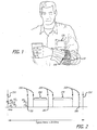
- the microstimulator system as depicted in Figure 1 includes individually addressable, wireless microstimulators 100 that can be injected into one or more muscles or nerves or other tissues of a paralyzed hand to control their activation, thus avoiding the discomfort of trancutaneous stimulation and the invasiveness of surgically implanted multichannel stimulators (see for example, Cameron T, Loeb GE, Peck RA, Scgyknab JH, Strojnic P, Troyk PR, Micromodular implants to provide electrical simulation of paralyzed muscles and limbs, IEEE Trans Biomed Eng 1997; 44: 781-790 ).
- the system further includes an externally worn coil and coil driver 110 that transmits power and command signals inductively to a coil in each of the microstimulators 100.
- the system command and control is performed by the external control unit 120.
- the control unit may be an internal unit installed within the patient's body.
- BIONTM BIONic Neurons; Alfred E. Mann Institute, University of Southern California.
- BIONsTM are a class of implantable medical device: separately addressable, single channel, electronic microstimulators (16 mm long x 2 mm in diameter), that can be injected in or near muscles and nerves to treat paralysis, spasticity and other neurological dysfunctions.
- Microstimulators that may be used in various embodiments are described in US Patent Nos. 5,193,539 ; 5,193,540 ; 5,312,439 ; and 5,324,316 .
- the BION1 system has been used successfully for rehabilitation of patients with various consequences of disuse atrophy (see Dupont Salter AC, Bagg SD et al., "First clinical experience with BION implants for therapeutic electrical stimulation", Neuromodulation 7, 2004, pp 38-47 and Loeb GE, Richmond FJR et al., "BION Injectable Interfaces with Peripheral Nerves and Muscles", Neurosurgical Focus, Vol 20:1-9, May 2006 ).
- FES functional electrical stimulation
- the new BION2 implants include several types of electrical, magnetic and mechanical sensors for limb posture and trajectory (Described in Zou Q, Tan W et all, "Single-axis and Tri-axis Piezoelectric Bimorph Accelerometer", IEEE/ASME Journal of Microelectromechanical Systems, in press , Tan W and Loeb GE, "Feasibility of prosthetic posture sensing via injectable electronic modules", IEEE Trans. Neural Systems & Rehab. Engng., in press , and Sachs NA and Loeb, GE, “Development of a BIONic muscle spindle for prosthetic proprioception", IEEE Trans. Biomedical Engineering, in press ).
- Information obtained from a residual voluntary limb movement can be used to derive commands signaling the intentions of the operator/patient (see Kaliki RR, Davoodi R et all, "The Effects of Training Set on Prediction of Elbow Trajectory from Shoulder Trajectory during Reaching to Targets", 28th Annual International conference IEEE Engineering in Medicine and Biological Society (EMBS), pp 5483-5486 ).
- Information about the posture and trajectory of the limb produced by the FES can be used to adjust the muscle stimulation parameters, much as the central nervous system that normally uses reflexes in order to adjust motor neuron activity.
- Some systems provide stimulation and sensing in different devices (see Gudnason G, Nielsen et all, "A distributed transducer system for functional electrical stimulation", Proc.
- BION The function of a BION system is constrained by the properties of the neuromusculoskeletal system with which it must interact. As the brain learns to control the limbs in infancy, it is effectively performing system identification and developing strategies for dealing with the system that it discovers. In order to build upon those natural strategies, biomimetic design principles have been chosen to be applied where possible, considering how the prosthetic hardware can replace missing functions and enable the reuse of control strategies that have been studied in intact subjects.
- Muscles are composed of hundreds of thousands of individual fibers that are organized into a few hundred motor units, each controlled by a separate motor neuron. Muscle force depends on the number of motor units that have been recruited and their frequencies of firing, as well as nonlinear effects of the length and velocity of motion (shortening or stretching) of the muscle fibers (see Loeb GE and Ghez C, "The Motor Unit and Muscle Action", Principles of Neural Science, 4th Ed Mc Graw Hill 2000, Chapter 34, pp 674-694 ).
- BIONs are usually implanted near the entry zone of the nerve containing the motor axons, where increasing the intensity of pulsatile stimuli can recruit an increasing percentage of the motor units.
- Stimulus efficacy is generally proportional to the charge delivered with each pulse, the product of pulse current and pulse duration. All recruited motor units fire synchronously at the stimulus pulse repetition rate, rather than the asynchronous, smooth modulation typical of physiological recruitment (typically 10-40Hz). If the stimulus rate is set too high, the recruited muscle fibers will fatigue quickly. If it is set too low, the force produced by the muscle may have a substantial ripple at the stimulus rate and it will be difficult to ramp up force quickly or to achieve brief maximal effort such as for responding to perturbations.
- Limb motion is the result of coordinated activity in many muscles with different combinations of actions at joints with varying degrees of freedom. Most muscles cross more than one joint, act on more than one axis of motion, and have moment arms that depend complexly on joint angles. Because muscles can pull but not push, control of joint motion depends on the relative recruitment of antagonistically arranged muscle groups. Because active muscles have spring-like (length-dependent) and dashpot-like (velocity-dependent) contractile properties, contraction of antagonistic muscles can be used to alter the impedance of joints independently from their net torque on the joint.
- Biological muscles are endowed with a variety of sense organs, most prominently including Golgi tendon organs, which sense muscle force, and muscle spindles, which sense combinations of length and velocity that can be adjusted dynamically by the fusimotor gain control system. These signals are combined with those from cutaneous sensors and with the descending command signals from the brain in a sophisticated set of excitatory and inhibitory interneurons in the spinal cord that provide much of the input to the motor neurons. This somatosensory information also projects up to the brain, where it is combined with other sensory modalities such as the acceleration and orientation of the head with respect to gravity.
- the response time of the biological system to perturbations is limited by physiological constraints. Both sensory and motor nerve fibers conduct at approximately 50ms in humans, so the transit delay to and from the spinal cord is on the order of 20-30ms. Muscle fibers respond sluggishly to changes in their neural activation with time constants of about 50ms (rising phase) and 100ms (falling phase) to step changes in that activation. There are also various central delays (1-100ms) while the interneuronal system computes the desired responses at various levels of the spinal cord and brain with varying degrees of integration with other signals (e.g. considerations of interlimb coordination, postural balance, visual feedback, etc.).
- BIONs are not typically intended for a single anatomical site or clinical application. Rather, they can be general-purpose modules intended to be injected where and when they are needed and combined in virtually unlimited ways to support functions that may not have been considered when the system was designed.
- BION2 implants may be used to detect myoelectric command signals for prosthetic limbs and to generate electrotactile sensations to restore a sense of touch from prosthetic hands.
- the number of different muscles that may be controlled prosthetically to perform a given task is highly dependent on the nature of the task and the number of muscles still under voluntary control of the operator.
- the total number of muscles that operate the arm and hand can be in the order of 30-50, depending on how much of the scapular and shoulder motion is included and whether the intrinsic muscles of the hand are included.
- Some clinical applications of FES may require only a few channels, such as to open or close the whole hand around a large object (so-called palmar grasp). The upper limit seems more likely to be set by considerations of cost-benefit.
- Each BION2 implant may have several cost factors not limited to a cost for the device itself, its implantation, and the fitting time required to integrate it into a control algorithm. However, in the exemplary embodiments discussed below the applications may be limited to 20 simultaneously active implants.
- the biological sensorimotor control system is actually quite noisy, with many stochastic processes involved in the transmission and integration of all-or-none action potentials over a small dynamic range of possible frequencies (typically 5-300 pulses per second, pps).
- humans are adept at learning behavioral tactics that minimize its consequences for the performance of individual tasks. This suggested that the requirement for fault tolerance could be expressed more usefully in terms of functional consequences for the task at hand rather than bit-error rates and detection and correction levels.
- the electromyogram is a stochastic pattern of electrical potentials (typically on the order of 100-1000 ⁇ V @ 100-3000Hz when recorded from within a muscle) that arises from the temporospatial overlap of asynchronously firing motor units (see Cameron T, Loeb GE, et all "Micromodular implants to provide electrical stimulation of paralyzed muscles and limbs", IEEE Trans Biomed Eng 1997; 44: 781-790 ). If the patient has a paralyzed limb but there is some residual voluntary control of some muscles, the modulation envelope of their EMG signals can be used to infer the patient's intentions and control the electrical stimulation of the paralyzed muscles.
- the stimulating electrodes already present on the BION can be used to pick up the EMG potentials provided they are disconnected from the stimulus generation circuitry and the first stage amplifier blocks any polarization potentials on the electrodes.
- the EMG signal has a modest signal-to-noise ratio ( ⁇ 40dB) but wide dynamic range. Because of its stochastic nature, any assessment of its amplitude may require integration over as many samples as possible.
- the EMG sensing scheme that is included in BION2 may be based on digitizing the difference in amplitude between successive samples at a rate appropriate for the bandwidth (6kS/s) and integrating the absolute value of those differences for a period of 10-50ms that can be determined dynamically by the external controller (see frame architecture description below).
- a 10-bit analog-to-digital converter (ADC) and a 16-bit accumulator have been chosen to meet these demands.
- the threshold and slope of electrical recruitment can vary widely depending on placement of the implanted stimulator.
- the strength of a stimulus pulse may depend on its charge, the product of pulse current and pulse duration.
- Pulse duration in each of these ranges may be controlled finely over the range 2 to 8000 ⁇ s by counting the internal clock extracted from the incoming 480 kHz RF carrier frequency for power and data.
- the usual firing rates for motor units may be relatively low (20-30 pps) in order to achieve reasonably smooth and minimally fatiguing contractions. But it may be desirable occasionally to provide bursts at much higher frequencies in order to achieve rapid and/or strong contractions or to produce electrotactile sensory percepts. This can be accommodated by the frame architecture described below, which provides a mechanism to generate duplicate or triplicate stimulus pulses with identical parameters within a given frame. Embodiments may also reduce force ripple at low stimulation rates by staggering the stimulus pulses from synergistic sites at different times within each frame.
- An exemplary embodiment may be able to measure the relative recruitment of the muscle in response to each stimulus pulse. This can be used during implantation to help direct a new implant into a site with a low threshold, to map a range of stimulus intensities to a percentage activation of the muscle, and to adjust stimulation parameters on-line to cope with shifts of this recruitment curve due to mechanical deformation of the contracting muscle.
- the same EMG recording and integration subsystem described above can be used for this task and the sampling time may be controlled and synchronized with the stimulation pulse.
- the embodiment may also avoid sampling the initial stimulus artifact and to sample only the so-called M-wave reflecting the immediate response of the activated muscle fibers (typically 1-5 ms window after the stimulus pulse).
- the controller may need information about the starting posture and ongoing trajectory of these movements.
- the communication scheme that is presented next is intended to support all of these sensing functions and the substantial numbers of samples that each might need to collect, hold and transmit each frame.
- the first version BION2 may incorporate only the BIONic Spindle, so the description here provides details only for this posture sensing method and the EMG sensing functions described above.
- the communication protocol for the BION system of the exemplary embodiment is configured to control up to 20 implants in real time.
- BIONs provide a platform for multiple applications and the protocol may provide reconfiguration of similar implants to perform very different tasks with different sensorimotor control requirements.
- the RF powering scheme can poses additional requirements to respond gracefully and rapidly to loss of configurational data stored in volatile RAM if and when individual implants move to a position where their received power drops below a critical level. Most of these aspects may require a selection of a communication protocol based on a sequence of frames, each of which consists of the same number and length of messages and the same order of actions.
- BIONs can be used for a wide range of clinical applications in which different numbers of implants will be used with widely varying requirements for sensing, stimulation and reaction speed.
- the main objective of the communication protocol was to allow the limited bit rate in each direction to be configured as needed for such applications. This configuration occurs during an initialization transmission to each implant, which sets the number of bits and the data that they represent for both forward and reverse telemetry during a given operational session.
- the physical layer is designed to allow full duplex communication with different codification schema and higher data rate for reverse telemetry because of the larger amount of sensory data expected for most applications.
- Forward telemetry in BION1 is via a frequency-shift keyed (FSK) signal over a 480 kHz carrier frequency that provides the clock and power for all implants.
- the data are Manchester-encoded with 2 carrier cycles per state and 2 Manchester-encoded states per bit, resulting in 120 kb/s transmission.
- the reverse telemetry capability is added in BION2 via an on-off keyed (OOK) bursts of a crystal-stabilized 400 MHz carrier whose bandwidth is limited by the boundaries of a single channel in Medical Implant Communications Service (MICS) band (see Falcon C, "Inside implantable Devices", Medical Design Technology, October 2004 and Sivard A, Bradley P et all, "Challenges of in-body communications", Embedded Systems Europe, March 2005 pp 34-37 ). Each bit may occupy one cycle of the 480 kHz master clock, with the presence and absence of carrier signifying ones and zeros, respectively.
- Each reverse telemetry transmission arises in turn from a separate implant, which may preface the actual data with a short, fixed header of ones and zeros to allow the external receiver to determine the appropriate detection threshold.
- the time slots to define the forward and reverse transmissions for each implant may be fixed by the external controller when the system is turned on and the implants are initialized ( Figure 2 ).
- the use of these predefined channels may have few advantages: first, the collisions between transmissions from several BION implants sending data to the controller simultaneously are avoided.
- the controller can identify data from each BION without including extensive headers in back telemetry and each BION can identify the presence of incoming data from the controller also without headers in forward telemetry. All devices and actions may be synchronized by counting clock cycles based on the inward telemetry and power carrier transmitted by the external controller.
- Each frame is a programmed sequence of events that are performed by all implants that may repeat at a rate consistent with the default stimulation frequency for each muscle (typically 20-30pps) or an integer multiple thereof.
- the minimal delay for responding to any sensory feedback or command signal can be two frames. Sensory transduction occurs in one frame to assemble the data sent by reverse telemetry in the next frame, and then the controller computes the desired response and transmits it at the beginning of the third frame for execution during the remainder of that frame.
- the duration of a frame and the exact timing of events within the frame can be controlled by two types of Sync signals that are encoded by special inward telemetry transmissions as violations of Manchester coding that cannot arise from the data sequences themselves.
- a Frame Sync 210 in Figure 2 is a signal that triggers a new sequence of actions.
- the of the protocol a frame is defined as the period between two Frame Syncs 210 and 210' and the frame time is set by the external controller in real time.
- Internal Syncs 220 are signals that can be received at any time inside each frame. These signals may be responsible for triggering each action in the frame (e.g. stimulation, starting and ending points of sensing modalities and reinitialization if necessary) in an order that is programmed as part of the initialization transmission.
- the exemplary embodiment of frame Sync and Internal Sync concepts are illustrated in Figure 2 by the sequence of events included in a frame and their respective timing.
- the first event after a Frame Sync 210 is the communication stage: reverse and forward telemetry from and to each implant, respectively, according to bit counts and time slots that are programmed as part of the initialization of each implant.
- the BIONs wait for the Internal Syncs that are used to trigger various events during the frame.
- the BION example included in Figure 2 stimulates the muscle at 230, measures the muscle response by integrating the M-wave for a variable period 260, M-wave detecting stops and spindle window is triggered 240, detects the joint position by measuring spindle pulses from other implants for the period 270, and finally integrates the background EMG activity over a variable period to provide voluntary command data. All sensor data gathered during these functions are held in a LIFO register until the next frame, when its reverse telemetry slot arrives and it sends the data back to the controller.
- Sync Mask One of the initialization registers is called "Sync Mask” because it determines which BION action (i.e. stimulation or various sensing modes) is triggered by each successive Internal Sync signal.
- BION action i.e. stimulation or various sensing modes
- Sync Mask The combination of Frame Syncs, Internal Syncs and Sync Masks makes the control inside a frame very flexible while permitting tight synchronization of events between implants (e.g. having one implant sense the response to stimuli generated by another implant):
- the integration time of two sensing modalities may be controlled from the outside with Internal Syncs to start and stop the measuring period.
- M-wave measures the muscle response to a stimulus pulse from the same or a different implant. It may vary in latency and duration from muscle to muscle.
- EMG records the residual voluntary control of the muscle. Accuracy may be improved by integrating for as long as possible. By starting and stopping these digital integrators according to the Internal Syncs, the external controller can adjust them dynamically without requiring transmission and storage of these timing parameters.
- Smoothing limb movements in order to produce smooth joint torques, the physiological activity of motor units tends to be asynchronous. To emulate this effect it may be desirable to stimulate synergistic muscles at different times in each frame. This may be another feature that can be achieved by strategically phasing Sync Mask values for stimulation, as shown in Figure 3 .
- the Internal Sync signals that are not used for the corresponding BION are marked with an X and the optional ones are represented as broken lines.
- some of the BION implants in the system are stimulating the muscles at time T1 and some of them at T2. After stimulation, each implant records the M-wave response.
- additional Internal Syncs can be sent, and the double stimulation rate is achieved with the 8th Internal Sync for the first BION and with the 13th for the second one.
- the system communication errors can be classified into critical errors and bearable errors depending on the potential consequences.
- Bearable errors are errors in dynamic data transmission whose possible range may be limited to "safe values” with “dynamic mask” mechanism discussed in this section.
- Critical errors in BION communication that can be avoided are those whose consequences are indeterminate such as sending commands to the wrong implant.
- initialization commands are preceded with the unique 32-bit ID code that is hard-wired into each implant ASIC as Read-Only Memory, similar to the ROM used in radio frequency identification (RFID) transponders.
- RFID radio frequency identification
- each BION echoes the whole initialization sequence of parameters, bit by bit, back to the controller.
- the Dynamic Mask is a register (410) included in each BION whose bits correspond to each bit stored in the parameter registers for stimulation and sensing modalities. The bits shift with every clock in the direction of arrow 415. If a bit in the parameter registers is to be affected by dynamic data on a frame-by-frame basis, its corresponding bit in the dynamic mask register is set to a "1"; if that value is to remain unchanged, its corresponding bit in the dynamic mask register is set to a "0", essentially protecting that bit to stay at the value initially set in the parameter or BION registers 430.
- the buffer 420 shifts in the direction of the arrow 418 when a "1" is received from the mask register 410.
- the bits in the BION registers 430 shift in the direction of the arrow 425 with every clock.
- the simulator consists of two modules, a module to simulate the external controller function and a module to simulate the BION module.
- the two modules are combined to operate a system with one controller and up to 20 implants.
- the Dynamic Mask thus can be used to specify which bits of any parameter of any stimulus or sensing modality are to be changeable and "dynamic" during normal operation ( Figure 4 ).
- the dynamic mask has two purposes: one to avoid dangerous errors and to allow frequently changing parameters to be adjusted while minimizing the number of bits sent in each frame.
- One example of how this might be used is to set the dynamic range of possible stimulation values to cover only the values from threshold to saturation for each muscle.
- the coarse control of stimulus current (n steps of 2n) could be set at one value (e.g. 4mA) and the central five bits of stimulus duration (12 bit counter with 2 ⁇ s clock) would be enabled by the Dynamic Mask so that the only possible stimulus durations would be 16-496us in 16us steps.
- Bearable errors in dynamic parameters are detected with a single parity bit (50% probability) in order to report the occurrence of received errors to the controller during the reverse telemetry phase of the next frame. Because the possible errors have been limited to a safe range by the Dynamic Mask, it may be better for the BION to act with the wrong parameters than to skip stimulation and allow the muscle to relax.
- All of the programmable parameters of an implant can be held in volatile registers that depend on power received by inductive coupling from the external coil-driver.
- the very movement created by the muscle stimulation can cause shifts in the relative alignment between the coil-driver and one or more implants. If the received voltage in a given implant drops under a critical level, that implant goes through a reset operation, clearing all internal registers. Upon the return of sufficient power, this implant no longer participates in the normal communication phase of any ongoing frames unless and until it is completely reinitialized.
- the absence of any detectable reverse telemetry carrier during the pre-assigned time slot for this implant informs the external controller which implant needs reinitialization. In the event of the occasional and isolated drop-outs, the dynamic reinitialization of individual implants is provided without affecting the ongoing performance of the other implants.
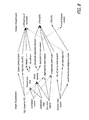
- BION Upon receiving the Internal Sync 511, BION checks for initialization sequence 501. The first part of the initialization sequence must be the complete 32 bit ID code of the implant in question. At step 502, the BION checks for the ID code, If the ID code matches the ID code in the ASIC ROM, the subsequent data are used to initialize all programmable registers at step 503 and the whole initialization sequence will be echoed via reverse telemetry to external controller for complete verification. The implant is now initialized but not yet enabled and in idle 500.
- the enablement occurs only in the next frame by receiving Frame Sync 512 from the external controller, when the external controller detects its reverse telemetry signal at 505 in the predetermined correct time-slot 513 and transmits the first set of dynamic command data 516 in its given predetermined forward telemetry slot 514.
- the dynamic parameters may be processed by the dynamic mask 507 as discussed above.
- Receiving the next Internal Sync at 511 the initialized BION checks to see if the parameters are initialization sequence, if not at step 510 the BIOn checks for the action to be performed by the Internal Sync. If it decides that a stimulation or sensing needs to be performed, the program proceeds to step 509 to do one or the other.
- the state diagram in Figure 5 can be divided into three stages: initialization, communication and stimulation/sensing.
- the controller can reinitialize any device at any time that the device is in the "Idle" state, i.e. not transmitting or receiving data. This can be useful to allow changes in parameters that are outside the previous dynamic range (e.g. the stimulus current in the example above could be shifted from 4mA to 8mA).
- the simulator consists of two modules, a module to simulate the external controller function and a BION module, that are combined to generate a system with one controller and up to 20 implants.
- the input of the controller module is a high level sequence of parameters used to initialize the BIONs and control the system through several subsequent frames, and the output is the sequence of bits that will be sent to each BION along with the times these sequences are to be sent.
- Each simulated BION node is represented by the BION module, and receives the sequence of bits, responds according to the protocol and generates an output file that includes the sequence of states of the implant.
- Each output file records the contents of each register in the BION, the reverse telemetry data output and the states of the signals to activate the different sensing modalities.
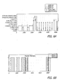
- Figures 6 and 7 show the graphical representation of the simulator output for a complete system and for individual implants respectively.
- Figure 6(a) shows the sequence of events for each one of three BION implants in the system.
- Each BION starts in the idle state and checks the initialization sequence and the ID sent, but only the implant whose ID matches with the ID sent by the controller initializes its registers and sends the echoed data to the controller. This will ensure that the sequence sent was properly received by the BION.
- the external controller After initializing all the implants, the external controller sends a Frame Sync and the three implants wait for their designated RT slot, send the reverse telemetry data, receive new dynamic bits and then process the dynamic data.
- the simulation demonstrates that there is no overlap between RT transmissions from different implants and that each one of the implants receives its new parameters and updates its registers correctly. Once all implants have their dynamic data processed, the external controller sends a series of internal syncs.
- Figure 7 depicts a system having 4 implants from the perspective of an individual implant.
- Figure 7(a) includes the internal register values for BION#2.
- this BION is initialized with the third initialization sequence, which is when this particular implant recognizes its own ID.
- the implant activates its "BION initialized” flag.
- the first frame starts, in which the implant receives a frame sync signal and immediately the "BION enabled” flag is activated.
- the BION then waits for its designated RT slot, when it sends RT, receives the new dynamic bits, processes those dynamic bits and activates the "Stimulation enabled” flag.
- BION#2 stimulates upon the proper internal sync, depending on its "Stimulation sync mask" register.
- stimulation will correspond to the 4th internal sync signal.
- the "Stimulation enabled" flag is deactivated until the new dynamic parameters have been processed.
- the external controller will reinitialize this BION.
- the external controller includes an initialization sequence followed by BION#2 ID and the complete set of initialization parameters. This BION is deactivated in this frame with respect to stimulation and sensing and will be enabled again in the next frame.
- Figure 7(b) includes the same system but from the point of view of BION#3, which is not affected by the BION#2 reinitialization sequence and which, in this case, has its stimulation disabled in the second frame through the dynamic data sent to it by the external controller in that frame.
- the software simulation serves two additional purposes.
- the simulation programs can be used to generate and validate the digital logic blocks for the actual hardware, which will be ultimately compiled into silicon for the implant ASIC and programmed into an FPGA for the external controller.
- it generates valid input and corresponding output files to be compared with the performance of actual hardware during the testing phase.
- the BION2 implant requires 32 bits of ID code plus 137 bits of initialization data for fixed parameters, dynamic mask and control bits.
- One such BION is initialized in 1.14 ms, and a system with 20 BIONs can be initialized in 22.8 ms.
- the maximal duration of the reverse telemetry depends on the length of the LIFO register, presently set to 72 bits but likely to be extended as new sensory modalities become available in future models. The longest duration of the reverse telemetry from 20 such implants would be about 3ms (with all or most of the forward command data to one implant occurring during the reverse-telemetry period of the next implant). If the frame duration is set at 20ms, most of the frame time will be available for stimulating and sensing, with only about 15% required for communication purposes and processing overhead. Such a frame rate would enable continuous adjustment of stimulus parameters at 50Hz, which is about twice the usual firing rate for human muscle fibers. Even higher stimulus rates could be achieved using the repetitive stimulus train capabilities enabled by the Sync Mask.
- the communication protocol disclosed incorporates several strategies useful in systems in which multiple devices with a range of possible functions must be configured dynamically to work with command and data channels that have limited bit rates and non-zero bit error rates.
- a summary of the system characteristics used in BION2 implementation is presented in Figure 8 to illustrate how this system implementation makes possible the fulfillment of the clinical requirements.
- the global signals Frame Sync and Internal Sync and the run-time assignment of bit slots for inward and outward full-duplex telemetry for each device greatly reduces time normally allocated to headers and device addresses in reconfigurable systems.
- the Dynamic Mask disclosed allows the controller to select specific parts of sensing and stimulating parameters for dynamic adjustment, while protecting the system from gross error. This enables aggressive use of the available carrier bandwidth to achieve high data rates without requiring complex and time-consuming error correction.
Landscapes
- Health & Medical Sciences (AREA)
- Life Sciences & Earth Sciences (AREA)
- General Health & Medical Sciences (AREA)
- Public Health (AREA)
- Nuclear Medicine, Radiotherapy & Molecular Imaging (AREA)
- Radiology & Medical Imaging (AREA)
- Engineering & Computer Science (AREA)
- Animal Behavior & Ethology (AREA)
- Veterinary Medicine (AREA)
- Biomedical Technology (AREA)
- Neurology (AREA)
- Neurosurgery (AREA)
- Physical Education & Sports Medicine (AREA)
- Biophysics (AREA)
- Physiology (AREA)
- Prostheses (AREA)
- Electrotherapy Devices (AREA)
Claims (9)
- Steuerung (120) für ein Mikrostimulationsimplantat zur Wiederherstellung der funktionalen Bewegung in einem oder mehreren Muskeln des Körpers eines Patienten, wobei die Steuerung umfasst:a. einen Prozessor, der konfiguriert ist, um Eingabeparameter zu empfangen, ein oder mehrere Implantate (100), die innerhalb des Körpers eines Patienten installiert sind, mit Initialisierungsdaten, die auf den Eingabeparametern basieren, zu initialisieren, und durch das Senden dynamischer Daten verschiedene Prozesse in dem einen oder mehreren Implantaten (100) zu steuern,
worin die Initialisierungsdaten eindeutige Identifikationsdaten für jedes des einen oder mehrerer Implantate sowie Daten umfassen, die erforderlich sind, um es dem einen oder mehreren Implantaten (100) zu ermöglichen, eine oder mehrere Aktionen durchzuführen,
worin die Initialisierungsdaten ferner Daten umfassen, die eine Abfolge von Aktionen definieren, die von dem einen oder mehreren Implantaten (100) in einem Rahmen durchzuführen sind; und
worin die Aktionen die Stimulation eines oder mehrerer Muskeln innerhalb des Körpers des Patienten umfassen;b. einen Sender (110), der konfiguriert ist, um die Initialisierungsdaten mittels Vorwärts-Telemetrie an das eine oder mehrere Implantate (100) zu senden;
worin der Sender (110) ferner konfiguriert ist, um ein Rahmensynchronisationssignal an das eine oder mehrere Implantate (100) zu senden, um den Beginn eines neuen Rahmens auszulösen; worin der Sender (110) ferner konfiguriert ist, um eine oder mehrere interne Synchronisationssignale an das eine oder mehrere Implantate (100) zu senden, nachdem das Rahmensynchronisationssignal gesendet wurde, um eine oder mehrere Aktionen auszulösen, die von dem einen oder mehreren Implantaten (100) gemäß der Initialisierungsdaten, die eine Abfolge von Aktionen im Rahmen definieren, durchzuführen sind; undc. einen Empfänger (110), der konfiguriert ist, um die gesendeten Initialisierungsdaten von dem einen oder mehreren Implantaten (100) mittels Rückwärts-Telemetrie zurückzuempfangen, worin das Zurückempfangen der gesendeten Initialisierungsdaten ein Hinweis an den Prozessor ist, dass die Initialisierungsdaten entsprechend von dem einen oder mehreren Implantaten (100) empfangen wurden;
worin der Empfänger (110) ferner konfiguriert ist, um M-Wellen zu empfangen, die von dem einen oder mehreren Implantaten in Reaktion auf die Muskelstimulation gemessen wurden; undd. worin der Empfänger (110) ferner konfiguriert ist, um Elektromyogramm-(EMG-) Daten zu empfangen, die von dem einen oder mehreren Implantaten detektiert wurden. - Steuerung nach Anspruch 1, worin der Prozessor ferner konfiguriert ist, um die Rahmendauer und die Zeitsteuerung für das eine oder mehrere interne Synchronisationssignale für zu steuern, das/die in jedem Rahmen gesendet wird/werden.
- Steuerung nach Anspruch 1 oder Anspruch 2, worin der Prozessor ferner konfiguriert ist, um den Rahmenbeginn und die Zeitsteuerung des einen oder mehrerer interner Synchronisationssignale mittels Manchester-Kodierung zu kodieren.
- Steuerung nach Anspruch 1, 2 oder 3, worin die empfangenen EMG-Daten der verbliebenen Willkürbewegung eines Muskels des Patienten entsprechen.
- Mikrostimulationsimplantat (100) zur Widerherstellung der funktionalen Bewegung in einem Muskel des Körpers eines Patienten, wobei das Implantat umfasst:a. eine Speichereinheit, die konfiguriert ist, um eindeutige Identifikationsdaten, die dem Implantat zugeordnet sind, zu speichern;b. einen Empfänger, der konfiguriert ist, um Initialisierungsdaten mittels Vorwärts-Telemetrie drahtlos von einer externen Speicherung (120) zu empfangen, worin die Initialisierungsdaten eindeutige Identifikationsdaten sowie Daten umfassen, die erforderlich sind, um die Implantatregister mit einer oder mehreren Aktionen zu programmieren;
worin die Initialisierungsdaten ferner Daten umfassen, die eine Abfolge von Aktionen definieren, die von dem einen oder mehreren Implantaten (100) in einem Rahmen durchzuführen sind;
worin der Empfänger ferner konfiguriert ist, um ein Rahmensynchronisationssignal von der externen Steuerung (120) zu empfangen, um einen Beginn eines neuen Rahmens auszulösen; worin der Empfänger ferner konfiguriert ist, um ein internes Synchronisationssignal von der externen Steuerung (120) zu empfangen, um eine oder mehrere Aktionen auszulösen, die vom Implantat (100) innerhalb des Rahmens durchzuführen sind;c. einen Prozessor, der konfiguriert ist, um die empfangenen Initialisierungsdaten zu empfangen und zu verarbeiten, worin das Verarbeiten das Vergleichen der empfangenen eindeutigen Identifikationsdaten mit den gespeicherten Identifikationsdaten umfasst;d. einen Sender, der konfiguriert ist, um die empfangenen Initialisierungsdaten mittels Telemetrie an die externe Steuerung (120) zurückzusenden , wenn die empfangenen und die gespeicherten eindeutigen Identifikationsdaten übereinstimmen;e. ein Paar von Elektroden, die konfiguriert sind, um einen Muskel innerhalb des Körpers des Patienten basierend auf den programmierten Registern des Implantats zu stimulieren; worin die Elektroden ferner konfiguriert sind, um Elektromyogramm- (EMG-) Potentiale abzufühlen, die der Willkürbewegung des Patienten entsprechen;f. zumindest einen Sensor, der konfiguriert ist, um Signale vom stimulierten Muskel zu detektieren; und worin der Sender ferner konfiguriert ist, um die Daten, die den detektierten Signalen entsprechen, an die externe Steuerung (120) zu senden; worin der Sensor ferner konfiguriert ist, um M-Wellen in Reaktion auf eine Muskelstimulation zu detektieren. - Implantat nach Anspruch 5, worin die Register ein beliebiges aus einem LIFO-Register, einem programmierbaren Register, einem Synchronisationsmaskenregister, einem dynamischen Register oder einem Stimulationsparameterregister sind.
- Neuromuskuläres Implantatsystem zur Widerherstellung der funktionalen Bewegung in einem oder mehreren Muskeln des Körpers eines Patienten, wobei das System umfasst:a. eine die außerhalb des Körpers des Patienten angeordnete Steuereinheit (120), die konfiguriert ist, um eines oder mehrere Implantate (100) mit Initialisierungsdaten zu initialisieren, die Initialisierungsdaten mittels Vorwärts-Telemetrie zu jedem des einen oder mehrerer Implantate (100) zu senden, worin die Initialisierungsdaten eines oder mehrere Muskelstimulationsdaten, Zeitsteuerungsdaten und eindeutige Implantatidentifikationsdaten umfassen;
worin die Steuereinheit (120) ferner konfiguriert ist, um den ordnungsgemäßen Empfang der Initialisierungsdaten durch das eine oder mehrere Implantate (100) zu verifizieren, indem sei die gesendeten Initialisierungsdaten von dem einen oder mehreren Implantaten (100) zurückempfängt;
worin die Steuereinheit (120) ferner konfiguriert ist, um M-Wellen zu empfangen, die von dem einen oder mehreren Implantaten (100) in Reaktion auf die Muskelstimulation gemessen wurden;
worin die Steuereinheit (120) ferner konfiguriert ist, um Elektromyogramm- (EMG-) Daten zu empfangen, die von dem einen oder mehreren Implantaten (100) detektiert wurden; sowieb. ein oder mehrere, innerhalb des Körpers des Patienten installierte Implantate (100) mit gespeicherten, eindeutigen Identifikationsdaten, die konfiguriert sind, um die Initialisierungsdaten zu empfangen und einen oder mehrere Muskeln innerhalb des Körpers des Patienten elektrisch zu stimulieren, Signale zu detektieren, die von dem einen oder mehreren stimulierten Muskeln erzeugt werden, und das detektierte Signal mittels Rückwärts-Telemetrie an die externe Steuereinheit (120) zu senden;
worin die Initialisierungsdaten ferner Daten umfassen, die eine Abfolge von Aktionen definieren, die von dem einen oder mehreren Implantaten (100) in einem Rahmen durchzuführen sind;
worin die Steuereinheit (120) ferner konfiguriert ist, um ein Rahmensynchronisationssignal an das eine oder mehrere Implantate (100) zu senden, um einen Beginn eines neuen Rahmens auszulösen; worin die Steuereinheit (120) ferner konfiguriert ist, um eines oder mehrere interne Synchronisationssignale an das eine oder mehrere Implantate (100) zu senden, um eine oder mehrere Aktionen auszulösen, die von dem einen oder mehreren Implantaten (100) in jedem Rahmen durchzuführen sind. - System nach Anspruch 7, worin die Steuereinheit (120) ferner konfiguriert ist, um die Rahmendauer und die Zeitsteuerung für das eine oder mehrere interne Synchronisationssignale zu steuern, das/die in jedem Rahmen gesendet wird/werden.
- System nach Anspruch 7 worin die empfangenen EMG-Daten der verbliebenen Willkürbewegung eines Muskels des Patienten entsprechen.
Applications Claiming Priority (3)
| Application Number | Priority Date | Filing Date | Title |
|---|---|---|---|
| US80658806P | 2006-07-05 | 2006-07-05 | |
| US11/773,322 US7593776B2 (en) | 2006-07-05 | 2007-07-03 | Flexible communication and control protocol for a wireless sensor and microstimulator network |
| PCT/US2007/015484 WO2008066585A2 (en) | 2006-07-05 | 2007-07-05 | Flexible communication and control for microstimulation network |
Publications (3)
| Publication Number | Publication Date |
|---|---|
| EP2043732A2 EP2043732A2 (de) | 2009-04-08 |
| EP2043732A4 EP2043732A4 (de) | 2012-10-17 |
| EP2043732B1 true EP2043732B1 (de) | 2016-01-13 |
Family
ID=39468406
Family Applications (1)
| Application Number | Title | Priority Date | Filing Date |
|---|---|---|---|
| EP07870716.3A Not-in-force EP2043732B1 (de) | 2006-07-05 | 2007-07-05 | Flexible kommunikation und steuerung für ein mikrostimulationsnetzwerk |
Country Status (3)
| Country | Link |
|---|---|
| US (1) | US7593776B2 (de) |
| EP (1) | EP2043732B1 (de) |
| WO (1) | WO2008066585A2 (de) |
Families Citing this family (38)
| Publication number | Priority date | Publication date | Assignee | Title |
|---|---|---|---|---|
| US6829510B2 (en) * | 2001-12-18 | 2004-12-07 | Ness Neuromuscular Electrical Stimulation Systems Ltd. | Surface neuroprosthetic device having an internal cushion interface system |
| US7632239B2 (en) * | 2005-11-16 | 2009-12-15 | Bioness Neuromodulation Ltd. | Sensor device for gait enhancement |
| US8972017B2 (en) | 2005-11-16 | 2015-03-03 | Bioness Neuromodulation Ltd. | Gait modulation system and method |
| US8209022B2 (en) * | 2005-11-16 | 2012-06-26 | Bioness Neuromodulation Ltd. | Gait modulation system and method |
| US7899556B2 (en) | 2005-11-16 | 2011-03-01 | Bioness Neuromodulation Ltd. | Orthosis for a gait modulation system |
| AU2007245258B2 (en) | 2006-05-01 | 2013-09-19 | Bioness Neuromodulation Ltd. | Improved functional electrical stimulation systems |
| US8457757B2 (en) | 2007-11-26 | 2013-06-04 | Micro Transponder, Inc. | Implantable transponder systems and methods |
| US9089707B2 (en) | 2008-07-02 | 2015-07-28 | The Board Of Regents, The University Of Texas System | Systems, methods and devices for paired plasticity |
| US7847658B2 (en) | 2008-06-04 | 2010-12-07 | Alcatel-Lucent Usa Inc. | Light-weight low-thermal-expansion polymer foam for radiofrequency filtering applications |
| EP2341858B1 (de) | 2008-10-01 | 2014-02-12 | Sherwin Hua | System zur rückenwirbelstabilisierung mithilfe drahtgeführter pedikelschrauben |
| AU2010339720B2 (en) | 2009-12-21 | 2016-07-28 | Sherwin Hua | Insertion of medical devices through non-orthogonal and orthogonal trajectories within the cranium and methods of using |
| US8989857B2 (en) | 2010-11-15 | 2015-03-24 | Sandy L. Heck | Control system and apparatus utilizing signals originating in the periauricular neuromuscular system |
| US8428736B2 (en) | 2011-02-04 | 2013-04-23 | Contour Technology, Inc. | Muscle stimulator and control methods therefor |
| WO2012141714A1 (en) | 2011-04-15 | 2012-10-18 | Johns Hopkins University | Multi-modal neural interfacing for prosthetic devices |
| JP5661555B2 (ja) * | 2011-05-10 | 2015-01-28 | 日本光電工業株式会社 | 交感神経皮膚反応測定装置 |
| US9271864B2 (en) * | 2011-10-04 | 2016-03-01 | Feinstein Patents Llc | Orthosis for range of motion, muscular and neurologic rehabilitation of the lower extremities |
| WO2013069004A1 (en) * | 2011-11-11 | 2013-05-16 | National University Of Ireland, Galway | Apparatus and methods for prevention of syncope |
| US9782587B2 (en) * | 2012-10-01 | 2017-10-10 | Nuvectra Corporation | Digital control for pulse generators |
| US20140163641A1 (en) * | 2012-12-06 | 2014-06-12 | National University Of Singapore | Muscle stimulation system |
| EP2956210A4 (de) * | 2013-02-12 | 2016-10-26 | Univ California | Schaltungsarchitektur für hochspannungs-nervenstimulator mit hoher kanalzahl |
| WO2015142302A1 (en) * | 2014-03-19 | 2015-09-24 | Koc Universitesi | A muscle stimulating device |
| US9867985B2 (en) | 2014-03-24 | 2018-01-16 | Bioness Inc. | Systems and apparatus for gait modulation and methods of use |
| US10674928B2 (en) | 2014-07-17 | 2020-06-09 | Medtronic, Inc. | Leadless pacing system including sensing extension |
| US9399140B2 (en) | 2014-07-25 | 2016-07-26 | Medtronic, Inc. | Atrial contraction detection by a ventricular leadless pacing device for atrio-synchronous ventricular pacing |
| US9492668B2 (en) | 2014-11-11 | 2016-11-15 | Medtronic, Inc. | Mode switching by a ventricular leadless pacing device |
| US9724519B2 (en) | 2014-11-11 | 2017-08-08 | Medtronic, Inc. | Ventricular leadless pacing device mode switching |
| US9492669B2 (en) | 2014-11-11 | 2016-11-15 | Medtronic, Inc. | Mode switching by a ventricular leadless pacing device |
| US9623234B2 (en) | 2014-11-11 | 2017-04-18 | Medtronic, Inc. | Leadless pacing device implantation |
| US9289612B1 (en) | 2014-12-11 | 2016-03-22 | Medtronic Inc. | Coordination of ventricular pacing in a leadless pacing system |
| TWI583357B (zh) | 2015-12-17 | 2017-05-21 | 財團法人工業技術研究院 | 肌肉震動訊號處理系統與方法 |
| CA3010880C (en) | 2016-01-11 | 2024-07-02 | Bioness Medical Inc. | SYSTEMS AND APPARATUS FOR MODULATING GAIT AND METHODS OF USE |
| JP6334588B2 (ja) * | 2016-03-10 | 2018-05-30 | H2L株式会社 | 電気刺激システム |
| US11207527B2 (en) | 2016-07-06 | 2021-12-28 | Cardiac Pacemakers, Inc. | Method and system for determining an atrial contraction timing fiducial in a leadless cardiac pacemaker system |
| AU2018230894B2 (en) | 2017-03-07 | 2022-09-15 | The Alfred E. Mann Foundation For Scientific Research | Multiple implant communications with adjustable load modulation using modulation indices |
| US11160580B2 (en) | 2019-04-24 | 2021-11-02 | Spine23 Inc. | Systems and methods for pedicle screw stabilization of spinal vertebrae |
| US12268422B2 (en) | 2019-11-27 | 2025-04-08 | Spine23 Inc. | Systems, devices and methods for treating a lateral curvature of a spine |
| EP4696279A3 (de) | 2021-05-12 | 2026-03-25 | Spine23 Inc. | Systeme zur stabilisierung der wirbelsäulenwirbel mit pedikelschrauben |
| DE202022104288U1 (de) | 2022-07-28 | 2022-09-21 | Mousumi Bhattacharyya | Fortschrittliches Sprachkommunikationssystem für vollständig gelähmte Personen |
Family Cites Families (9)
| Publication number | Priority date | Publication date | Assignee | Title |
|---|---|---|---|---|
| US4390022A (en) * | 1981-05-18 | 1983-06-28 | Intermedics, Inc. | Implantable device with microprocessor control |
| US5312439A (en) * | 1991-12-12 | 1994-05-17 | Loeb Gerald E | Implantable device having an electrolytic storage electrode |
| US5193539A (en) * | 1991-12-18 | 1993-03-16 | Alfred E. Mann Foundation For Scientific Research | Implantable microstimulator |
| US5193540A (en) * | 1991-12-18 | 1993-03-16 | Alfred E. Mann Foundation For Scientific Research | Structure and method of manufacture of an implantable microstimulator |
| US6083248A (en) * | 1995-06-23 | 2000-07-04 | Medtronic, Inc. | World wide patient location and data telemetry system for implantable medical devices |
| US5864580A (en) * | 1996-08-26 | 1999-01-26 | Hid Corporation | Miniature wireless modem |
| US6044297A (en) * | 1998-09-25 | 2000-03-28 | Medtronic, Inc. | Posture and device orientation and calibration for implantable medical devices |
| US7132173B2 (en) * | 2002-06-28 | 2006-11-07 | Advanced Bionics Corporation | Self-centering braze assembly |
| US7406105B2 (en) * | 2004-03-03 | 2008-07-29 | Alfred E. Mann Foundation For Scientific Research | System and method for sharing a common communication channel between multiple systems of implantable medical devices |
-
2007
- 2007-07-03 US US11/773,322 patent/US7593776B2/en not_active Expired - Fee Related
- 2007-07-05 EP EP07870716.3A patent/EP2043732B1/de not_active Not-in-force
- 2007-07-05 WO PCT/US2007/015484 patent/WO2008066585A2/en not_active Ceased
Also Published As
| Publication number | Publication date |
|---|---|
| EP2043732A2 (de) | 2009-04-08 |
| EP2043732A4 (de) | 2012-10-17 |
| US7593776B2 (en) | 2009-09-22 |
| WO2008066585A2 (en) | 2008-06-05 |
| US20080140154A1 (en) | 2008-06-12 |
| WO2008066585A3 (en) | 2008-11-13 |
Similar Documents
| Publication | Publication Date | Title |
|---|---|---|
| EP2043732B1 (de) | Flexible kommunikation und steuerung für ein mikrostimulationsnetzwerk | |
| Rodríguez et al. | Flexible communication and control protocol for injectable neuromuscular interfaces | |
| Smith et al. | An externally powered, multichannel, implantable stimulator-telemeter for control of paralyzed muscle | |
| US10531944B2 (en) | System for controlling an implantable device on the basis of commands issued by a user | |
| US9108060B2 (en) | Neural prosthesis | |
| US10751539B2 (en) | Active closed-loop medical system | |
| Andreu et al. | A distributed architecture for activating the peripheral nervous system | |
| US6961623B2 (en) | Method and apparatus for controlling a device or process with vibrations generated by tooth clicks | |
| JP2018164730A (ja) | 中枢神経刺激(cns)および末梢神経刺激(pns)のための神経刺激システム | |
| Loeb et al. | RF-powered BIONs/spl trade/for stimulation and sensing | |
| US10252065B2 (en) | Pulse generating system | |
| Popović et al. | Neuroprosthesis and functional electrical stimulation (peripheral) | |
| Schauer et al. | Fusing electrical stimulation and wearable robots with humans to restore and enhance mobility | |
| Rodríguez et al. | Communication and control for reanimating paralyzed limbs via a network of wireless micro-implants | |
| Scott et al. | Command and control interfaces for advanced neuroprosthetic applications | |
| Mundkur | The Bionic Human: A Review of Interface Modalities for Externally Powered Prosthetic Limbs | |
| Osborn et al. | Neural prostheses | |
| Kilgore et al. | Stimulation for Return of Upper-Extremity Function | |
| Micera et al. | A cuff-based neuroprosthesis for hand function restoration: preliminary experiments on animal model | |
| Sacristán et al. | Telemetric Implantable System for Neural Stimulation | |
| Loeb | NEURAL PROSTHETIC INTERFACES BETWEEN NEURAL AND ELECTRONIC COMPUTING | |
| Loeb | Reanimating paralyzed limbs coping with spatially distributed, multimodal systems | |
| Islam | A Survey of Implanted Devices for Neuroprosthesis |
Legal Events
| Date | Code | Title | Description |
|---|---|---|---|
| PUAI | Public reference made under article 153(3) epc to a published international application that has entered the european phase |
Free format text: ORIGINAL CODE: 0009012 |
|
| 17P | Request for examination filed |
Effective date: 20090205 |
|
| AK | Designated contracting states |
Kind code of ref document: A2 Designated state(s): AT BE BG CH CY CZ DE DK EE ES FI FR GB GR HU IE IS IT LI LT LU LV MC MT NL PL PT RO SE SI SK TR |
|
| AX | Request for extension of the european patent |
Extension state: AL BA HR MK RS |
|
| RIN1 | Information on inventor provided before grant (corrected) |
Inventor name: LOEB, GERALD E. Inventor name: WEISSBERG, JACK Inventor name: RODRIGUEZ, NURIA |
|
| DAX | Request for extension of the european patent (deleted) | ||
| A4 | Supplementary search report drawn up and despatched |
Effective date: 20120919 |
|
| RIC1 | Information provided on ipc code assigned before grant |
Ipc: A61N 1/36 20060101ALN20120913BHEP Ipc: A61N 1/372 20060101ALN20120913BHEP Ipc: A61N 1/08 20060101AFI20120913BHEP Ipc: H04B 1/38 20060101ALI20120913BHEP Ipc: H04J 3/06 20060101ALI20120913BHEP |
|
| GRAP | Despatch of communication of intention to grant a patent |
Free format text: ORIGINAL CODE: EPIDOSNIGR1 |
|
| RIC1 | Information provided on ipc code assigned before grant |
Ipc: A61N 1/08 20060101AFI20150610BHEP Ipc: A61N 1/372 20060101ALN20150610BHEP Ipc: H04J 3/06 20060101ALI20150610BHEP Ipc: H04B 1/38 20150101ALI20150610BHEP Ipc: A61N 1/36 20060101ALN20150610BHEP |
|
| INTG | Intention to grant announced |
Effective date: 20150713 |
|
| GRAS | Grant fee paid |
Free format text: ORIGINAL CODE: EPIDOSNIGR3 |
|
| GRAA | (expected) grant |
Free format text: ORIGINAL CODE: 0009210 |
|
| AK | Designated contracting states |
Kind code of ref document: B1 Designated state(s): AT BE BG CH CY CZ DE DK EE ES FI FR GB GR HU IE IS IT LI LT LU LV MC MT NL PL PT RO SE SI SK TR |
|
| REG | Reference to a national code |
Ref country code: GB Ref legal event code: FG4D |
|
| REG | Reference to a national code |
Ref country code: CH Ref legal event code: EP |
|
| REG | Reference to a national code |
Ref country code: IE Ref legal event code: FG4D |
|
| REG | Reference to a national code |
Ref country code: AT Ref legal event code: REF Ref document number: 770096 Country of ref document: AT Kind code of ref document: T Effective date: 20160215 |
|
| REG | Reference to a national code |
Ref country code: DE Ref legal event code: R096 Ref document number: 602007044596 Country of ref document: DE |
|
| REG | Reference to a national code |
Ref country code: LT Ref legal event code: MG4D |
|
| REG | Reference to a national code |
Ref country code: NL Ref legal event code: MP Effective date: 20160113 |
|
| REG | Reference to a national code |
Ref country code: AT Ref legal event code: MK05 Ref document number: 770096 Country of ref document: AT Kind code of ref document: T Effective date: 20160113 |
|
| PG25 | Lapsed in a contracting state [announced via postgrant information from national office to epo] |
Ref country code: NL Free format text: LAPSE BECAUSE OF FAILURE TO SUBMIT A TRANSLATION OF THE DESCRIPTION OR TO PAY THE FEE WITHIN THE PRESCRIBED TIME-LIMIT Effective date: 20160113 |
|
| PG25 | Lapsed in a contracting state [announced via postgrant information from national office to epo] |
Ref country code: GR Free format text: LAPSE BECAUSE OF FAILURE TO SUBMIT A TRANSLATION OF THE DESCRIPTION OR TO PAY THE FEE WITHIN THE PRESCRIBED TIME-LIMIT Effective date: 20160414 Ref country code: ES Free format text: LAPSE BECAUSE OF FAILURE TO SUBMIT A TRANSLATION OF THE DESCRIPTION OR TO PAY THE FEE WITHIN THE PRESCRIBED TIME-LIMIT Effective date: 20160113 Ref country code: IT Free format text: LAPSE BECAUSE OF FAILURE TO SUBMIT A TRANSLATION OF THE DESCRIPTION OR TO PAY THE FEE WITHIN THE PRESCRIBED TIME-LIMIT Effective date: 20160113 Ref country code: FI Free format text: LAPSE BECAUSE OF FAILURE TO SUBMIT A TRANSLATION OF THE DESCRIPTION OR TO PAY THE FEE WITHIN THE PRESCRIBED TIME-LIMIT Effective date: 20160113 |
|
| REG | Reference to a national code |
Ref country code: FR Ref legal event code: PLFP Year of fee payment: 10 |
|
| PG25 | Lapsed in a contracting state [announced via postgrant information from national office to epo] |
Ref country code: PT Free format text: LAPSE BECAUSE OF FAILURE TO SUBMIT A TRANSLATION OF THE DESCRIPTION OR TO PAY THE FEE WITHIN THE PRESCRIBED TIME-LIMIT Effective date: 20160513 Ref country code: AT Free format text: LAPSE BECAUSE OF FAILURE TO SUBMIT A TRANSLATION OF THE DESCRIPTION OR TO PAY THE FEE WITHIN THE PRESCRIBED TIME-LIMIT Effective date: 20160113 Ref country code: LV Free format text: LAPSE BECAUSE OF FAILURE TO SUBMIT A TRANSLATION OF THE DESCRIPTION OR TO PAY THE FEE WITHIN THE PRESCRIBED TIME-LIMIT Effective date: 20160113 Ref country code: LT Free format text: LAPSE BECAUSE OF FAILURE TO SUBMIT A TRANSLATION OF THE DESCRIPTION OR TO PAY THE FEE WITHIN THE PRESCRIBED TIME-LIMIT Effective date: 20160113 Ref country code: IS Free format text: LAPSE BECAUSE OF FAILURE TO SUBMIT A TRANSLATION OF THE DESCRIPTION OR TO PAY THE FEE WITHIN THE PRESCRIBED TIME-LIMIT Effective date: 20160513 Ref country code: SE Free format text: LAPSE BECAUSE OF FAILURE TO SUBMIT A TRANSLATION OF THE DESCRIPTION OR TO PAY THE FEE WITHIN THE PRESCRIBED TIME-LIMIT Effective date: 20160113 Ref country code: PL Free format text: LAPSE BECAUSE OF FAILURE TO SUBMIT A TRANSLATION OF THE DESCRIPTION OR TO PAY THE FEE WITHIN THE PRESCRIBED TIME-LIMIT Effective date: 20160113 |
|
| REG | Reference to a national code |
Ref country code: DE Ref legal event code: R097 Ref document number: 602007044596 Country of ref document: DE |
|
| PG25 | Lapsed in a contracting state [announced via postgrant information from national office to epo] |
Ref country code: DK Free format text: LAPSE BECAUSE OF FAILURE TO SUBMIT A TRANSLATION OF THE DESCRIPTION OR TO PAY THE FEE WITHIN THE PRESCRIBED TIME-LIMIT Effective date: 20160113 Ref country code: EE Free format text: LAPSE BECAUSE OF FAILURE TO SUBMIT A TRANSLATION OF THE DESCRIPTION OR TO PAY THE FEE WITHIN THE PRESCRIBED TIME-LIMIT Effective date: 20160113 |
|
| PLBE | No opposition filed within time limit |
Free format text: ORIGINAL CODE: 0009261 |
|
| STAA | Information on the status of an ep patent application or granted ep patent |
Free format text: STATUS: NO OPPOSITION FILED WITHIN TIME LIMIT |
|
| PG25 | Lapsed in a contracting state [announced via postgrant information from national office to epo] |
Ref country code: CZ Free format text: LAPSE BECAUSE OF FAILURE TO SUBMIT A TRANSLATION OF THE DESCRIPTION OR TO PAY THE FEE WITHIN THE PRESCRIBED TIME-LIMIT Effective date: 20160113 Ref country code: RO Free format text: LAPSE BECAUSE OF FAILURE TO SUBMIT A TRANSLATION OF THE DESCRIPTION OR TO PAY THE FEE WITHIN THE PRESCRIBED TIME-LIMIT Effective date: 20160113 Ref country code: SK Free format text: LAPSE BECAUSE OF FAILURE TO SUBMIT A TRANSLATION OF THE DESCRIPTION OR TO PAY THE FEE WITHIN THE PRESCRIBED TIME-LIMIT Effective date: 20160113 |
|
| 26N | No opposition filed |
Effective date: 20161014 |
|
| PG25 | Lapsed in a contracting state [announced via postgrant information from national office to epo] |
Ref country code: BE Free format text: LAPSE BECAUSE OF FAILURE TO SUBMIT A TRANSLATION OF THE DESCRIPTION OR TO PAY THE FEE WITHIN THE PRESCRIBED TIME-LIMIT Effective date: 20160113 |
|
| PG25 | Lapsed in a contracting state [announced via postgrant information from national office to epo] |
Ref country code: SI Free format text: LAPSE BECAUSE OF FAILURE TO SUBMIT A TRANSLATION OF THE DESCRIPTION OR TO PAY THE FEE WITHIN THE PRESCRIBED TIME-LIMIT Effective date: 20160113 Ref country code: BG Free format text: LAPSE BECAUSE OF FAILURE TO SUBMIT A TRANSLATION OF THE DESCRIPTION OR TO PAY THE FEE WITHIN THE PRESCRIBED TIME-LIMIT Effective date: 20160413 |
|
| REG | Reference to a national code |
Ref country code: CH Ref legal event code: PL |
|
| PG25 | Lapsed in a contracting state [announced via postgrant information from national office to epo] |
Ref country code: MC Free format text: LAPSE BECAUSE OF FAILURE TO SUBMIT A TRANSLATION OF THE DESCRIPTION OR TO PAY THE FEE WITHIN THE PRESCRIBED TIME-LIMIT Effective date: 20160113 |
|
| PG25 | Lapsed in a contracting state [announced via postgrant information from national office to epo] |
Ref country code: LI Free format text: LAPSE BECAUSE OF NON-PAYMENT OF DUE FEES Effective date: 20160731 Ref country code: CH Free format text: LAPSE BECAUSE OF NON-PAYMENT OF DUE FEES Effective date: 20160731 |
|
| REG | Reference to a national code |
Ref country code: IE Ref legal event code: MM4A |
|
| REG | Reference to a national code |
Ref country code: FR Ref legal event code: PLFP Year of fee payment: 11 |
|
| PG25 | Lapsed in a contracting state [announced via postgrant information from national office to epo] |
Ref country code: IE Free format text: LAPSE BECAUSE OF NON-PAYMENT OF DUE FEES Effective date: 20160705 |
|
| PG25 | Lapsed in a contracting state [announced via postgrant information from national office to epo] |
Ref country code: LU Free format text: LAPSE BECAUSE OF NON-PAYMENT OF DUE FEES Effective date: 20160705 |
|
| PG25 | Lapsed in a contracting state [announced via postgrant information from national office to epo] |
Ref country code: HU Free format text: LAPSE BECAUSE OF FAILURE TO SUBMIT A TRANSLATION OF THE DESCRIPTION OR TO PAY THE FEE WITHIN THE PRESCRIBED TIME-LIMIT; INVALID AB INITIO Effective date: 20070705 Ref country code: CY Free format text: LAPSE BECAUSE OF FAILURE TO SUBMIT A TRANSLATION OF THE DESCRIPTION OR TO PAY THE FEE WITHIN THE PRESCRIBED TIME-LIMIT Effective date: 20160113 |
|
| REG | Reference to a national code |
Ref country code: FR Ref legal event code: PLFP Year of fee payment: 12 |
|
| PG25 | Lapsed in a contracting state [announced via postgrant information from national office to epo] |
Ref country code: TR Free format text: LAPSE BECAUSE OF FAILURE TO SUBMIT A TRANSLATION OF THE DESCRIPTION OR TO PAY THE FEE WITHIN THE PRESCRIBED TIME-LIMIT Effective date: 20160113 Ref country code: MT Free format text: LAPSE BECAUSE OF NON-PAYMENT OF DUE FEES Effective date: 20160731 |
|
| PGFP | Annual fee paid to national office [announced via postgrant information from national office to epo] |
Ref country code: FR Payment date: 20180612 Year of fee payment: 12 |
|
| PGFP | Annual fee paid to national office [announced via postgrant information from national office to epo] |
Ref country code: DE Payment date: 20180619 Year of fee payment: 12 |
|
| PGFP | Annual fee paid to national office [announced via postgrant information from national office to epo] |
Ref country code: GB Payment date: 20180704 Year of fee payment: 12 |
|
| REG | Reference to a national code |
Ref country code: DE Ref legal event code: R119 Ref document number: 602007044596 Country of ref document: DE |
|
| GBPC | Gb: european patent ceased through non-payment of renewal fee |
Effective date: 20190705 |
|
| PG25 | Lapsed in a contracting state [announced via postgrant information from national office to epo] |
Ref country code: GB Free format text: LAPSE BECAUSE OF NON-PAYMENT OF DUE FEES Effective date: 20190705 Ref country code: DE Free format text: LAPSE BECAUSE OF NON-PAYMENT OF DUE FEES Effective date: 20200201 |
|
| PG25 | Lapsed in a contracting state [announced via postgrant information from national office to epo] |
Ref country code: FR Free format text: LAPSE BECAUSE OF NON-PAYMENT OF DUE FEES Effective date: 20190731 |