EP2042974B1 - Verfahren zur Stabilisierung der Positionsdaten in einer Digitalisiertablett - Google Patents
Verfahren zur Stabilisierung der Positionsdaten in einer Digitalisiertablett Download PDFInfo
- Publication number
- EP2042974B1 EP2042974B1 EP20080016910 EP08016910A EP2042974B1 EP 2042974 B1 EP2042974 B1 EP 2042974B1 EP 20080016910 EP20080016910 EP 20080016910 EP 08016910 A EP08016910 A EP 08016910A EP 2042974 B1 EP2042974 B1 EP 2042974B1
- Authority
- EP
- European Patent Office
- Prior art keywords
- window size
- pointer
- tablet
- filter
- jitter
- Prior art date
- Legal status (The legal status is an assumption and is not a legal conclusion. Google has not performed a legal analysis and makes no representation as to the accuracy of the status listed.)
- Ceased
Links
Images




Classifications
-
- G—PHYSICS
- G06—COMPUTING OR CALCULATING; COUNTING
- G06F—ELECTRIC DIGITAL DATA PROCESSING
- G06F3/00—Input arrangements for transferring data to be processed into a form capable of being handled by the computer; Output arrangements for transferring data from processing unit to output unit, e.g. interface arrangements
- G06F3/01—Input arrangements or combined input and output arrangements for interaction between user and computer
- G06F3/03—Arrangements for converting the position or the displacement of a member into a coded form
- G06F3/041—Digitisers, e.g. for touch screens or touch pads, characterised by the transducing means
- G06F3/0416—Control or interface arrangements specially adapted for digitisers
- G06F3/0418—Control or interface arrangements specially adapted for digitisers for error correction or compensation, e.g. based on parallax, calibration or alignment
- G06F3/04186—Touch location disambiguation
-
- G—PHYSICS
- G06—COMPUTING OR CALCULATING; COUNTING
- G06F—ELECTRIC DIGITAL DATA PROCESSING
- G06F3/00—Input arrangements for transferring data to be processed into a form capable of being handled by the computer; Output arrangements for transferring data from processing unit to output unit, e.g. interface arrangements
- G06F3/01—Input arrangements or combined input and output arrangements for interaction between user and computer
- G06F3/03—Arrangements for converting the position or the displacement of a member into a coded form
- G06F3/041—Digitisers, e.g. for touch screens or touch pads, characterised by the transducing means
- G06F3/044—Digitisers, e.g. for touch screens or touch pads, characterised by the transducing means by capacitive means
-
- G—PHYSICS
- G06—COMPUTING OR CALCULATING; COUNTING
- G06F—ELECTRIC DIGITAL DATA PROCESSING
- G06F3/00—Input arrangements for transferring data to be processed into a form capable of being handled by the computer; Output arrangements for transferring data from processing unit to output unit, e.g. interface arrangements
- G06F3/01—Input arrangements or combined input and output arrangements for interaction between user and computer
- G06F3/03—Arrangements for converting the position or the displacement of a member into a coded form
- G06F3/041—Digitisers, e.g. for touch screens or touch pads, characterised by the transducing means
- G06F3/0416—Control or interface arrangements specially adapted for digitisers
- G06F3/0418—Control or interface arrangements specially adapted for digitisers for error correction or compensation, e.g. based on parallax, calibration or alignment
- G06F3/04182—Filtering of noise external to the device and not generated by digitiser components
-
- G—PHYSICS
- G06—COMPUTING OR CALCULATING; COUNTING
- G06F—ELECTRIC DIGITAL DATA PROCESSING
- G06F3/00—Input arrangements for transferring data to be processed into a form capable of being handled by the computer; Output arrangements for transferring data from processing unit to output unit, e.g. interface arrangements
- G06F3/01—Input arrangements or combined input and output arrangements for interaction between user and computer
- G06F3/03—Arrangements for converting the position or the displacement of a member into a coded form
- G06F3/041—Digitisers, e.g. for touch screens or touch pads, characterised by the transducing means
- G06F3/046—Digitisers, e.g. for touch screens or touch pads, characterised by the transducing means by electromagnetic means
Definitions
- the present invention relates to a method and apparatus for stabilizing coordinates measured and output by a pointing device or digitizer tablet, a pointing device or digitizer tablet including the apparatus, and a computer readable medium and driver for performing the method.
- the present invention also relates to a height dependent filter usable to reduce jitter in a pointing device or digitizer tablet.
- Pointing devices are computer peripherals used for drawing or navigating on a computer system. They consist of a flat sensing area and an associated pointer. They can be in the form of a graphics tablets, comprised of a sensing tablet and a pointing tool that is usually either pen shaped or mouse shaped. Graphics tablets measure X and Y coordinate positions of the tool as well as other parameters, such as pen tip pressure, pen tilt angle, pen axial rotation, mouse buttons, mouse rotation, etc. A user manipulates the tool over the tablet surface for tracing, drawing, writing, manipulating graphical data, or navigating in a graphical user interface. The tablet is usually attached to a host computer and the graphical data is displayed either on a separate display or one integral with the computer.
- a touch tablet has a surface that is sensitive to being touched by a user's finger, which acts as the pointing tool.
- the touch tablet measures X and Y coordinate positions, contact with the user's finger, and other parameters such as contact area.
- the user touches the surface of the touch tablet, usually placed in front of a display, to select or manipulate objects on the display.
- Various underlying technologies can be used for detecting the pointing device or tool position in graphics tablets.
- One common technology is electromagnetic, where the position of the tool is detected by interpolating signal strength across a series of sensing coils in the tablet.
- Another technology is electrostatic, where the position of the tool is detected by interpolating signal strength across a series of electrodes in the tablet.
- Touch tablets can use capacitive coupling between the user's finger and the tablet to detect finger position.
- the position of the user's finger can be interpolated from signal levels at electrodes at the edges of the tablet, or between a series of electrodes located in the tablet.
- An electric field created by the electrodes can extend above the surface of the tablet to allow measurement of the coordinates above the surface.
- the detection, interpolation, and transmission of the resulting coordinate position is performed in real-time so that the user can observe his or her actions on the computer monitor or display device.
- the signal Since the detection of the signal strength at the electrodes of the touch tablet or at the coils of the graphics tablet requires measuring the amplitude of an analog signal, the signal is susceptible to interference or noise from external sources. This noise manifests itself as instability in measured coordinate positions and is known as jitter. Jitter has a fairly random distribution usually with Gaussian properties and a predictable range for any given environment, but is unpredictable from sample to sample.
- Jitter has a time scale that is the same as the time scale of the sampling, which is generally around 100-200 Hz. Since user movements are generally on a time scale of less than 20 Hz, a variety of low-pass filters can be used to separate the two signals, that is, the coordinate position signal from the noise or interference created by the external sources. However, significant effort must be taken to avoid introducing filtering artifacts. Filtering artifacts occur when the low pass filtering removes high frequency content from the position signal which actually represents valid user input data.
- the object of the invention is solved by a method according to claim 1 and a digitizer tablet according to claim 5.
- Claims 2 to 4 refer to a specifically advantageous realization of the method according to claim 1
- claims 6 to 10 relate to a specifically advantageous realization of the digitizer tablet according to claim 5.
- a method of reducing jitter over a range of tool heights above a surface of a pointing device includes determining the height of a tool above a tablet surface and adjusting parameters of a jitter reduction filter based on the determined height. The position of the tool on the tablet surface is measured, and the adjusted jitter reduction filter is then applied to filter the measured position of the tool. Then, the filtered position is reported.
- This method includes the step of adjusting a depth of a rectangular filter. Furthermore it is preferred that the step of adjusting the depth of the rectangular filter can only increase by one for each coordinate measurement. It is further preferred that the step of adjusting the depth of the rectangular filter can only decrease by one or two for each coordinate measurement.
- the adjustment of the parameters of the jitter reduction filter comprises adjusting the parameters of a finite response filter.
- a method of stabilizing positional data in a digitizer tablet, preferably associated with a display device, and for reporting a position of a pointer includes detecting a current location of the pointer with respect to a coordinate grid defined on the tablet and outputting a position signal indicative of the current pointer location. Noise is filtered from the position signal based on at least one filter parameter.
- the height of the pointer above the tablet is determined, and an amount of jitter in the position signal is estimated based on the determined distance.
- the at least one filter parameter is adjusted based on the estimated amount of jitter.
- a digitizer tablet for digitizing a position of a pointer is also provided.
- the digitizer tablet is preferably associated with a display device for reporting the position of the pointer.
- a position detecting unit defines a coordinate grid on a surface of the tablet, and includes at least one sensing element for detecting a current location of the pointer with respect to the coordinate grid. The position detecting unit then outputs a position signal indicative of the current pointer location.
- a filtering unit filters noise from the position signal based on at least one filter parameter.
- a jitter estimating unit for estimating an amount of jitter in the position signal, which is based on the height of the pointer above the tablet, is provided.
- a filter parameter adjustment unit adjusts the at least one filter parameter of the filtering unit based on the amount of jitter estimated by the jitter estimating unit.
- Said filtering unit of said digitizer tablet comprises a rectangular windowing filter. At each value of the position signal, said rectangular windowing filter averages the most recent N output position sample values to determine a current value of the position signal. It is further preferred that the at least one filter parameter comprises a window size of said rectangular windowing filter.
- said filter parameter adjustment unit adjusts the filter depth gradually, thereby especially avoiding dramatic changes in the filtered position signal.
- the pointer comprises one or more of a stylus or a user finger.
- an analog electromagnetic signal 100 received by a tablet 102 (see Figures 3A and 3B ) when a pointer 104 is disposed at a tablet surface 106 is stronger than a signal 100' received by the tablet 102 when the pointer 104 is moved away from the tablet surface 106.
- the signal-to-noise ratio (SNR) decreases as the pointer 104 is moved away from the tablet 102. Accordingly, adaptive filtering of the interference from a position signal detected by the tablet 102 can be performed based on different SNRs so as to minimize the introduction of filtering artifacts or distortion.
- a pointer device 108 includes the pointer 104 and the tablet 102 including a plurality of sensing elements 110 disposed below the tablet surface 106 for measuring the position of the pointer 104 with respect to the tablet surface 106.
- the sensing elements 110 may be inductive coils or capacitive sensors as in a graphics tablet or a touch tablet.
- an apparatus 112 for reducing jitter in position data measured and output by the pointer device 108 includes a position detecting unit 114, a height determining unit 116, a filtering unit 118, a filter parameter adjustment unit 120, and an output unit 122.
- the position detecting unit 114 detects the position of the pointer 104 with respect to a coordinate system defined on the tablet surface 106 by sensing elements 110 of the pointer device 108 shown in Figures 3A and 3B .
- the position detecting unit 114 detects an analog position indicating signal received from the pointer 104, samples the position indicating signal, and determines the location of the pointer 104 at each sample based on the value of the sampled position indicating signal.
- the output unit 122 displays a coordinate position of the pointer 104 along the tablet surface 106.
- the output unit 122 may be a computer monitor or screen that reports position of the pointer 104 to a user in real-time using a cursor.
- the height determining unit 116 determines the current height of the pointer 104 from the tablet surface 106 either independently of the position detecting unit 114 or based on an input received from the position detecting unit 114. For example, when the height determining unit 116 is independent of the position detecting unit 114, an independent electromagnetic or electrostatic interaction with the pointer 104 is generated by the height determining unit 116 using a predefined electromagnetic or electrostatic field. To this end, one or more auxiliary electrodes or sensor coils (not shown) are disposed on the tablet 102 for sensing the interaction with the pointer 104 to determine the height of the pointer 104 with respect to the tablet surface 106.
- the height or distance determining unit 116 may detect the height or distance of the pointer 104 based on an input received from the position detecting unit 114.
- the height determining unit 116 may store a table of heights associated with a plurality of detected signal strength values.
- the height determining unit 116 may look up the signal strength provided by the position detecting unit 114 and determine the corresponding height as the current height of the pointer 104 above the tablet surface 106.
- the height determining unit 116 may alternatively be a noise estimation unit, an SNR estimation unit, or a jitter estimation unit that estimates the SNR of the signal received from the pointer 104 or the jitter in the position data.
- the dashed line in Figure 4 represents communication between the height determining unit 116 and the position detecting unit 114 in an embodiment in which the height determining unit 116 determines the height of the pointer 104 based on an input from the position detecting unit 114.
- the signal strength of the position indicating signal transmitted by the pointer 104 and sensed by the sensing elements 110 may be used to determine the height of the pointer 104, for example, in accordance with the signal diagrams of Figures 1 and 2 .
- the height determining unit 116 may include a spatial capacitive overlay disposed on the tablet surface 106, which projects an energy field and recognizes movement as the projected energy field is penetrated by the pointer 104.
- the height determining unit 116 can discern between a hand, arm, or other object and can track movement within the field to interpret the intention of the user. Accordingly, by tracking the movement within the projected field, the height determining unit 116 can determine the height of the pointer 104 with respect to the tablet 102 independently of the measurement conducted by the position detecting unit 114.
- the spatial capacitive overlay may be a system previously available from TouchKO or available from the assignee hereof.
- the spatial capacitive overlay system may be the system described in U.S. Patent Application No. 11/211,272 .
- the filtering unit 118 filters the position signal values output from the position detecting unit 114 to remove the effect of interference, thereby reducing jitter based on one or more filter parameters, such as filter depth or window size.
- the filtering unit 118 may include a low-pass filter for removing high frequency interference introduced by components surrounding the tablet 102.
- the filter parameters of the filtering unit 118 are adjusted by the filter parameter adjustment unit 120 based on the height of the pointer 104 determined by the height determining unit 116.
- the filter parameter adjustment unit 120 may adjust the filter parameters based on the estimated SNR of the position indicating signal received by the position detecting unit 114 or the estimated jitter in the position signal values determined by the position detecting unit 114.
- the low-pass filter is a moving average or rectangular windowing filter.
- N is a small number such as four.
- the larger the value of N the more high frequency data is filtered out, and the more jitter is decreased.
- also encoded with this high frequency data is any abrupt change in direction of the pointer 104.
- N is increased, the filtering artifacts resulting from smoothing abrupt changes in pointer direction become more pronounced.
- An example of this artifact is that a sharp right angle made with the pointer 104 rounds into a gentle curve. This causes distortion of drawn figures, such as the letter L or an image of a rectangle.
- the coordinate position presented by the output unit 122 tends to lag behind the actual position of the pointer 104, that lag being on the order of N divided by twice the frequency. For example, with an N of 4 and a sampling frequency of 100 Hz, the lag is approximately 1/50 th of a second. If N is increased to 8, the lag increases to 1/25 th of a second. While most people find 1/50 th of a second of lag to be unnoticeable, they also find 1/25 th of a second of lag to be unacceptable.
- the noise in the measured position indicating signal tends to come from sources away from the tablet 102 and tends to fluctuate randomly from sample to sample, the noise fluctuations can be averaged in order to approximate the noise level over time as being relatively constant.
- the desired position indicating signal received from the pointer 104 at the tablet 102 decreases in strength as the distance of the pointer 104 from the tablet 102 increases due to signal attenuation. It can be seen in Figures 1 and 2 that in the detected position indicating signal, the SNR decreases as the distance of the pointer 104 from the tablet 102 increases. When the SNR decreases, the influence of noise on the detection of the position indicating signal also increases. This leads to increased jitter as the pointer 104 moves further from the tablet surface 106.
- the filter parameter adjustment unit 120 adjusts one or more filter parameters, such as filter depth or window size, of the filtering unit 118 to minimize the amount of jitter in the position signal values while reducing the amount of artifacts and filter distortion introduced by the filtering unit 118 based on the height of the pointer 104 detected by the height determining unit 116.
- the height of the pointer 104 is used to approximate the jitter.
- the filter period N of the filtering unit 118 is adjusted to account for more or less jitter.
- the filter period N is increased when there is more jitter and decreased when there is less jitter.
- the filter period N is also referred to as the filter depth of the filtering unit 118.
- the filter period N may be initially set based on sensing characteristics of the pointing device 108.
- the filter period N may be initially set to 4 when the pointer 104 is in contact with the tablet surface 106.
- the filter period N may be varied between 4 and 8 based on the height of the pointer 104. The manner and amount by which the filter period N is adjusted is further described in detail below.
- the value of N is decreased to decrease the filter window size, thereby removing less of the high frequency content from the position signal value and decreasing the amount of distortion or filtering artifact introduced by the filtering unit 118.
- the filtering unit 118 filters the position signal values received from the position detecting unit 114 and provides the filtered position signal values to the output unit 122.
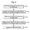
- a method of reducing jitter in position data measured and output by the pointer device 108 includes determining the height of the pointer 104 above the tablet surface 106 at step S124. Then, at step S126, the parameter(s) of the jitter reduction filter, such as the filtering unit 116 shown in Figure 4 , are adjusted based on the height determined in step S124. In step S126, the window size, period N, or the "depth" of the filtering unit 116 can be adjusted based on the height of the pointer 104 above the tablet surface 114.
- step S128 the position or position value of the pointer 104 along the coordinates of the tablet surface 106 is measured using the sensing elements 110 of the tablet 102 shown in Figures 3A and 3B .
- the measured position signal value is filtered by the jitter reduction filter using the parameters adjusted at step S126.
- the filtered position signal value is then output to a display device or other position reporting mechanism at step S 132 to indicate to a user the position of a cursor in real-time.
- Figures 6A and 6B illustrate an exemplary operation of the present embodiment of the invention.
- Figure 6A illustrates a rectangular windowing filter being applied when the pointer 104 is at height (h 1 ) from the tablet surface 106 as shown in Figure 3A
- Figure 6B shows the rectangular windowing filter being applied when the pointer 104 is at height (h 2 ) from the tablet surface 106 as shown in Figure 3B
- the filter depth of the filter can be varied based on the relative height or estimated jitter differences.
- the filter period N which can also be referred to as the filter depth (d)
- the filter depth (d) may be set to other integers.
- Figures 6A and 6B only show the position values along the X-axis, it should be understood that Y-axis position values can be filtered in the same manner.
- the parameter of the rectangular windowing filter can be derived as follows.
- the relative height of the pointer 104 need only be considered, so the actual height from the tablet 102 is immaterial. Therefore, to make subsequent calculations simpler, we normalize the height, defining the height at which the pointer 104 touches the tablet 102 as the minimum height ( h 0 ) and giving the minimum height a value of 0.
- the measured (or calculated) jitter at h 0 is designated as j 0
- the measured (or calculated) jitter at h 1 is designated as j 1 .
- the jitter j 0 at the tablet surface h 0 is a constant and the jitter j 1 at the maximum height h 1 is also constant.
- the term ( j 1 / j 0 - 1) is also constant for any particular tablet.
- jitter qualities and a particular sampling frequency which can be used to determine an ideal low-pass filter, such as a rectangular windowing filter.
- a basic depth d 0 of the afore-mentioned filtering unit 118 on the surface 106 of the tablet 102 can be selected to reduce jitter at the surface 106 ( j 0 ) to unnoticeable levels without presenting filtering artifacts.
- the filter depth can be scaled linearly in discrete integer quantities with tablet jitter. Rounding can be used to achieve these discrete integer changes in filter depth.
- a ceiling function, a floor function, or the like may be used to round to the nearest integer.
- the ceiling function returns the smallest integer that is greater than or equal to a real number
- the floor function returns the largest integer that is less than or equal to a real number.
- a floor function is used.
- Equation 7 For the height-adaptive rectangular windowing filter, there are a number of factors that can be considered to improve performance of the filtering unit 118.
- Growing the filter by one sample, or increasing the filter depth by one makes the lag of the resulting coordinate one-half sample greater than the previous filter window.
- the filter depth is decreased by one, the lag of the resulting coordinate is one half sample less than that of the previous filter window.
- the method shown in Figure 7 may be used to gradually increase or decrease the filter depth in accordance with the change in height of the pointer 104.
- the method of Figure 7 spreads the increases in filter depth over a number of samples equal to the size of the change.
- the increases in filter depth are made gradual by the method of Figure 7 by increasing the filter depth by 1 for each sample until the proper filter depth is obtained. For example, if the pointer 104 is suddenly moved from the tablet surface 106 away from the tablet 102, rather than suddenly increasing the filter depth by a relatively large number, for example 4, for the current sample according to Equation 7, the increase in filter depth is performed over more than one sample, as prescribed by the method of Figure 7 .
- the manner in which the position values are filtered does not change dramatically from sample to sample.
- Reductions in filter depth may be handled in a similar manner. That is, the method of Figure 7 may also be used to make relatively large reductions in filter depth gradually. For changes that would be dramatic, the filter depth change is spread out over approximately half the number of samples. It should be noted that the method of Figure 7 may correspond to step S126 of the method shown in Figure 5 . The method of Figure 7 is performed once at each sample to determine the proper adjustment of the filter depth.
- step S200 it is determined whether the new or proposed filter depth (d h ) is larger than the previous filter depth (d h-1 ). If it is determined in step S200 that the new filter depth (d h ) is larger than the previous filter depth (d h-1 ), then a filter depth that is one larger than the previous filter depth (d h-1 ) is used in the filtering operation performed by the filtering unit 118 at step S202.
- step S204 is performed to determine whether the new filter depth (d h ) is much smaller than the previous filter depth (d h-1 ). If it is determined in step S204 that the new filter depth (d h ) is much smaller than the previous filter depth (d h-1 ), step S206 is performed to use a filter depth that is two smaller than the previous filter depth (d h-1 ). A threshold value may be used to determine whether the new filter depth (d h ) is much smaller (or larger) than the previous filter depth (d h-1 ).
- the difference between the new or proposed filter depth (d h ) and the previous filter depth (d h-1 ) may be calculated and then compared to the threshold value. If the calculated difference is larger than the threshold value, the new filter depth (d h ) is determined to be much smaller than the previous filter depth (d h-1 ). Similarly, if the calculated difference is less than or equal to the threshold value, the new filter depth (d h ) is determined not to be much smaller than the previous filter depth (d h-1 ).
- step S204 If it is determined in step S204 that the new filter depth (d h ) is not much smaller than the previous filter depth (d h-1 ), it is determined at S208 whether the new filter depth (d h ) is smaller than the previous filter depth (d h-1 ). If the new filter depth (d h ) is determined to be smaller than the previous filter depth (d h-1 ) at step S208, step S210 is performed to use a filter depth that is one smaller than the previous filter depth (d h-1 ).
- step S212 is performed to use a filter depth that is equal to the previous filter depth (d h-1 ).
- the threshold value used to determine whether the proposed filter depth (d h ) is much smaller than the previous filter depth (d h-1 ) may be set to an integer, such as 3 or 4. For purposes of this explanation, we can assume the threshold value is 4. Any large difference between the proposed filter depth (d h ) and the previous filter depth (d h-1 ) would not be reflected in a single filter depth adjustment for one sample. If the proposed filter depth (d h ) is less than the previous filter depth (d h-1 ) by 4 or more, for example if the proposed filter depth (d h ) is 4 and the previous filter depth (d h-1 ) is 8, the filter depth adjustment would instead be performed over three consecutive samples as opposed to one sample.
- the filter depth of 8 would be decreased at a first sample by a first decrement of 2 at step S206 because the proposed filter depth (d h ) 4 is determined to be much smaller than the previous filter depth (d h-1 ) 8 at step S204 based on the threshold value.
- the filter depth of 6 would then be decreased again at a second sample by a second decrement of 1 at step S210 because the proposed filter depth (d h ) 4 is determined to be smaller (not much smaller) than the previous filter depth (d h-1 ) 6 at step S208.
- the filter depth of 5 would then be decreased again at a third sample by a third decrement of 1 at step S210 because the proposed filter depth (d h ) 4 is determined to be smaller (not much smaller) than the previous filter depth (d h-1 ) 5 at step S208. Accordingly, the proposed filter depth of 4 is obtained. On the other hand, if the proposed filter depth (d h ) is greater than the previous filter depth (d h-1 ), the filter depth adjustment is performed in consecutive samples in repeated increments of 1 at step S202.
- the method of Figure 7 increments the filter depth by one at each sample until the filter depth of 7 is obtained.
- the method of adjusting filtering parameters shown in Figure 7 assures that the filter parameter is gradually adjusted without dramatic changes, regardless of whether the relative height of the pointer 104 or relative jitter changes dramatically from sample to sample. As a result, there are no dramatic changes in the values of x' , which represents the filtered position signal value.
- jitter reducing apparatus 112 of Figure 4 and the methods of Figures 4 and 7 can be applied to various other windowing filters, or used in conjunction with other classes of filters, such as adaptive finite impulse response filters, an example of which is described in U.S. Patent No. 5,179,254 .
- the filter parameter adjustment unit 120 may include a memory in which various height values are associated with jitter values and/or filter parameter values. Thus, when the height value is determined, the filter parameter adjustment unit 120 retrieves the corresponding filter parameter value or jitter value and controls the filtering unit 118, accordingly.
- the apparatus and methods of the various embodiments of the present invention can be implemented in a host application or in a system level driver.
- driver may be implements as software or firmware and may be resident on in the tablet or the CPU of the host computer.
- the filtering could be implemented in the tablet 102 itself, either as firmware of a processor or as a custom IC built specifically for the filtering unit 118. That is, the apparatus 112 of Figure 4 and/or the methods of Figures 5 and 7 may be implemented by an integrated circuit in the tablet 102 or host computer to which the tablet 102 is connected.
- the apparatus 112 of Figure 4 or the methods of Figures 5 and 7 may be embodied as computer readable codes on a computer readable recording medium running on the tablet 102 itself or as a system driver running on the host computer.
- the computer readable recording medium may be any data storage device that can store data which can be thereafter read by a computer system. Examples of the computer readable recording medium include read-only memory (ROM), random-access memory (RAM), CD-ROMs, flash memory, downloadable instructions, magnetic tapes, floppy disks, optical data storage devices, and carrier waves (such as data transmission through the Internet), among other things.
- the relative jitter function described above may be made dependent on measurements other than height. Such measurements could include, but would not be limited to, the coordinate(s) being measured, the perpendicular coordinate, or some other value, such as a direct measurement or approximation of interfering radiation and/or signal strength.
- the pointer 104 as defined herein may be a pointing device, such as a stylus, or a user's finger which may be electromagnetically or electrostatically coupled to the tablet 102.
- the pointer device 108 may be a graphics tablet, a digitizer tablet, or a touch tablet, which may be used for graphic design or other applications. It will also be appreciated that the tablet 102 may be integrated with the screen of a display device in a touch screen or tablet computer.
Landscapes
- Engineering & Computer Science (AREA)
- General Engineering & Computer Science (AREA)
- Theoretical Computer Science (AREA)
- Physics & Mathematics (AREA)
- Human Computer Interaction (AREA)
- General Physics & Mathematics (AREA)
- Electromagnetism (AREA)
- Position Input By Displaying (AREA)
- Measurement Of Length, Angles, Or The Like Using Electric Or Magnetic Means (AREA)
- User Interface Of Digital Computer (AREA)
Claims (10)
- Verfahren zum Stabilisieren von Positionsdaten in einem Digitalisier-Tablet (102) für ein Melden einer Position eines Zeigers (104), wobei das Verfahren die folgenden Schritte umfasst:Detektieren (S 128) einer gegenwärtigen Position (132) des Zeigers (104) in Bezug auf ein Koordinatengitter, welches auf dem Tablet (102) definiert ist, und Ausgeben eines Positionssignals, welches die gegenwärtige Zeigerposition (132) anzeigt;Filtern von Rauschen (S 130) von dem Positionssignal basierend auf zumindest einem Filterparameter;gekennzeichnet durchBestimmen (S 124) einer Höhe eines Zeigers (104) oberhalb einer Tablet-Oberfläche (106); undAbschätzen eines Umfanges von Jitter in dem Positionssignal in Abhängigkeit der Höhe des Zeigers (104) über dem Tablet (102); undAnpassen (S 126) des zumindest einen Filterparameters basierend auf dem abgeschätzten Umfang von Jitter, wobei der zumindest eine Filterparameter eine Fenstergröße (N) der Filtereinheit (118) umfasst und das Verfahren den Schritt eines Filterns von Rauschen von dem Positionssignal durch ein Anwenden eines Rechteckfenster-Filter auf das Positionssignal umfasst, sodass für jeden Wert des Positionssignals die letzten N Ausgabe-Positionsabtastwerte gemittelt werden, um einen gegenwärtigen Wert des Positionssignals zu ermitteln.
- Verfahren nach Anspruch 1, welches den Schritt eines Detektierens einer Entfernung des Zeigers (104) in Bezug auf die Tablet-Oberfläche (106) durch ein Bestimmen einer Signalstärke umfasst, sodass Unterschiede in der Signalstärke basierend auf unterschiedlichen Entfernungen des Zeigers (104) in der Filteroperation berücksichtigt werden.
- Verfahren nach einem der vorhergehenden Ansprüche, wobei das Anpassen des zumindest einen Filterparameters ein Erhöhen der Fenstergröße N umfasst, wenn der Umfang an Jitter wahrscheinlich ansteigt, und ein Verringern der Fenstergröße N umfasst, wenn der Umfang an Jitter wahrscheinlich fällt.
- Verfahren nach einem der vorhergehenden Ansprüche, wobei das Anpassen des zumindest einen Filterparameter Folgendes umfasst:Berechnen einer vorgeschlagenen Fenstergröße basierend auf dem Umfang an Jitter;Vergleichen der vorgeschlagenen Fenstergröße mit einer früheren Fenstergröße, um einen Unterschied dazwischen zu bestimmen;Anpassen der vorherigen Fenstergröße durch einen ersten vorbestimmten Wert, wenn der Unterschied zwischen der früheren Fenstergröße und der vorgeschlagenen Fenstergröße wesentlich kleiner ist;Anpassen der früheren Fenstergröße durch einen zweiten vorbestimmten Wert, wenn die Differenz zwischen der früheren Fenstergröße und der vorgeschlagenen Fenstergröße nicht wesentlich kleiner ist, wobei der zweite vorbestimmte Wert größer ist als der erste vorbestimmte Wert; undAufrechterhalten der früheren Fenstergröße, wenn die frühere Fenstergröße gleich ist zu der vorgeschlagenen Fenstergröße, wobei ein Schwellenwert genutzt wird zum Bestimmen, ob die vorgeschlagene Fenstergröße wesentlich kleiner ist als die vorherige Fenstergröße.
- Digitalisier-Tablet (102) zum Digitalisieren einer Position eines Zeigers (104) und zum Melden einer Position des Zeigers (104), wobei das Digitalisier-Tablet (102) Folgendes umfasst:eine Positionsdetektionseinheit (114), die ein Koordinatengitter auf einer Oberfläche (106) des Tablets (102) definiert, wobei die Positionsdetektionseinheit (114) zumindest ein Sensorelement zum Detektieren einer gegenwärtigen Position des Zeigers (104) in Bezug auf das Koordinatengitter umfasst und ein Positionssignal, welches die gegenwärtige Zeigerposition anzeigt, ausgibt;eine Filtereinheit (118) zum Filtern von Rauschen von dem Positionssignal basierend auf zumindest einem Filterparameter;gekennzeichnet durcheine Höhebestimmungseinheit (116) zum Bestimmen einer Höhe des Zeigers (104) oberhalb einer Tablet-Oberfläche (106);einer Jitterabschätzeinheit zum Abschätzen eines Umfanges an Jitter in dem Positionssignal, welches basiert ist auf der Höhe des Zeigers (104) von dem Tablet (102); undeine Filterparameteranpasseinheit (120) zum Anpassen des zumindest einen Filterparameters der Filtereinheit (118) in Abhängigkeit von dem Umfang an Jitter, der durch die Jitterabschätzeinheit abgeschätzt wurde, wobei die Filtereinheit (118) einen Rechteckfensterfilter für das Positionssignal umfasst, sodass für jeden Wert des Positionssignals die letzten N Ausgabepositionswerte gemittelt werden, um eine gegenwärtige Position des Positionssignals zu ermitteln und der zumindest eine Filterparameter eine Fenstergröße N für die Filtereinheit (118) umfasst.
- Digitalisier-Tablet (102) nach Anspruch 5, wobei die Filtereinheit (118) einen adaptiven Finite-Impuls-Antwort-Filter FIR umfasst.
- Digitalisier-Tablet (102) nach Anspruch 5 oder 6, wobei die Jitterabschätzeinheit eine Entfernungsbestimmungseinheit umfasst, welche ausgebildet ist zum Detektieren einer gegenwärtigen Entfernung des Zeigers (104) in Bezug auf die Tablet-Oberfläche (106) und ausgebildet ist, um die gegenwärtige Entfernung des Zeigers (104) für die Filteranpassungseinheit (120) bereitzustellen, um Differenzen in der Signalstärke basierend auf unterschiedlichen Höhen des Zeigers (104) zu berücksichtigen.
- Digitalisier-Tablet (102) nach einem der Ansprüche 5 bis 7, wobei die Filterparameteranpasseinheit ausgebildet ist zum Erhöhen der Fenstergröße N, wenn der Umfang an Jitter in dem Positionssignal sich wahrscheinlich erhöht, und ausgebildet ist zum Verringern der Fenstergröße N, wenn der Umfang an Jitter in dem Positionssignal wahrscheinlich fällt.
- Digitalisier-Tablet (102) nach den Ansprüchen 5 bis 8, wobei die Filteranpasseinheit ausgebildet ist zum Berechnen einer vorgeschlagenen Fenstergröße basierend auf dem Umfang an Jitter, zum Vergleichen der vorgeschlagenen Fenstergröße mit einer früheren Fenstergröße, um einen Unterschied dazwischen zu bestimmen, zum Anpassen der früheren Fenstergröße durch einen ersten vorbestimmen Betrag, wenn der Unterschied zwischen der früheren Fenstergröße und der vorgeschlagenen Fenstergröße wesentlich kleiner ist, zum Anpassen der früheren Fenstergröße durch einen zweiten vorbestimmten Betrag, der größer ist als der erste vorbestimmte Betrag, wenn der Unterschied zwischen der früheren Fenstergröße und der vorgeschlagenen Fenstergröße nicht wesentlich kleiner ist, und zum Aufrechterhalten der früheren Fenstergröße, wenn die frühere Fenstergröße gleich ist zu der vorgeschlagenen Fenstergröße, wobei ein Schwellenwert verwendet wird zum Bestimmen, ob die vorgeschlagene Fenstergröße wesentlich kleiner ist als die frühere Fenstergröße.
- Tablet (102) nach einem der Ansprüche 5 bis 9, wobei das Tablet (102) zugehörig ist zu einer Anzeigevorrichtung, um das Tablet (102) über der Anzeigevorrichtung zu platzieren.
Applications Claiming Priority (1)
| Application Number | Priority Date | Filing Date | Title |
|---|---|---|---|
| US11/902,923 US8253697B2 (en) | 2007-09-26 | 2007-09-26 | Height dependent filter for a pointing device or a digitizer tablet, a method of reducing jitter in position data of a pointing device or a digitizer tablet, a computer readable medium and driver for performing the method |
Publications (3)
| Publication Number | Publication Date |
|---|---|
| EP2042974A2 EP2042974A2 (de) | 2009-04-01 |
| EP2042974A3 EP2042974A3 (de) | 2012-06-20 |
| EP2042974B1 true EP2042974B1 (de) | 2015-04-29 |
Family
ID=39876816
Family Applications (1)
| Application Number | Title | Priority Date | Filing Date |
|---|---|---|---|
| EP20080016910 Ceased EP2042974B1 (de) | 2007-09-26 | 2008-09-25 | Verfahren zur Stabilisierung der Positionsdaten in einer Digitalisiertablett |
Country Status (4)
| Country | Link |
|---|---|
| US (1) | US8253697B2 (de) |
| EP (1) | EP2042974B1 (de) |
| JP (1) | JP4945767B2 (de) |
| CN (1) | CN101441530B (de) |
Families Citing this family (25)
| Publication number | Priority date | Publication date | Assignee | Title |
|---|---|---|---|---|
| KR101652828B1 (ko) * | 2010-05-20 | 2016-08-31 | 삼성전자주식회사 | 터치 센싱 시스템에서 적응형 디지털 필터링 방법 및 장치 |
| WO2011145469A1 (ja) * | 2010-05-21 | 2011-11-24 | 日本電気株式会社 | タッチパネルの指示位置確定装置、タッチパネル装置、それを備えた電子機器、タッチパネルの指示位置確定方法およびコンピュータプログラム記憶媒体 |
| US20120013565A1 (en) * | 2010-07-16 | 2012-01-19 | Perceptive Pixel Inc. | Techniques for Locally Improving Signal to Noise in a Capacitive Touch Sensor |
| TWI427514B (zh) * | 2011-01-07 | 2014-02-21 | Raydium Semiconductor Corp | 用於觸控面板的控制裝置及其信號處理方法 |
| FR2970362B1 (fr) * | 2011-01-11 | 2013-12-27 | Ingenico Sa | Procede d'authentification electronique d'une signature manuscrite, module et programme d'ordinateur correspondants. |
| KR101871187B1 (ko) * | 2011-11-15 | 2018-06-27 | 삼성전자주식회사 | 터치 스크린을 구비하는 휴대용 단말기에서 터치 처리 장치 및 방법 |
| CN103034362B (zh) | 2011-09-30 | 2017-05-17 | 三星电子株式会社 | 移动终端中处理触摸输入的方法和设备 |
| US9250719B2 (en) | 2011-10-28 | 2016-02-02 | Atmel Corporation | Active stylus with filter |
| US9606641B2 (en) | 2015-03-09 | 2017-03-28 | Atmel Corporation | Adaptive transmit voltage in active stylus |
| US11347330B2 (en) | 2011-10-28 | 2022-05-31 | Wacom Co., Ltd. | Adaptive transmit voltage in active stylus |
| US9557833B2 (en) | 2011-10-28 | 2017-01-31 | Atmel Corporation | Dynamic adjustment of received signal threshold in an active stylus |
| US9189121B2 (en) * | 2011-10-28 | 2015-11-17 | Atmel Corporation | Active stylus with filter having a threshold |
| JP5838817B2 (ja) * | 2012-01-10 | 2016-01-06 | 富士ゼロックス株式会社 | 送受信システム及びプログラム |
| CN103246380B (zh) * | 2012-02-13 | 2016-09-21 | 汉王科技股份有限公司 | 触控装置及触控操作的处理方法 |
| KR102004329B1 (ko) * | 2012-05-11 | 2019-07-26 | 삼성전자주식회사 | 좌표 표시 장치 및 좌표 표시 장치의 입력 위치를 측정하는 좌표 측정 장치 |
| KR101913817B1 (ko) * | 2012-08-29 | 2018-10-31 | 삼성전자주식회사 | 터치스크린 입력 처리 방법 및 장치 |
| KR20140089766A (ko) * | 2013-01-07 | 2014-07-16 | 삼성전자주식회사 | 전자펜을 이용한 휴대 장치 제어 방법 및 그 휴대 장치 |
| US9644957B2 (en) | 2013-06-17 | 2017-05-09 | Microsoft Technology Licensing, Llc | Interaction device corrective parameters |
| US9086749B2 (en) * | 2013-08-30 | 2015-07-21 | Qualcomm Incorporated | System and method for improved processing of touch sensor data |
| CN104407732B (zh) * | 2014-10-29 | 2017-06-16 | 广州视睿电子科技有限公司 | 同步书写方法和系统 |
| CN105094526B (zh) * | 2015-06-26 | 2019-03-08 | 安一恒通(北京)科技有限公司 | 智能调整客户端浏览器窗口的方法和装置 |
| CN107533414B (zh) | 2016-01-14 | 2021-07-16 | 辛纳普蒂克斯公司 | 用于力检测器的抖动滤波器 |
| US10007378B2 (en) * | 2016-06-24 | 2018-06-26 | Dell Products L.P. | Information handling system touchscreen tool discrimination |
| US11163396B2 (en) | 2019-03-13 | 2021-11-02 | Microsoft Technology Licensing, Llc | Method and touch instrument for uplink-based zero activation force |
| WO2021080061A1 (ko) * | 2019-10-25 | 2021-04-29 | 엘지전자 주식회사 | 전자펜 센싱 장치 및 이를 구비하는 전자 기기 |
Family Cites Families (13)
| Publication number | Priority date | Publication date | Assignee | Title |
|---|---|---|---|---|
| US5341155A (en) * | 1990-11-02 | 1994-08-23 | Xerox Corporation | Method for correction of position location indicator for a large area display system |
| US5113042A (en) * | 1990-11-20 | 1992-05-12 | Summagraphics Corporation | Digitizer tablet with reduced radiation susceptibility |
| US5179254A (en) * | 1991-07-25 | 1993-01-12 | Summagraphics Corporation | Dynamic adjustment of filter weights for digital tablets |
| US5225637A (en) | 1991-10-01 | 1993-07-06 | Kurta Corporation | Position resolving system |
| JP2766101B2 (ja) * | 1991-11-01 | 1998-06-18 | シャープ株式会社 | 表示付タブレット装置 |
| JPH06309088A (ja) * | 1993-04-20 | 1994-11-04 | Seiko Epson Corp | 位置検出装置 |
| DE69521833T2 (de) * | 1994-04-28 | 2002-04-04 | Sharp Kk | Koordinateneingabevorrichtung und zugehöriges Singalübertragungssystem |
| WO1995031791A1 (en) * | 1994-05-12 | 1995-11-23 | Apple Computer, Inc. | Method and apparatus for noise filtering for an input device |
| JP3436637B2 (ja) * | 1996-06-04 | 2003-08-11 | アルプス電気株式会社 | 座標入力装置 |
| US6930670B2 (en) * | 2001-12-31 | 2005-08-16 | Aiptek International Inc. | Computer peripheral input system with two input types and method of data communication for the same |
| CN1985235B (zh) * | 2004-04-29 | 2010-09-29 | 皇家飞利浦电子股份有限公司 | 相对运动传感器 |
| US20060221061A1 (en) * | 2005-03-31 | 2006-10-05 | Tyco Electronic Corporation | Touch sensor and control with random pulse spacing |
| US7932896B2 (en) * | 2007-06-13 | 2011-04-26 | Apple Inc. | Techniques for reducing jitter for taps |
-
2007
- 2007-09-26 US US11/902,923 patent/US8253697B2/en active Active
-
2008
- 2008-09-25 JP JP2008246546A patent/JP4945767B2/ja not_active Expired - Fee Related
- 2008-09-25 EP EP20080016910 patent/EP2042974B1/de not_active Ceased
- 2008-09-26 CN CN2008101610663A patent/CN101441530B/zh not_active Expired - Fee Related
Also Published As
| Publication number | Publication date |
|---|---|
| JP4945767B2 (ja) | 2012-06-06 |
| EP2042974A3 (de) | 2012-06-20 |
| US20090078474A1 (en) | 2009-03-26 |
| US8253697B2 (en) | 2012-08-28 |
| CN101441530A (zh) | 2009-05-27 |
| EP2042974A2 (de) | 2009-04-01 |
| JP2009093641A (ja) | 2009-04-30 |
| CN101441530B (zh) | 2012-06-20 |
Similar Documents
| Publication | Publication Date | Title |
|---|---|---|
| EP2042974B1 (de) | Verfahren zur Stabilisierung der Positionsdaten in einer Digitalisiertablett | |
| US8164573B2 (en) | Systems and methods for adaptive interpretation of input from a touch-sensitive input device | |
| US11829555B2 (en) | Controlling audio volume using touch input force | |
| US10877581B2 (en) | Detecting touch input force | |
| CN107466391B (zh) | 力敏触摸传感器补偿 | |
| US20190310755A1 (en) | Coordinate correction apparatus | |
| US20130002600A1 (en) | Touch sensitive device adaptive scaling | |
| EP3115874B1 (de) | Eingabevorrichtung, verfahren zur steuerung davon und programm | |
| EP2226707B1 (de) | Adaptives Zeigen - implizite Zuwachsanpassung für absolute Zeigevorrichtungen | |
| US9152270B2 (en) | Methods and systems for improving touch sensitivity of touch-based devices | |
| KR101993257B1 (ko) | 손떨림 보정 기반의 터치 입력 보정 장치 | |
| JP2005173945A (ja) | ドラッグジェスチャの判別方法とコントローラ |
Legal Events
| Date | Code | Title | Description |
|---|---|---|---|
| PUAI | Public reference made under article 153(3) epc to a published international application that has entered the european phase |
Free format text: ORIGINAL CODE: 0009012 |
|
| AK | Designated contracting states |
Kind code of ref document: A2 Designated state(s): AT BE BG CH CY CZ DE DK EE ES FI FR GB GR HR HU IE IS IT LI LT LU LV MC MT NL NO PL PT RO SE SI SK TR |
|
| AX | Request for extension of the european patent |
Extension state: AL BA MK RS |
|
| RAP1 | Party data changed (applicant data changed or rights of an application transferred) |
Owner name: WACOM CO., LTD. |
|
| PUAL | Search report despatched |
Free format text: ORIGINAL CODE: 0009013 |
|
| AK | Designated contracting states |
Kind code of ref document: A3 Designated state(s): AT BE BG CH CY CZ DE DK EE ES FI FR GB GR HR HU IE IS IT LI LT LU LV MC MT NL NO PL PT RO SE SI SK TR |
|
| AX | Request for extension of the european patent |
Extension state: AL BA MK RS |
|
| RIC1 | Information provided on ipc code assigned before grant |
Ipc: G06F 3/046 20060101AFI20120516BHEP Ipc: G06F 3/041 20060101ALI20120516BHEP |
|
| 17P | Request for examination filed |
Effective date: 20121218 |
|
| AKX | Designation fees paid |
Designated state(s): DE GB |
|
| 17Q | First examination report despatched |
Effective date: 20130529 |
|
| REG | Reference to a national code |
Ref country code: DE Ref legal event code: R079 Ref document number: 602008037891 Country of ref document: DE Free format text: PREVIOUS MAIN CLASS: G06F0003046000 Ipc: G06F0003044000 |
|
| RIC1 | Information provided on ipc code assigned before grant |
Ipc: G06F 3/046 20060101ALI20140702BHEP Ipc: G06F 3/044 20060101AFI20140702BHEP Ipc: G06F 3/041 20060101ALI20140702BHEP |
|
| GRAP | Despatch of communication of intention to grant a patent |
Free format text: ORIGINAL CODE: EPIDOSNIGR1 |
|
| INTG | Intention to grant announced |
Effective date: 20141128 |
|
| GRAS | Grant fee paid |
Free format text: ORIGINAL CODE: EPIDOSNIGR3 |
|
| GRAA | (expected) grant |
Free format text: ORIGINAL CODE: 0009210 |
|
| AK | Designated contracting states |
Kind code of ref document: B1 Designated state(s): DE GB |
|
| REG | Reference to a national code |
Ref country code: GB Ref legal event code: FG4D |
|
| REG | Reference to a national code |
Ref country code: DE Ref legal event code: R096 Ref document number: 602008037891 Country of ref document: DE Effective date: 20150611 |
|
| REG | Reference to a national code |
Ref country code: DE Ref legal event code: R097 Ref document number: 602008037891 Country of ref document: DE |
|
| PLBE | No opposition filed within time limit |
Free format text: ORIGINAL CODE: 0009261 |
|
| STAA | Information on the status of an ep patent application or granted ep patent |
Free format text: STATUS: NO OPPOSITION FILED WITHIN TIME LIMIT |
|
| 26N | No opposition filed |
Effective date: 20160201 |
|
| PGFP | Annual fee paid to national office [announced via postgrant information from national office to epo] |
Ref country code: GB Payment date: 20220920 Year of fee payment: 15 Ref country code: DE Payment date: 20220620 Year of fee payment: 15 |
|
| REG | Reference to a national code |
Ref country code: DE Ref legal event code: R119 Ref document number: 602008037891 Country of ref document: DE |
|
| GBPC | Gb: european patent ceased through non-payment of renewal fee |
Effective date: 20230925 |
|
| PG25 | Lapsed in a contracting state [announced via postgrant information from national office to epo] |
Ref country code: GB Free format text: LAPSE BECAUSE OF NON-PAYMENT OF DUE FEES Effective date: 20230925 |
|
| PG25 | Lapsed in a contracting state [announced via postgrant information from national office to epo] |
Ref country code: GB Free format text: LAPSE BECAUSE OF NON-PAYMENT OF DUE FEES Effective date: 20230925 Ref country code: DE Free format text: LAPSE BECAUSE OF NON-PAYMENT OF DUE FEES Effective date: 20240403 |